

Samsung SEF-36PZF User Manual

Thank you for buying a Samsung Flash.
This manual will guide you through using the flash.
Please read this manual carefully before using the flash.
Thank you for purchasing the SEF-36PZF.
The SEF-36PZF also allows wireless P-TTL photography and high-speed sync. It is clip-on type flash which
enables accurate focus adjustments even in dark locations with built-in AF-assist spot beam.
2

FOR SAFE USE OF YOUR FLASH UNIT
Although we have carefully designed this flash unit for safe operation, please be sure to follow precautions
given on page 4-6.
WARNING
CAUTION
is a symbol indicating items that are prohibited.
is a symbol emphasizing a warning.
This mark indicates precautions that, if not followed, could result in
serious injury to the user.
This mark indicates precautions that, if not followed, could result in
minor or medium injury to the user or damage to the equipment.
3

WARNING
The electronic circuits inside the flash contain
high voltage working parts. Never attempt to
disassemble the flash unit yourself.
Never touch internal parts of the flash unit if
they become exposed from dropping the
camera or for some other reason, as there is
danger of an electric shock.
Do not expose the flash unit to water or
moisture. This is to prevent electrical shock.
As the flash head is hot when it is firing, do not
touch the Flash head when it is firing.
4
CAUTION
Do not use the flash near anyone's eyes, as it
may hurt them. Be particularly careful with the
flash around infants.
Never try to disassemble or short the battery.
Also, do not dispose of the battery in fire, as it
may explode.
Misuse of the battery can cause hazards such
as leakage, overheating, explosion, etc. The
battery should be inserted with the "+" and "-"
sides facing correctly.
Remove the batteries from the camera
immediately if they become hot or begin to
smoke. Be careful not burn yourself during
removal.

PRECAUTIONS FOR YOUR FLASH UNIT
• Never use solvents such as paint thinner, alcohol or benzene to clean the flash unit.
•Avoid leaving the flash unit for extend period in places where the humidity and temperature are very high such as
in a car.
• Be careful not to subject the flash unit to strong vibrations, shock or pressure. Use a cushion to protect the flash
unit when carrying it in a motorcycle, car, boat, etc.
• Shield the flash unit from salty air and water at the beach, splashing liquid of any kind, and rain. When the flash
unit is subjected to rain or moisture, wipe it off with a dry soft.
• Replace the batteries at the same time. Do not mix battery brands, type or an old battery with a new one. It may
cause explosion or overheating.
• When mounting the flash unit to the camera's hot shoe, hold the portion near the hot shoe bracket to avoid
damage to the hot shoe, and do not mount/dismount it by force.
• Do not attach any accessories having the wrong number of electrical contacts for the hot shoe or grip. Otherwise,
the flash might not work properly.
• When using the flash unit off the camera, do not try to attach any metallic object to the electric contacts or to
mount incompatible accessories. Otherwise, the flash may be damaged or rendered inoperable. Use only
compatible Samsung accessories.
5

•To maintain the flash’s high performance, check the flash every 1-2 year.
If the unit has not been used for an extended period of time, or is being readied for an important shoot, it is
recommended that you take a test flash with the test button and test shoot with it.
• Shield the flash unit from salty air and water at the beach, splashing liquid of any kind, and rain. When the flash
unit is subjected to rain or moisture, wipe it off with a dry soft.
• Manganese batteries are not recommended for use as they provide a lower number of flashes per set of batteries.
• If the unit has not been used for an extended period of time, or is being readied for an important shoot, it is
recommended that you take a test flash with the test button and test shoot with it. Test flash is also important to
maintain optimum performance.
• Battery performance may temporarily be hindered in low temperatures. Batteries should be kept warm in
temperatures below freezing for proper performance.
• Dark or low-reflectance subjects may result in underexposure. Set the camera's exposure compensation to the +
side.
6

TABLE OF CONTENTS
FOR SAFE USE OF YOUR FLASH UNIT.............3
PRECAUTIONS FOR YOUR FLASH UNIT...........5
NAMES OF WORKING PARTS.............................8
INSERTING THE BATTERIES.............................12
NOTES ON THE POWER SUPPLY ....................14
MOUNTING TO CAMERA ...................................15
SEF-36PZF FLASH MODES ...............................16
PICTURE FORMATS AND FLASH
COVERAGE.........................................................17
DEDICATED FUNCTIONS WITH THE
SAMSUNG CAMERAS ........................................20
P-TTL AUTO FLASH............................................21
AUTO FLASH ......................................................23
MANUAL FLASH..................................................25
TRAILING-SHUTTER-CURTAIN SYNC FLASH
.....28
HIGH-SPEED SYNC MODE................................29
CONTRAST-CONTROL-SYNC FLASH...............32
WIRELESS MODE...............................................34
SELECT BUTTON [S]/ADJUSTMENT DIAL
FUNCTIONS ........................................................39
WIRELESS CHANNEL SETTING........................41
WIRELESS SLAVE MODE SETTING .................42
BOUNCE FLASH .................................................43
WIDE-ANGLE PANEL AND CATCHLIGHT PANEL
MODELING FLASH/TEST FLASH .....................45
AF SPOTBEAM ...................................................46
USING THE SEF-36PZF DETACHED FROM
THE CAMERA .....................................................47
MAJOR SPECIFICATIONS..................................48
.....44
7

NAMES OF WORKING PARTS
Flash head
AF spot beam emitter
Slave sensor
Auto flash sensor
Catchlight panel
Wide - angle panel
Hot - shoe bracket
Flash signal contacts
Shoe lock pin
Locking lever
Battery chamber cover
Bounce lock release button
8
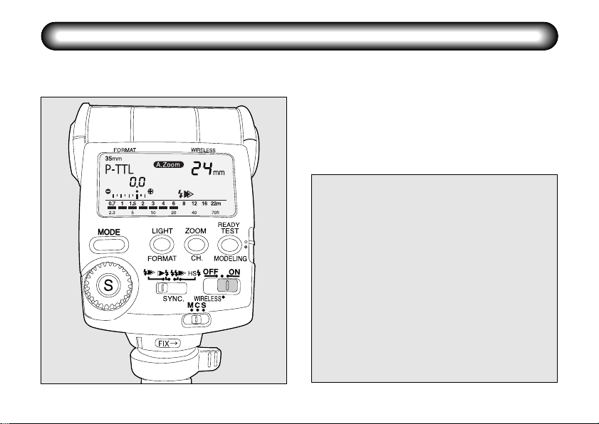
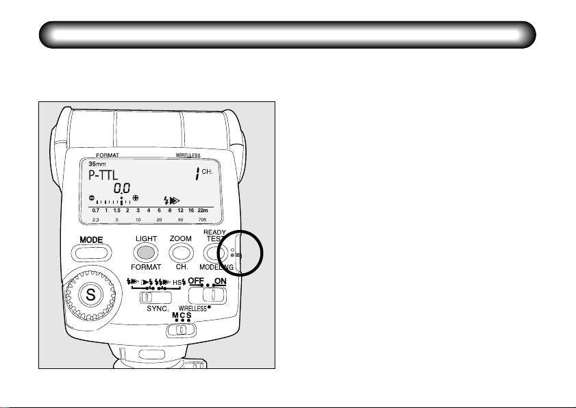
LCD panel illumination button/Format button
Flash zoom button/Channel button
Test button/Modeling flash button/Ready lamp
Setting switch
Power switch
Wireless mode switch
Sync mode switch
Adjustment dial
Select button
Flash mode button
LCD panel
Bounce angle adjustment

9

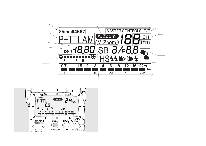
LCD Panel Indication
Zoom indicator
Format display : [35mm] → [645] → [67]
Flash mode display : [P-TTL] → [A] → [M] → [SB]
Flash exposure compensation indicator : [-3.0 ~ +1.0 stops, 0.5 stop increments]
ISO indicator : ISO 25 ~ 1600
Bar graph
Effective flash range indicator : [Closest distance] - [Maximum distance] (in P-TTL, TTL, A modes)
AF spot beam : [SB]
Synchronization mode indicator : [Leading-shutter-curtain sync: ] - [Trailing-shutter-curtain sync: ] -
Bounce flash warning : [ ]
Flash adjustment display : [
f/number display : F2 ~ F22
Channel indicator : Channels 1 ~ 4
Wireless mode indicator : [MASTER], [CONTROL], [SLAVE]
10
[A. Zoom] → [M. Zoom] xxmm = 20, 24, 28, 35, 50, 70, 85 [35mm format]
:
Optimum distance in manual mode
[Contrast-control-sync: ] -[High-speed-sync: ]
/
]
35, 45, 55, 70, 100, 135, 150 [645 format]
55, 60, 70, 90, 120, 180, 190 [67 format]
When in poorly lit locations and the display panel
cannot be seen, pressing this button will illuminate
the panel for about 10 seconds. Pressing it again
will turn off the illumination.
11

INSERTING THE BATTERIES
Slide the battery chamber cover as shown in
12
the figure to remove.
12
Insert four AA-size batteries, making sure the
plus/minus marking () match the diagram
inside the battery chamber cover.

When the power switch is set to the [ON]
3
position, the Ready Lamp lights up to indicate
that the flash has been charged and is ready to
fire. Then, by pressing the Test Button, the test
flash will fire.
BATTERIES
This flash unit operates with four AA-size batteries
as shown below.
Alkaline battery : LR6
Lithium battery : FR6
Nickel Hydroxide battery : Ni-MH
The flash unit charges in approximately 6 seconds
with brand new alkaline batteries, 5 seconds with
Nickel Hydroxide battery and 6 seconds with lithium
batteries. If charging time takes more than 20
seconds, then the batteries are weak and should be
replaced with the same type of new batteries.
•
If the batteries are not inserted properly, the Ready Lamp
will not light up. Insert the batteries correctly. If the flash
is not turned on when you insert the batteries correctly,
insert brand new alkaline batteries.
•
If you let the flash unit fire in succession on
lithium batteries, heated batteries would
activate the safety circuit so that the firing is
temporarily disabled. In this case, take time to
reduce the battery temperature and it would
bring you back to the normal condition of use.
13
NOTES ON THE POWER SUPPLY
Sliding the Power Switch to the ON position will turn ON the power, sliding it to the OFF position will turn OFF
the power.
• Please refer to page 34 for the WIRELESS
MODE position.
• When the power is turned OFF and ON again,
the flash mode will be set to P-TTL and the
Zoom position A.
Auto Power Off Function
When the flash unit is left unused for about 3
minutes with the power switch set to the [ON]
position, its power automatically switches off to
save on power. To restart charging of the flash
unit, turn ON the power. If the flash unit is
mounted on the cameras, press the shutter
release button lightly to turn ON the power.
•
The power will shut off after approximately 6
minutes only when set to auto flash mode
[A].
• During wireless flash operation, the power
will turn off after about 1 hour of non
operation.
14
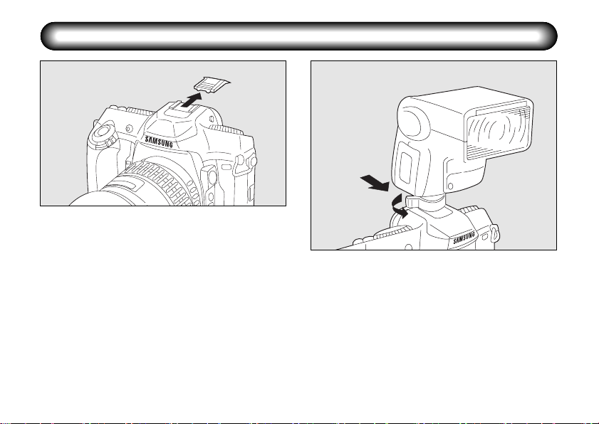
MOUNTING TO CAMERA
12
Remove the hot shoe cover from the camera.
1
Slide the shoe bracket into the camera's hot
2
shoe and then turn the locking lever in the
direction of the arrow to secure it in place. To
remove it, loosen the locking lever and slide it
off the camera.
• When the flash unit is attached to the GX and
the locking lever is turned toward [FIX
lock it, the locking pin will be extended for
secure locking.
→ ] to
• Turn the locking lever in the opposite direction
indicated by [FIX → ] before sliding the shoe
bracket into the camera's hot shoe.
15

SEF-36PZF FLASH MODES
The SEF-36PZF has the following flash modes. Select the mode best suited for the subject.
P-TTL auto flash
1
P-TTL auto flash [P-TTL] Works with the GX
camera.
A pre-flash is fired before the main flash fires so
that the multi-segment metering sensor can
measure the subject's distance, brightness,
backlit condition, etc. The data obtained is
incorporated to set the output of the main flash.
This mode obtains more accurate results than
with the conventional TTL mode.
Auto flash
2
The built-in flash metering sensor adjusts the
flash output automatically.
Use with cameras that are not P-TTL Auto flash
compatible.
16
Manual flash [M]
3
Use the flash unit's Guide No. to calculate the
correct flash range and aperture. This mode
works with the all cameras
AF spot beam
4
Under low-light or low-contrast conditions, a red
AF-assist beam is emitted to enable
autofocusing.
PICTURE FORMATS AND FLASH COVERAGE
The SEF-36PZF's flash coverage can be adjusted with the auto or manual zoom head to suit the camera's
picture format and lens focal length. Follow the procedure below.
Camera Format Size: [FORMAT] setting
1
❶
Slide the setting switch down [yellow dot].
❷ Press the [FORMAT] button and set to the
camera format size(35mm → 645 → 67)
being used.
❸ Slide the setting switch back up [white dot]
when complete.
❷
❶
• When used with GX camera, the format size
will automatically be set when the shutter
release button is pressed halfway down.
• The zoom indicator displayed when the
camera and flash transmit data may differ from
the zoom indicator displayed when the
exposure meter of camera is turned off.
《17》
 Loading...