

Samsung SDS-P4082, SDS-P5082, SDS-P5102, SDS-P4042, SDS-P3042 User Manual
...
4/8/16 CHANNEL DVR
User Manual
SDS-P3042/P4042/P4082/P5082/P5102/P5122

4/8/16 Channel DVR
User Manual
Copyright
©2013 Samsung Techwin Co., Ltd. All rights reser ved.
Trademark
The name of this product is the registered trademark of Samsung Techwin Co., Ltd.
Other trademarks mentioned in this manual are the registered trademark of their respective company.
Restriction
Samsung Techwin Co., Ltd shall reserve the copyright of this document. Under no circumstances, this document shall be reproduced,
distributed or changed, partially or wholly, without formal authorization of Samsung Techwin.
Disclaimer
Samsung Techwin makes the best to verif y the integrity and correctness of the contents in this document, but no formal guarantee shall be
provided. Use of this document and the subsequent results shall be entirely on the user's own responsibility. Samsung Techwin reserves the
right to change the contents of this document without prior notice.
Design and specifications are subject to change without prior notice.
The initial administrator ID is “admin” and the password should be set when logging in for the first t ime.
Set password for your wireless network if you use the product with a wireless router. Being not protected with pa ssword or
using the default wireles s router password may expose your video dat a to potential threat.
Please change your password ever y three months to safely protect personal information and to prevent the damage of t he
information theft.
Please, take note that it’s a user’s responsibility for the securit y and any other problems caused by mismanaging a password.
is the registered logo of Samsung Techwin Co., Ltd.
overview
IMPORTANT SAFETY INSTRUCTIONS
Read these operating instructions carefully before using the unit.
Follow all the safety instructions listed below.
Keep these operating instructions handy for future reference.
1) Read these instructions.
2) Keep these instructions.
3) Heed all warnings.
4) Follow all instructions.
5) Do not use this apparatus near water.
6) Clean only with dry cloth.
7) Do not block any ventilation openings, Install in accordance with the manufacturer’s instructions.
8) Do not install near any heat sources such as radiators, heat registers, stoves, or other apparatus
(including amplifiers) that produce heat.
9) Do not defeat the safety purpose of the polarized or grounding- type plug. A polarized plug has two
blades with one wider than the other. A grounding type plug has two blades and a third grounding
prong. The wide blade or the third prong are provided for your safety. If the provided plug does not fit
into your outlet, consult an electrician for replacement of the obsolete outlet.
10) Protect the power cord from being walked on or pinched particularly at plugs, convenience
receptacles, and the point where they exit from the apparatus.
11) Only use attachments/accessories specified by the manufacturer.
12) Use only with the cart, stand, tripod, bracket, or table specified by the
manufacturer, or sold with the apparatus. When a cart is used, use caution
when moving the cart/apparatus combination to avoid injury from tip-over.
13) Unplug this apparatus during lightning storms or when unused for long periods
of time.
14) Refer all servicing to qualified service personnel. Servicing is required when the
apparatus has been damaged in any way, such as power-supply cord or plug is
damaged, liquid has been spilled or objects have fallen into the apparatus, the apparatus has been
exposed to rain or moisture, does not operate normally, or has been dropped.
! overview
English _3
overview
CAUTION
RISK OF ELECTRIC SHOCK.
DO NOT OPEN
CAUTION
: TO REDUCE THE RISK OF ELECTRIC SHOCK, DO NOT REMOVE COVER (OR BACK) NO USER
SERVICEABLE PARTS INSIDE. REFER SERVICING TO QUALIFIED SERVICE PERSONNEL.
This symbol indicates that dangerous voltage consisting a risk of electric shock is present within
this unit.
This exclamation point symbol is intended to alert the user to the presence of important operating
and maintenance (servicing) instructions in the literature accompanying the appliance.
WARNING
•
To reduce the risk of fire or electric shock, do not expose this appliance to rain or moisture.
•
To prevent injury, this apparatus must be securely attached to the floor/wall in accordance with the installation
instructions.
WARNING
1. Be sure to use only the standard adapter that is specified in the specification sheet.
Using any other adapter could cause fire, electrical shock, or damage to the product.
2. Incorrectly connecting the power supply or replacing battery may cause explosion, fire, electric shock, or
damage to the product.
3. Securely plug the power cord into the power receptacle. Insecure connection may cause fire.
4. When installing the camera, fasten it securely and firmly. The fall of camera may cause personal injury.
5. Do not place conductive objects (e.g. screwdrivers, coins, metal parts, etc.) or containers filled with water on
top of the camera. Doing so may cause personal injury due to fire, electric shock, or falling objects.
6. Do not install the unit in humid, dusty, or sooty locations. Doing so may cause fire or electric shock.
7. If any unusual smells or smoke come from the unit, stop using the product. In such case, immediately
disconnect the power source and contact the service center. Continued use in such a condition may cause fire
or electric shock.
8. If this product fails to operate normally, contact the nearest service center. Never disassemble or modify this
product in any way. (SAMSUNG is not liable for problems caused by unauthorized modifications or attempted
repair.)
9. When cleaning, do not spray water directly onto parts of the product. Doing so may cause fire or electric shock.
10. Do not expose the product to the direct airflow from an air conditioner.
Otherwise, it may cause moisture condensation inside the Clear Dome due to temperature difference between
internal and external of the dome camera.
11. If you install this product in a low-temp area such as inside a cold store, you must seal up the wiring pipe with
silicon, so that the external air can not flow inside the housing.
Otherwise, external high, humid air may flow inside the housing, pooling moisture or vapor inside the product
due to a difference between internal and external temperature.
4_ overview
BEFORE START
This user manual provides Information for using the DVR such as brief introduction, part names, functions, connection
to other equipment, menu setup, etc.
You have to keep in mind the following notices :
• SAMSUNG retains the copyright on this manual.
• This manual cannot be copied without SAMSUNG’s prior written approval.
• We are not liable for any or all losses to the product incurred by your use of non-standard product or violation
of instructions mentioned in this manual.
• Prior to opening the case, please consult a qualified technician first. Whenever this is needed power must be
removed from the unit.
• Before installing an additional HDD or connecting an external storage device (USB HDD) to this DVR, check the
compatibility. Consult your provider for the compatibility list.
Warning
❖ Battery
It is essential that when changing the battery in the unit, the replacement battery must be of the same type
otherwise there may be a possibility of an explosion.
The following are the specifications of the battery you are using now.
• Normal voltage : 3V
• Normal capacity : 170mAh
• Continuous standard load : 0.2mA
• Operating temperature : -20°C ~ +85°C
Caution
• Connect the power cord into a grounded outlet.
• The Mains plug is used as a disconnect device and shall stay readily operable at any time.
• Batteries shall not be exposed to excessive heat such as sunshine, fire or the like
• Risk of Explosion if Battery is replaced by an Incorrect Type. Dispose of Used Batteries According to the
Instructions.
(-4°F ~ +185°F)
CALIFORNIA USA ONLY
This Perchlorate warning applies only to primary CR (Manganese Dioxide)
Lithium coin cells in the product sold or distributed ONLY in California USA.
“Perchlorate Material - special handling may apply, See www.dtsc.ca.gov/
hazardouswaste/perchlorate.”
! overview
❖ System Shutdown
Turning off the power while the product is in operation, or undertaking improper actions may cause damage
or malfunction to the hard drive or the product.
Please turn off the power, please right-click to display the context sensitive menu and select <Shutdown>.
After selecting <OK> in the pop-up menu, you can pull off the power cord.
You may want to install a UPS system for safe operation in order to prevent damage caused by an
unexpected power stoppage. (Any questions concerning UPS, consult your UPS retailer.)
❖ Operating Temperature
The guaranteed operating temperature range of this product is 0°C ~ 40°C (32°F ~ 104°F).
This product may not work properly if you run right after a long period of storage at a temperature below the
guaranteed one.
Prior to using a device that has been stored for a long period in low temperatures, allow the product to stand
at room temperature for a period.
Especially for the built-in HDD in the product, its guaranteed temperature range is 5°C ~ 55°C (41°F ~ 131°F).
Likewise, the hard drive may not work at a temperature below the guaranteed one.
❖ Ethernet Port
DVR is designed for indoor use only and all the communication wirings are limited to inside of the building.
English _5

over
view
ConTenTS
overvIeW
3
ConneCTInG WITh oTher devICe
14
LIve
20
3 Important Safety Instructions
5 Befor
Contents
6
Featur
8
Part Names and Functions (Fr
10
Part Names and Functions (Rear)
11
12 Remote Contr
14 installation
14 Checking the Installation Envir
15
Connecting External Devices
15 Connecting the USB
Connecting Exter
15
16
Connecting the Camera (SDC-7340BC)
18 Connecting the RS-485 Device
18 Connecting the Network
20 Getting Started
22 Live Screen Configuration
27 Live Mode
30 Zoom
30 Audio On/Off
30 Freeze
31 Event Monitoring
e Start
es
ont)
ol
onment
nal SATA HDD
6_ overview
mAIn menu
32
32 System Setup
44 Setting the Device
53 Setting the Recor
56
Setting the Event
58 Backup
60 Network Configuration
73 Contr
olling a PTZ Device
ding

SEARCH & PLAY
76
76 Search
79 Playback
! overview
WEB VIEWER
81
BACKUP VIEWER
111
APPENDIX
113
81 Introducing Web Viewer
82 Connecting Web Viewer (Windows)
84 Using Live Viewer (Windows)
92 Using Search Viewer
95 Viewer Setup
106 About
107 Connecting Web Viewer (Mac)
108 Using Live Viewer (Mac)
110 Mobile Viewer
111 SEC Backup Viewer
113 Product Specification (Camera)
114 Product Specification(DVR)
120 Product Overview
123 Default Setting
126 Troubleshooting
129 Open Source License Report on the Product
English _7

overview
FEATURES
The DVR employs H.264 video encoding for 4, 8 or 16 channel inputs and G.711 audio encoding for 4, 8 or 16
channels while simultaneously supports hard disc recording and playback.
These DVRs also supports network connectivity, providing remote monitoring from a remote PC transferring video
and audio data.
•
Provides a convenient User Interface
•
4/8/16 CH Composite Input Connectors
•
Supports WD1/CIF/2CIF/4CIF recording formats
•
With the network specific codec, network transfer enabled regardless of the recording conditions
•
De-interlacing processor for better picture quality
•
Display of HDD information and status by using HDD SMART
•
Hard Disk overwrite function
•
Mass storage hard disk backup through high-speed USB 2.0
•
Simultaneous Record and Playback of 4/8/16-channel video data
•
Various Search Modes (Search by Time, Event, Backup and Motion Detection)
•
Various Recording Modes (Manual, Event, Scheduled Recording)
•
Alarm Interface
•
Remote Monitoring function by Network Viewer, Smart Viewer and Mobile Viewer
Standards Approvals
This equipment has been tested and found to comply with the limits for a Class A digital device, pursuant to part 15 of the
`
M
FCC Rules. These limits are designed to provide reasonable protection against harmful interference when the equipment is
operated in a commercial environment.
This equipment generates, uses, and can radiate radio frequency energy and, if not installed and used in accordance with
the instruction manual, may cause harmful interference to radio communications. Operation of this equipment in a
residential area is likely to cause harmful interference in which case the user will be required to correct the interference at
his own expense.
8_ overview
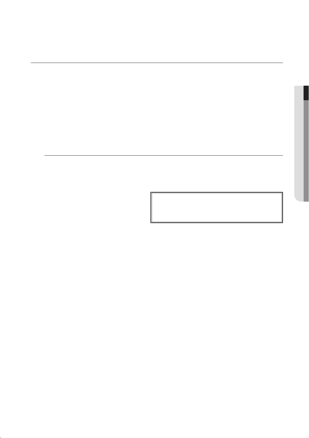
Package Contents
Please unwrap the pr
oduct, and place the product on a flat place or in the place to be installed.
Please check the following contents are included in addition to the main unit.
POWER REC NETWORK
DVR (1SET) Ada
Remote Control (1EA) / Ba
Camera Power Cable*
(5 splitter or 9 splitter)
ttery (2EA) SDC-7340BC * Camera Cable * (
pter * / Power Cable * Mouse (1EA)
Network Cable (1EA) HDMI Cable(1EA)
60FT or 90FT
! OVER
VIEW
)
Expansion pipe and Screw * Manual CD (1EA) Quick Start Guide (1EA)
W
arranty Card (1EA)
M
odel SDC-7340BC Adapter/Power cable Camera Cable
SDS-P3042 4EA 1EA 60FT: 4EA 12EA/12EA 5 splitter 1EA
SDS-P4042 4EA 1EA 60FT: 4EA 12EA/12EA 9 splitter 1EA
SDS-P4082 8EA 1EA 60FT: 6EA, 90FT: 2EA 24EA /24EA 9 splitter 1EA
SDS-P5082 8EA 2EA 60FT: 6EA, 90FT: 2EA 24EA /24EA 5 splitter 1EA
SDS-P5102 10E A 2EA 60FT: 8EA, 90FT: 2EA 30EA/30EA 5 splitter 1EA
SDS-P5122 12E A 2EA 60FT: 9EA, 90FT: 3EA 36EA/36EA 5 splitter 1EA
Expansion pipe and Screw
Camera Power ca
9 splitter 1EA
9 splitter 1EA
9 splitter 1EA
English _9
ble
overview
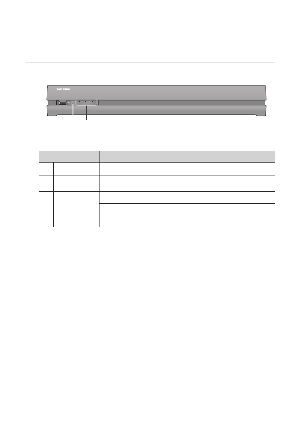
PART NAMES AND FUNCTIONS (FRONT)
POWER REC NETWORK
a
Part Names Functions
USB Port Connects the USB devices.
a
Remote Control
b
Receiver
LED Indicator
c
All functions are operable with mouse control, since there are no front buttons.
`
M
b
c
Input the remote control signal.
POWER : Displays the power ON/OFF status.
REC : Lights on when recording is in progress.
NETWORK : Displays both network connection and data transfer status.
10_ overview
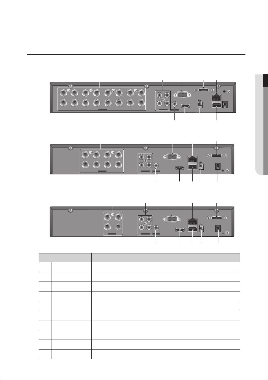
PART NAMES AND FUNCTIONS (REAR)
VGA
LAN
RS485
IN1
CH1 CH2
CH3 CH4
IN2
IN3 IN4
AUDIO INVIDEO IN
HDMI DC 12 V
USB
eSATA
AUDIO OUT
VGA
LAN
RS485
IN1
CH1 CH2 CH3 CH4 CH5 CH6 CH7 CH8
CH9 CH10 CH11 CH12 CH13 CH14 CH15
IN2
IN3 IN4
AUDIO INVIDEO IN
HDMI DC 12 V
USB
eSATA
AUDIO OUT
CH16
VGA
LAN
RS485
IN1
CH1 CH2
CH3 CH4
IN2
IN3 IN4
AUDIO INVIDEO IN
HDMI DC 12 V
USB
eSATA
AUDIO OUT
SDR-5102
a
CH1 CH2 CH3 CH4 CH5 CH6 CH7 CH8
CH9 CH10 CH11 CH12 CH13 CH14 CH15
CH16
b
IN1
IN3 IN4
AUDIO INVIDEO IN
c
IN2
VGA
HDMI DC 12 V
AUDIO OUT
d e
eSATA
RS485
LAN
USB
! overview
SDR-4102
a b
CH1 CH2 CH3 CH4
CH5 CH6 CH7 CH8
SDR-3102
a
CH1 CH2
CH3 CH4
Part Names Functions
VIDEO IN Input port for the composite video signal.
a
AUDIO IN Input ports (RCA jack) for the audio signal.
b
IN1
IN2
IN3 IN4
AUDIO INVIDEO IN
AUDIO OUT
b
IN1
IN2
IN3 IN4
AUDIO INVIDEO IN
AUDIO OUT
j
c
VGA
c
VGA
e d
LAN
HDMI DC 12 V
USB
e d
LAN
HDMI DC 12 V
USB
fghij
eSATA
RS485
hgij
hgi
f
eSATA
RS485
f
VGA OUT Output port for VGA video signal.
c
e-SATA Ports used for external storage device connections.
d
NETWORK NETWORK connector port.
e
DC 12V DVR power input port.
f
USB USB connector port.
g
RS-485 Used to establish RS-485 communications.
h
HDMI HDMI connector port.
i
AUDIO OUT Output port (RCA jack) for the audio signal.
j
English _11
overview
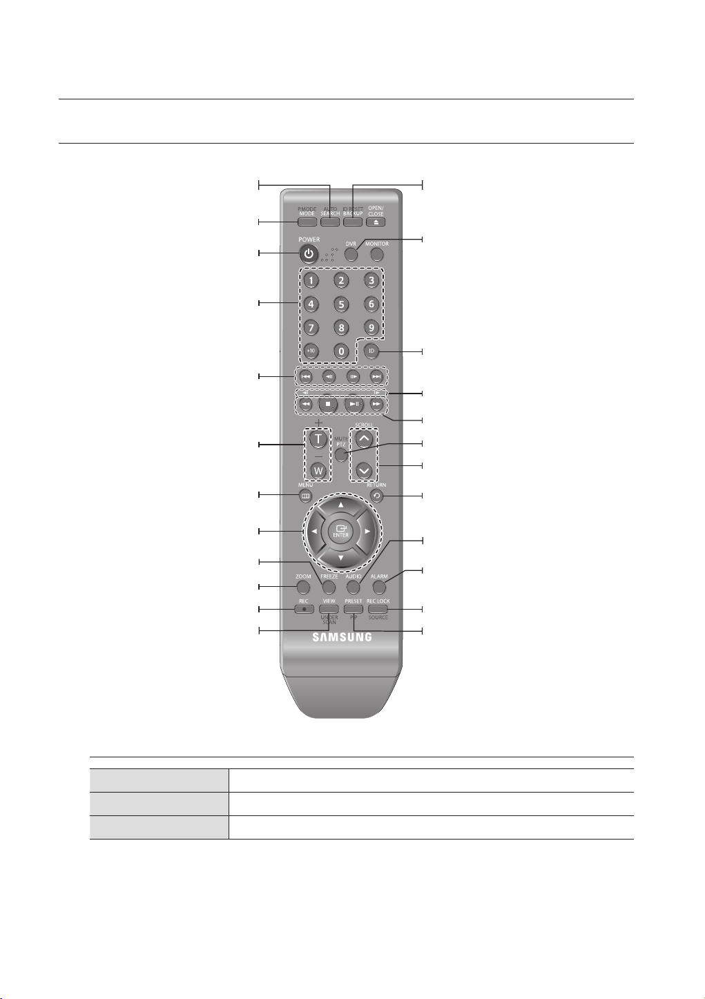
REMOTE CONTROL
Displays the search menu.
Changes the screen mode.
Displays the Exit pop up screen.
Used as the numeric input keys, or displays a single
Skip Backward (by unit time),
Slow Rewind, Slow Forward,
Skip Forward (by unit time)
Goes to the system menu screen.
Up/Down/Left/Right(
Moves the cursor up/down/left/right, and runs the
Freezes the screen temporarily.
Runs the digital zoom (x2) function.
Starts or ends the live recording.
Runs the View function in the PTZ mode.
SEARCH
MODE
POWER
NUMBER [0~+10]
channel.
T/W
Zooms in or out.
MENU
$%_ +
)/ENTER
Select Menu.
FREEZE
ZOOM
REC
VIEW
BACKUP
Displays the Backup Menu.
DVR
Activates the DVR function.
ID
Sets the ID of the system.
Select 2 digits from 0 ~ 9 while pressing the ID Key.
Move Frame
While paused, moves to the previous/next frame.
FR, STOP, PLAY/PAUSE, FF
PTZ
Displays or ends PTZ.
,.
SCROLL
Moves the menu scroll.
RETURN
Returns to the previous screen.
AUDIO
Turns Audio on/off.
ALARM
Cancels the Alarm.
REC LOCK
Selects the recording lock function.
PRESET
Displays the Preset Setup.
Using the numeric buttons
CHANNEL 1–9 Press each button between 1 to 9. (8CH : 8)
CHANNEL 10 Press the [0/+10] button first, then press the [0/+10] within 1 second.
CHANNEL 11–16 Press the [0/+10] button first, then press any number between 1 to 6.
12_ overview

Changing the Remote Control ID
1. Press the [ID] button of the remote control and check the ID displayed on the DVR screen.
The factory default ID of the remote control is 00.
2. Enter 2 digits of your selection in order, while pressing the system [ID] button.
3. When ID input is done, press the system [ID] button again to check the setting.
If you want to change the remote control ID to 08: Press 0 and 8 in order while the system [ID] button is pressed.
`
M
Remote control's ID and DVR’s ID should be matched for proper operation. Refer to “Remote Devices”. (Page 50)
! overview
English _13
connecting with other device
INSTALLATION
Please take note of the followings before using this product.
•
Do not use the product outdoor.
•
Do not spill water or liquid in the connection part of the product.
•
Do not impose the system to excessive shock or force.
•
Do not pull out the power plug forcefully.
•
Do not disassemble the product on your own.
•
Do not exceed the rated input/output range.
•
Use a certified power cord only.
•
For the product with an input ground, use a grounded power plug.
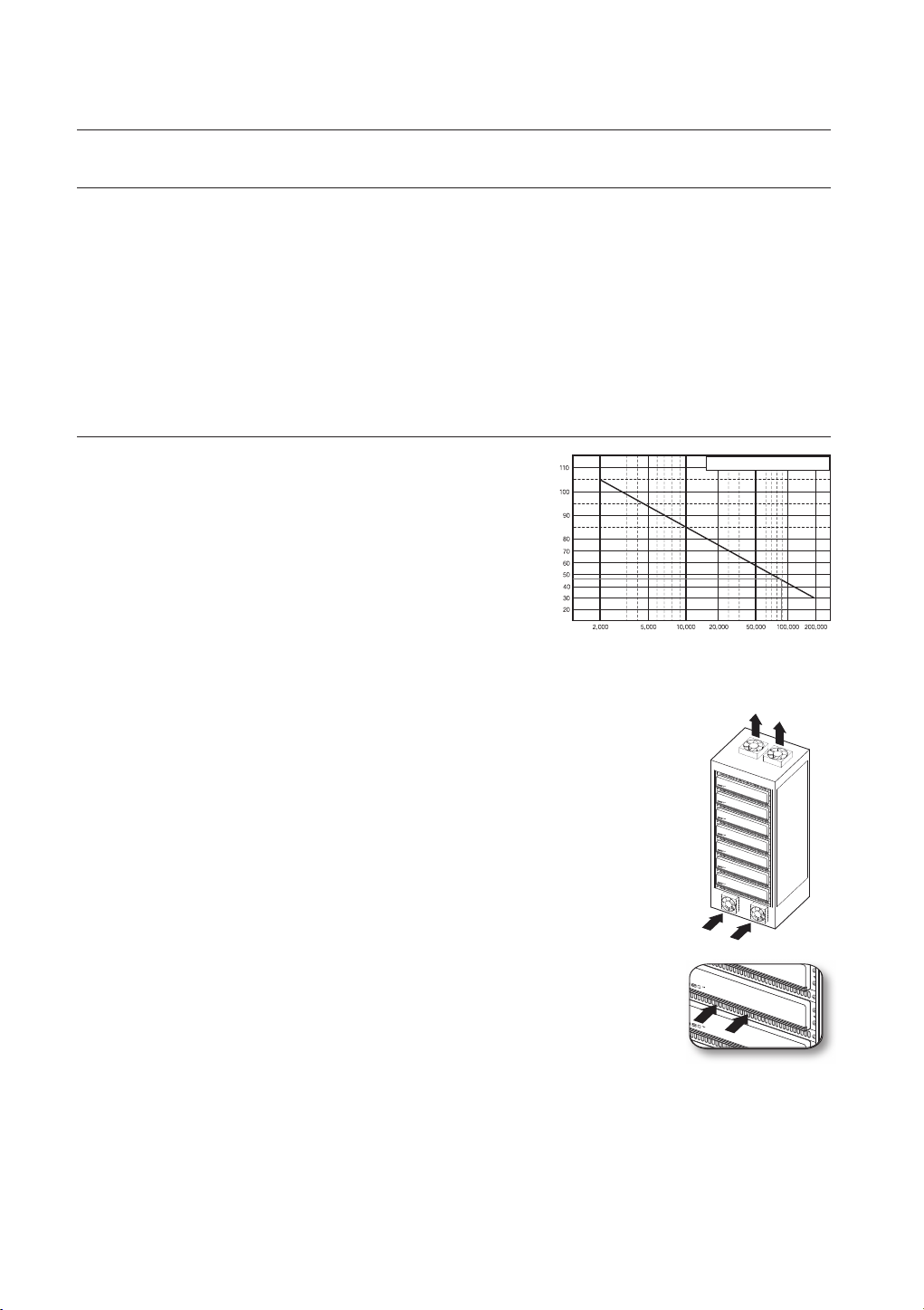
CHECKING THE INSTALLATION ENVIRONMENT
Samsung Digital Video Recorder (“DVR” hereinafter) is a stateof-art security device, and contains mass storage hard disk(s)
and critical circuits inside.
When the temperature rises inside the product, the product may
breakdown and the product life be shortened. Please pay
attention to the following recommendations before installation.
The followings are the recommendations when Samsung DVR is installed on a rack.
1. Please ensure that the rack inside is not sealed.
2. Please ensure the air is circulated through the inlet/outlet as shown in the picture.
3. If the DVR or other devices on a rack is to be stacked as in the picture, provide a
suitable space or install a ventilating opening for air circulation.
4. For natural air convection, place the inlet at the bottom of the rack and the outlet on top.
5. It is strongly recommended that a fan motor is installed at the inlet and the outlet for air
circulation. (Please fit a filter at the inlet to screen dust or foreign substances.)
6. Please maintain the temperature inside the rack or surrounding areas between
0°C ~ 40°C (32°F ~ 104°F) as shown in the figure 1.
Rack Mount Instructions - The following or similar rack-mount instructions are
included with the installation instructions :
A) Elevated Operating Ambient - If installed in a closed or multi-unit rack assembly, the
operating ambient temperature of the rack environment may be greater than room
ambient. Therefore, consideration should be given to installing the equipment in an
environment compatible with the maximum ambient temperature specified by the
manufacturer.
B) Reduced Air Flow - Installation of the equipment in a rack should be such that the
amount of air flow required for safe operation of the equipment is not compromised.
C) Mechanical Loading - Mounting of the equipment in the rack should be such that a
hazardous condition is not achieved due to uneven mechanical loading.
D) Circuit Overloading - Consideration should be given to the connection of the equipment to the supply
circuit and the effect that overloading of the circuits might have on overcurrent protection and supply wiring.
Appropriate consideration of equipment nameplate ratings should be used when addressing this concern.
E) Reliable Earthing - Reliable earthing of rack-mounted equipment should be maintained. Particular attention should
be given to supply connections other than direct connections to the branch circuit (e.g. use of power strips).
Temperature
Unit: ºC
One Year: 24HR X 365 DAY =8,760 HR
Life (Unit: HOURS)
[Figure 1]
[Figure 2]
14_ connecting with other device
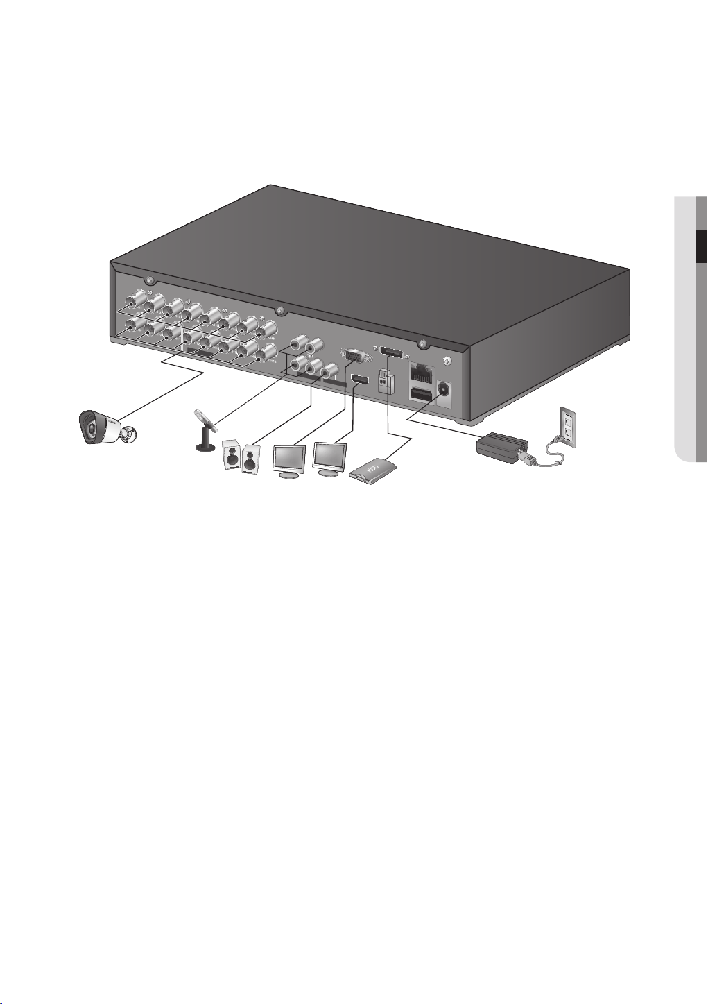
CONNECTING EXTERNAL DEVICES
CONSOLE
AUDIO IN
CH1
CH2
VGA OUT
DC 12V
NETWORK
AUDIO IN
VIDEO IN
VIDEO IN
1
2
3
4
5
6
7
8
9
10
11
12
13
14
15
16
CH3
CH4
AUDIO OUT
+ -
RS 485
! CONNECTING WITH OTHER DEVICE
VIDEO IN
IN1
IN3
AUDIO IN
IN4
IN2
AUDIO OUT
eSATA
RS485
LAN
USB
DC 12 V
VGA
HDMI
CONNECTING THE USB
1. By factory default, a USB port is provided for external connection.
2. You can connect a USB HDD, USB memory or mouse to the USB port.
3. If a USB HDD is connected to the system, recognition and settings are available in “Main Menu > Setting the
Device > Storage Device”. (Page 47)
4. This product supports hot-plugging, which connects/removes the USB device during the system operation.
If you use the USB device for Backup purposes, format it with FAT32 on PC if it is not formatted on the DVR.
`
J
CONNECTING EXTERNAL SATA HDD (ESATA)
External SATA port is provided on the rear panel.
If connected to the system, the external SATA HDD (eSATA) can be recognized and configured in “Main Menu >
Device > Storage Device”.
Use a cable shorter than 1 m for the external external SATA HDD (eSATA) connections.
`
J
Unexpected disconnection to a device in use which is connected via eSATA may restart the system. Check whether the
`
device is in use before disconnecting it.
In the event of replacing an HDD of an external SATA HDD, please power off the external SATA HDD to change the HDD.
`
English _15
connecting with other device
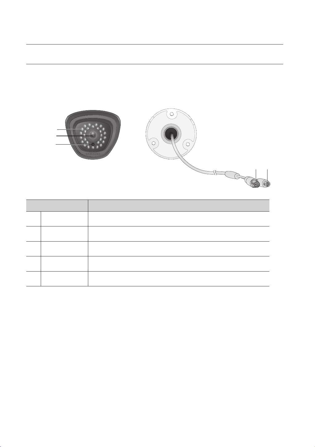
CONNECTING THE CAMERA (SDC-7340BC)
Equipped with the IR LED and the illumination sensor, enables you to monitor at night as well as in daytime.
The camera is suitable for both internal and external use.
Please make sure not to fully expose the camera to rain. The camera must be installed under a shelter to avoid exposure to excessive rain
`
or moisture.
a
b
c
e
d
Name Description
IR LED These infrared LED's are controlled by the illumination sensor.
a
Lens
b
Illumination Sensor Detects incoming light to control the IR LED.
c
BNC Cable BNC terminal for video signal output.
d
Power Cable Used to plug the power cable.
e
Focal length of 3.6mm enables you to cover relatively longer range of monitoring.
16_ connecting with other device
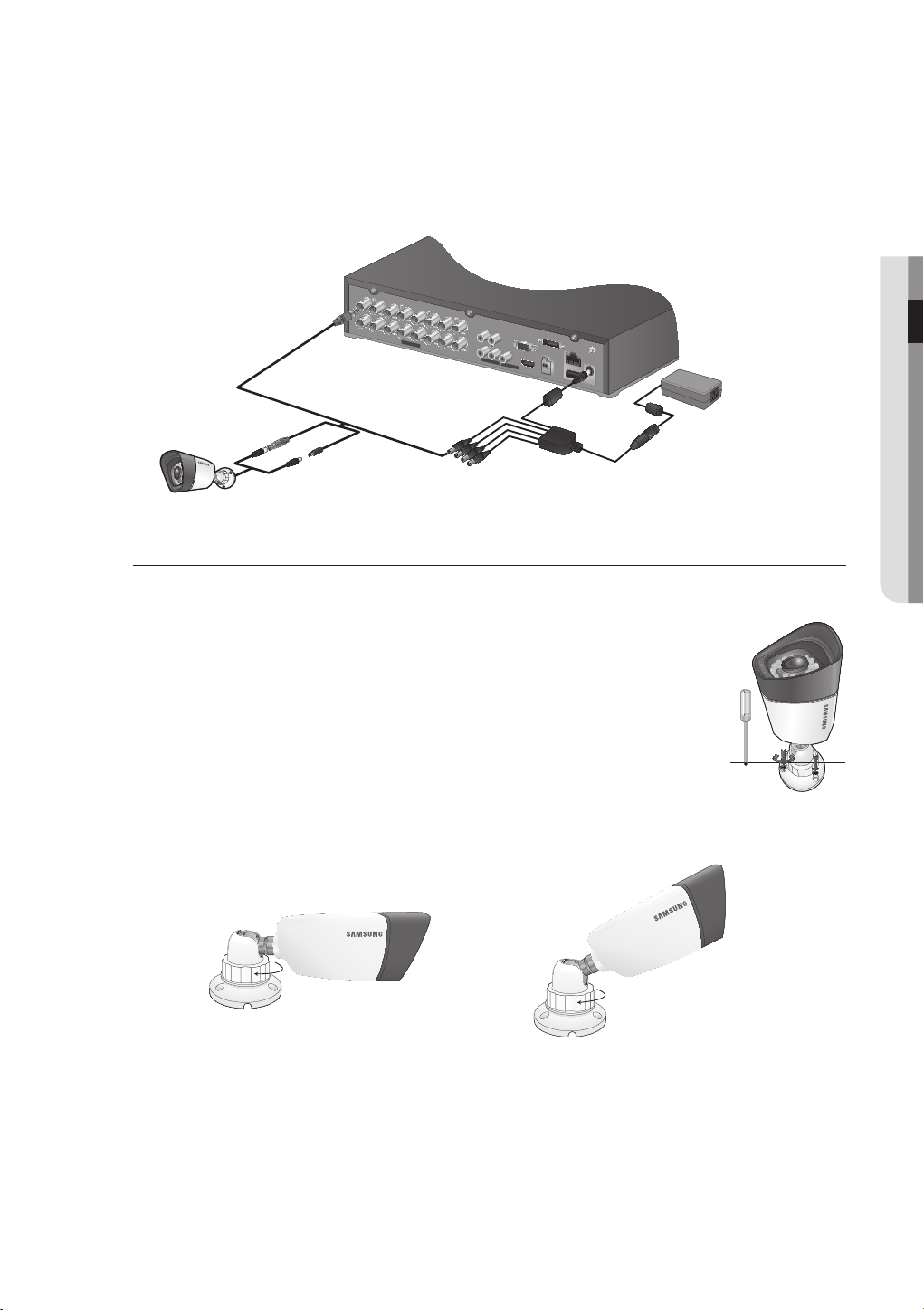
Connecting with DVR
SDC-7340BC : M4 X L20
bracket.
IN1
IN3
IN4
AUDIO IN
AUDIO OUT
VGA
LAN
RS485
IN2
HDMI
DC 12 V
USB
eSATA
VIDEO IN
The following figures are based on Model SDR-5102.
`
Installing the camera
The camera can be installed on the wall, ceiling, shelf or a desired position using the provided bracket.
1. Select a position where you want to install the camera.
Make sure the selected position can sustain the weight of the camera.
`
2. Attach the camera bracket to the wall using the supplied screws.
•
! CONNECTING WITH OTHER DEVICE
M4 X L20
sized screws
wall or ceiling
3. Adjust the camera to target the video location and tighten the camera bracket handle on the camera
Handle
Handle
4. Connect the camera cable to the camera.
You should be careful when installing the camera outdoors because the cable connectors may be wet with moisture or pile
`
J
up with impurities.
The camera satisfies the IP66 standard, and direct exposure to water or moisture may cause problem such as
`
condensation.
English _17
connecting with other device
IN1
IN3
IN4
AUDIO IN
AUDIO OUT
VGA
LAN
RS485
IN2
HDMI
DC 12 V
USB
eSATA
VIDEO IN
CONNECTING THE RS-485 DEVICE
Connect the rear [RS-485 +, –] port to the PTZ camera.
You can connect and control the PTZ camera which supports the RS-485 communication.
`
J
Check if the RS-485 device is compatible with the product first.
`
Pay attention not to change the polarity (+/-) of the RS-485 device when connecting it.
`
Depending on camera’s type, connection polarity can be different. For further information,
`
refer to the respective PTZ Camera’s documentation.
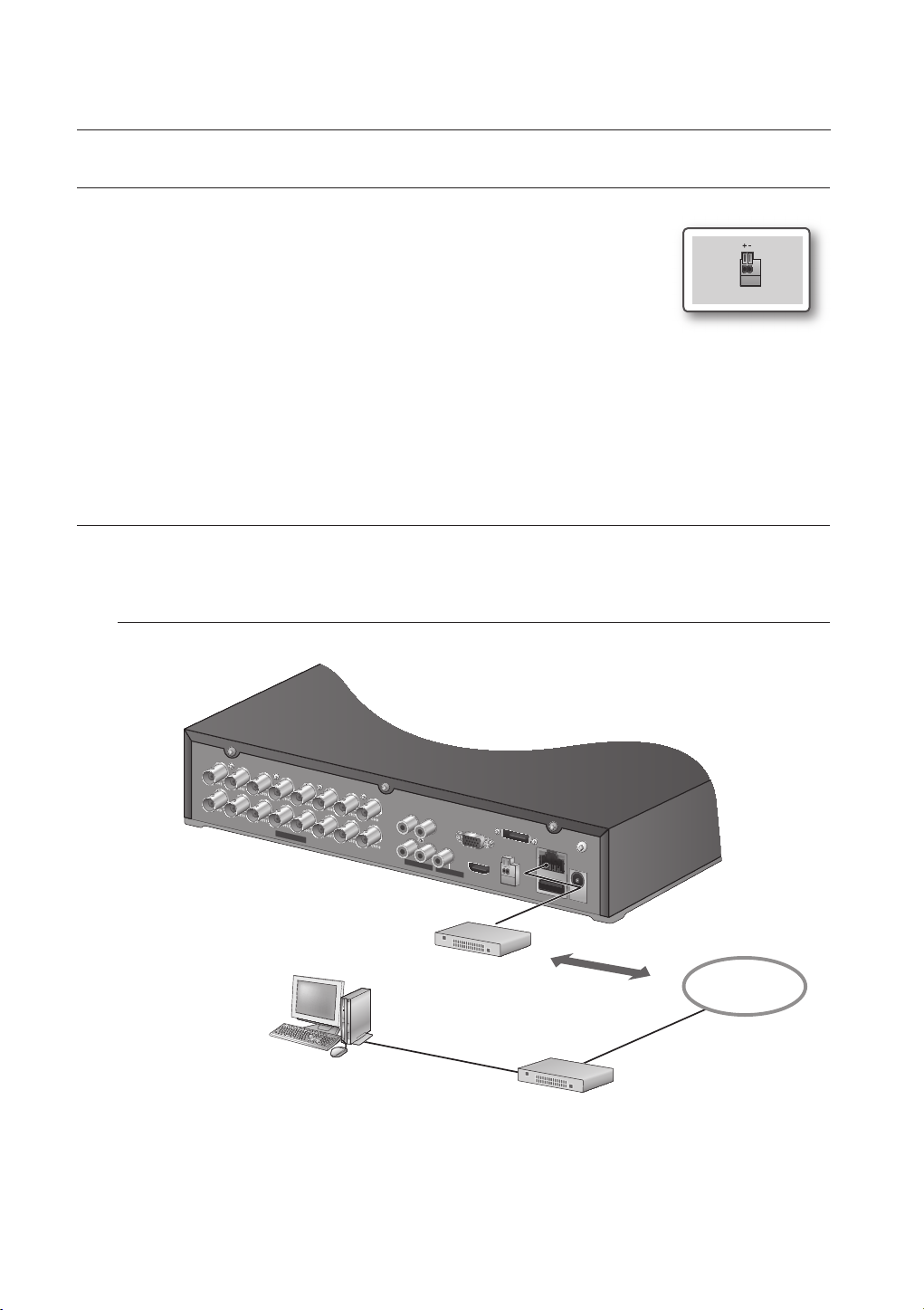
CONNECTING THE NETWORK
The following figures are based on Model SDR-5102.
`
Connecting to network through Ethernet (10/100BaseT)
RS485
18_ connecting with other device
Hub/Switcher
Windows
Network Viewer
RJ-45 Ethernet Cable
(Direct Cable)
Back Bone
NETWORK
Hub/Switcher
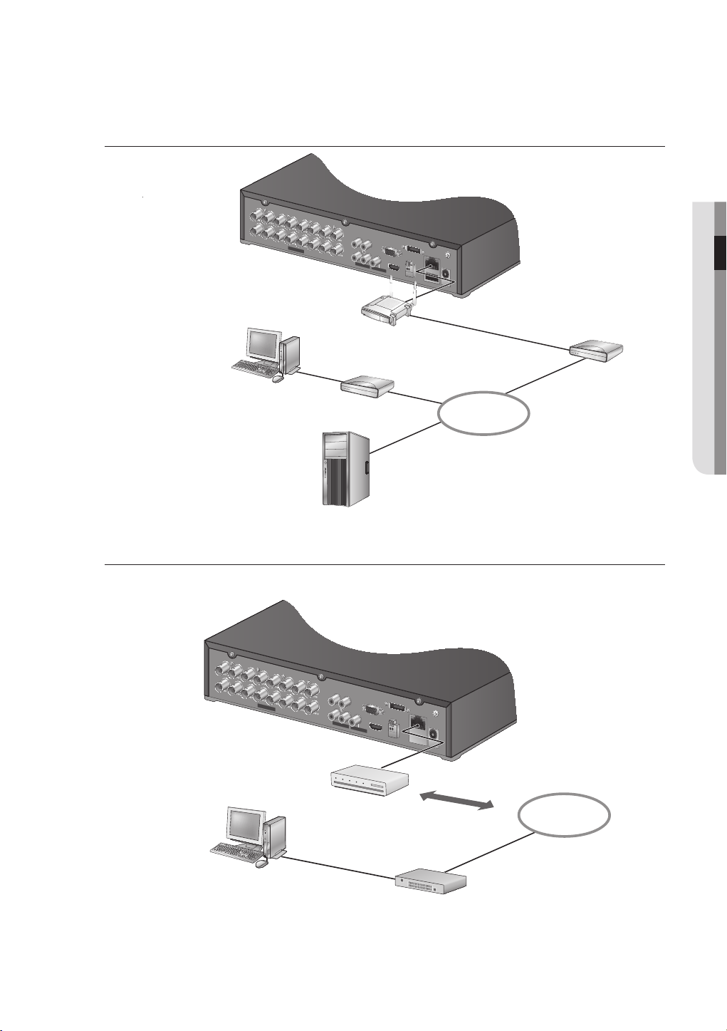
Connecting to the Network using the router
IN1
IN3
IN4
AUDIO IN
AUDIO OUT
VGA
LAN
RS485
IN2
HDMI
DC 12 V
USB
eSATA
VIDEO IN
IN1
IN3
IN4
AUDIO IN
AUDIO OUT
VGA
LAN
RS485
IN2
HDMI
DC 12 V
USB
eSATA
VIDEO IN
Broadband Router
External
Remote PC
xDSL or Cable Modem
DDNS Server
(Data Center)
NETWORK
xDSL or Cable Modem
! CONNECTING WITH OTHER DEVICE
Connecting to Network through ADSL
ADSL MODEM
Windows
Network Viewer
RJ-45 Ethernet Cable
(Direct Cable)
Phone(ADSL) Line
Hub/Switcher
NETWORK
English _19
live
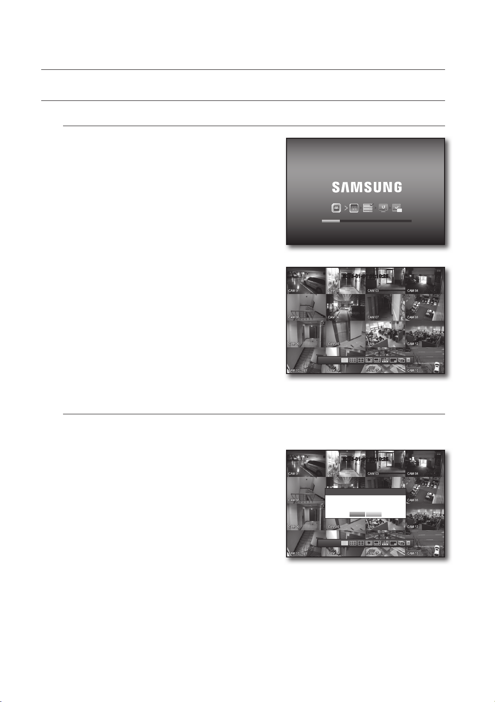
GETTING STARTED
Starting the system
1. Connect the power cable of the DVR to the wall outlet.
It takes about 10 seconds to display the start screen after
`
M
booting.
2. You will see the initialization screen.
The initialization process will last about 1 minute.
If a new HDD is installed, the initialization process may
take longer.
REC
3. The live screen appears with a beep.
2013-01-01
01:10:25
2013-01-01 01:10:25
Shutting Down the System
You can shut down the system only if you have logged in to the DVR.
You require permission to shut down the system if you are not logged in as admin.
1. Press the [POWER] button on the remote control, or
right-click to display the context sensitive menu and select
<Shutdown>.
2. The “Shutdown” confirmation window appears.
3. Use the arrow keys on the remote control to move to
<OK> and press the [ENTER] button or click <OK>. The
system will shut down.
For the permission management, refer to “Permission
`
M
Management > Setting Permissions”. (Page 39)
2013-01-01
01:10:25
Shutdown
2013-01-01 01:10:25
Are you sure to shutdown?
OK Cancel
20_ live
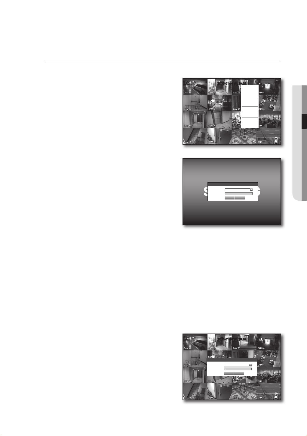
Login
To access a DVR or restricted menu, you should have logged in to the DVR.
1. In live mode, right-click any area of the screen.
You will see the context sensitive menu as in the right
figure.
2. Click <Login>.
The login dialog appears.
You can also see the login dialog to access a desired
menu by pressing the [MENU] button on the remote
control.
The login dialog will also appear if you press a menu button on
`
the remote control when the corresponding menu requires
logging in.
After logged in, press [RETURN] on the remote control to display
`
the logout dialog.
2013-01-01 01:10:25
Login
ID admin
Password
OK Cancel
Scene Mode
Audio Off
Freeze
Stop Alarm
Record
Play
Search
Backup
Main Menu
Shutdown
Hide Launcher
Login
! LIVE
The initial administrator ID is “admin” and the password should be set when logging in for the first time.
`
J
Set password for your wireless network if you use the product with a wireless router. Being not protected with password or
`
using the default wireless router password may expose your video data to potential threat.
Please change your password every three months to safely protect personal information and to prevent the damage of the
`
information theft.
Please, take note that it’s a user’s responsibility for the security and any other problems caused by mismanaging a
password.
For the restricted permission, refer to “Permission Management > Setting Permissions”. (Page 39)
`
M
Locking All Buttons
This will restrict access to all buttons available in the DVR.
1. In Live mode, press buttons on the remote control in the
order of [STOP (@)]
[MENU].
All buttons will be locked.
2. In the lock condition, press any button to display a dialog
where you are prompted to enter the password for
unlocking the buttons.
The button lock will be released if you enter the admin
password.
[FREEZE][STOP (@)][FREEZE]
2013-01-01 01:10:25
Key Lock Password
ID admin
Password
OK Cancel
English _21
live
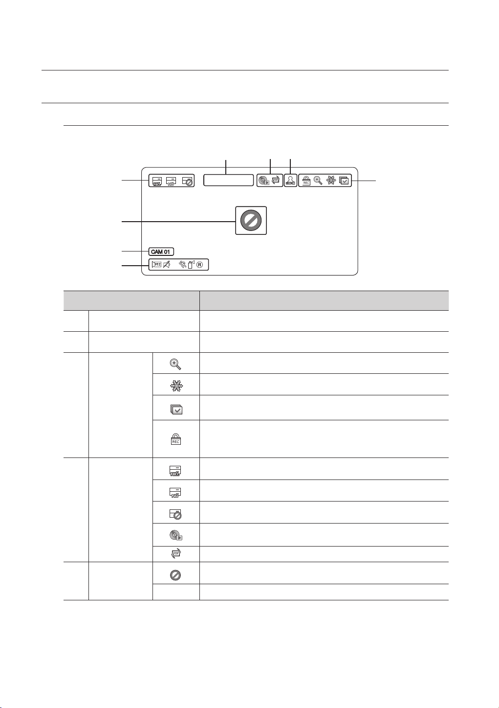
LIVE SCREEN CONFIGURATION
Icons on the Live Screen
You can check the status or operation of the DVR with the icons on the live screen.
a
b
c
bd
d
a
2013-01-01 00:00:01
e
f
CAM 01
g
Name Description
Current Date, Time Displays the current time and date.
Login Information When you are logged in, the “LOG ON” icon will be displayed.
Displayed if the zoom function is activated.
Freezes the screen temporarily.
Screen Mode
Displayed in Auto Sequence mode where all channels are switched at the specific
time interval.
This icon is displayed if a user with restricted access to the Record button tries to
make manual recording.
Only the user with the applicable permission can release (stop) the recording.
`
c
22_ live
System Operation
d
Video Input Status
e
Displayed if the HDD is full and the DVR has an insufficient space to record.
Displayed if no HDD is installed or the existing HDD should be replaced.
Displayed if the HDD needs a technical examination.
This will be displayed if the backup operation is in process.
Displayed if a new firmware is found from the network.
Displayed if no input is entered in the condition that the camera is set to <ON>.
Nothing will be displayed on the screen if the camera is set to <OFF>.
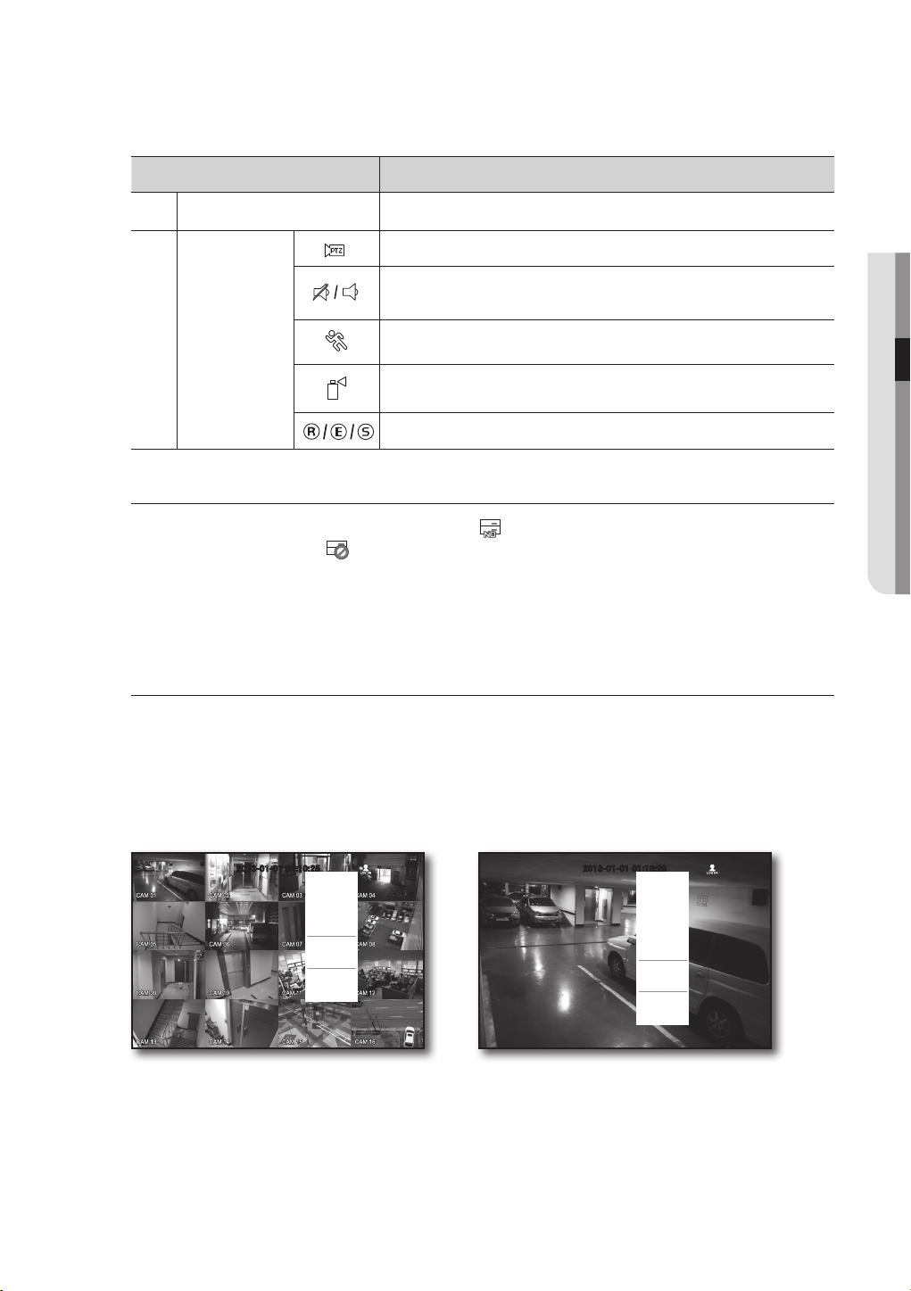
Name Description
f
Camera Name/ Channel Displays the camera name and the changed channel, if any.
Displayed in PTZ setting, and highlighted yellow if PTZ is in operation.
Displays AUDIO ON/MUTE.
Not displayed in video mode if deactivated.
Camera Operation
g
Displayed if a motion detected in the condition that the motion detection is set to
<ON>.
Appears when the Tampering Detection is set to <ON> and a tampering attempt is
detected.
Displays the current record mode from Record/Event/Schedule.
Error Information
• If the internal HDD is not connected, the “NO HDD”( ) message will appear; if there occurs a problem,
you will see the “HDD FAIL”(
) message in the top left corner. In this case, make sure you contact the
service center for assistance as this may cause a failure of recording, playback or backup.
If you see NO HDD, HDD FAIL icons on the screen, contact the service center for more details.
`
M
Live Screen Menu
In addition to the buttons on the remote control, you can access a desired menu by right-clicking the mouse
any area in live mode.
The context sensitive menu that appears by right-clicking the screen may differ, depending on the login/
logout, screen split mode and DVR operation mode.
! LIVE
Menu items of Search, Record, Backup and Shutdown can be deactivated, depending on the user permission.
`
M
2013-01-01 01:10:25
Scene Mode
Audio Off
Freeze
Stop Alarm
Record
Play
Search
Backup
Main Menu
Shutdown
Hide Launcher
Logout
< Split Mode Menu >
2013-01-01 01:10:25
Scene Mode
PTZ Control
Zoom In
Audio off
Freeze
Stop Alarm
Record
Play
Search
Backup
Main Menu
Shutdown
Hide Launcher
Logout
< Single Mode Menu >
English _23
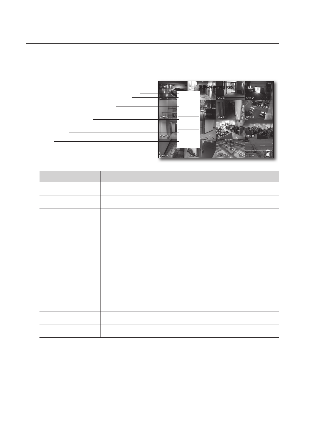
live
Split Mode Menu
The context sensitive menu in split mode differs, depending on the login/logout status.
a
b
c
j
k
l
Menu Description
Scene Mode Refer to “Live Mode”. (Page27)
Audio On/Off Refer to “Audio On/Off”. (Page 30)
Freeze Refer to “Freeze”. (Page 30)
i
h
g
f
e
d
c
b
a
Scene Mode
Audio Off
Freeze
Stop Alarm
Record
Play
Search
Backup
Main Menu
Shutdown
Hide Launcher
Logout
2013-01-01 01:10:25
Stop Alarm Stops the alarm output and the event monitoring. Refer to “Event Monitoring”.(Page 31)
d
Record/Stop Starts/stops the standard recording.
e
Play Plays the search result (data). Refer to “Search & Play > Play”. (Page 79)
f
Search Refer to “Search & Play > Search”. (Page 76)
g
Backup Refer to “Main Menu > Setting the Backup”. (Page 58)
h
Main Menu Accesses the main menu. Refer to the Using the DVR section. (Page 32)
i
Shutdown
j
Show/Hide Launcher
k
Login/Logout You can log in or out.
l
Turns down the DVR.
Shows or hides the launcher. Refer to “View the Launcher Menu”. (Page 26)
24_ live
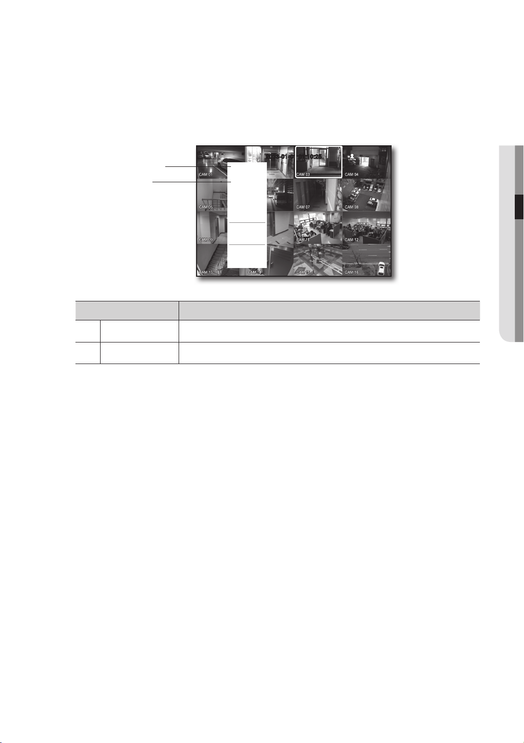
Single Mode Menu
The single mode menu is available only in Single Mode.
The context sensitive menu for the One Channel mode, in Split mode is different from that of the Single mode.
a
b
Full Screen
PTZ Control
Zoom In
Audio On
Freeze
Stop Alarm
Record
Play
Search
Backup
Main Menu
Shutdown
Hide Launcher
Logout
Menu Description
Full Screen
a
Zoom In Enlarges the selected image. (Page 30)
b
Select and click a desired channel in Split mode to switch to the full screen of the selected channel.
2013-01-01 01:10:25
! LIVE
Alarm Freeze
English _25
live
2013-01-01
01:10:25
2013-01-01
01:10:25
2013-01-01
01:10:25
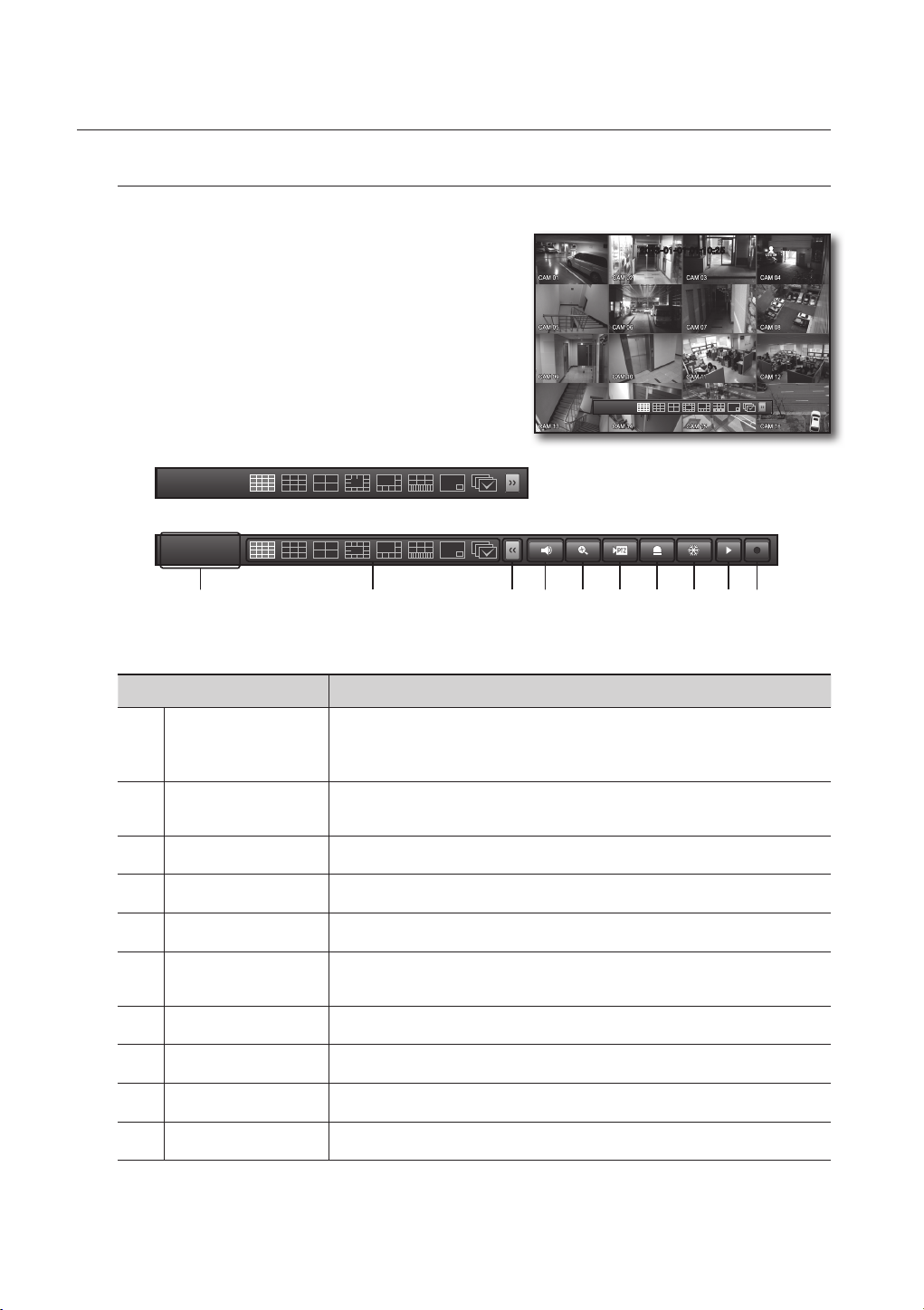
View the Launcher Menu
The Launcher menu appears on the bottom of the live screen.
1. In Live mode, right-click to display the context menu and
select <Show Launcher>.
2. Move the cursor to the bottom and click a desired item in
the Launcher menu.
If no input is entered for 10 seconds, the menu will disappear.
`
M
The Launcher menu can be accessed only by using the mouse.
`
SDR-4102, SDR-3102 does not support the 16-split screen
`
mode.
a c d e f g h ijb
2013-01-01
01:10:25
2013-01-01 01:10:25
Menu Description
Displays the current time and date.
Date/Time
a
Screen Mode
b
Menu Expansion Button Click to display the hidden menu to the right.
c
Audio Turns ON/OFF the sound of the selected channel.
d
Zoom Enlarges the selected area. This is available only in Single Live mode.
e
PTZ
f
Alarm Stops the alarm if it's activated.
g
Freeze Freezes the Live screen temporarily.
h
Play Enters Play mode if a file to play exist, and if not, enters Search mode.
i
Record Start/End recording the Live screen.
j
The indication of AM/PM is displayed if you set 12 hours for the time format in “System >
Date/Time/Language > Time”. (Page 32)
Press this button to switch the screen mode in sequence.
The current mode is highlighted in white.
Runs the PTZ Control launcher.
The PTZ control launcher will be active on the Live screen after you select a single channel.
26_ live
LIVE MODE
CH1 CH3
CH2
CH4 CH5 CH6
CH1 CH3
CH2
CH4 CH5 CH6
CH1 CH3
CH2
CH4 CH5 CH6
CH1CH7 CH8
CH1 CH3
CH2
CH4 CH5 CH6
CH1 CH3
CH2
CH4 CH5 CH6
CH1 CH3
CH2
CH4 CH5 CH6
CH1 CH3
CH2
CH4 CH5 CH6
CH1 CH3
CH2
CH4 CH5 CH6
CH1 CH3
CH2
CH4 CH5 CH6
CH1CH7 CH8
CH1 CH3
CH2
CH4 CH5 CH6
CH1 CH3
CH2
CH4 CH5 CH6
CH1 CH3
CH2
CH4 CH5 CH6
CH1 CH3
CH2
CH4 CH5 CH6
CH1 CH3
CH2
CH4 CH5 CH6
CH1 CH3
CH2
CH4 CH5 CH6
CH1CH7 CH8
CH1 CH3
CH2
CH4 CH5 CH6
CH1 CH3
CH2
CH4 CH5 CH6
CH1 CH2
CH3 CH4
CH1CH7 CH8
CH1 CH3
CH2
CH4 CH5 CH6
CH1
CH2
CH1 CH2
CH3 CH4
CH1CH7 CH8
CH1 CH3
CH2
CH4 CH5 CH6
CH1
CH2
CH1 CH2
CH3 CH4
CH1CH7 CH8
CH1 CH3
CH2
CH4 CH5 CH6
CH1
CH2
CH1 CH2
CH3 CH4
CH1CH7 CH8
CH1 CH3
CH2
CH4 CH5 CH6
CH1
CH2
CH1 CH2
CH3 CH4
CH1CH7 CH8
CH1
CH13
CH19
CH4
CH7
CH5
CH10
CH8
CH11
CH6
CH2 CH3
CH4 CH5
CH2
CH6
CH1 CH3
CH7 CH8 CH9
CH1 CH2
CH3 CH4
CH1 CH3
CH2
CH4 CH5 CH6
CH1
CH2
CH1 CH2
CH3 CH4
CH1CH7 CH8
CH1
CH13
CH19
CH4
CH7
CH5
CH10
CH8
CH11
CH6
CH2 CH3
CH4 CH5
CH2
CH6
CH1 CH3
CH7 CH8 CH9
CH1 CH2
CH3 CH4
CH1 CH3
CH2
CH4 CH5 CH6
CH1
CH2
CH7 CH8 CH9
CH15
CH16
CH13
CH14
CH4 CH5
CH2
CH6
CH1 CH3
CH7 CH8 CH9
CH15
CH11
CH16
CH12
CH7
CH3
CH8
CH4
CH13
CH9
CH14
CH10
CH5
CH1
CH6
CH2
CH3 CH4
CH6 CH7
CH4
CH5
CH4 CH5
CH2
CH6
CH1 CH3
CH7 CH8 CH9
CH15
CH11
CH16
CH12
CH7
CH3
CH8
CH4
CH13
CH9
CH14
CH10
CH5
CH1
CH6
CH2
CH1 CH2
CH3 CH4
CH6 CH7
CH3
CH2
CH4
CH1
CH5
CH4 CH5
CH2
CH6
CH1 CH3
CH7 CH8 CH9
CH15
CH11
CH16
CH12
CH7
CH3
CH8
CH4
CH13
CH9
CH14
CH10
CH5
CH1
CH6
CH2
CH1 CH2
CH3 CH4
CH6 CH7
CH3
CH2
CH4
CH1
CH5
CH4 CH5
CH2
CH6
CH1 CH3
CH7 CH8 CH9
CH10 CH11 CH12 CH13 CH14 CH15 CH16
CH12
CH1
CH13
CH9
CH4
CH7
CH5
CH10
CH8
CH11
CH6
CH2 CH3
CH1
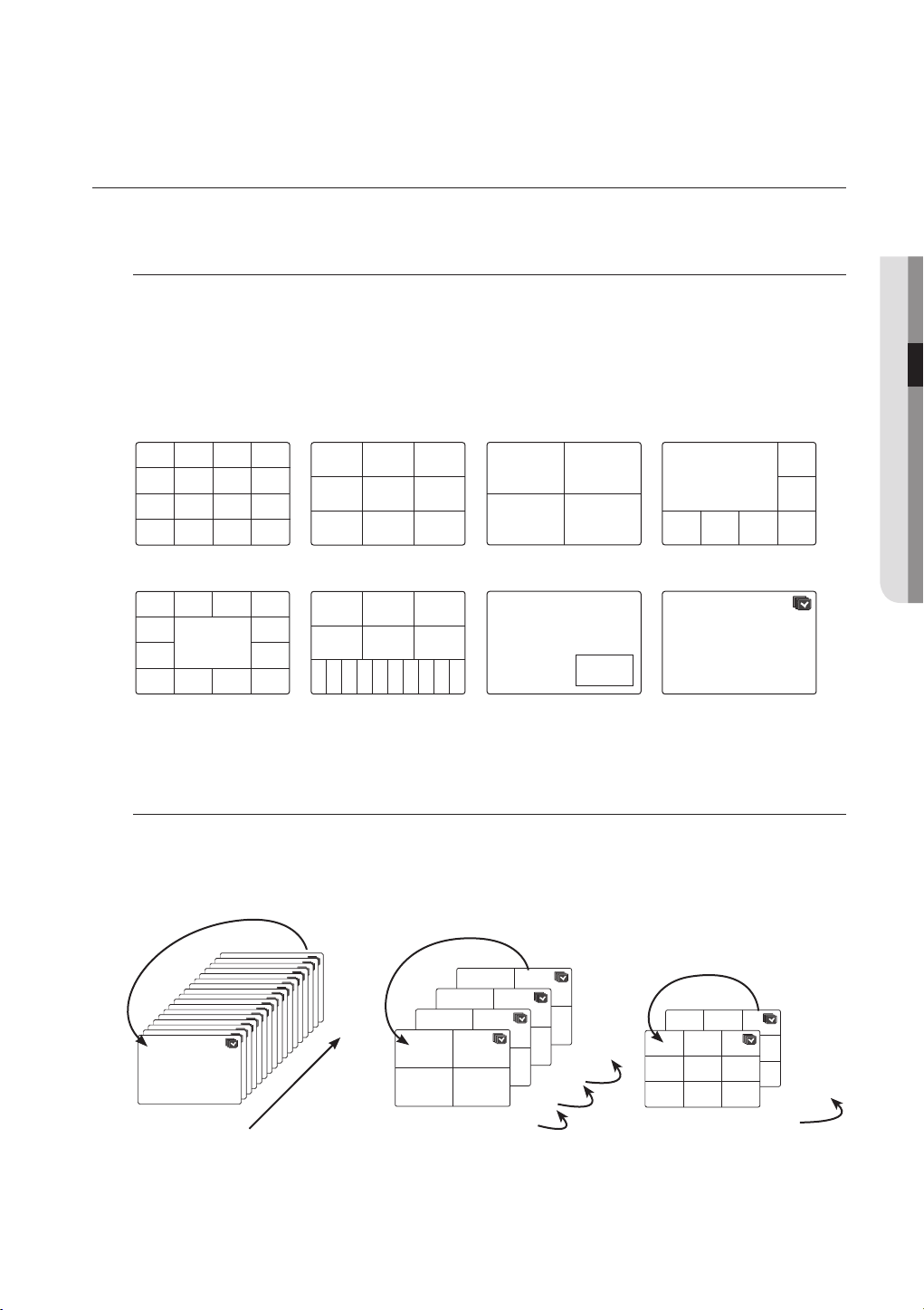
SDR-5102 display Live images from 16 channels in a total of 8 layout of split screens.
Switching the screen mode
To switch the split mode, select a screen mode in the launcher menu, or right-click to select a screen mode in
the context menu.
Press the [MODE] button on the remote control to switch the mode in the sequence of the launcher menu
items.
SDR-4102, SDR-3102 does not support the 16-split screen mode.
`
M
CH3
CH7
CH11
CH4
CH12
CH4
CH8
CH12
CH5
CH7
CH9
CH13
CH2
CH1 CH3
CH4 CH5
CH1 CH3
CH4 CH5
CH10 CH11 CH12 CH13 CH14 CH15 CH16
CH7 CH8 CH9
CH6
CH2
CH6
CH1 CH2
CH1
CH2
CH1
CH1
Auto Sequence
CH2
CH3
CH1
CH2
CH5
CH6
CH9
CH10
16-split mode 9-split mode 4-split mode 7-split mode
CH2 CH3
CH6
CH1
CH8
CH10
CH11
13-split mode 16(A)-split mode PIP
! live
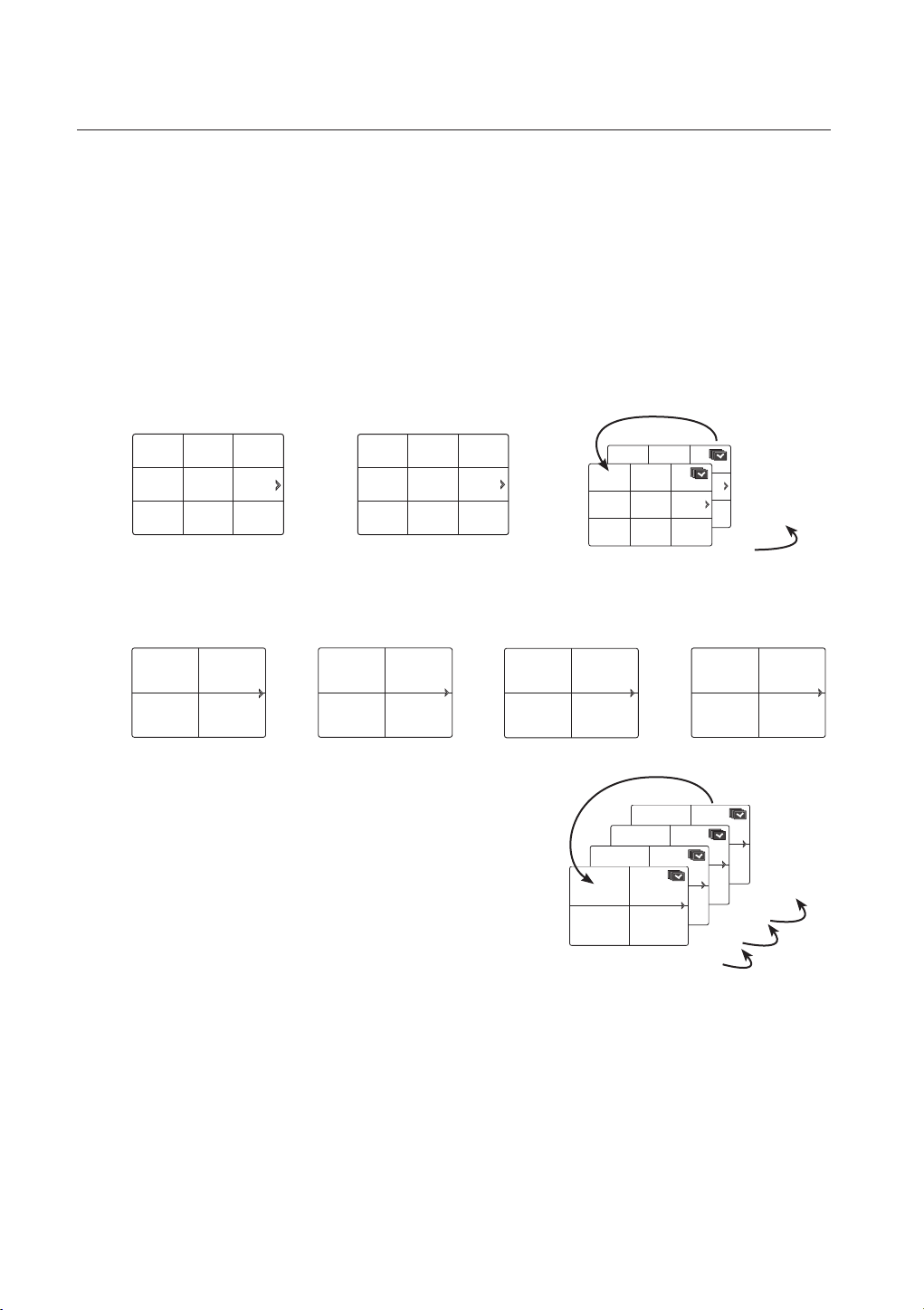
Switching the split mode
SDR-5102 display 16 Live images in the sequence of Single, 4-split and 9-split modes.
Auto Sequence
CH1
CH1
CH1
CH1
CH1
CH1
Single mode
CH1
CH1
CH1
CH1
CH1
CH1
CH1
CH1
1
CH1 CH2
16
CH1 CH2
CH1 CH2
CH3 CH4
CH1 CH2
CH3 CH4
CH3 CH4
CH3 CH4
13-16
9-12
5-8
1-4
4-split mode
CH2
CH1 CH3
CH2
CH1 CH3
CH4 CH5
CH4 CH5
CH7 CH8 CH9
CH7 CH8 CH9
9-split mode
CH6
CH6
10-16
1-9
English _27
live
CH1 CH2
CH3 CH4
CH1 CH3
CH2
CH4 CH5 CH6
CH1 CH2
CH3 CH4
CH1
CH1CH7 CH8
CH4
CH3
CH2
CH5
CH1
CH6 CH12
CH1
CH13
CH19
CH4
CH7
CH5
CH10
CH8
CH11
CH6
CH2 CH3
CH4 CH5
CH2
CH6
CH1 CH3
CH7 CH8 CH9
CH1 CH2
CH3 CH4
CH1
CH4 CH5
CH2
CH6
CH1 CH3
CH7 CH8 CH9
CH1 CH3
CH2
CH4 CH5 CH6
CH1
CH2
CH1 CH2
CH3 CH4
CH1CH7 CH8
CH1
CH13
CH19
CH4
CH7
CH5
CH10
CH8
CH11
CH6
CH2 CH3
CH4 CH5
CH2
CH6
CH1 CH3
CH7 CH8 CH9
CH1 CH2
CH3 CH4
CH1 CH3
CH2
CH4 CH5 CH6
CH1
CH2
CH1 CH2
CH3 CH4
CH1CH7 CH8
CH1
CH13
CH19
CH4
CH7
CH5
CH10
CH8
CH11
CH6
CH2 CH3
CH4 CH5
CH2
CH6
CH1 CH3
CH7 CH8 CH9
CH1 CH2
CH3 CH4
CH1 CH3
CH2
CH4 CH5 CH6
CH1
CH2
CH1 CH3
CH2
CH4 CH5 CH6
CH1 CH2
CH3 CH4
CH1
CH1CH7 CH8
CH4
CH3
CH2
CH5
CH1
CH6 CH12
CH1
CH13
CH19
CH4
CH7
CH5
CH10
CH8
CH11
CH6
CH2 CH3
CH4 CH5
CH2
CH6
CH1 CH3
CH7 CH8 CH9
CH1 CH2
CH3 CH4
CH9 CH10
CH11 CH12
CH13 CH14
CH15 CH16
CH1
CH4 CH5
CH2
CH6
CH1 CH3
CH7 CH8 CH9
CH13 CH14
CH11
CH15
CH10 CH12
CH16
CH1 CH3
CH2
CH4 CH5 CH6
CH1
CH2
CH1 CH2
CH3 CH4
CH1CH7 CH8
CH1
CH13
CH19
CH4
CH7
CH5
CH2
CH6
CH1 CH2
CH3 CH4
CH13 CH14
CH15 CH16
CH2
CH6
CH1 CH3
CH2
CH4 CH5 CH6
CH1
CH2
CH1CH7 CH8
CH1 CH3
CH2
CH4 CH5 CH6
CH2
CH1 CH2
CH3 CH4
CH1CH7 CH8
CH1 CH3
CH2
CH4 CH5 CH6
CH1
CH2
CH1 CH2
CH3 CH4
CH1CH7 CH8
CH1 CH3
CH2
CH4 CH5 CH6
CH1
CH2
CH1 CH2
CH3 CH4
CH1CH7 CH8
CH1 CH3
CH2
CH4 CH5 CH6
CH1
CH2
CH1 CH2
CH3 CH4
CH1CH7 CH8
CH1 CH3
CH2
CH4 CH5 CH6
CH1
CH2
In Single mode, If you have set <SEQ-Dwell Time> in “Setting the Device > Camera”, Auto Sequence will be conducted
`
M
at the set interval. (Page 44)
In a split mode, If you have set <Multi CH SEQ Time> in “Setting the Device > Monitor”, Auto Sequence will be
`
conducted at the set interval. (Page 51)
Manual Switching
Press the left/right button on the remote control, or click the arrow <_/+> key to move to the next split
mode.
• If pressing the right [
9-split (CH 1~9) mode 9-split (CH 10~16) mode Auto Sequence
CH1 CH3
CH4 CH5
CH7 CH8 CH9
• If pressing the right [
Channel (CH 1~4) Channel (CH 5~8) Channel (CH 9~12) Channel (CH 13~16) Auto Sequence
CH1 CH2
CH3 CH4
+
] button in 9-split mode :
CH2
CH6
; ;
+
] button in 4-split mode :
CH5 CH6
; ; ;
CH7 CH8
CH11
CH10 CH12
CH13 CH14
CH16
CH15
CH9 CH10
CH11 CH12
CH1 CH3
CH1 CH3
CH4 CH5
CH4 CH5
CH7 CH8 CH9
CH7 CH8 CH9
CH2
CH2
CH6
CH6
10-16
1-9
CH13 CH14
CH15 CH16
;
CH1 CH2
CH3 CH4
CH1 CH2
CH1 CH2
CH3 CH4
CH1 CH2
CH3 CH4
CH3 CH4
13-16
9-12
5-8
1-4
28_ live
Channel Setting
CH1 CH2
CH3 CH4
CH1CH7 CH8
CH4
CH3
CH2
CH5
CH1
CH6 CH12
CH1
CH13
CH19
CH4
CH7
CH5
CH10
CH8
CH11
CH6
CH2 CH3
CH4 CH5
CH2
CH6
CH1 CH3
CH7 CH8 CH9
CH1 CH2
CH3 CH4
CH5 CH6
CH7 CH8
CH9 CH10
CH11 CH12
CH13 CH14
CH15 CH16
CH1
CH4 CH5
CH2
CH6
CH1 CH3
CH7 CH8 CH9
CH13 CH14
CH11
CH15
CH10 CH12
CH16
CH1 CH3
CH2
CH4 CH5 CH6
CH1
CH2
CH1 CH2
CH3 CH1CH15
CH16
CH13
CH14
CH15
CH11
CH16
CH12
CH7
CH3
CH8
CH4
CH13
CH9
CH14
CH10
CH5
CH1
CH6
CH2
CH1 CH2
CH3 CH4
CH1CH7 CH8
CH4
CH3
CH2
CH5
CH1
CH6 CH12
CH1
CH13
CH19
CH4
CH7
CH5
CH10
CH8
CH11
CH6
CH2 CH3
CH4 CH5
CH2
CH6
CH1 CH3
CH7 CH8 CH9
CH1 CH2
CH3 CH4
CH5 CH6
CH7 CH8
CH9 CH10
CH11 CH12
CH13 CH14
CH15 CH16
CH1
CH4 CH5
CH2
CH6
CH1 CH3
CH7 CH8 CH9
CH13 CH14
CH11
CH15
CH10 CH12
CH16
CH1 CH3
CH2
CH4 CH5 CH6
CH1
CH2
CH1 CH2
CH3 CH1CH15
CH11
CH16
CH12
CH7
CH3
CH8
CH4
CH13
CH9
CH14
CH10
CH5
CH1
CH6
CH2
CH15
CH11
CH16
CH12
CH7
CH3
CH8
CH4
CH13
CH9
CH14
CH10
CH5
CH1
CH6
CH2
CH15
CH16
CH13
CH14
CH1 CH2
CH3 CH4
CH1CH7 CH8
CH4
CH3
CH2
CH5
CH1
CH6 CH12
CH1
CH13
CH19
CH4
CH7
CH5
CH10
CH8
CH11
CH6
CH2 CH3
CH4 CH5
CH2
CH6
CH1 CH3
CH7 CH8 CH9
CH1 CH2
CH3 CH4
CH5 CH6
CH7 CH8
CH9 CH10
CH11 CH12
CH13 CH14
CH15 CH16
CH1
CH4 CH5
CH2
CH6
CH1 CH3
CH7 CH8 CH9
CH13 CH14
CH11
CH15
CH10 CH12
CH16
CH1 CH3
CH2
CH4 CH5 CH6
CH1
CH2
CH1 CH2
CH3 CH1
CH15
CH11
CH16
CH12
CH7
CH3
CH8
CH4
CH13
CH9
CH14
CH10
CH5
CH1
CH6
CH2
CH1 CH2
CH3 CH4
CH1CH7 CH8
CH1
CH13
CH19
CH4
CH7
CH5
CH11
CH2
CH6
CH1 CH2
CH3 CH4
CH9 CH10
CH11 CH12
CH13 CH14
CH15 CH16
CH2
CH6
CH1 CH3
CH2
CH4 CH5 CH6
CH1
CH2
CH1 CH2
CH1CH15
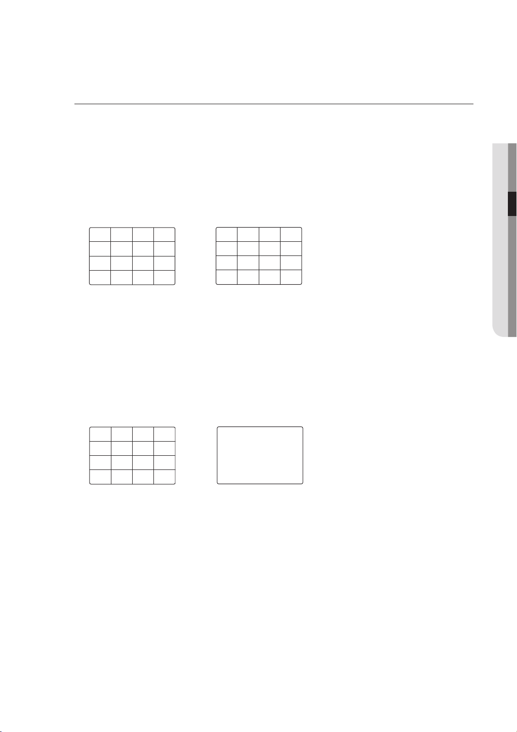
You can display the channel in a desired area of a split screen.
1. Place the cursor over the camera name of each channel to display the <
2. Click a camera name to display a channel list where you can select a different channel.
3. Select a desired channel and click it.
Switching to Single Mode
When in split mode, select and double-click a desired channel to switch to its Single mode.
Press the number corresponding to a desired channel on the remote control to switch to its Single mode.
• CHANNEL 1–9 : Press each button between 1 to 9. (8CH : 8)
• CHANNEL 10 : Press the [0/+10] button.
• CHANNEL 11–16 : Press the [0/+10] button first, then press any number between 1 to 6 within 1 second.
Refer to “Remote Control > Using the numeric buttons”. (Page 12)
Ex : If double-clicking CH 3 or pressing the number “3” on the remote control.
`
%
The current channel will be switched to the selected one.
> key to the right on the screen.
Use the cursor to select a channel to move, and drag and drop it to a desired channel; this can also
change the channel position.
Ex : if switching CH 1 to CH 7
`
CH1
CH5
CH9
CH2
CH6
CH10
CH3
CH7
CH11
CH4
CH8
CH12
;
CH3
CH7
CH5
CH9
CH2
CH6
CH10
CH4
CH1
CH8
CH11
CH12
! live
CH1
CH5
CH9
CH13
CH3
CH7
CH11
CH15
CH4
CH8
CH12
CH16
;
CH3
CH2
CH6
CH10
CH14
English _29
live
2013-01-01 01:10:25
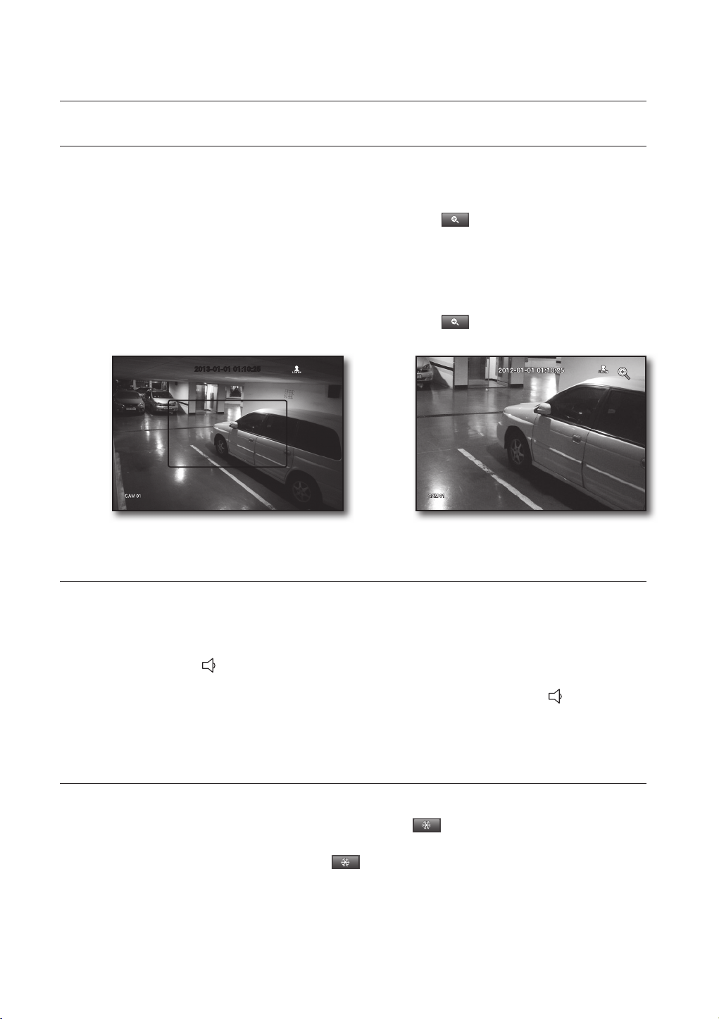
ZOOM
This is available only in Single Live mode. In Single mode, select a desired area and use the Zoom function to
enlarge it twice.
1. Select <Zoom In> in the right-click menu.
Press the [ZOOM] button on the remote control, or simply click <
box appears.
2. Use the direction keys, or drag and drop to specify an area to enlarge.
3. Press the [ENTER] button, or double-click the selected area to enlarge it twice.
In the enlarged image, use the direction buttons ($%_ +) on the remote control to move the enlarged area.
`
4. Press the [ZOOM] button on the remote control, or simply click < > in the launcher menu to release
the zoom.
2013-01-01 01:10:25
;
> in the launcher menu. The zoom
AUDIO ON/OFF
You can turn the sound on/off corresponding to the channel in Live mode.
AUDIO On/Off in Single mode
Click the audio icon (
Only the channel where <Audio> is set to <ON> in “Device > Camera” displays the audio icon ( ) in Live mode that
`
M
you can use to turn the sound on/off.
) on the screen, or press the [AUDIO] button on the remote control to turn it on/off.
FREEZE
This is available only in Live mode, this pauses playing the Live image temporarily.
1. Press the [FREEZE] button on the remote control, or click < > in the launcher menu.
The playback of the image is stopped temporarily.
2. Press the [FREEZE] button again, or click < >.
This will release the freeze.
30_ live
 Loading...