

SAMSUNG SDR_430E.10029.1.15 Service Manual
DVD-ROM DRIVE
SD R-430
DVD-ROM Service
Manual
D V D - R O M D R I V E
C O N T E N T S
1. Precautions
2. Specifications
3. General information
3-1. External part name
3-2. Cricuit description
3-3. Troubleshooting
3-4. IC internal block and IC pin option
4. Disassembly and assembly
5. Alignment and adjustment
6. Exploded views and prats
7. Cricuit Part list
8. Block diagram
9. Electrical board
10. Schematic diagrams

ELEC TRONICS
¨Ï Samsung Electronics Co., Ltd.October.1998
Pr inted in Korea

1. Precaution s
1-1. General items
1) Be careful not to have eyes or a part of
body touch with laser diode at repair because
this product uses laser diode.
2) Do not disassemble Pick-up at repair.
If the laser diode is bad, replace the
entire Pick-up.
3) Keep away from TV or other electrical units
at repair to prevent a influence from
surrounding units.
4) If you want to replace the parts during
repair, be sure to plug off power cable
before replacement.
5) If you insert a disc into CD player, beg
sure to load it correctly.
1-2. Electricity sensing device
Some semiconductor units may be damaged easily by
electricity. These elements are called as electricity
sensing device(ESD) in general. For example,
integrated circuit, field effect transister,
semiconduct chip.
The following methods have to be used to reduce the
accident of element damage generated by electricity.
1) Emit all electric charges in your body through
contact with earthing materail at once before
handling a semiconductor factor or device
including it.
In other way, make use of commercial wristlet
against electRIC1ty. It shall be detached before
power impression to the unit on testing because
of shock.
2) After detaching an electrical device including
ESD, it shall be placed on conductive urface such
as aluminium to prevent the charge acummulation
and unit exposure.
3) Utilize only the soldering iron with earthed end
for ESD soldering or release.
4) Make use of only anti-static soldering release
unit. A soldering release unit not to be
classified as anti-static may generate the enough
charge to damage ESD unit.
5) Never use a Freon-propelling chemical product.
It may generate the enough charge to damage ESD.
6) Because this unit can't be used by itself, surely
mount it on PC(pentium or more) and check the
operations in use of private device drive floppy
diskettd. Refer to Instruction manual.
7) This unit has many parts with features related to
safety and especially, for essential parts, the
importance is indicated on circuit diagram and part
list. Be certain to use the parts with same
specifications at replacing these parts.
6) Untill installing ESD unit for replacement, never
it from protection package.(Most of ESD unit for
replacement have lead composed of package shorted
electrically by conductive foam, aluminium or
similar conductive material.
7) Contact with shassis including ESD or protection
material in circuit parts hust before detaching the
protection meterial from lead of ESD unit for
replacement.
NOTE: Be sure to avoid the power impression
to the shassis or circuit and observe the safey
instruction
8) Minimize the body action at handling an unpacked
ESD unit for replacement.
(Otherwise, an unconscious action, so to speak,
friction between clothes or foot lifting from
carpet floor may generate the enough charge to
damage ESD unit.)
Samsung Electronics
1-1

1-3. Safety instructions
1) Read all safety and operational manuals before
operating this product.
2) Keep the safety and operational manuals for future
reference.
3) Observe all precations and operational instuctions
in or on the suface of this product.
4) Follow all operation and maintenance cautions.
5) Be sure to plug off the power cable before cleaning. Use a dry cloh to clean a dusty cover of
cabinet instead of Instead of liquid or aersol
cleaner.
6) Never use a attachment not to be recommended
by this company. It may result in danger and
damage.
7) Never use this product around water such as
bathtub, washbasin, laundry machine, swimming
pool or lakeside.
8) Never place this product on bed, sofa or around
radiator and heater.
9) Power : Utilize the only power displayed on lebel
If the power type can't be checked, call to dealer of Korea Electricity, Co, Ltd. Refer to operate this product by battery or other power.
10)Lightning : Plug off the power cable for product
protection during thunder and lightning flashes or
this product is unused for a long time.
11) Overload: Be careful that the wall outlet and
expanded cord is overloaded due to danger of
fire and electric shock.
12) Never insert a substance or liquid into this
prouct. It may cause fire or shorck by contact
with voltage point or short.
13) Part replacement : The service engineer has to
use the parts of same specification at replacement. Otherwire, Otherwire, fire, shock or other
dangers may be occurred.
14) Safety check : Be sure to perform the safety
check at service or repair completion.
Im portance
:
This product includes special impotrant
parts on safety. These parts are indicated
by on schematic diagram.
At replacement of these parts, use the
parts of same specification due to shock,
fire or other dangers.
Never transform the original design
without permission of this company.
1-4. Earthing cautions at handling Pick-up
Because the laser diode in optical Pick-up is subject
to get out of order due to the potential difference
occurring by electricity load charged in clothes or
bodies, observe the following eathing items at
handling.
1) Body earthing at repair : Be sure to wear a wrist
strip with one side earthed.(Impedance : Below
4
10§Ù). It removes the electicity formed in body.
2) Wire table earthing : Put the earthed conductive
Plate(Impedance : Below 10§Ù)such as copper plate
on work table.
4
3) Cautions for clothes : Do not have any clothes is
destroyed easily.
4) FPCB operation be careful to handle FPCB because
it may be damaged easily.
1-2
Samsung Electronics
2. Specifications
The specification and design may be altered without previous notice and the below weight and dimensions
are approximate values.
Drive type Computer built-in
Power consumption Dc + 5V, 1A DC + 12V, 1.5A(MAX)
General
option
Electrical
feature
Weight 930g
Dimension 149mm(W)¡¿200mm(D)¡¿415mm(H)
Allowable operational
temperature
+5¡É ~ +45¡É
Allowable operational humidity: 8% ~ 80%
Standard mode CD-ROM Mode 1,2
Interface ATAPI BUS (IDE)
Data transfer rate CD-ROM:4,800Kbyte/sec,DVD-ROM:6,480Kbyte/sec
ACCESS
TIME
CD-ROM
1/3 stoke Below : 110ms
full stoke Below : 200ms
1/3 stoke Below : 130ms
CD-ROM
full stoke Below : 200ms
Buffer capacity 512KB
-12
-9
Error ratio
Mode 1 : Below 10
CD-ROM
Mode 1 : Below 10
DVD-ROM Below 10
-15
Frequency response 20Hz to 2KHz : Below ¡¾ 3dB
Sign al to noise ratio
Distortion factor Below 0.15% (1KHz)
Signal output level
Lase Semiconductor laser
Samsung Electronics
LINE OUT over : 75dB
H/PHONE over : 65dB
LINE OUT : 0.7Vrms ¡¾ 20%
H/PHONE : 0.6Vrms ¡¾ 20%
2-1
4. Disassembly and assembly
4-1. Exterior and PCB disass embly
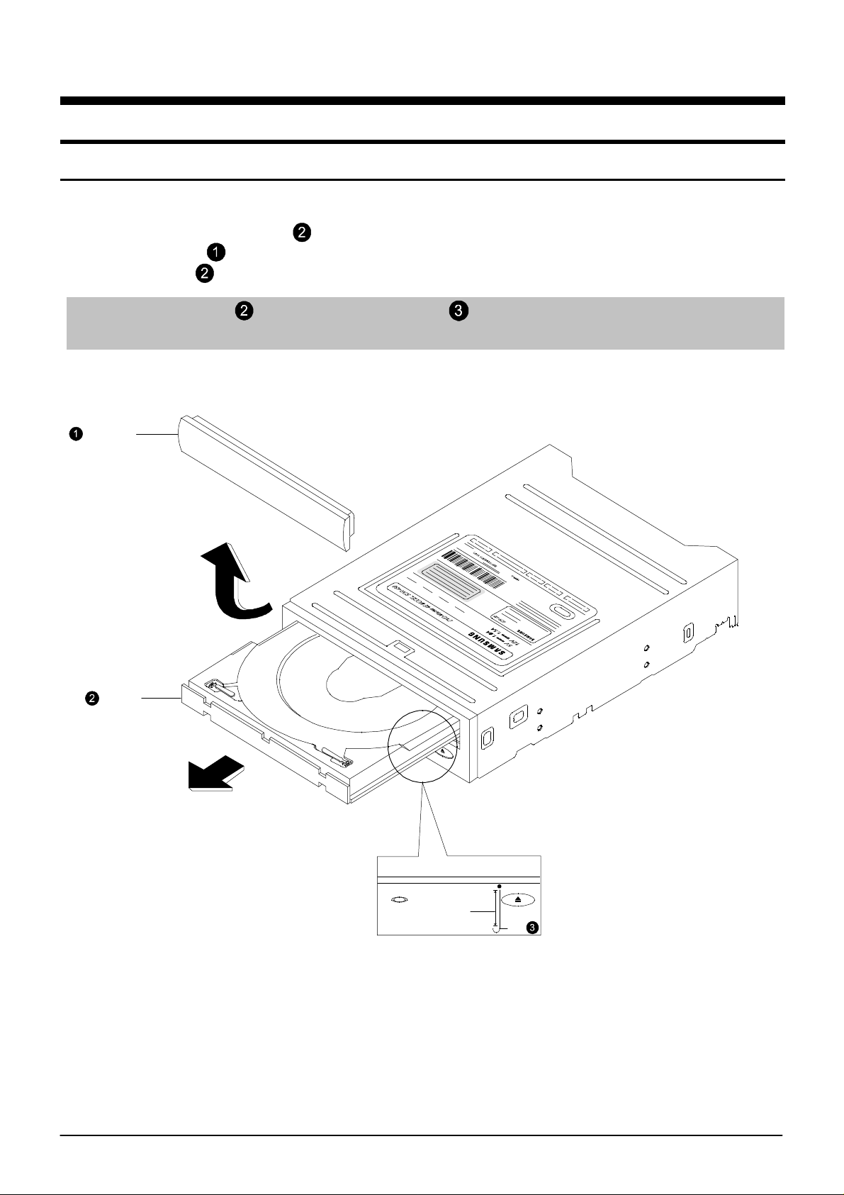
4-1-1 Door-tray
1) Supply power to open the tray in direction of arrow "A"
2) Lift up the door in direction of arrow "B"
3) Close the tray and power off.
Reference: If the tray doesn't open, push the clip into specified hole shown in detailed figure
to open it compulsorily.
DOOR
¡°B¡±
TRAY
¡°A¡±
BYSY
70mm
CLIP
Figure 4-1 Door tray
4-1
Samsung Electronics
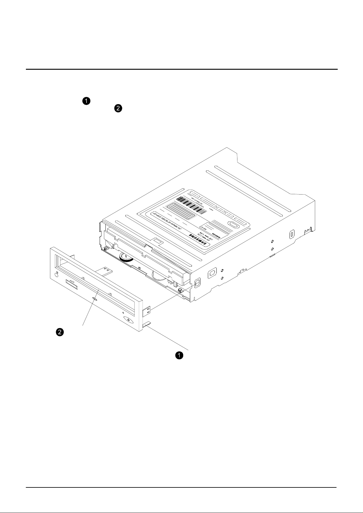
4-1-2 Panel front
1) Remove 5 hooks
2) Take out the panel-front forward.
Disassembly and assembly
Panel-front
Samsung Electronics
5 Hooks
Figure 4-2 Panel-front
4-2
Disassembly and assembly
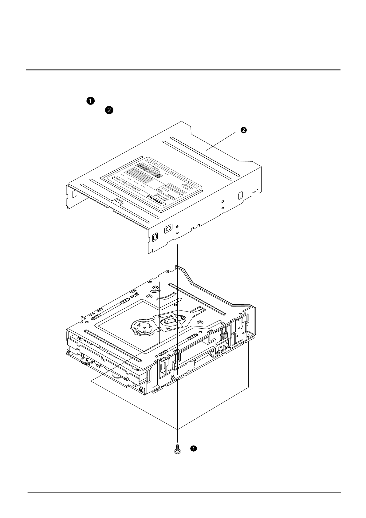
4-1-3 Top-cabinet
1) Remove 4 screws in the bottom
2) Lift up the top-cabinet
Top-cabinet
4-3
4 Screws
Figure 4-3 Top-cabinet
Samsung Electronics
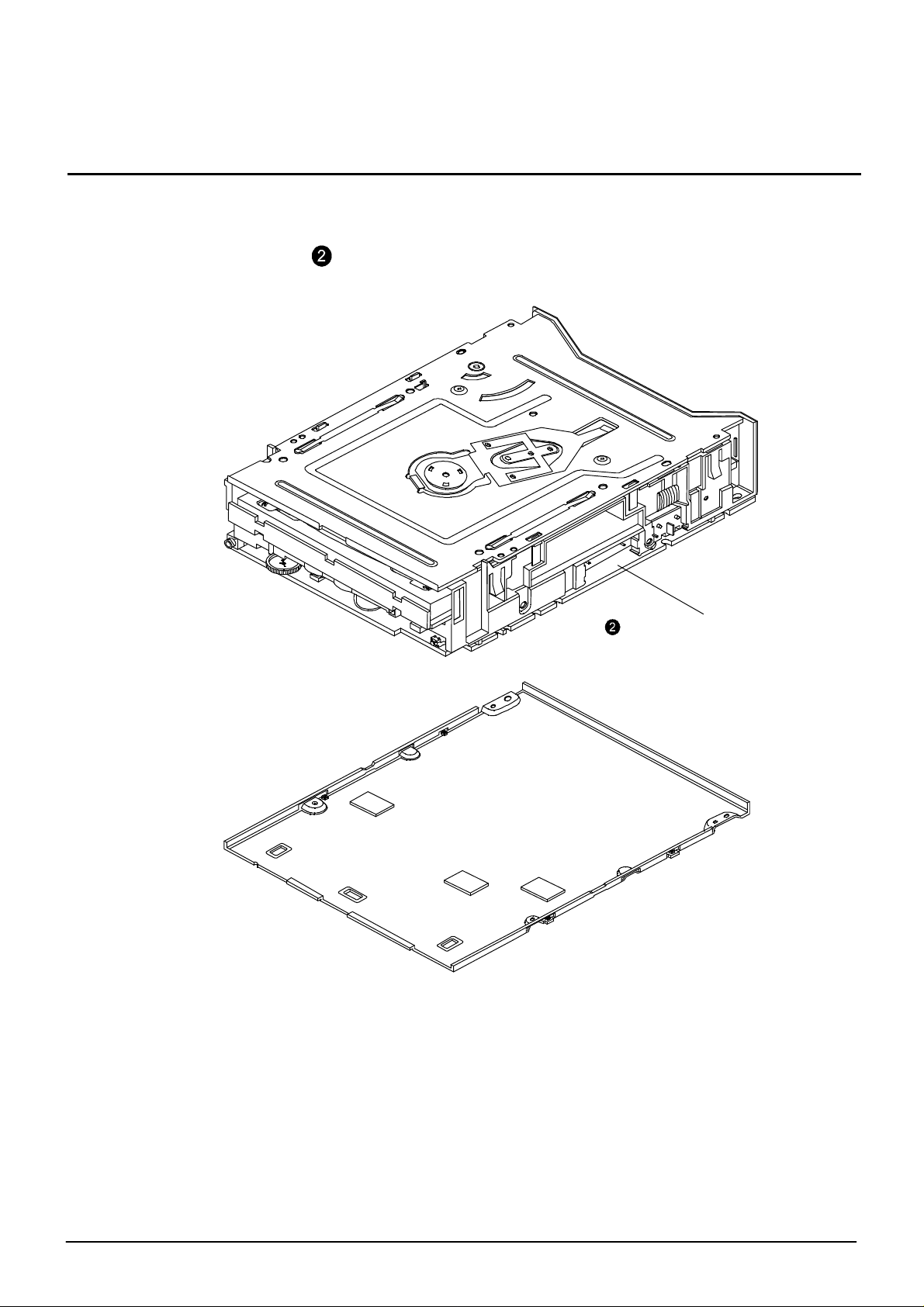
4-1-4 Ass'y-frame Low
1) Lift up the ass'y frame low
Disassembly and assembly
Ass'y frame Low
Samsung Electronics
Figure 4-4 Ass'y-frame Low
4-4
Disassembly and assembly
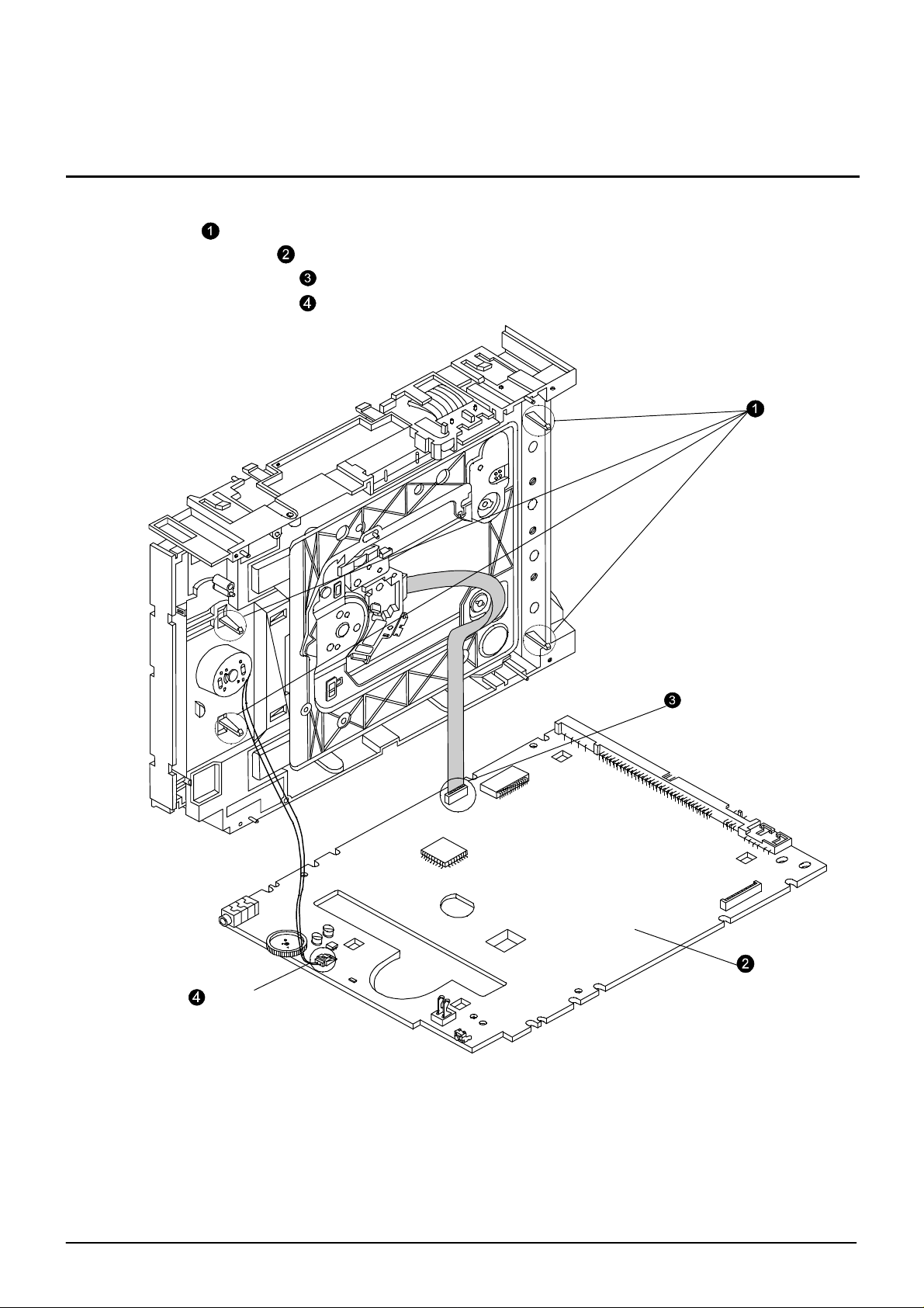
4-1-5 MAIN-PCB
1) Remove 4 hooks for PCB fixing in deck.
2) Disassemble the MAIN-PCB
3) Disassemble the pick up FPC in PCB.
4) Disassemble the motor wire in PCB.
4 hooks
MOTOR Wire
Pick up FPC
PCB-MAIN
4- 5
Figure 4-5 Disassembly connector
Samsung Electronics
4-3. Deck disassembly
4-3-1 Tray, Clamper
1) Remove 4 screws
2) Remove 4 hooks
3) Lift up the ass'y clamper
4) Lit up the tray
4 screws
Ass'y clamper
Tray
4 hooks
Samsung Electronics
Figure 4-6 Tray
4- 6
Disassembly and assembly
4-3-2 Ass'y-Deck DVD
1) Move the slide cam in left direction.
2) Remove the HOLDER FPC and disassemble the DECK FPC.
3) Disassemble the ass'y-deck DVD in arrow "B" direction with pushing the 2hooks in direction
of arrow "A"
Ass'y-Deck DVD
Slide cam
"B"
HOLDER FPC
¡°A¡±
hook
<Detailed figure>
4-7
Figure 4-7 Ass'y-Deck DVD
Samsung Electronics
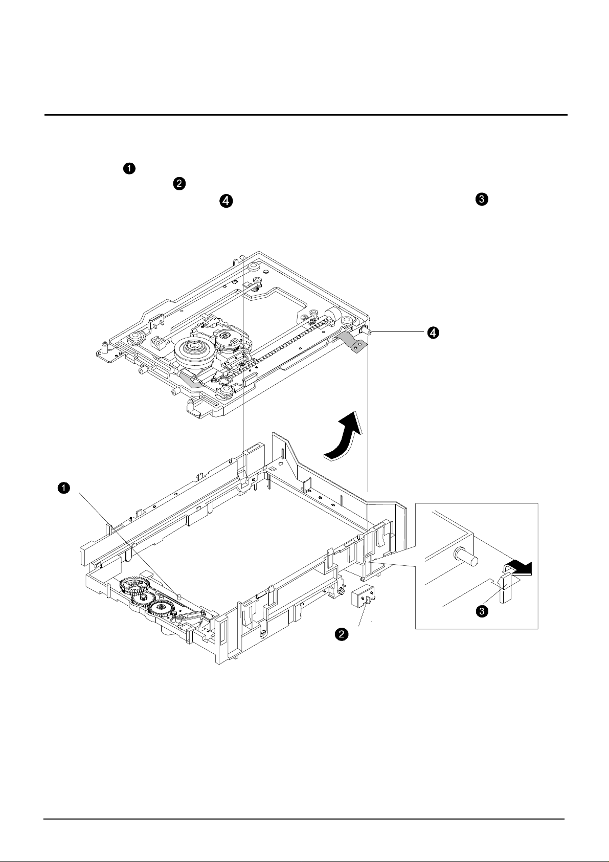
Disassembly and assembly
4-3-3 Chassis-main individual materials
1) Remove screw , and lift up the GEAR TRAY
2) Lift up the GEAR B
3) Remove screw , and lift up the GEAR A , GEAR D
4) Remove screw , and lift up the ASSS'Y OPEN LEVER
5) Remove screw , and lift up the SLIDE CAM
6) Remove 2 screws , and remove the MOTOR ASS'Y in "A" direction
ASS'Y OPEN LEVER
GEAR A
GEAR TRAY
GEAR D
GEAR B
2Screws
¡°A¡±
SLIDE CAM
MOTOR ASS'Y
¢Ä Assemblingthe motor and pulley: The height of
pulley shall be same as the endd of motor shaft.
Samsung Electronics
Figure 4-8 Chassis-main individual materials
4- 8
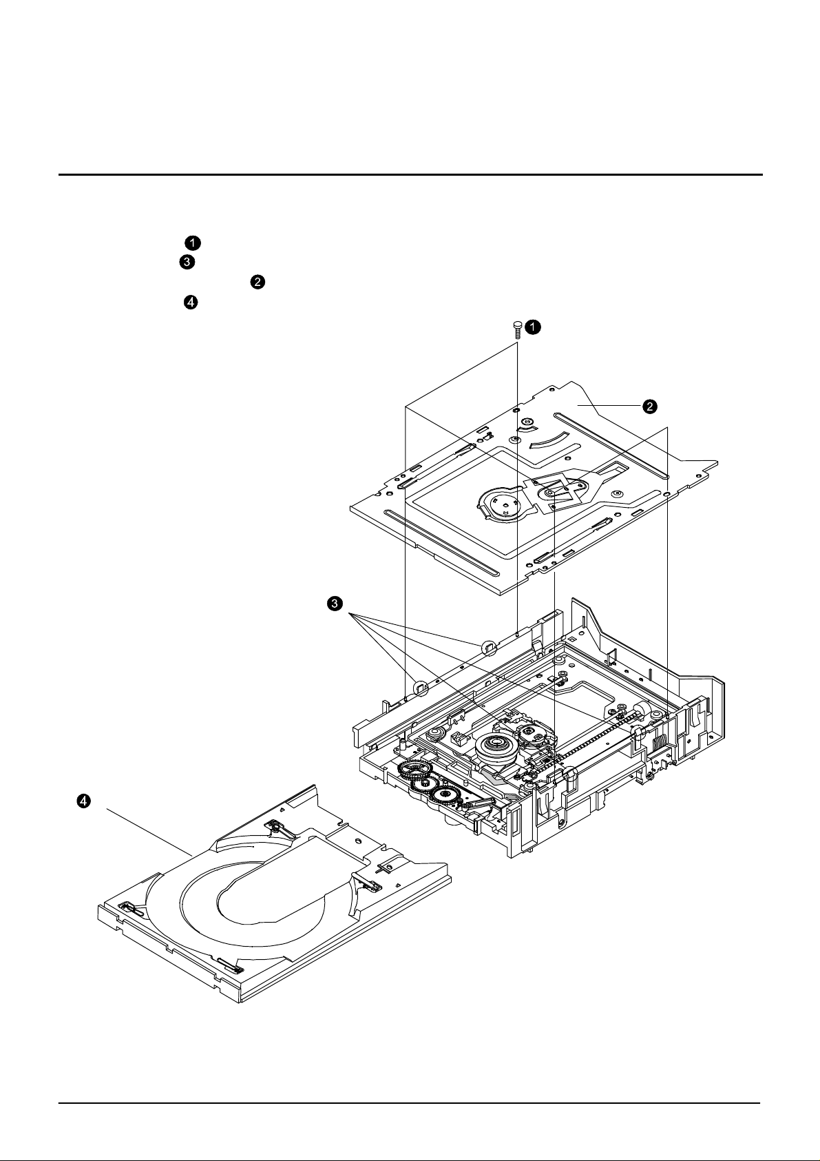
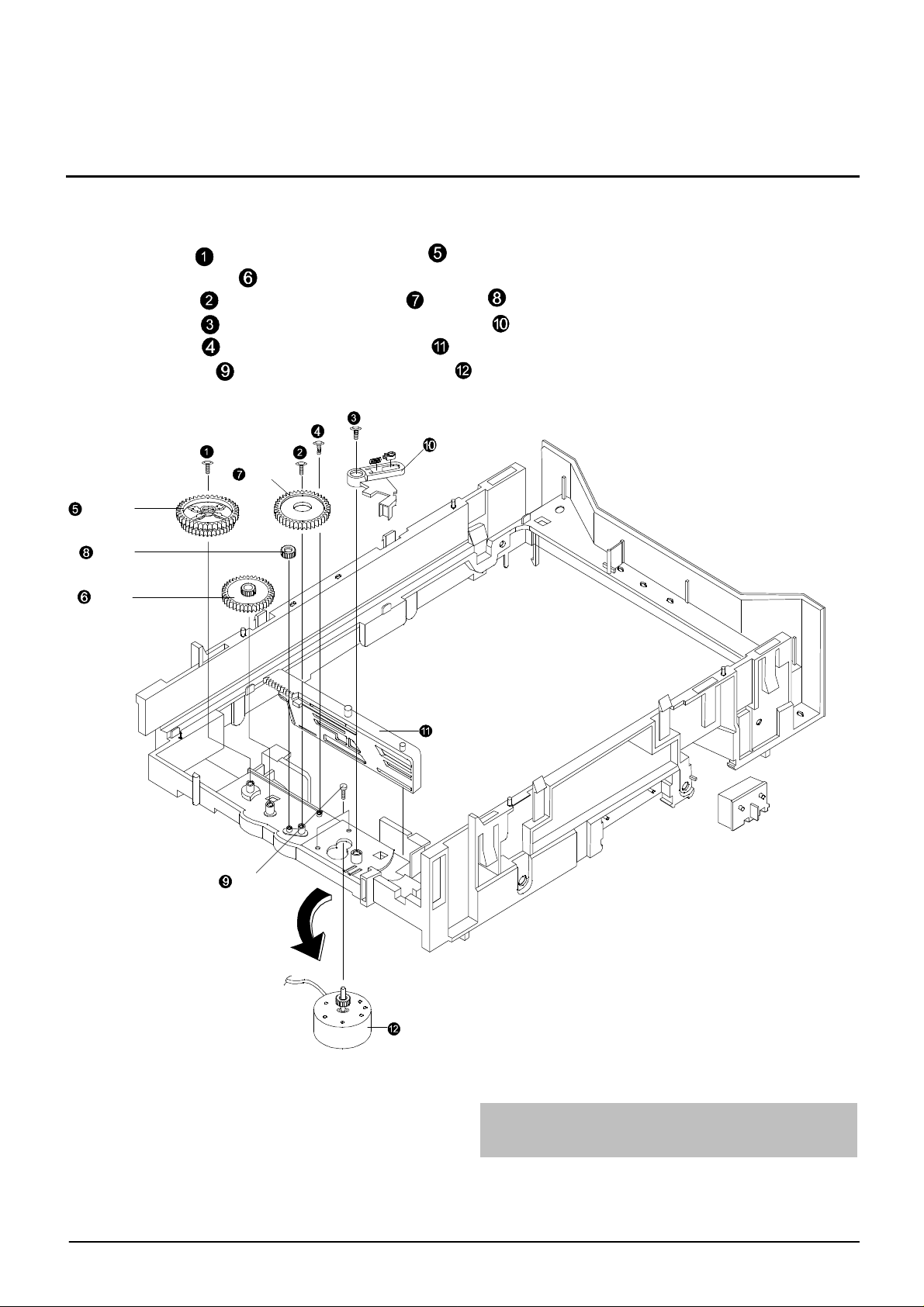
4-3-4 Ass'y-deck
1) Remove 4 screws
2) Lift up the ass'y-deck
3) Remove the pick-up FPC in "A"
Disassembly and assembly
Pick up FPC
¡°A¡±
DECK FPC
Ass'y-deck
4-9
Figure 4-9 Ass'y-deck
Samsung Electronics

Disassembly and assembly
4-3-5 Ass'y-deck individual materials
1) Remove 4 dampers
2) Rotate 180¡£ the SHAFT COVER in CCW direction.
3) Lift up the ass'y
4) Remove 2 screws , and remove the 2 CAMs , and lift up P/U
5) Remove 3 screws , and removev the MOTOR SPINDLE , and disassemble the DECK-FPC
6) Remove soldering "A",¡°B¡± in deck-FPC, and remove the S?W
7) Remove the DECK FPC
8) Remove 4 screws , and disassemble the HOLDER MOTOR in the STEP MOTOR in "C" direction
9) Remove 1 screw , and disassemble the spring plate
10) Remove the shaft P/U in "D"direction, and remove 1 screw ,and disassemble the ass'y slide
step
11) Remove 2 hooks in ASS'Y SLIDE STEP, and remove the slide step
SHAFT P/U
1 screw
¡°D¡±
SHAFT COVER
SPRING PLATE
ASS'Y
SHAFT P/U
1 screw
SLIDE STEP
³ª»ç 2°³
2 CAMs
SLIDE
STEP
¡°A¡±
¡°C¡±
HOLDER MOTOR
4screws
¡°B¡±
S/W
4 dampers
MOTOR SPINDLE
DECK FPC
3 screw
Figure 4-10 Ass'y-deck individual materials
4- 10Samsung electronics

5. PLL ADJUSTMENT
5-1. PLL adjustment( FOR DVD)
1) Insert DVD disk, make it full stroke on CDT. Making use of SVR1, and then turn it CW with athe
controller. Next turn VR CCW at the point ¨Í of stoping stroke. Again check up the point ¨Î of stoping
stroke VR ¨Î located between point ¨Í and ¨Î. VR is lied halfway between two point.
ex)
¨Íposition
ccw
<After adjustment position>
¨Îposition
<M AIN-PCB:operational position diagram>
5-1
Samsung electronics
3. General information
3-1. Circuit descr iption
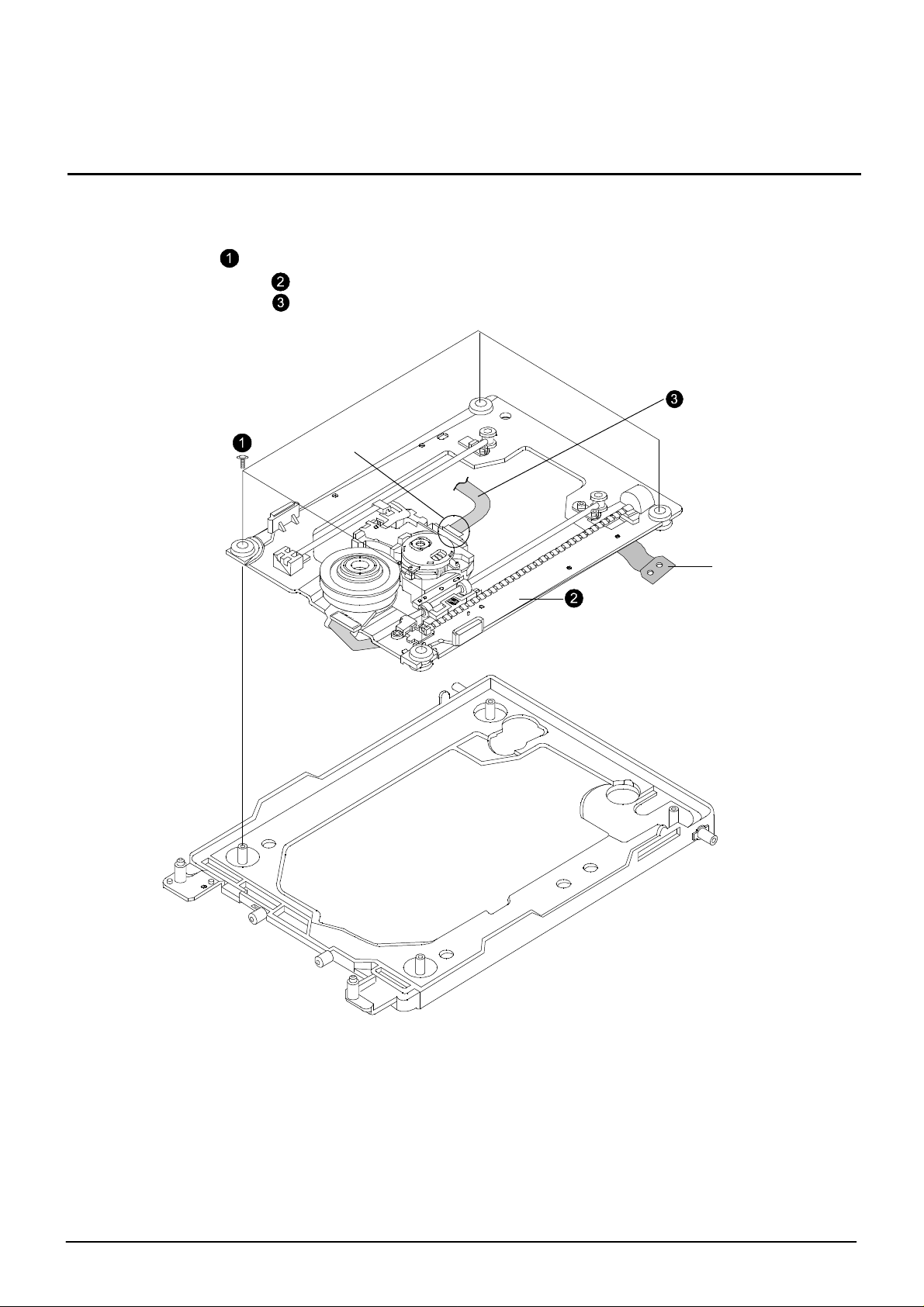
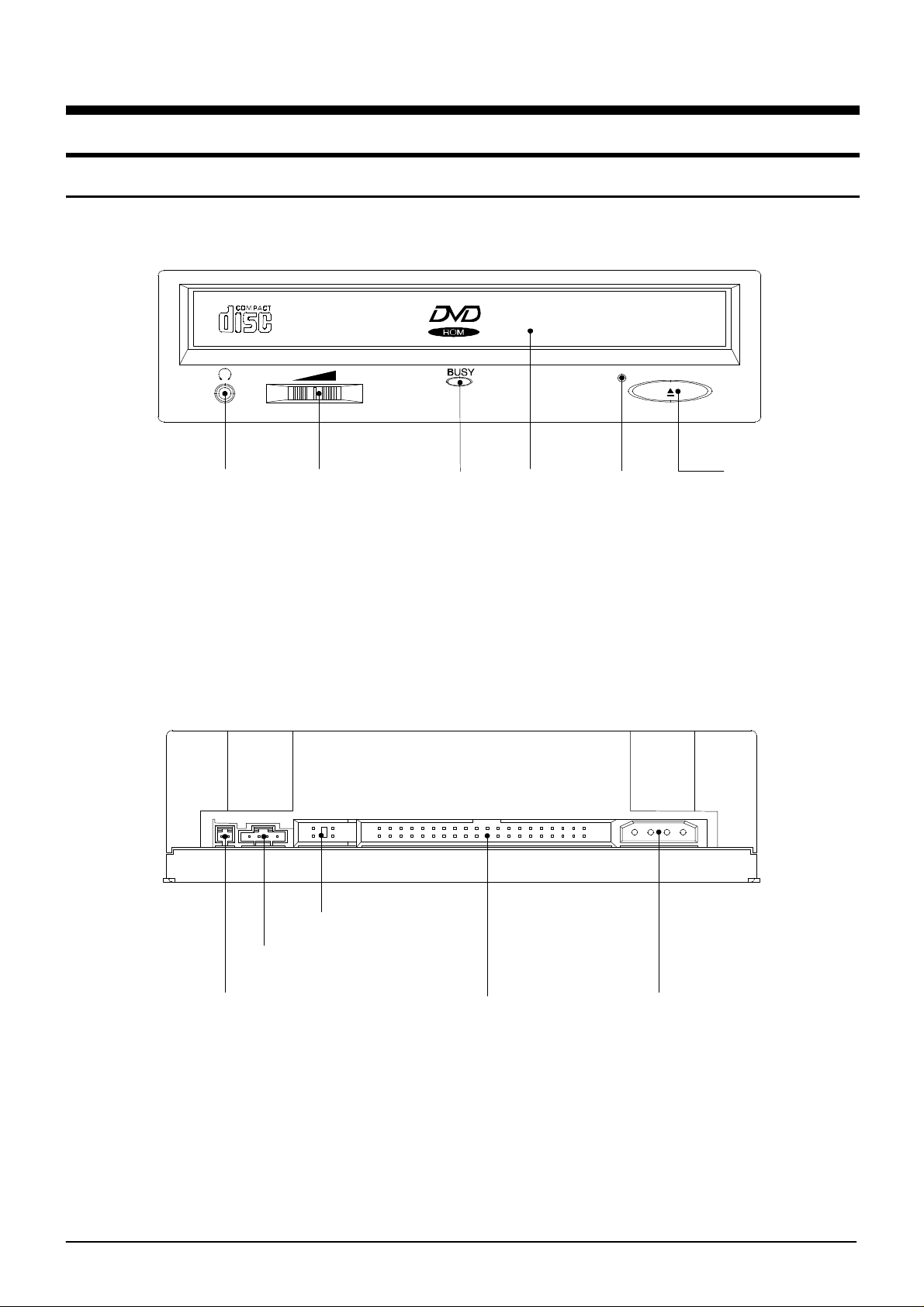
3-1-1. Front
3-1-2. Rear
Earphone
jack
Up/Down
Volume
LED Disc tray Emergency
Figure 3-1
Stop/ Open
button
HOLE
Digital output
terminal
(Optional)
Samsung Electronics
Sound output
terminal
Master/Slave
select pin
Interface terminal
Figure 3-2
Power terminal
3-1
3-2. Circuit descr iption
3-2-1. RF
3-2-1(A) RIC1(TA1293F)
RIC1(TA1293F)is used in combination with TC 9453F as bipolar IC developed for CD/DVD RF signal
system. In main, it receives the pick-up output converted into I/V and performs DVD waveform equalization(EQ), CD equalization(EQ), astigmatic focus error signal generation, 1-beam tracking error
signal generation(by DPD method), 3-beam tracking error signal generation FE TE RF GAIN adjutment and laser power control, etc.
1) Reference potentiometer
RIC1 selects a single power method and from pick-up input singnal terminl works on the basis
VrA of 2.1.V.
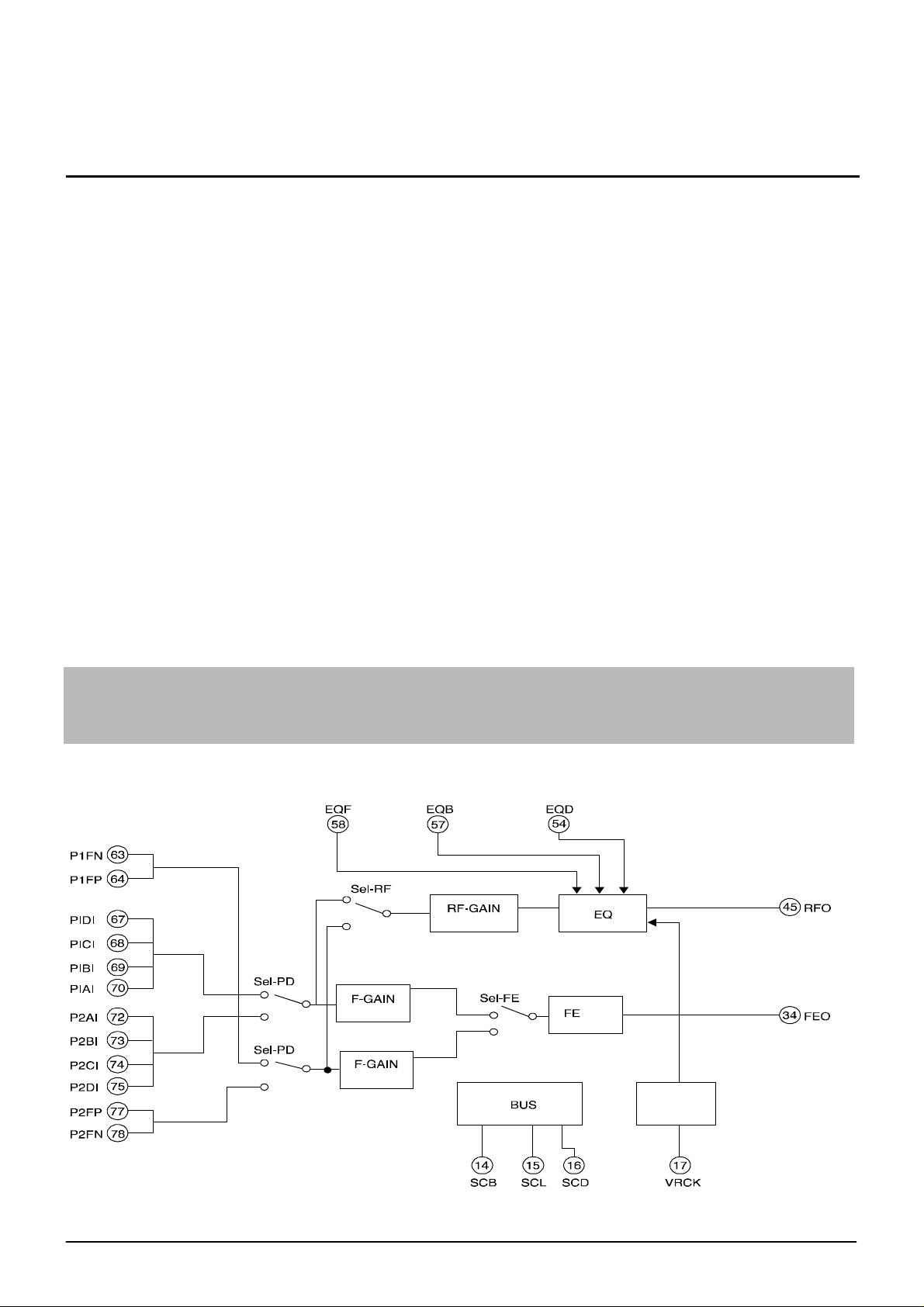
2) CD/DVD-RF signal system : RICL(TA1293F)
Figure 3-3 shows the flow of RF signal generated in pick-up.
¡Ü EQ control parameter
1. EGF(58pin) : Change the peak frequency with EQ frequency features.
(Convert PWM signal, (C9453F(168-pin) into DC via low-pass fiter and supply it.)
2. EGF(57pin) : Change the boost of EQ frequency features.
3. VRCK(17pin) : Input the base clock and link the peak frequency witt it.
4. EQD(24pin) : Change the group delay characteristics with EQ frequency features.
CD/DVD play signal is equalized according to the above control parameter setting and output to
RFD(45pin) and this signal is transferred to TC9453F and detected as digital signal.
3-2
Figure 3-3
Samsung Electronics

Circuit description
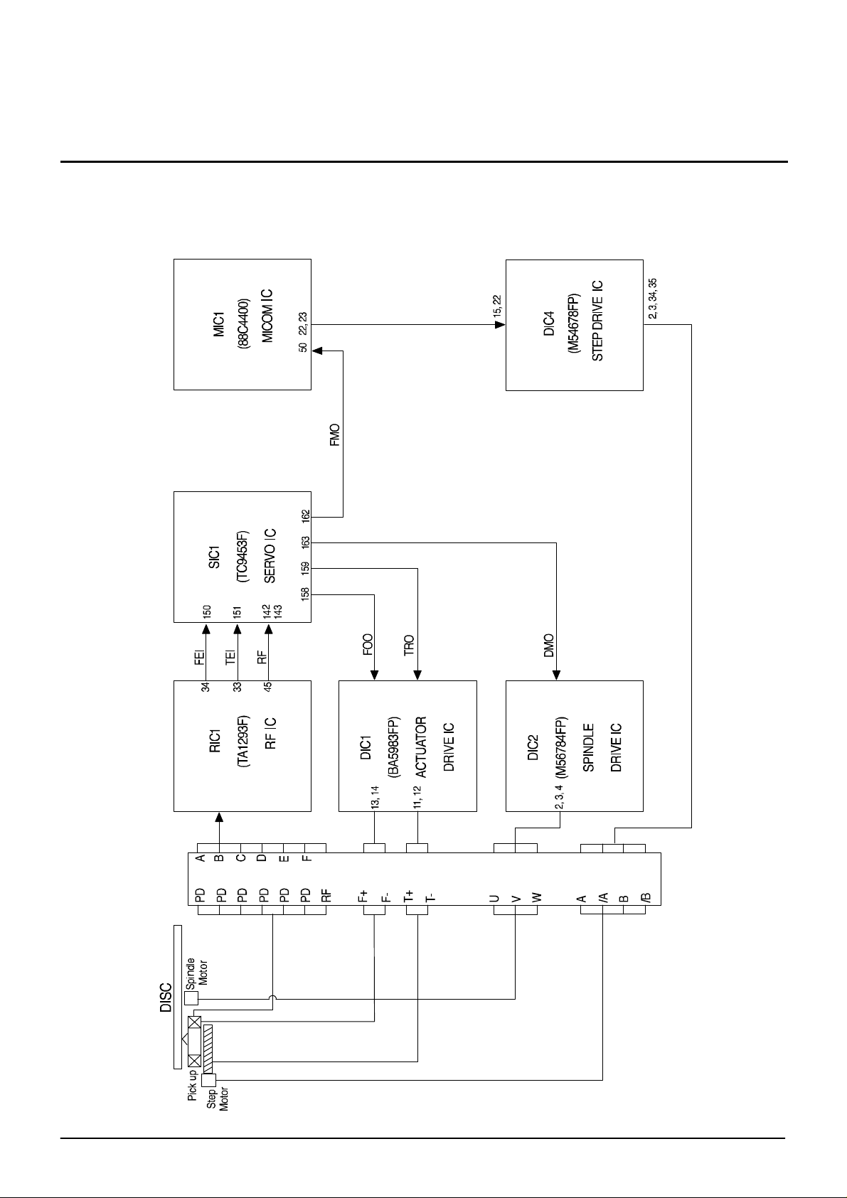
3-3-3. SERVO circuit descrip tion
3-2-2(A) Outline
SERVO system of DVD is divided into FOCUS SERVO, TRACKING SERVO, STEP MOTOR LINKED SERVO
and SPINDLE MOTOR CONTROL SERVO.
1) FOCUS SERVO
Focus the optical spot outputted from object lens on disc surface correctly by maintaining a regular distance beween object lens of Pick-up and disc for surface vibration of disc.
2) TRACKING SERVO
Make the object lens follow the disc track in use of tracking error signal created from Pick-up.
3) STEP MOTOR LINKED SERVO
When the tracking actuator inclines to outer as the object lens follow the track at play, move
STEP motor a little. and prevent it from leaning.
4) SPINDLE MOTOR CONTROL SERVO
Control the disc motor to maintain a constant angular velocity in use of FG signal outted in Drive
IC.
Samsung Electronics
3-3
Circuit description
3-2-2(B) SERVO SYSTEM BLOCK DIAGRAM
3-4
Figure 3-4
Samsung Electronics
Circuit description
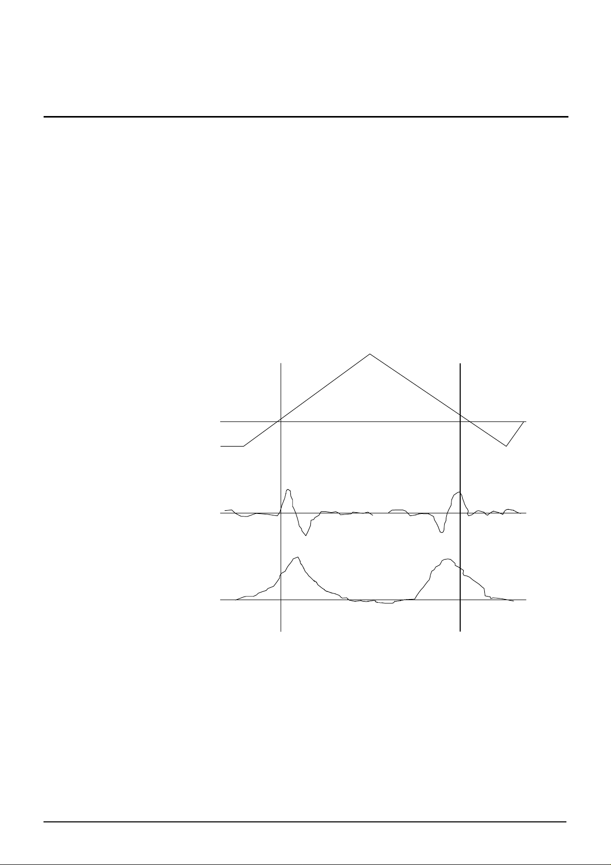
3-2-2(C) Operation descriptions
1) Focusing SERVO
(1)Focus input
The focus loop is changed from open loop to close loop. The triangular waveform moves the object lens up and down in 158pin terminal of SIC1 at Focus SERVO ON. At that time, S curve is
inputted to 150 pin terminal of SIC1. SBAD (152pin terminal of SIC1) signal, summing signal of
PD A, B, C, D, is gernerated at occurrence of S curve and zero cross(1.7V)point is found by S
curve and focused on when SBAD signal exceeds a regular value. The focus loop is changed into
close loop and the object lens follows the moving of disc, maintaining a regular distance with disc.
While, this operations are same in CD and DVD.
158pin terminal of SIC1(FOO)
150pin terminal of SIC1(FEI)
152pin terminal of SIC1(SBAD)
Figure 3-5
(2)Play
When focus loop gets to close loop at focus servo on, both 150pin and 158pin terminal of SIC1
are contolled by Vref voltage(approx.1.7V)and focus on cascade on the disc up and down.
Ve rf
Ve rf
1V
Samsung Electronics
3-5
 Loading...