

Samsung SDH-C75080, SDH-B73040, SDH-C75100, SDH-B7302, SDH-C74040 Quick Network Setup Manual
Page 1
English-1
Quick Network Setup Guide
Connecting to the network using a router
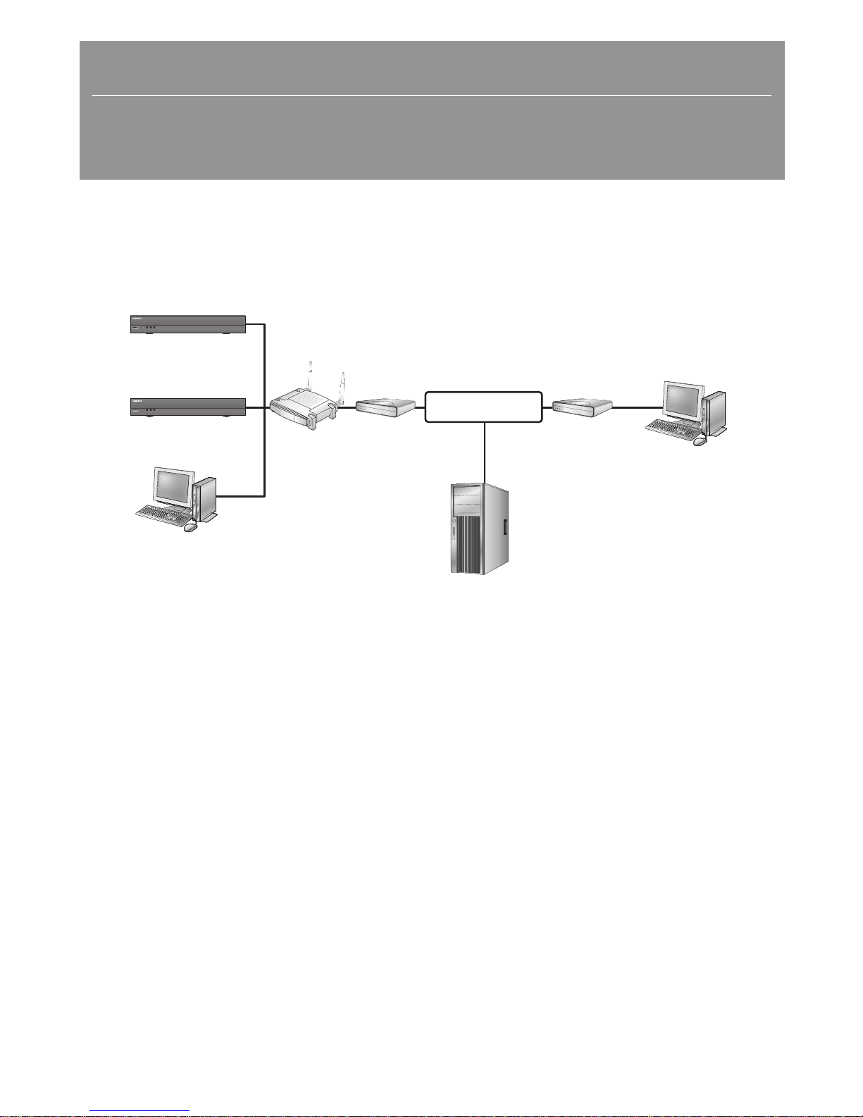
By using a router, you can connect your computer and 1 ~ 3 DVR machines to the internet by sharing 1 internet connection via
xDSL or cable modem.
This installation guide aims at casual users, not for network professionals.
For proper use of the router, strictly follow the steps 1 to 5.
Configure your router, computer and DVR equipments as described in the following steps.
Step 1. Connecting Cables
Step 2. Connecting your local computer to the router
Step 3. Connecting DVR to the router
Step 4. Connecting the router to the internet service line
Step 5. Configuring router’s port forwarding
Step 6. Accessing DVR using DDNS service in dynamic IP environment
DV25
SRN-475S
REC LANPOWER
USB
DV25
SRN-475S
REC LANPOWER
USB
DVR
DVR
Local PC
IP Sharer
xDSL or
Cable Modem
xDSL or
Cable Modem
External
Remote PC
DDNS Server
(www.samsungipolis.com)
INTERNET
Page 2
English-2
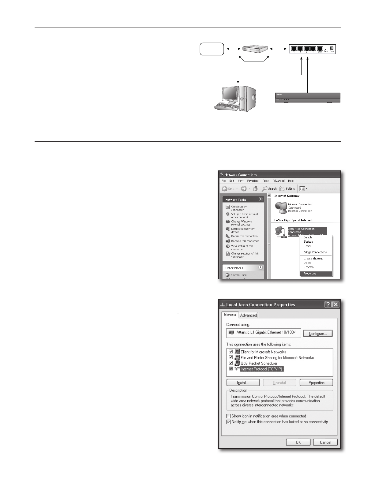
Step 1. Connecting Cables
1. Connect the internet service line (xDSL/Cable Modem)
to your router’s Internet (WAN) port.
2. Connect Ethernet cables from your computer and
DVRs to the LAN (1 to 4) ports of the router.
Step 2. Connecting your local computer to the router
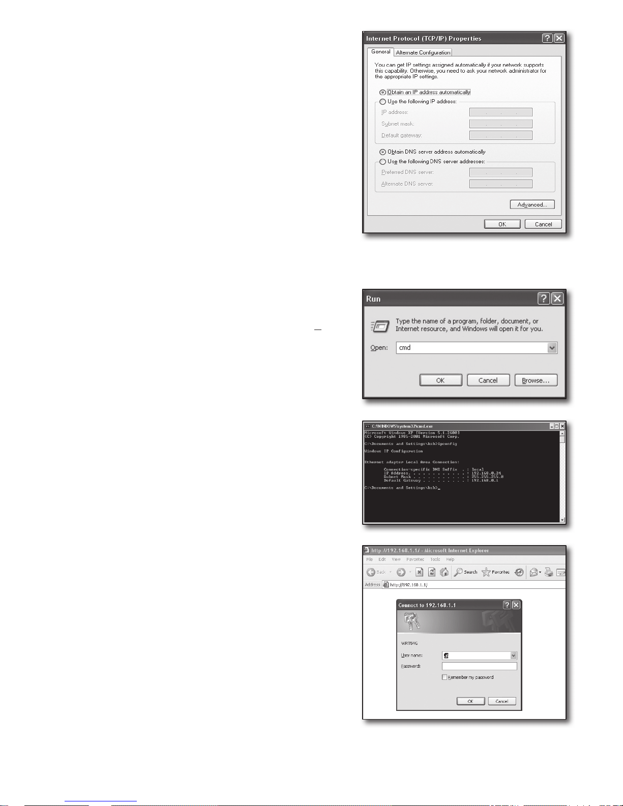
Step 2.1 Connection Setup
1. Click [Start] on your computer.
2. Open the <Control Panel>-<Network Connections>.
The “Network Connections” window appears.
3. Select <Local Area Connection> and right click on it.
4. Select <Properties>.
5. “Local Area Connection Properties” window appears.
6. Select <Internet Protocol (TCP/IP)> and click [Properties]
button.
DV25
SRN-475S
REC LAN POWER
USB
Broadband Router
Cable/ADSL/VDSL
Direct LAN
(Dynamic/Static IP)
INTERNET
or
DDNS Server
(www.samsungipolis.com)
Local PC
DVR
Page 3
English-3
7. Select <Obtain an IP address automatically> and <Obtain
DNS server address automatically>, and click [OK] button.
8. Click [OK] button to finish the setup.
Step 2.2 Confirming the Connection
1. Click [Start] on your computer.
2. Click [Run…].
3. On the appeared command dialog, type ‘cmd’ in the <Open>
box and click [OK].
4. In the DOS command window [cmd.exe], type ‘ipconfig’ and
press [Enter].
5. Run the Internet Explorer, and enter the <Default Gateway>
IP address found from the “cmd.exe” window into the address
field, and press [Enter].
6. The router’s login page will appear if all connections are properly
established.
Page 4
English-4
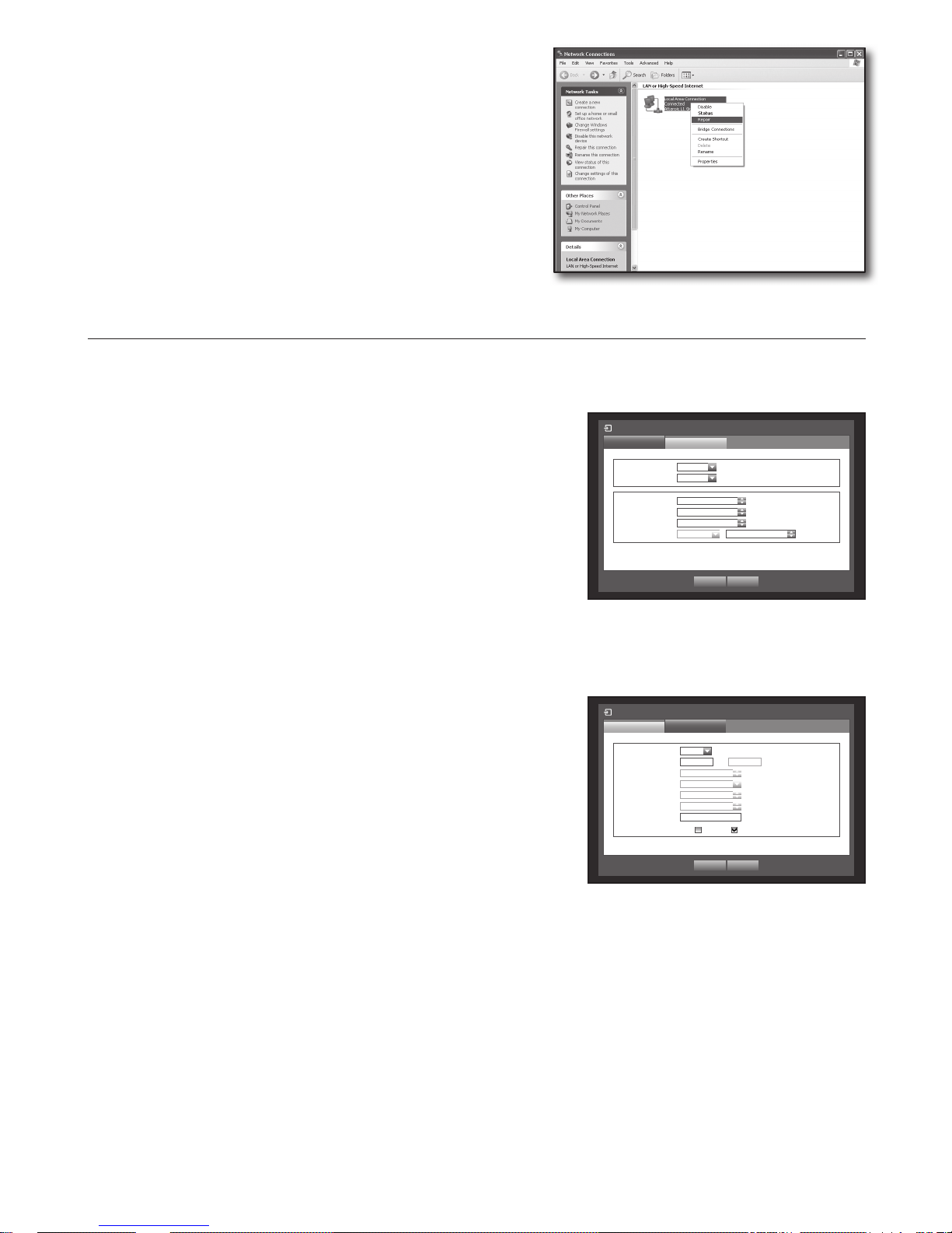
7. If the connection does not establish, check all cable connections
and go to step 2.1 and select <Repair>.
On the “Local Area Connection Status” window, click
<Support> tab and check <Default Gateway> if matches to the
one found in the [cmd.exe], and check the connection again.
Step 3. Connecting DVR to the router
Step 3.1 Configuring DVR router setup
1. Press the [MENU] button on the remote control.
2. Use the left/right button (◄►) to select <Network>.
Network menu is selected.
3. Use the up/down buttons (▲▼) to move to <Connection Mode>, and
press [ENTER] button.
4. Select <Interface>.
A window of connection mode setup appears.
5. Use direction buttons (▲▼◄►) to move to a desired item.
6. Enter the <IP address>.
The IP address consists of 4 fields, and the first 3 fields should be same to those of <Default Gateway> address of
your computer which can be found in Step 2, and the last field should be unoccupied number (between 2 and 254).
` ex) IP : 192.168.1.200
7. Enter the <Gateway> and <Subnet Mask> as same to those of your computer found in Step 2.
8. Set the <Device Port> and <HTTP Port>.
Set the Device Port and HTTP Port by referring to next page.
Connection Mode
Interface
Port
IP Type Static
Transfer Bandwidth 2Mbps
OK Cancel
IP Address 192.168.1.200
Gateway 192.168.1.1
Subnet Mask 255.255.255.0
DNS Manual 168.126.63.1
Connection Mode
Port
Interface
Protocol Type TCP
Device Port 4520 ~ 4524
UDP Port 8000 ~ 8160
Unicast/Multicast UDP-Unicast
Multicast IP Address 224.126.63.1
Multicast TTL 5
HTTP Port 80
Secure Video Transmission ON OFF
* Multi Browser Support:
Device Port 4505~4530, HTTP Port 80
OK Cancel
Page 5
English-5
What is port?
As usual, the <HTTP Port> uses port 80.
If the port is not setted, it is automatically regarded to 80 in http protocol.
For example, http://www.yahoo.com and http://www.yahoo.com:80 are regarded the same.
Hence, if the <HTTP Port> has been changed other than 80, you need to specify the address as: http://<IP
ADDRESS>:<HTTP Port>
` ex) http://192.168.1.200:80 to connect to the DVR using internet browser.
(Only when the port is set to 80, you can omit the port in the address.)
It is recommended to set <HTTP Port> to port number between 1024 and 65535.
If the port is not set to 80, accessing can be restricted depending on your service provider’s security policy or firewall
configuration.
DVR uses <HTTP Port> and <Device Port> for web connections.
<HTTP Port> is used for accessing DVR by using an internet browser.
<Device Port> is used for receiving video from DVR to internet browser.
J
` When configuring multiple DVR, <HTTP Port> and <Device Port> settings should be configured differently for each
device.
` ex) DVR #1 Device Port : 4520, HTTP Port : 80
DVR #2 Device Port : 50000, HTTP Port : 2000
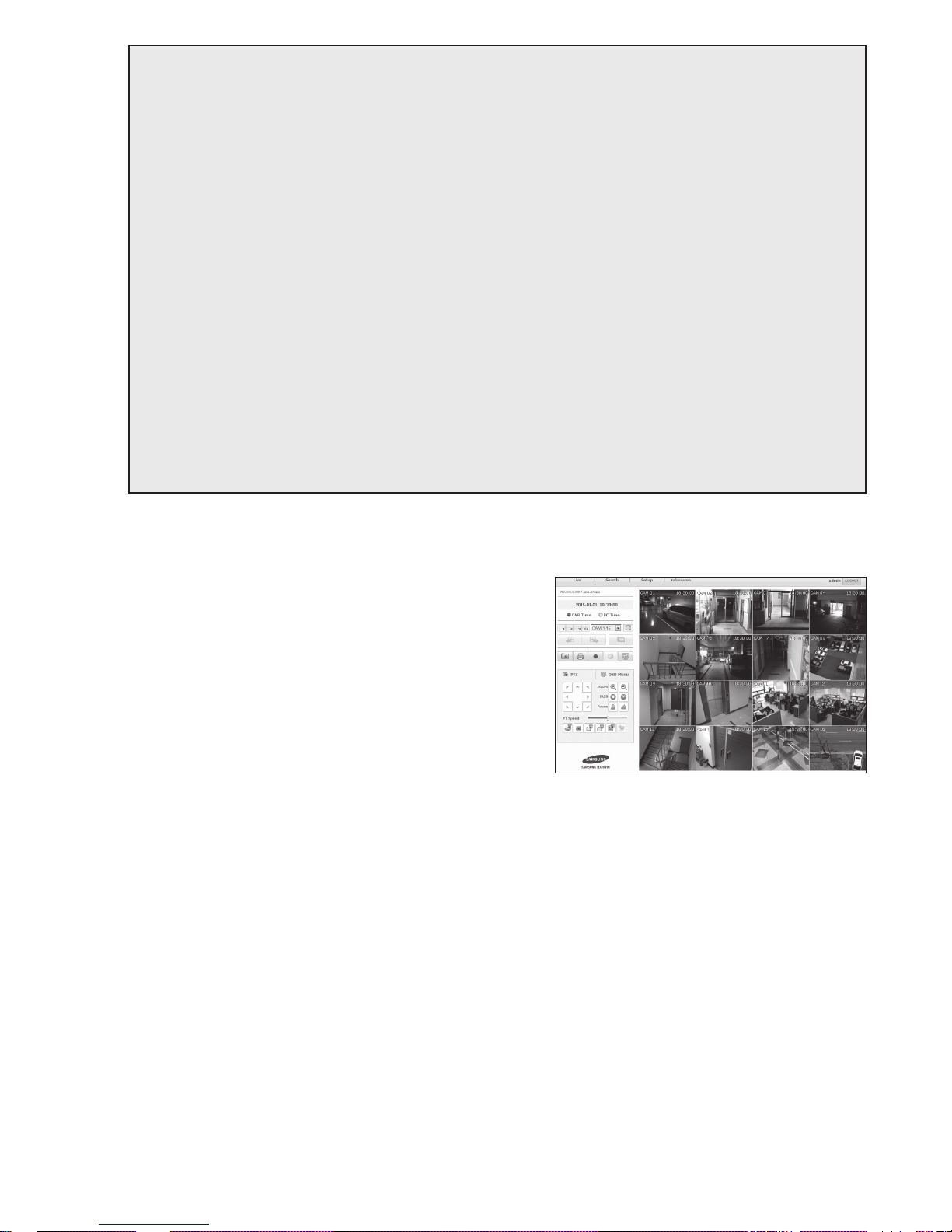
Step 3.2 Checking DVR connection on your computer
1. Run the Internet Explorer, and enter the <IP ADDRESS> and
<HTTP Port> of the DVR into the address, and press [Enter].
` ex) http://192.168.1.200:80
2. If the connection establishes properly, the Web Viewer screen
appears.
3. If the connection fails, check Steps 1, 2 and 3 to confirm the
connection setup.
Page 6
English-6
Step 4. Connecting the router to the internet service line
Internet connection setup method and steps may differ from routers, check your router’s setup method.
Connection types according to your internet service
Setting the internet connection may differ from internet service types, check your environment before proceeding and
select the appropriate connection type.
~ DHCP(Dynamic) : IP environment which allocates IP address automatically.
~ Static(Fixed) : IP environment using public IP addresses.
~ PPPoE: Common in DSL environments, which requires ADSL access ID and password.
Ask your internet service provider for the user ID and password.
` Name of each type described above may differ from router manufacturers.
Step 4.1 Connection guide by routers
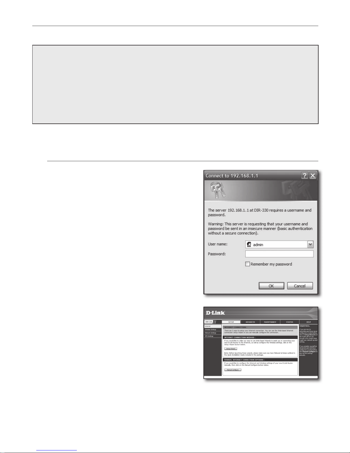
Step 4.1-Case 1. D-LINK DIR-330
1. Run the Internet Explorer and enter the <Default Gateway>
found in Step 2 into the address field and press [Enter].
2. When the router login screen appears, enter the <User name>
and <Password>.
Refer to the router user manual for ID and password.
3. Select internet connection method from connection setup wizard
and manual setup.
Selecting the Internet Connection Setup Wizard automatically
moves to the next step.
4. For manual setups, click <Manual Configure>.
Page 7
English-7
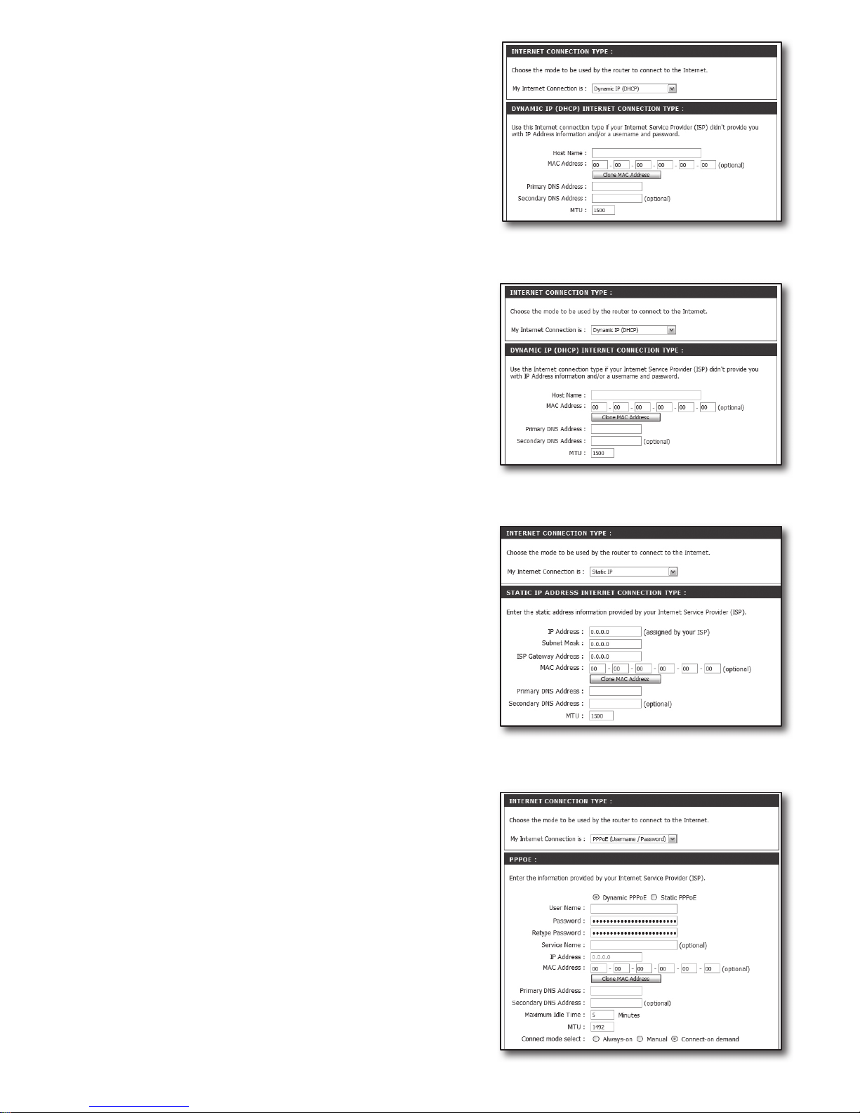
5. Select your <Internet Connection Type>.
Dynamic IP Address Environment
6. Select <Dynamic IP (DHCP)>.
7. Click [Save Settings] button.
Static IP Address Environment
6. Select <Static IP>.
7. Enter the <IP Address>, <Subnet Mask>, and <ISP Gateway
Address> assigned by your ISP.
8. Click [Save Settings] button.
ADSL Environment
6. Select <PPPoE (Username/Password)>.
7. Enter your <User Name> and <Password>.
Ask your internet service provider for the username and
password.
Page 8
English-8
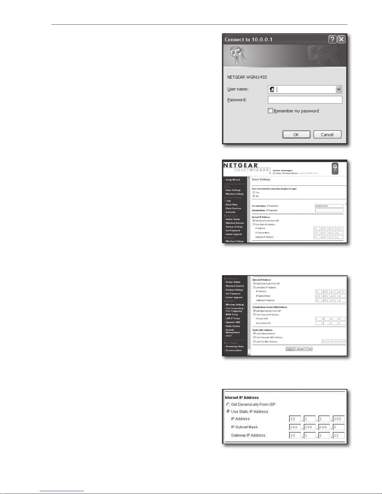
Step 4.1-Case 2. NETGEAR WGR614SS
1. Run the Internet Explorer and enter the <Default Gateway>
found in Step 2 into the address field and press [Enter].
2. Enter the user name and password when the router login window
appears.
Refer to the router user manual for user name and password.
3. Click <Setup>-<Basic Settings> on the left menu.
Click <Setup Wizard> for automatic setup.
Dynamic IP Address Environment
4. Select <Get Dynamically From ISP>.
5. Click [Apply] button.
Static IP Address Environment
4. Select <Use Static IP Address>.
5. Enter <IP Address>, <IP Subnet Mask> and <Gateway IP
Address>.
6. Click [Apply] button.
Page 9
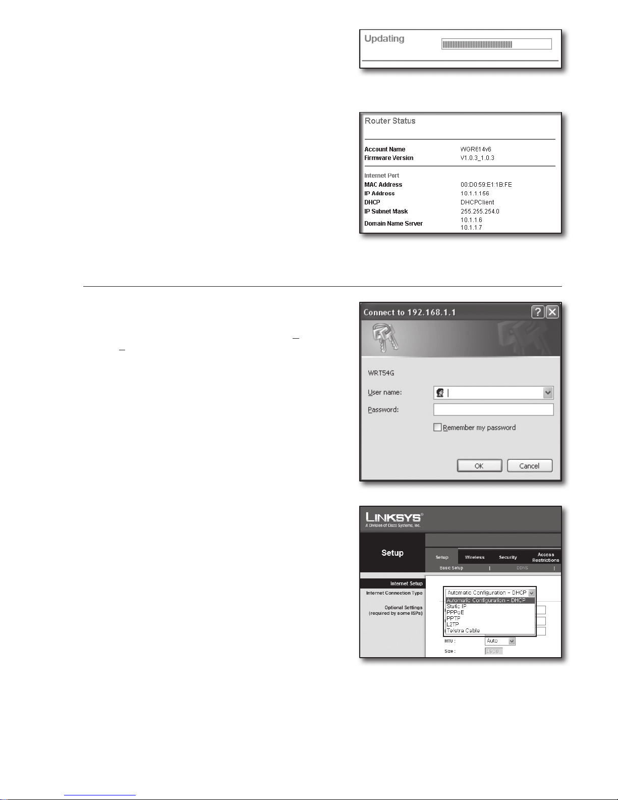
English-9
7. It saves the changes.
To check the connection
Once connected, status indicator <DHCPClient> is displayed on
the top side of the settings screen.
Step 4.1-Case 3. LINKSYS WRT54G
1. Run the Internet Explorer and enter the <Default Gateway>
found in Step 2 into the address field and press [Enter].
2. When the router login screen appears, enter the <User name>
and <Password>.
Refer to the router user manual for ID and password.
3. Click <Internet Setup>.
4. Select your <Internet Connection Type>.
According to your selection of connection type, different settings
screen will appear.
Page 10
English-10
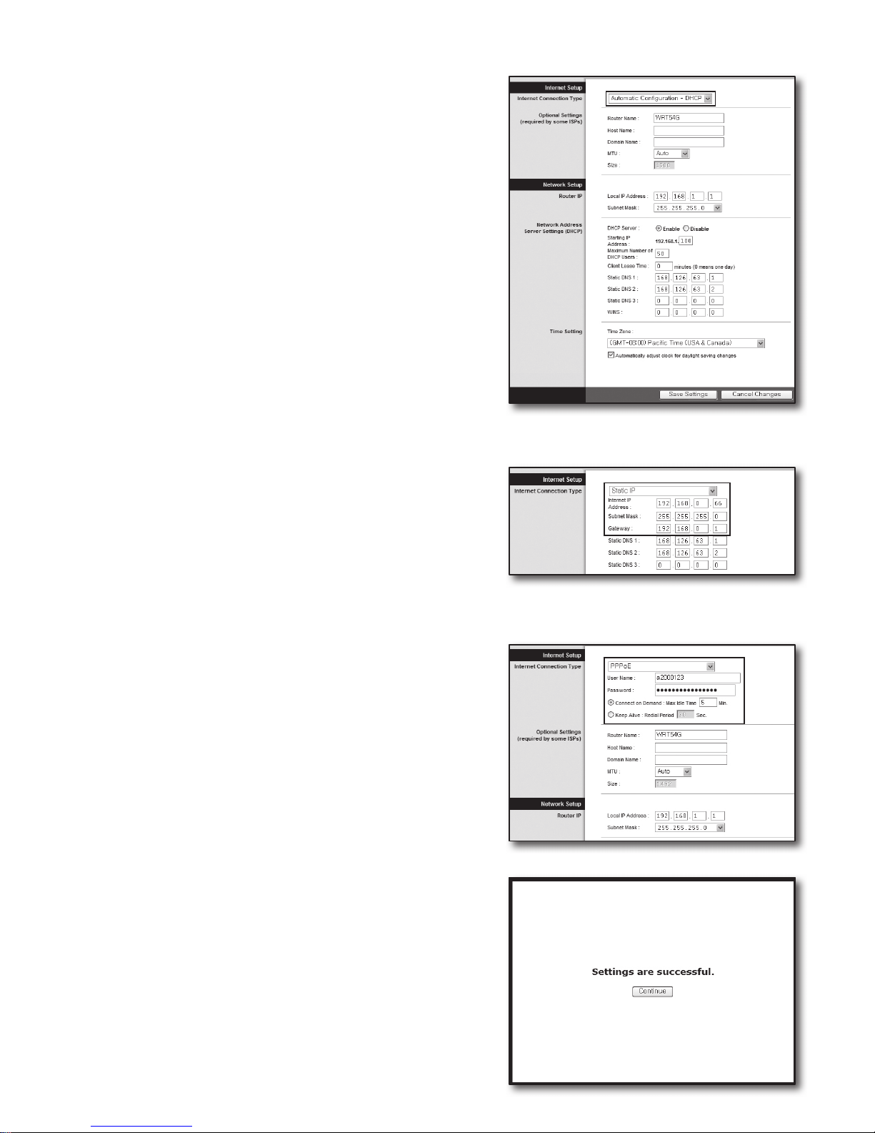
Dynamic IP Address Environment
5. Select <Automatic Configuration – DHCP>.
6. Click [Save Settings] button on the bottom.
Static IP Address Environment
5. Select <Static IP>.
6. Enter <Internet IP Address>, <Subnet Mask>, and
<Gateway> assigned by your ISP.
7. Click [Save Settings] button on the bottom.
ADSL Environment
5. Select <PPPoE>.
6. Enter your <User Name> and <Password>.
Ask your internet service provider for the username and
password.
7. Click [Save Settings] button on the bottom.
8. Once finished, completion screen appears.
Page 11
English-11
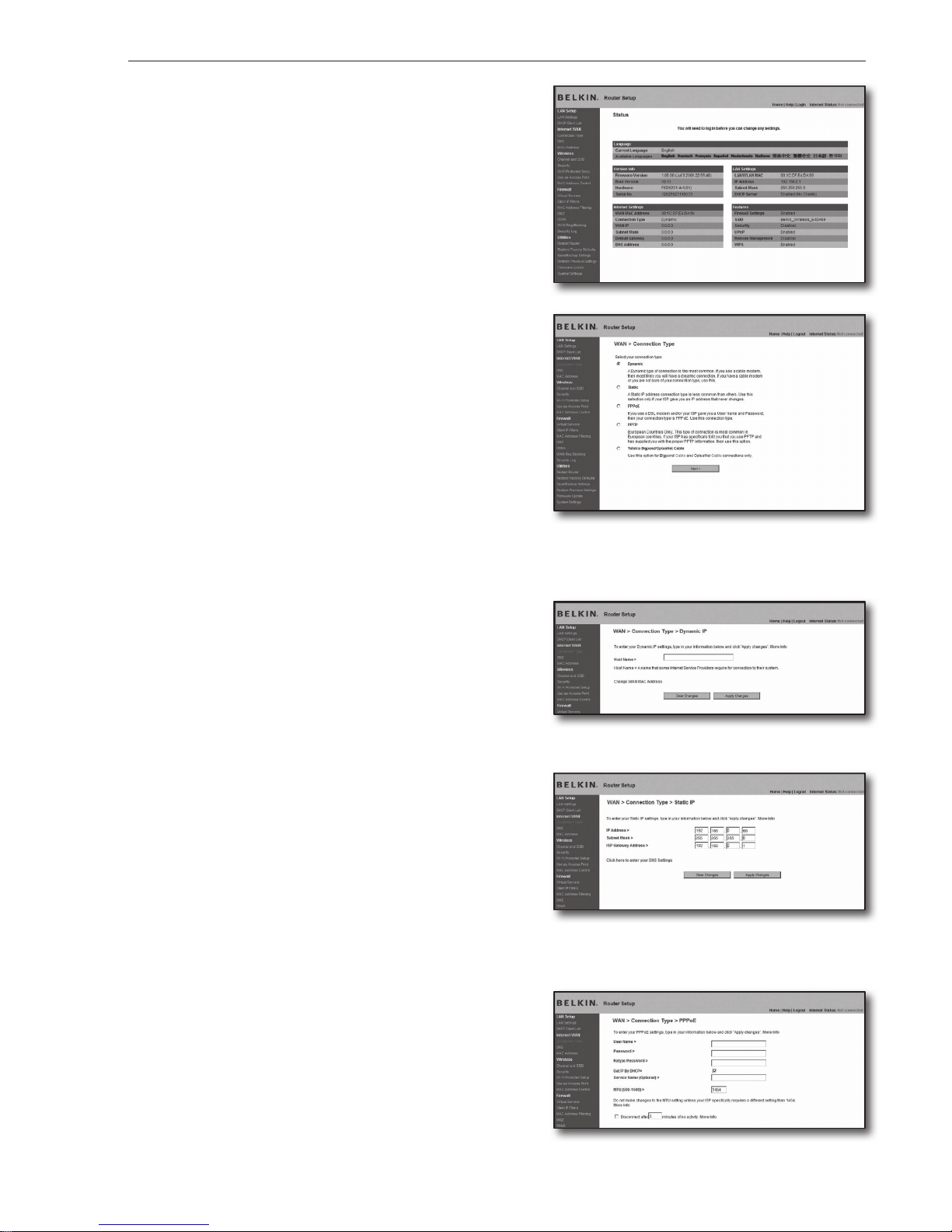
Step 4.1-Case 4. BELKIN F5D8236-4
1. Run the Internet Explorer and enter the <Default Gateway>
found in Step 2 into the address field and press [Enter].
2. Click <WAN>-<Connection Type>.
Select your internet service type.
Dynamic IP Address Environment
3. Select <Dynamic> for the connection type and click [Next>]
button.
4. Enter the <Host Name> and click [Apply Changes] button.
` If your ISP provided specific DNS addresses, click <WAN>-<DNS>
and enter the provided DNS addresses.
Static IP Address Environment
3. Select <Static> for the connection type and click [Next>] button.
4. Enter the <IP Address> assigned by your ISP.
5. Enter <Subnet Mask> and <ISP Gateway Address>.
6. Click [Apply Changes] button.
ADSL Environment
3. Select <PPPoE> for the connection type and click [Next>]
button.
4. Enter user name and password.
Ask your internet service provider for the user name and
password.
5. Click [Apply Changes] button.
Page 12
English-12
To check the connection
Once connected, status indicator <Connection> is displayed on the
top side of the settings screen.
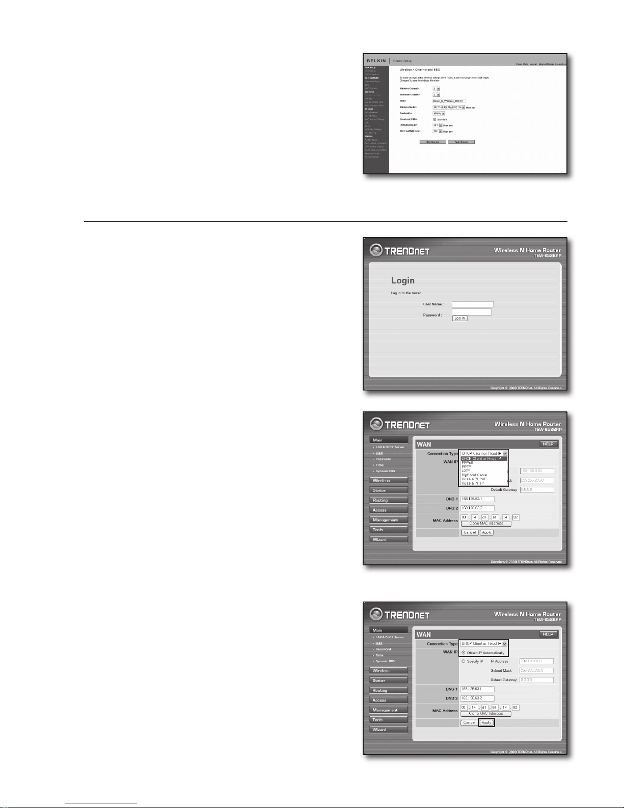
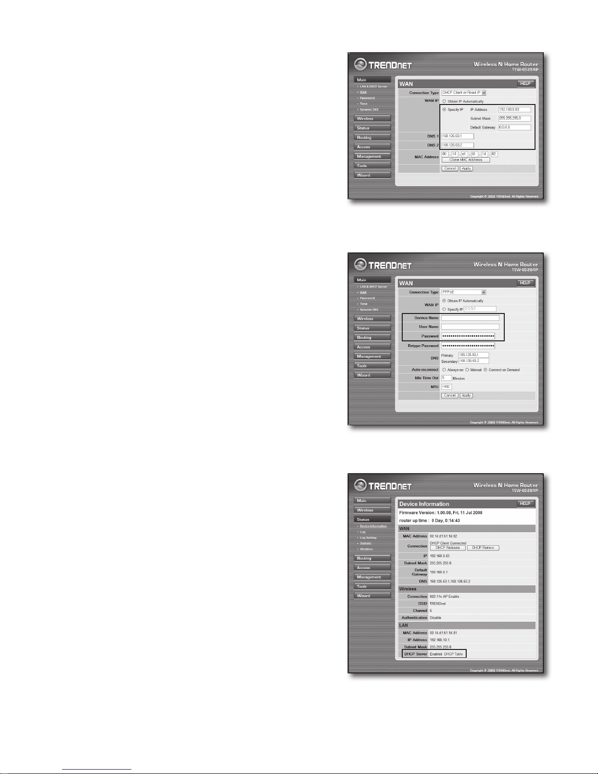
Step 4.1-Case 5. TRENDNET TEW-652BRP
1. Run the Internet Explorer and enter the <Default Gateway>
found in Step 2 into the address field and press [Enter].
2. Enter the user name and password when the router login window
appears.
Refer to the router user manual for ID and password.
3. Click <WAN> on the left menu of he settings screen.
4. Select your <Connection Type>.
Dynamic IP Address Environment
5. Select <DHCP Client or Fixed IP>.
6. Click <Obtain IP Automatically>.
` If your ISP provided specific DNS addresses, click <WAN>-<DNS>
and enter the provided DNS addresses.
7. Click [Apply] button on the bottom.
Page 13
English-13
Static IP Address Environment
5. Select <DHCP Client or Fixed IP>.
6. Select <Specify IP>.
7. Enter the <IP Address>, <Subnet Mask>, and <Default
Gateway>.
8. Enter <DNS1> and <DNS2>.
` If your ISP provided specific DNS addresses, click <WAN>-<DNS>
and enter the provided DNS addresses.
9. When finished, click [Apply] button on the bottom.
ADSL Environment
5. Select <PPPoE>.
6. Select appropriate method of obtaining <WAN IP> address.
7. Enter the <Service Name>, <User Name> and <Password>.
Ask your internet service provider for the user name and
password.
To check the connection
8. Click <Status>-<Device Information> on the left menu, and
check the server’s current status at <DHCP Server> under the
LAN category.
When the connection establishes successfully, it displays
<Enabled DHCP Table>.
Page 14
English-14
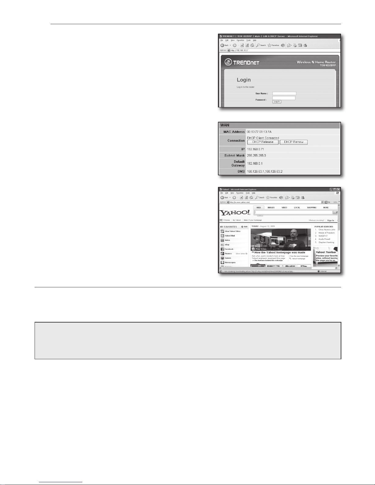
Step 4.2 Checking the connection to the internet
1. Run the Internet Explorer on your computer.
2. Enter the <Default Gateway> found in the Step 2 into the
address field and press [Enter].
3. Click Status tab on the router menu.
4. Check the WAN (Internet) connection status and WAN (Internet)
IP address.
5. When the connection establishes successfully, it displays
<DHCP Client Connected> message and the WAN (Internet) IP
shows an address.
6. Using the Internet Explorer, access Yahoo, Google and other well
known web servers.
7. If the connection is properly set, Internet Explorer displays visiting
web server’s page correctly.
8. If connection fails, go to Step 4 and check again.
Step 5. Port forwarding
Port forwarding should be configured for accessing from the outside of the router network to a computer or DVR is connected
to the router.
Configure your router’s port forwarding as followings.
What is port forwarding?
It is a port mapping function of <Router’s WAN (Internet) IP: Port> to <DVR’s IP: Port>, that helps opening a
communication channel between inside and outside of the private LAN
Since one DVR uses 2 ports for communication, port forwarding setup for both 2 ports should be configured.
J
` If only <HTTP Port> is configured for port forwarding:
Accessing through the web browser is possible but video is not received since the <Device Port> for video data communication is
not configured for port forwarding.
If only <Device Port> is configured for port forwarding:
Accessing through the web browser is impossible since the <HTTP Port> for the communication is not configured for port
forwarding.
In the below, port forwarding methods for each router are explained.
For other routers not guided herein, refer to the user manual of the router.
Page 15
English-15
Step 5.1 Port forwarding guide by routers
Run the Internet Explorer and enter the <Default Gateway> of the computer, which is the router’s IP address found in
Step 2, into the address field and pres [Enter].
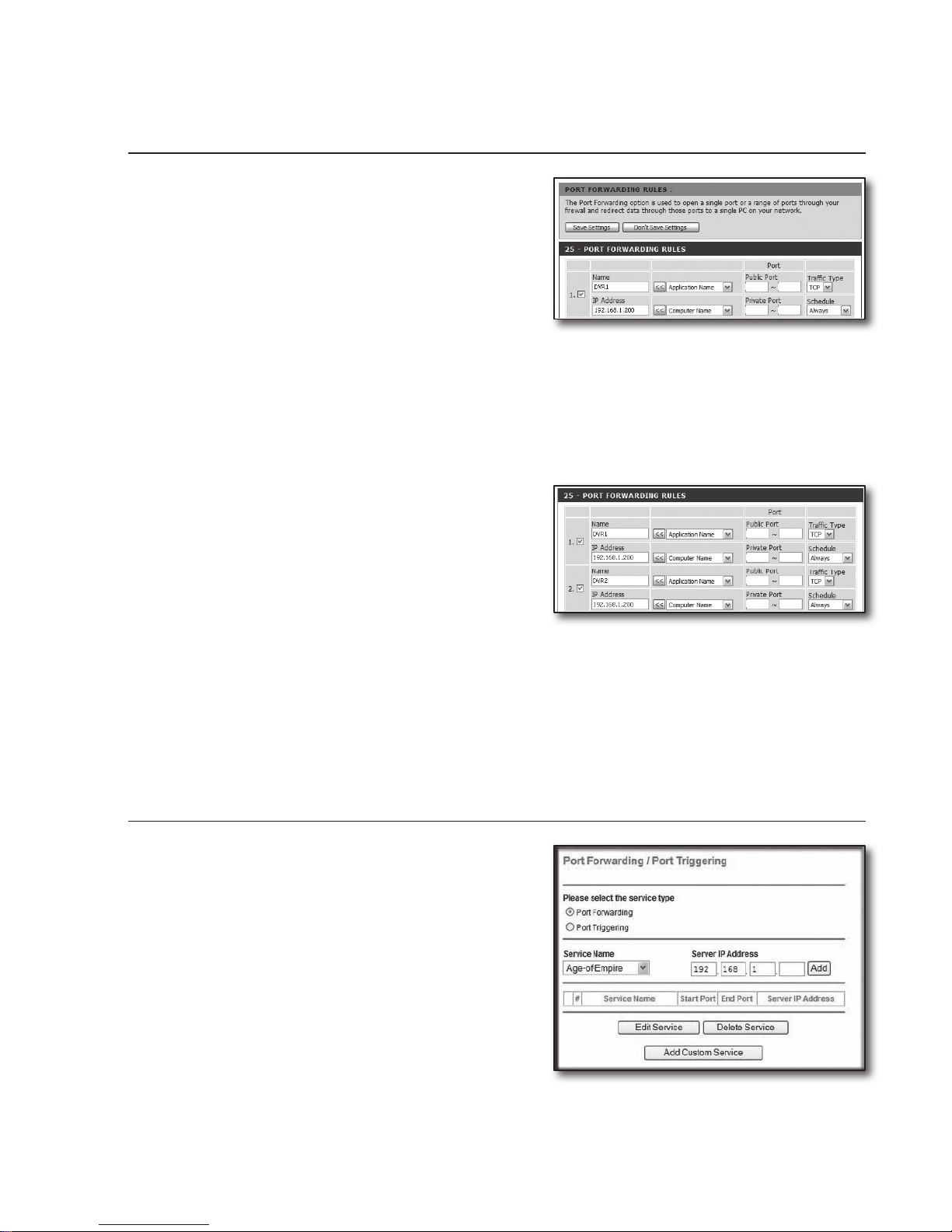
Step 5.1-Case 1. D-LINK DIR-330
1. Select <Advanced>.
2. Set the <HTTP Port> for port forwarding.
2
-1
. Check the <Checkbox> to select it.
2
-2
. Enter a name for the DVR port in the <Name> field.
` ex) DVR1
2-3. In the <Public Port>, enter the <HTTP Port> defined in
Step 3.
` ex) 80~80
2-4. In the <Private Port>, enter the <HTTP Port> defined in Step 3.
` ex) 80~80
2-5. In the <IP Address>, enter the DVR's IP address defined in Step 3.
` ex) 192.168.1.200
2-6. For the <Traffic Type>, select <Any>.
3. Set the <Device Port> for port forwarding.
3
-1
. Check the <Checkbox> to select it.
3
-2
. Enter a name for the DVR port in the <Name> field.
` ex) DVR2
3-3.
In the <Public Port>, enter the <
Device Port
> defined in
Step 3.
` ex) 4520~4524
3-4. In the <Private Port>, enter the <Device Port> defined in Step 3.
` ex) 4520~4524
3-5. In the <IP Address>, enter the DVR's IP address defined in Step 3.
` ex) 192.168.1.200
4. After completion, click [Save Settings] button.
Step 5.1-Case 2. NETGEAR 614SS
1. Click <Port Forwarding / Port Triggering> in the left menu.
2. Select <Port Forwarding>.
3. Set the <HTTP Port> for port forwarding.
3
-1
. Set the <Add Custom Service> for port forwarding.
8080
8080
80 80
80 80
4520 4524
4520 4524
Page 16
English-16
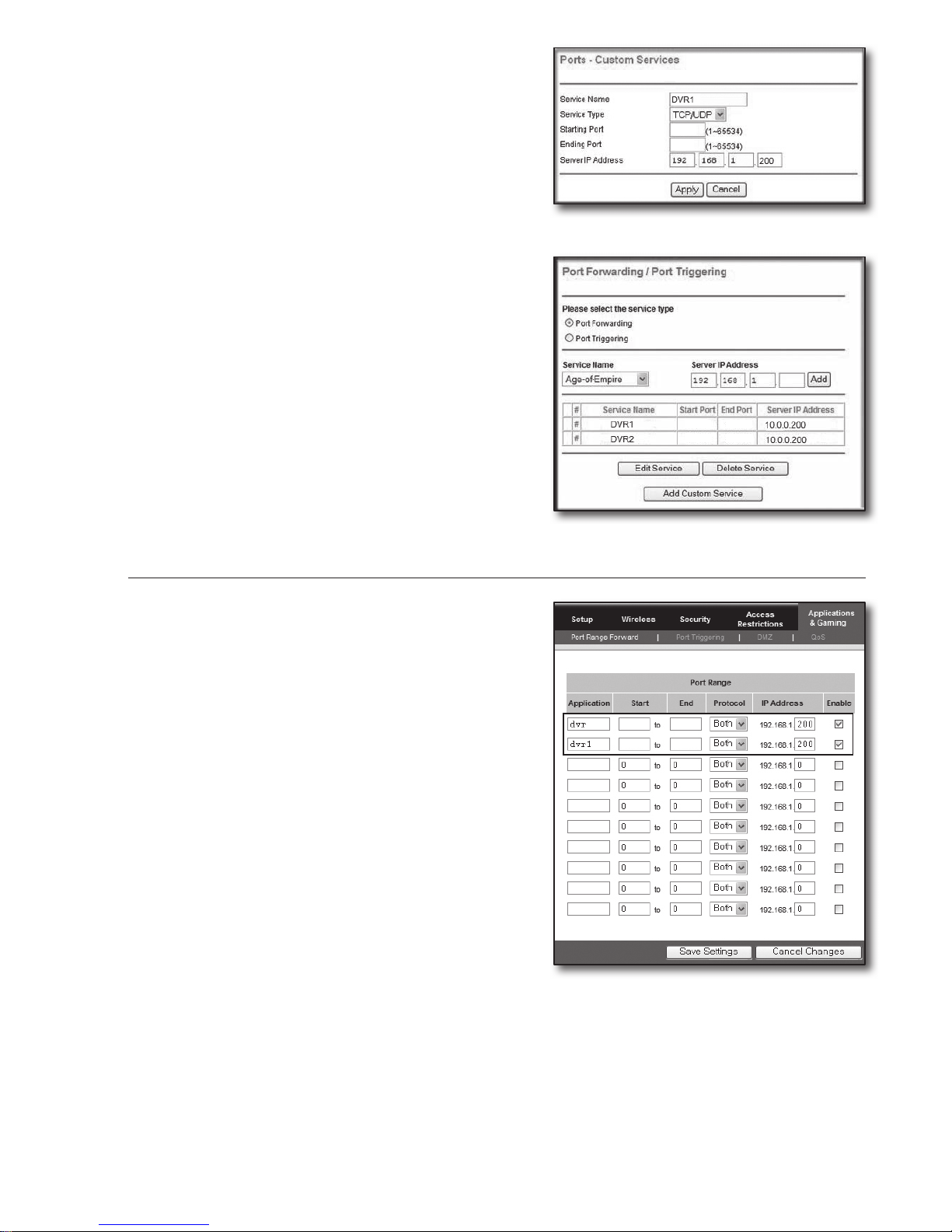
3-2.
Enter a name for the DVR port in the <Service Name> field.
` ex) DVR1
3-3. Enter the <Starting Port> and <Ending Port> while
matching to that of <HTTP Port> defined in Step 3.
` ex) 80
3-4. In the <Server IP Address>, enter the DVR's IP address
defined in Step 3.
` ex) 192.168.1.200
3-5. Click [Apply] button to finish the setting.
4. Set the <Device Port> for port forwarding.
4
-1
. Click <Add Custom Service> button.
4
-2
. Enter a name for the DVR’s <Device Port> in the
<Service Name> field.
` ex) DVR2
4-3. Enter the <Start Port> and <End Port> while matching to
that of <Device Port> defined in Step 3.
` ex) 4520,4521,4522,4523,4524
4-4. In the <Server IP Address>, enter the DVR's IP address
defined in Step 3.
` ex) 192.168.1.200
4-5. Click [Apply] button to finish the setting.
Step 5.1-Case 3. LINKSYS WRT54G
1. Click <Applications & Gaming>.
2. Set the <HTTP Port> for port forwarding.
2
-1
. Enter a name for the DVR port in the <Application> field.
` ex) DVR1
2-2. In the <Start> and <End> fields, enter the <HTTP Port>
defined in Step 3.
` ex) 80
2-3. Select [Both] for the <Protocol>.
2
-4
. In the <IP Address>, enter the DVR's IP address defined in
Step 3.
` ex) 192.168.1.200
2-5. Check the checkbox of <Enable> column for the specified
port.
3. Set the <Device Port> for port forwarding.
3
-1
. Enter a name for the DVR port in the <Application> field.
` ex) DVR2
3-2.
In the <Start> and <End> fields, enter the <
Device Port
>
defined in Step 3.
3-3. Select [Both] for the <Protocol>.
3
-4
. In the <IP Address>, enter the DVR's IP address defined in Step 3.
` ex) 192.168.1.200
3-5. Check the checkbox of <Enable> column for the specified port.
80
80
80
4520804524
80
4524
80
4520
Page 17
English-17
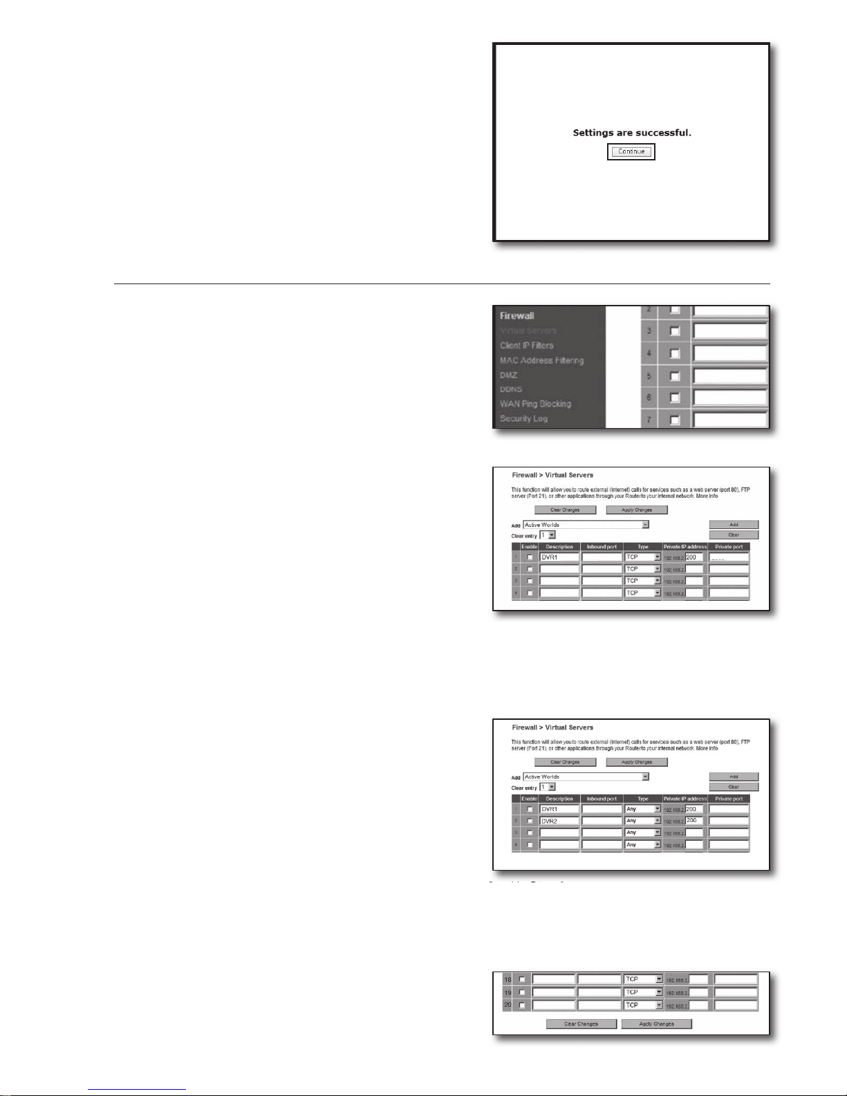
4. Click [Save Settings] button on the bottom.
5. Once finished, completion screen appears.
Step 5.1-Case 4. BELKIN F5D8236-4
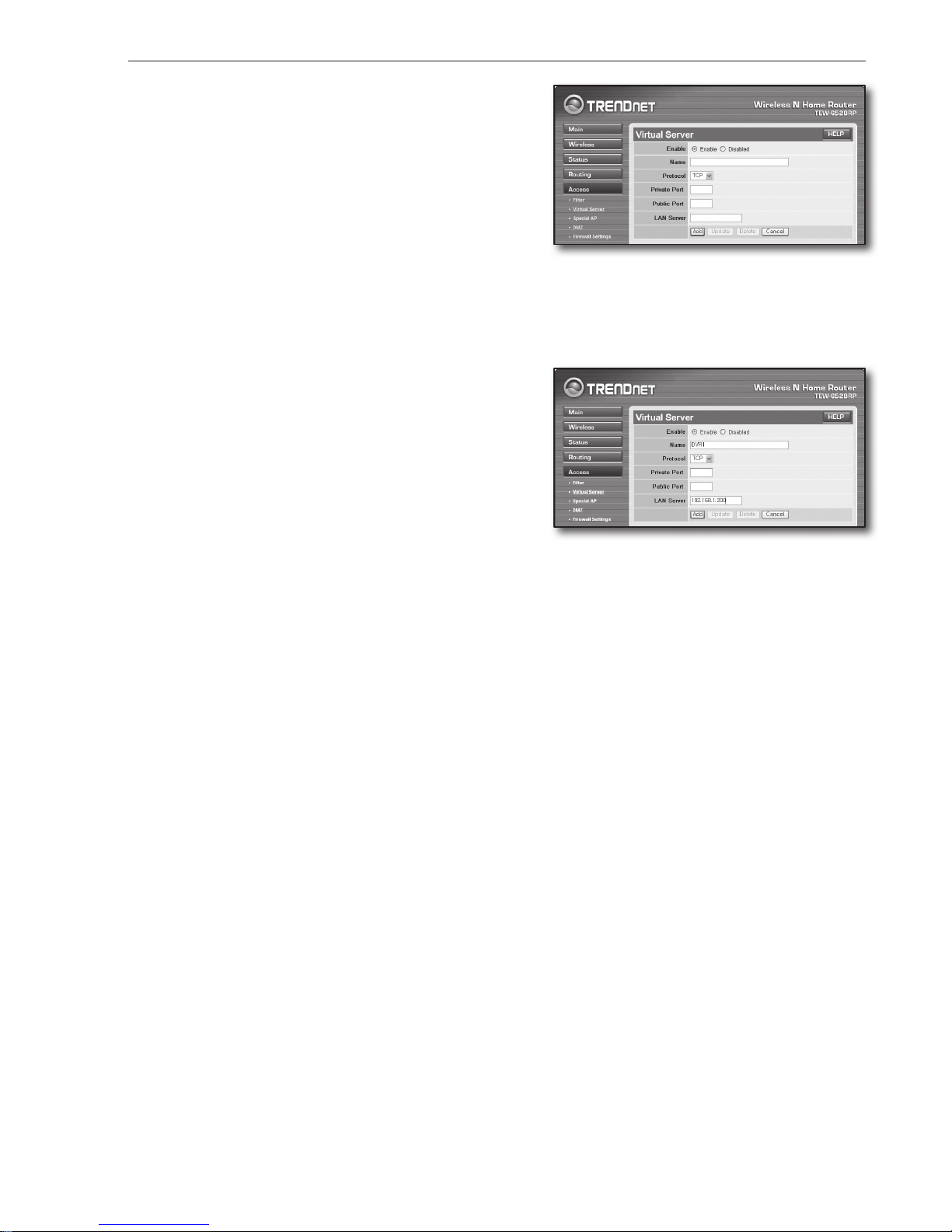
1. Click <Firewall>-<Virtual Servers> on the left menu.
2. Set the <HTTP Port> for port forwarding.
2
-1
. Check the <Enable> checkbox to mark selected.
2
-2
. Enter a name for the DVR port in the <Description> field.
` ex) DVR1
2-3. In the <Inbound port>, enter the <HTTP Port> defined in
Step 3.
` ex) 80
2-4. For the <Type>, select [Any].
2
-5
. In the <Private IP address>, enter the DVR's IP address defined in Step 3.
` ex) 192.168.1.200
2-6. In the <Private port> field, enter the <HTTP Port> defined in Step 3.
` ex) 80
3. Set the <Device Port> for port forwarding.
3
-1
. Check the <Enable> checkbox to mark selected.
3
-2
. Enter a name for the DVR port in the <Description> field.
` ex) DVR2
3-3. In the <Inbound port> fields, enter the <Device Port>
defined in Step 3.
` ex) 4520,4521,4522,4523,4524
3-4. For the <Type>, select [Any].
3
-5
. In the <Private IP address>, enter the DVR's IP address defined in Step 3.
` ex) 192.168.1.200
3-6. In the <Private port> fields, enter the <Device Port> defined in Step 3.
` ex) 4520,4521,4522,4523,4524
4. Once finished, click [Apply Changes] button.
80 80
80
4524
80
4524
Page 18
English-18
Step 5.1-Case 5. TRENDNET TEW-652BRP
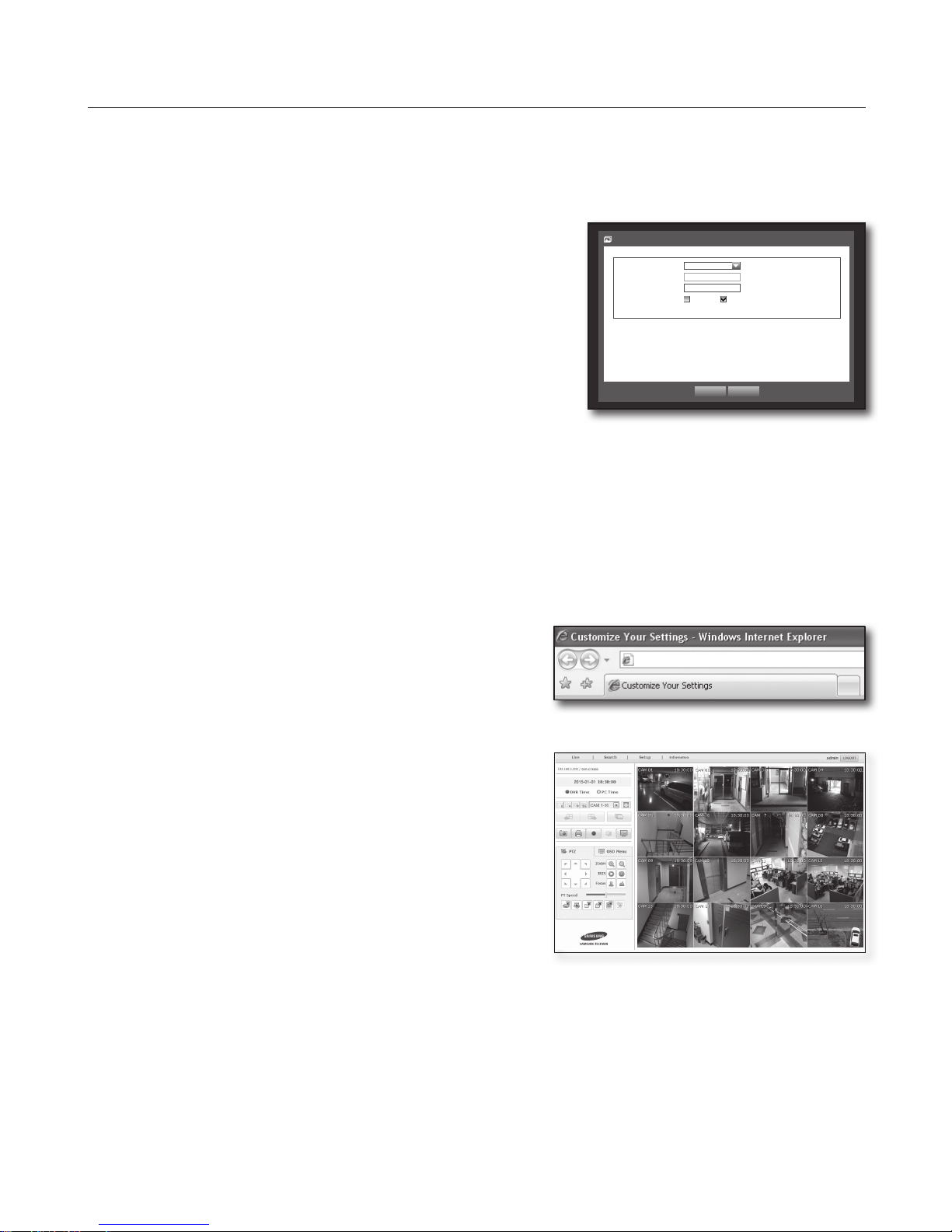
1. Click <Access>-<Virtual Server> on the left menu.
2. Set the <HTTP Port> for port forwarding.
2
-1
. Select [Enable] for the item <Enable>.
2
-2
. Enter a name for the DVR port in the <Name> field.
` ex) DVR1
2-3. Select [TCP] for the item <Protocol>.
2
-4
. In the <Private Port> and <Public Port> fields, enter the
<HTTP Port> defined in Step 3.
` ex) 80
2-5. In the <LAN Server>, enter the DVR's IP address defined in Step 3.
` ex) 192.168.1.200
2-6. Click [ADD] button.
3. Set the <Device Port> for port forwarding.
3
-1
. Select [Enable] for the item <Enable>.
3
-2
. Enter a name for the DVR port in the <Name> field.
` ex) DVR2
3-3. Select [TCP] for the item <Protocol>.
3
-4
. In the <Private Port> and <Public Port> fields, enter the
<Device Port> defined in Step 3.
` ex) 4520,4521,4522,4523,4524
3-5. In the <LAN Server>, enter the DVR's IP address defined in Step 3.
` ex) 192.168.1.200
3-6. Click [ADD] button.
4. Settings completed.
Step 5.2 Checking port forwarding on your computer
1. Confirm the router’s <WAN (Internet) IP> which has been checked in Step 4.2 again.
2. Confirm the DVR’s <HTTP Port> checked in Step 3.1 again.
3. Run the Internet Explorer and enter http://<WAN (Internet) IP>:<HTTP Port> into the address field and press [Enter].
4. DVR's Web Viewer screen appears if port forwarding configuration has been properly set.
5. If you cannot access to the Web Viewer or accessed but no video is displayed, go to the Step 5.1 and check again.
J
` If only <HTTP Port> is configured for port forwarding:
Accessing through the web browser is possible but video is not received since the <Device Port> for video data
communication is not configured for port forwarding.
If only <Device Port> is configured for port forwarding:
Accessing through the web browser is impossible since the <HTTP Port> for the communication is not configured for port
forwarding.
4524
4524
80
80
Page 19
English-19
Step 6. Accessing DVR using DDNS service in dynamic IP
environment
Since the router’s WAN IP address may vary in xDSL/Cable connections hiring dynamic IP allocations, DDNS (Dynamic Domain
Name Server) service is provided for accessing the DVR with fixed DDNS address in dynamic IP network environments.
Step 6.1 DVR DDNS configuration
1. Use the up/down buttons (▲▼) in <Network> window to move to
<DDNS>, and press [ENTER] button.
2. Use virtual keyboard to enter user inputs.
` Refer to “Using Virtual Keyboard”.
~ If selected <OFF> or <iPOLiS>, input fields are deactivated.
~ If you select <iPOLiS>, the “DDNS Host Address” item will be
displayed.
- Type your set ID in <Product ID> field.
More specific information is in “iPOLiS DDNS Setting”.
- Select <Use> in <Quick Connect> menu. After finishing
“iPOLiS
DDNS Setting”, you can connect your DVR set with the address <http://www.samsungipolis.com/
SDRC75300HOMEDVR>.
` The router used should support uPNP Port Forwarding function.
` Note that uPNP Port Forwarding does not support UDP protocol.
` If the program fails to read uPNP Port Forwarding List, try again after restarting the computer and router.
3. When the DDNS setup is done, press <OK>.
Step 6.2 Accessing DVR using DDNS address
1. Run the Internet Explorer and enter the DDNS address found in
Step 6.1 into the address field end press [Enter].
2. DVR’s Web Viewer screen appears.
3. If failed with accessing, go to the Step 6.1 and check the settings
again.
M
` It may take up to 10 minutes for updating the router’s IP
address recorded in the DDNS server. When failed with
accessing, retry after 10 minutes.
DVR reports its IP address to the DDNS server at every 10
minutes.
Configuration completed.
By remembering the DDNS address, ID and password, you can connect to your DVR from any computer that is
connected to the internet.
For further operating information, refer to the user manual.
http://www.samsungipolis.com/SDRC75300HOMEDVR
OK Cancel
DDNS
DDNS Site iPOLiS
Server Name www.samsungip...
Product ID
SDRC75300HOMEDVR
Quick Connect Not Use Use
DDNS Host Address http://www.samsungipolis.com/SDRC75300HOMEDVR
 Loading...