

Samsung SDE-120N, SDE-3000N, SDE-3001N, SDE-3170P, SDE-3002 User Manual
...
4 CHANNEL DVR
User Manual
SDE-120N/SDE-3000N/SDE-3001N
SDE-3170P/SDE-3002/SDE-3002P
Lo-Call 1890 866 900
www.cctvireland.ie

2_ overview
FEATURES
This product enables you to record 4 channels of camera image and voice source simultaneously. This feature
provides an excellent picture quality for both real time monitoring and search.
You can also monitor remote videos or search for your previous recordings and change the menu settings of the
DVR via the network.
As this product can bypass the Windows operating system to implement the DVR-specific operating system on its
hardware components, the overall operation is stable.
This product compresses the 4 channels of camera input into a format of H.264 before converting analog to
digital video, which enables you to make an effective use of your hard disk.
You can use the remote control, mouse, search buttons on the front panel or a combination of them to perform
freeze, fast playback, backward playback as well as monitoring an event of detection such as time, motion and
alarm.
It provides various recording modes including continuous, motion and alarm recordings.
Supports DDNS (use dynamic IP as like static IP)
USB Back Up
Separate resolution settings for each channel
Separate motion area settings for each channel
Supports a triplex tasking of Save and Remote View during a search.
Motion Detection Recording
Prevents unauthorized user control and data loss using the password system
Supports operations of the remote control and mouse
Ordinary DIY or BNC camera are supported
NTSC : Up to 120 frames(Based on 352 x 240)
PAL : Up to 100 frames(Based on 352 x 288)
Record and play in high quality
NTSC : Based on 704 x 480
PAL : Based on 704 x 576
High/low speed search (search list/speed search)
Continuous recording in HDD Overwrite mode
•
•
•
•
•
•
•
•
•
•
•
•
•
•
•
•
-
-
•
•
overview
Lo-Call 1890 866 900
www.cctvireland.ie

English _3
OVERVIEW
IMPORTANT SAFETY INSTRUCTIONS
Read these operating instructions carefully before using the unit.
Follow all the safety instructions listed below.
Keep these operating instructions handy for future reference.
Read these instructions.
Keep these instructions.
Heed all warnings.
Follow all instructions.
Do not use this apparatus near water.
Clean only with dry cloth.
Do not block any ventilation openings, Install in accordance with the manufacturer’s instructions.
Do not install near any heat sources such as radiators, heat registers, stoves, or other apparatus
(including amplifiers) that produce heat.
Do not defeat the safety purpose of the polarized or grounding- type plug. A polarized plug has two
blades with one wider than the other. A grounding type plug has two blades and a third grounding
prong. The wide blade or the third prong are provided for your safety. if the provided plug does not fit
into your outlet, consult an electrician for replacement of the obsolete outlet.
Protect the power cord from being walked on or pinched particularly at plugs, convenience
receptacles, and the point where they exit from the apparatus.
Only use attachments/accessories specified by the manufacturer.
Use only with the cart, stand, tripod, bracket, or table specified by the
manufacturer, or sold with the apparatus. When a cart is used, use caution
when moving the cart/apparatus combination to avoid injury from tip-over.
Unplug this apparatus during lightning storms or when unused for long periods
of time.
Refer all servicing to qualified service personnel. Servicing is required when the apparatus has been
damaged in any way, such as power-supply cord or plug is damaged, liquid has been spilled or
objects have fallen into the apparatus, the apparatus has been exposed to rain or moisture, does not
operate normally, or has been dropped.
1)
2)
3)
4)
5)
6)
7)
8)
9)
10)
11)
12)
13)
14)
Lo-Call 1890 866 900
www.cctvireland.ie

4_ overview
overview
CAUTION
RISK OF ELECTRIC SHOCK.
DO NOT OPEN
CAUTION
: TO REDUCE THE RISK OF ELECTRIC SHOCK, DO NOT REMOVE COVER (OR BACK) NO USER
SERVICEABLE PARTS INSIDE. REFER SERVICING TO QUALIFIED SERVICE PERSONNEL.
This symbol indicates that dangerous voltage consisting a risk of electric shock is present within
this unit.
This exclamation point symbol is intended to alert the user to the presence of important operating
and maintenance (servicing) instructions in the literature accompanying the appliance.
WARNING
To reduce the risk of fire or electric shock, do not expose this appliance to rain or moisture.
To prevent injury, this apparatus must be securely attached to the floor/wall in accordance with the installation
instructions.
WARNING
Be sure to use only the standard adapter that is specified in the specification sheet.
Using any other adapter could cause fire, electrical shock, or damage to the product.
Incorrectly connecting the power supply or replacing battery may cause explosion, fire, electric shock, or
damage to the product.
Do not connect multiple cameras to a single adapter. Exceeding the capacity may cause abnormal heat
generation or fire.
Securely plug the power cord into the power receptacle. Insecure connection may cause fire.
When installing the camera, fasten it securely and firmly. The fall of camera may cause personal injury.
Do not place conductive objects (e.g. screwdrivers, coins, metal parts, etc.) or containers filled with water on
top of the camera. Doing so may cause personal injury due to fire, electric shock, or falling objects.
Do not install the unit in humid, dusty, or sooty locations. Doing so may cause fire or electric shock.
If any unusual smells or smoke come from the unit, stop using the product. In such case, immediately
disconnect the power source and contact the service center. Continued use in such a condition may cause fire
or electric shock.
If this product fails to operate normally, contact the nearest service center. Never disassemble or modify this
product in any way. (SAMSUNG is not liable for problems caused by unauthorized modifications or attempted
repair.)
When cleaning, do not spray water directly onto parts of the product. Doing so may cause fire or electric shock.
Do not expose the product to the direct airflow from an air conditioner.
Otherwise, it may cause moisture condensation inside the Clear Dome due to temperature difference between
internal and external of the dome camera.
If you install this product in a low-temp area such as inside a cold store, you must seal up the wiring pipe with
silicon, so that the external air can not flow inside the housing.
Otherwise, external high, humid air may flow inside the housing, pooling moisture or vapor inside the product
due to a difference between internal and external temperature.
•
•
1.
2.
3.
4.
5.
6.
7.
8.
9.
10.
11.
12.
Lo-Call 1890 866 900
www.cctvireland.ie

English _5
OVERVIEW
CAUTION
Do not drop objects on the product or apply strong blows to it. Keep away from a location subject to excessive
vibration or magnetic interference.
Do not install in a location subject to high temperature (over 50°C), low temperature (below -10°F), or high
humidity. Doing so may cause fire or electric shock.
If you want to relocate the already installed product, be sure to turn off the power and then move or reinstall it.
Remove the power plug from the outlet when there is a lighting storm. Neglecting to do so may cause fire or
damage to the product.
Keep out of direct sunlight and heat radiation sources. It may cause fire.
Install it in a place with good ventilation.
Avoid aiming the camera directly towards extremely bright objects such as sun, as this may damage the CCD
image sensor.
Apparatus shall not be exposed to dripping or splashing and no objects filled with liquids, such as vases, shall
be placed on the apparatus.
The Mains plug is used as a disconnect device and shall stay readily operable at any time.
When using the camera outdoors, moisture may occur inside the camera due to temperature difference
between indoors and outdoors. For this reason, it is recommended to install the camera indoors. For outdoor
use, use the camera with built-in fan and heater.
CAUTION
Risk of explosion if battery is replaced by an incorrect type.
Dispose of used batteries according to the instructions.
LAN Ethernet cable should not be extended to outside of building.
1.
2.
3.
4.
5.
6.
7.
8.
9.
10.
1.
2.
Lo-Call 1890 866 900
www.cctvireland.ie

6_ overview
overview
BEFORE START
This user’s manual provides Information for using DVR such as brief introduction, part names, functions, connection
to other equipment, menu setup, and the like.
You have to keep in mind the following notices:
SAMSUNG retains the copyright on this manual.
This manual cannot be copied without SAMSUNG’s prior written approval.
We are not liable for any or all losses to the product incurred by your use of non-standard product or violation of
instructions mentioned in this manual.
If you want to open the case of your system for checking problems, please consult the expert from the shop
where you bought the product.
Before installing an additional HDD or connecting an external storage device (USB memory or USB HDD) to this
DVR, check the compatibility. Consult your provider for the compatibility list.
Warning
Battery
Exchanging a wrong battery in your product may cause an explosion. Therefore you must use the same type
of battery as the one being used in the product.
The following are the specifications of the battery you are using now.
Normal voltage: 3V
Normal capacity: 170mAh
Continuous standard load: 0.2mA
Operating temperature: -20°C ~ +85°C
(-4°F ~ +185°F)
System Shutdown
Turning off the power while the product is in operation, or taking not permitted actions may cause damage to
the hard drive or the product. Also it can cause a dysfunction to the hard disk while using the product.
Please turn off the power using the Remote Controller or Mouse.
After entering password in the pop-up menu, you can turn off the power switch.
You may want to install a UPS system for safe operation in order to prevent damage caused by an
unexpected power stoppage. (Any questions concerning UPS, consult your UPS retailer.)
Operating Temperature
The guaranteed operating temperature range of this product is 0°C ~ 40°C (32°F ~ 104°F).
This product may not work properly if you run right after a long period of storage at a temperature below the
guaranteed one.
When using the device after a long period of storage at low temperature, place the product at room
temperature for a while and run it.
Especially for the built-in HDD in the product, its guaranteed temperature range is 5°C ~ 55°C (41°F ~ 131°F).
Likewise, the hard drive may not work at a temperature below the guaranteed one.
Ethernet Port
This equipment is in door use and all the communication wirings are limited to inside of the building.
•
•
•
•
•
❖
•
•
•
•
❖
❖
❖
CALIFORNIA USA ONLY
This Perchlorate warning applies only to primary CR (Manganese Dioxide)
Lithium coin cells in the product sold or distributed ONLY in California USA.
“Perchlorate Material - special handling may apply, See www.dtsc.ca.gov/
hazardouswaste/perchlorate.”
Lo-Call 1890 866 900
www.cctvireland.ie
English _7
OVERVIEW
Standards Approvals
This equipment has been tested and found to comply with the limits for a Class A digital device, pursuant to part 15
of the FCC Rules. These limits are designed to provide reasonable protection against harmful interference when the
equipment is operated in a commercial environment.
This equipment generates, uses, and can radiate radio frequency energy and, if not installed and used in accordance
with the instruction manual, may cause harmful interference to radio communications. Operation of this equipment
in a residential area is likely to cause harmful interference in which case the user will be required to correct the
interference at his own expense.
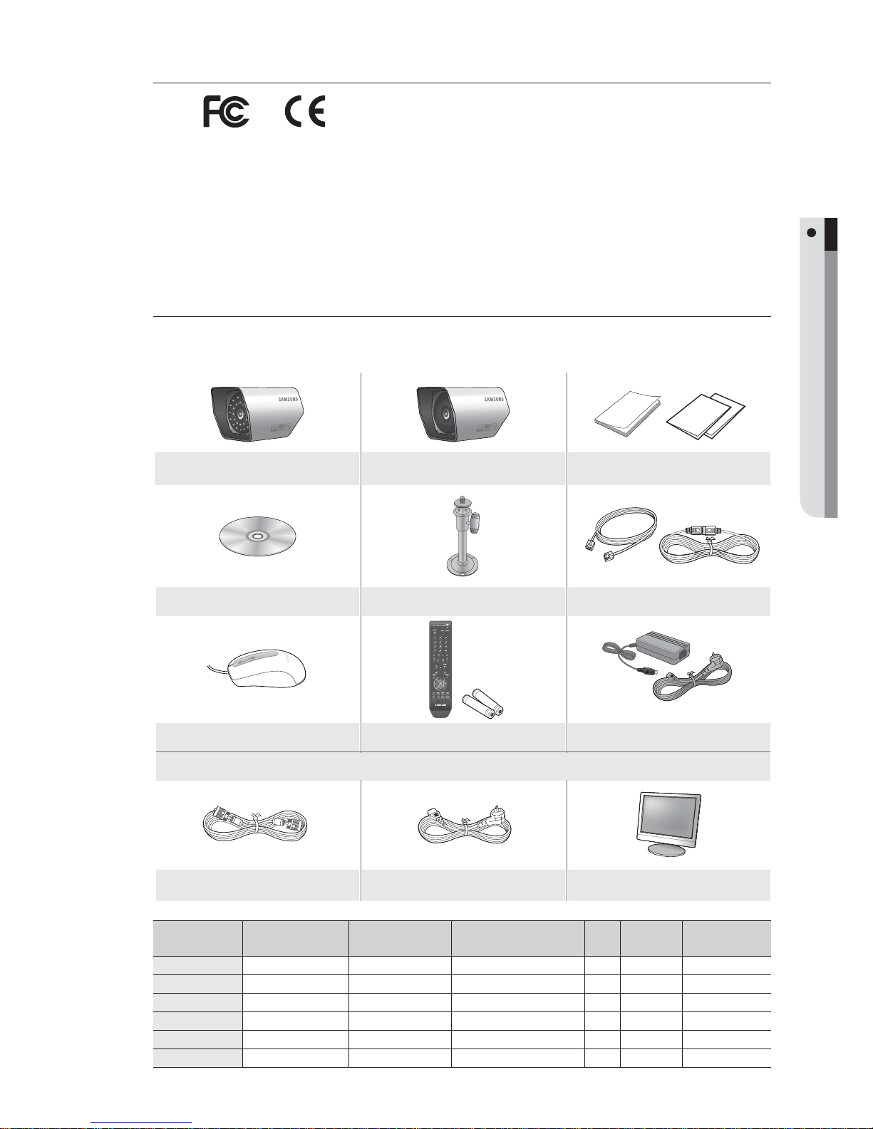
Package Contents
Please unwrap the product, and place the product on a flat place or in the place to be installed.
Please check the following contents are included in addition to the main unit.
SOC-A100(P)* SOC-A101(P)*
User Manual / Quick Guide* /
Network Setup Guide*
CD* Camera Bracket* Ethernet Cable / Mini Din Cable (4EA)
Mouse Remote Control / Battery (AAA×2)
Adaptor / Power Cable
SMT-1712SE P*
VGA Cable Power Cable MONITOR
M
SOC-A100(P)* SOC-A101(P)*
Quick Guide* /
Network Setup Guide*
CD*
Camera
Bracket*
SMT-1712SE P*
SDE-120N SOC-A100* 2EA SOC-A101* 2EA
{/{
°
4
°
SDE-3000N SOC-A100* 4EA –
{/{
°
4
°
SDE-3001N SOC-A100* 4EA –
{/{
°
4
°
SDE-3002 SOC-A100* 1EA SOC-A101* 1EA
{/°
°
2
°
SDE-3170P SOC-A100P* 4EA –
{/° {
4
{
SDE-3002P SOC-A100P* 2EA SOC-A101P* 2EA
{/° {
4
°
Lo-Call 1890 866 900
www.cctvireland.ie

8_ overview
overview
CONTENTS
OVERVIEW
2
2 Features
3 Important Safety Instructions
6 Before Start
10 Part Names and Functions (Front)
11 Part Names and Functions (Rear)
12 Remote Control
13 DIY Camera
14 Camera Bracket
CONNECTING WITH OTHER DEVICE
16
16 Connecting the Camera, Audio, Speaker,
Mouse, and Power Cable
16 Connecting the Alarm I/O
17 Network Connection
GETTING STARTED
19
19 Starting the System
19 Log On
20 Log In
20 Log Off
20 Power Off
LIVE
21
21 Live Screen Configuration
22 View the Launcher Menu
23 Display
23 Record
24 Playback
24 Playback Screen
DVR SETUP
25
25 Before Starting Setting Up
25 System Setup
26 System
29 Camera
32 Display
35 Sound
36 User
38 Network
42 Event / Sensor
46 Disk Management
47 Record Setup
Lo-Call 1890 866 900
www.cctvireland.ie

English _9
OVERVIEW
BACKUP
51
51 Backup
SEARCH & PLAY
53
53 Search
WEB VIEWER
55
55 Introduction
58 Live Viewer
61 Search Viewer
62 Search by Time
62 Search by Event
63 Setup
69 Information
70 Using the iPhone
APPENDIX
71
71 Camera Specification
72 Product Specification
(SDE-120N/SDE-3000N/SDE-3001N)
74 Product Specification
(SDE-3170P/SDE-3002P/SDE-3002)
76 Open Source License Report on the Product
Lo-Call 1890 866 900
www.cctvireland.ie
10_ overview
overview
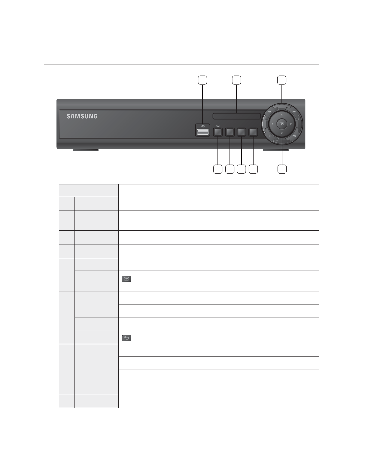
PART NAMES AND FUNCTIONS (FRONT)
Part Names Functions
Power Used to turn on or off the system.
b
DISPLAY
Each time you press in Live mode, the screen will be switched in the sequence of 4-split, Single
and Auto Sequence in order.
c
SERACH Goes to the search screen.
MENU Goes to the system menu screen.
Direction
▲▼◄► : Used to select a system menu item.
Enter
: Selects and runs a menu item.
This will operate as Book mark (Reverse) button during playback.
Speed Playback
: Used for quick forward playback.
: Used for quick backward playback.
Freeze
: Freezes the screen or resumes playing.
Return
: Used to move one level up in the menu screen.
LED
NETWORK : Displays both network connection and data transfer status.
REC : Flashes while the recording is in progress.
ALARM : Flashes if an event occurs.
POWER : Displays the status (ON/OFF) of power connection.
USB Port Used to connect a USB storage device.
DIGITAL VIDEO RECORDER
POWER
ALARM
REC
NETWORK
DISPLAY
SEARCH
MENU
152 3 4
78 6
Lo-Call 1890 866 900
www.cctvireland.ie
English _11
OVERVIEW
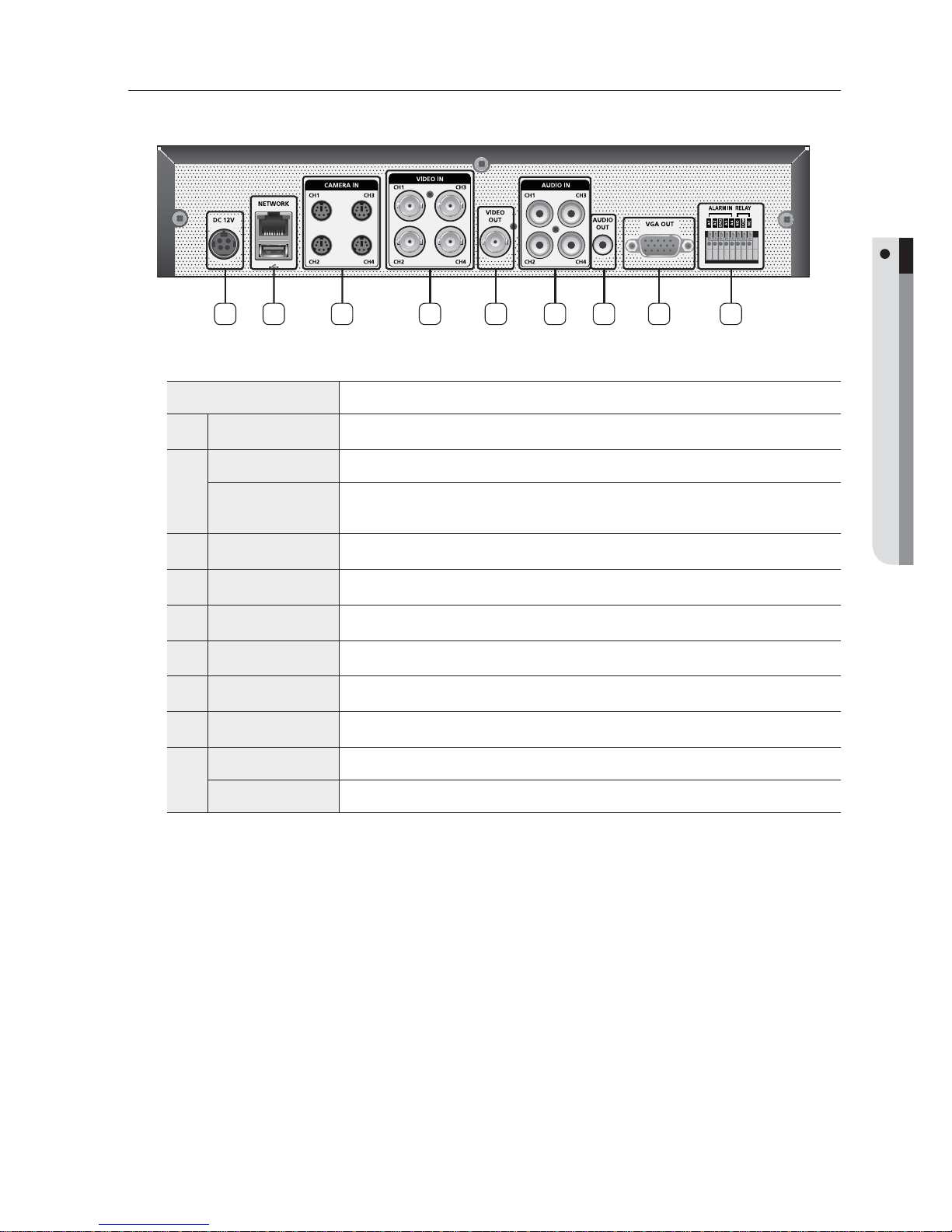
PART NAMES AND FUNCTIONS (REAR)
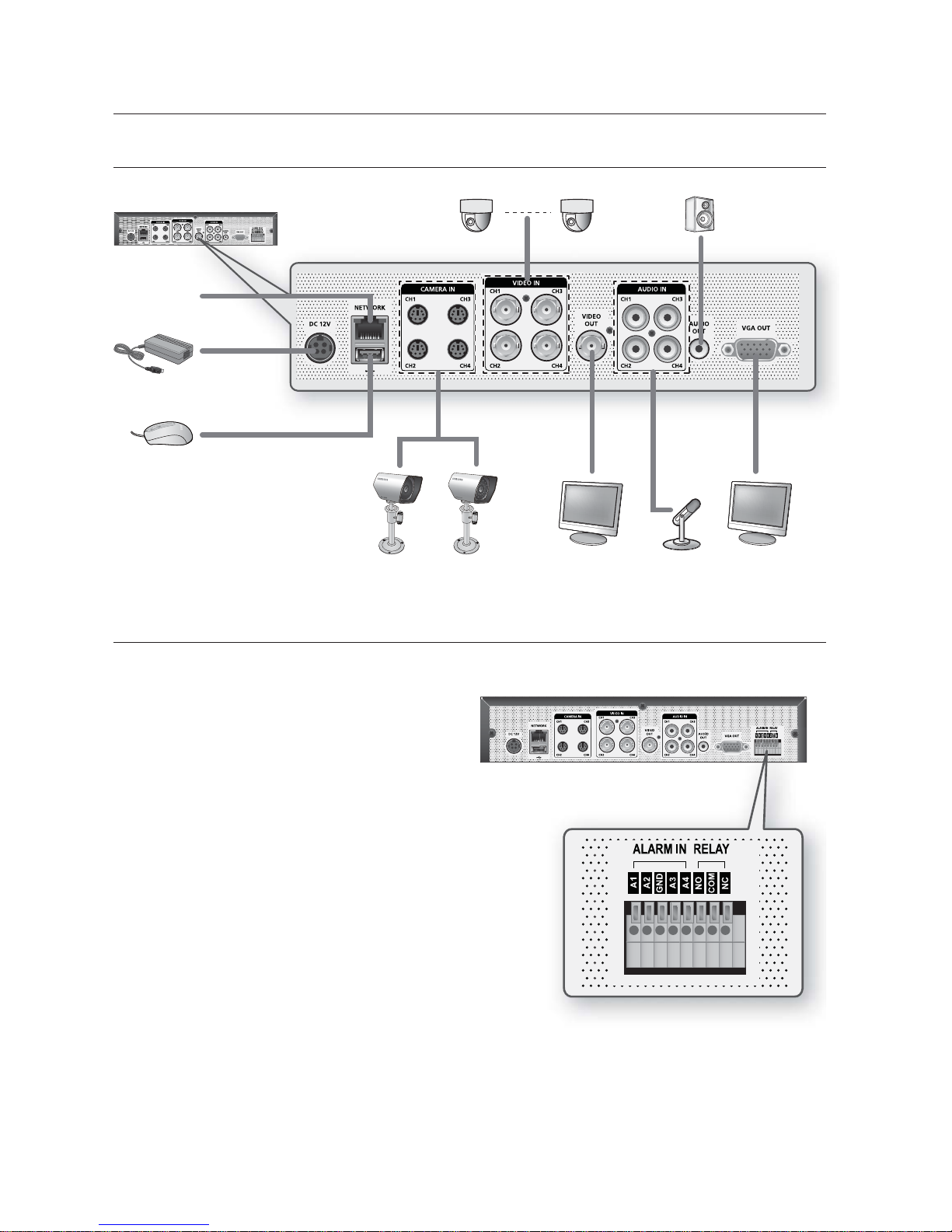
Part Names Functions
DC Input (DC12V) Power connection port for 12V/4A adaptor
b
NETWORK RJ-45 port for network connection.
USB
Supports USB 2.0 protocol that enables you to back up the video signal stored in the HDD
using an external memory device and to connect USB memory.
c
CAMERA IN (1~4) Connector linked to the Port DIY CAMERA
VIDEO IN Composite video signal input port (BNC type port).
VIDEO OUT Composite video signal output port (BNC type port).
AUDIO IN Audio signal input port (RCA jack).
AUDIO OUT Audio signal output port (RCA jack).
VGA OUT Video output port for video output to a VGA monitor.
ALARM IN Alarm input port
RELAY Alarm output port
1 2 3 4 5 6 7 8 9
Lo-Call 1890 866 900
www.cctvireland.ie
12_ overview
overview
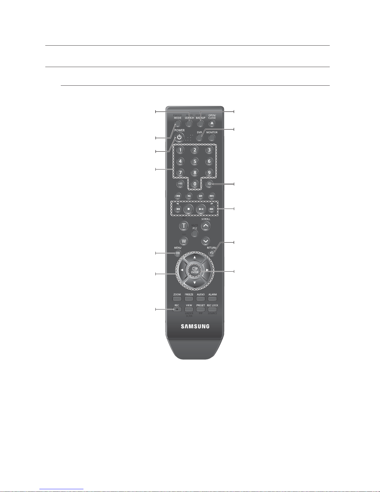
REMOTE CONTROL
DVR
Available after switching to DVR mode by pressing the [DVR] button on the remote control.
SEARCH
Switches to search mode for video search.
At the moment, you should select an authorized user
and enter the password.
MODE
Changes the display mode.
Channel
If you press a channel number in real time monitoring
or search mode, the camera’s input of the selected
channel is displayed in full screen.
MENU
You will see various menu items including settings,
search and backup.
Directions
Used to move between menu items in searching for
or playing recorded video.
BACKUP
Switches to backup mode.
ID
Sets the ID.
Select 2 digits from 0~9 while pressing the ID Key.
RETURN
Cancels the setting and moves to the previous
screen.
ENTER
Selects a menu item or applies your setting.
Play
Plays the search screen or adjusts the speed.
REC
Performs the recording.
DVR
Activates the DVR function.
POWER
Turns on/off or logout the system.
Lo-Call 1890 866 900
www.cctvireland.ie
English _13
OVERVIEW
Changing Remote Control ID
In a multi-DVR system using a single remote control, you can control only the DVR that matches the ID that
you have set using the ID button.
Press the [ID] button to check the ID of each of "REMOCON ID" and "SYSTEM ID".
The defaults are 00 for the System ID and 00 for the Remote ID, respectively.
To change the Remote ID of the IR REMOTE CONTROLLER, press and hold the [ID] button while entering
a desired combination of two digits from 00 to 99.
To change the ID of the DVR, refer to "REMOTE CONTROLLER > REMOTE CONTROLLER ID".
(Page 28)
Press the ID button of the IR REMOTE CONTROLLER to check the ID.
If the system number defined in "REMOTE CONTROLLER" is different from the number specified using the remote
control, no other button than the [ID] buttons will operate.
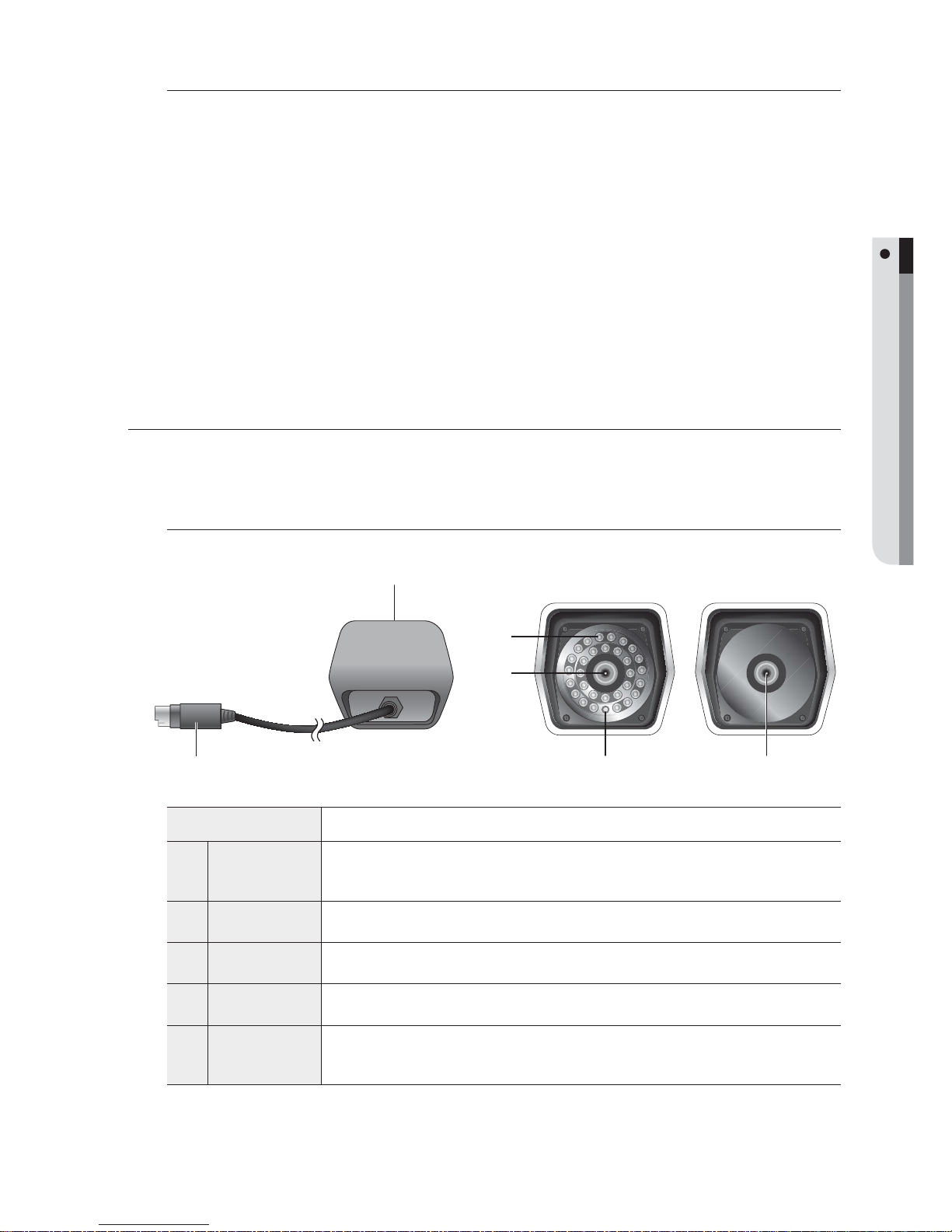
DIY CAMERA
Equipped with the IR LED and the illumination sensor, enables you to monitor at night as well as in daytime.
You can also use it indoors as well since it is designed for outdoor use.
Part Names
Name Description
Camera Fitting
Groove
Groove that is used to fit the camera bracket.
There exist two grooves; one on the top and one on the bottom.
b
IR LED
These are infrared LED's those are controlled by the illumination sensor.
c
Lens
Focal length of 3.8mm enables you to cover relatively longer range of monitoring.
Illumination
Sensor
Detects incoming light to control the IR LED.
DVR Connection
Cable
Connect the cable directly to the DVR without using a particular power cable.
You can use the mini DIN cable to connect to a remote camera.
1.
2.
3.
4.
M
b
c
c
SOC-A100 SOC-A101
Lo-Call 1890 866 900
www.cctvireland.ie
14_ overview
overview
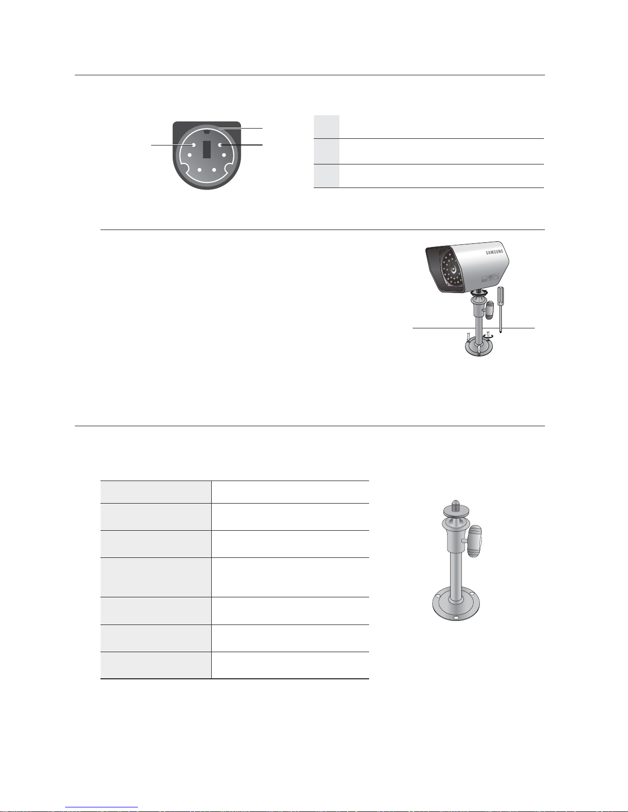
Mini Din Cable
SHIELD
b
12V
c
VIDEO
Installing the camera
The camera can be installed on the wall, ceiling, shelf or a desired
position using the provided bracket.
Select a position where you want to install the camera.
Make sure the selected position can sustain the weight of the camera.
Use the screw bolts (M4 × L15) to mount the camera bracket onto
the wall or ceiling.
Place the camera on the selected position and fit the hole either
on the top or the bottom of the camera into the fixing bolt of the
bracket, and turn the camera clockwise.
CAMERA BRACKET
The camera bracket can be used to install the camera on the wall, ceiling or shelf.
Camera Bracket Specifi cation
Name Description
Use
Indoor
Installation
Wall or Ceiling
Dimensions
57(W) × 47.2(H) × 100.5(L) mm/
2.25(W) × 1.86(H) × 3.95(L) inch
Weight
130g (0.29 lbs)
Operating Temperature
-10˚C ~ 50˚C (14˚F ~ 122˚F)
Accessories
SCREW (M4 × L15) : 3 pcs
1.
2.
3.
b
c
M4 × L15 sized
screws
wall or ceiling
Lo-Call 1890 866 900
www.cctvireland.ie
English _15
OVERVIEW
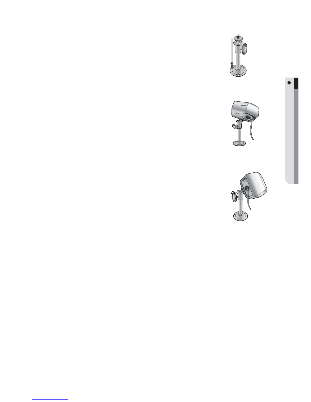
Adjusting the Camera Bracket
Choose an installation site that can sufficiently support the weight of
the equipments to be installed.
Attach the camera bracket to the wall using the supplied screws
(M4 × L15). 4×15 sized screws wall or ceiling.
Adjust the camera to target the video location and tighten the camera
bracket handle on the camera bracket. Install the camera on to the male
screw of the camera bracket by rotating the camera in clockwise.
Loosen the handle by turning it in counter clockwise direction and then
adjust the camera position. Tighten the handle, turning it clockwise, and
lock the camera in position.
Connect the camera cable to the camera.
1.
2.
3.
4.
5.
Handle
Lo-Call 1890 866 900
www.cctvireland.ie
16_ connecting with other device
CONNECTING THE CAMERA, AUDIO, SPEAKER, MOUSE, AND POWER CABLE
CONNECTING THE ALARM I/O
Connecting the alarm Input signal
Connection port for the alarm input signal.
Connect one strand of the sensor signal line (two
strands) to the alarm input port and connect the
other to the [G] port.
Connecting the alarm output signal
Connection port for the alarm output signal.
NO (Normal Open) : Sensor is open in normal
condition, it generates alarm if the sensor is closed.
COM : Connect the grounding cable.
NC (Normal Close) : Sensor is closed in normal
condition, it generates alarm if the sensor is open
by interruption.
•
•
•
connecting with other device
Network
Lo-Call 1890 866 900
www.cctvireland.ie
English _17
CONNECTING WITH OTHER DEVICE
NETWORK CONNECTION
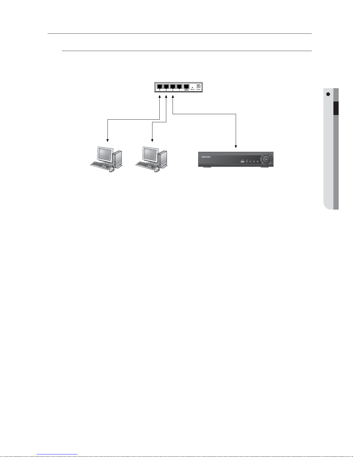
Local System Confi guration
Use the router or hub in the same local network to connect to the DVR and local PC where you can control
the remote DVR or check the recording data in the DVR.
Connect the network port on the rear DVR panel to the router or hub.
Connect the network port on the local PC to the router or hub.
Enter “IP ADDRESS:WEB SERVER PORT” for the DVR on the local PC.
The Web Viewer screen of the DVR appears.
For more information, refer to “Network Connection and Settings”. (Page 40)
1.
2.
3.
M
DIGITAL VIDEO RECORDER
POWER
ALARM
REC
NETWORK
DISPLAY
SEARCH
MENU
Local PC #1
IP Router or HUB
DVR
Local PC #2
Lo-Call 1890 866 900
www.cctvireland.ie
18_ connecting with other device
connecting with other device
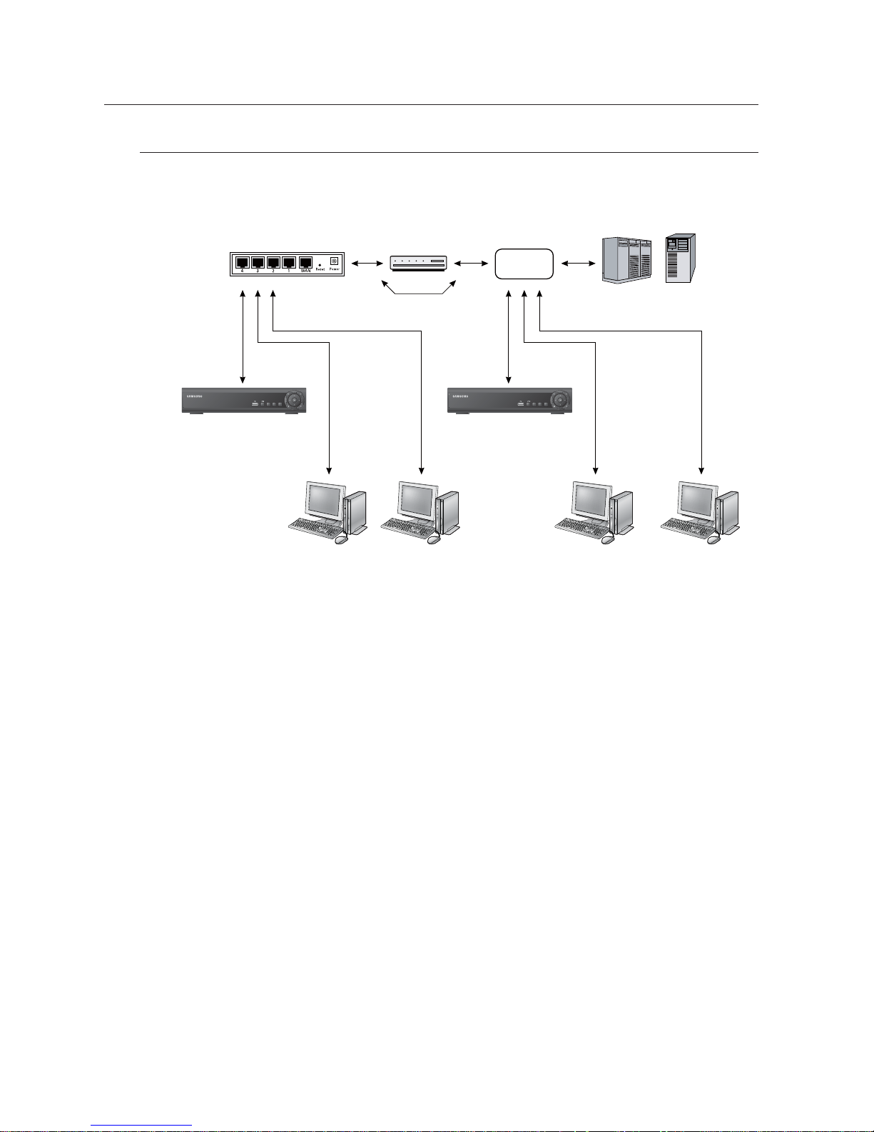
Total System Confi guration
You can use the 10/100 Mbps Ethernet connector on the product to connect to the network.
Connecting to the network enables you to perform various functions including remote monitoring, remote
search and remote control.
Connect LAN cable of Cable/ADSL modem or Direct Fixed/Static IP LAN Line to WAN port of IP Router.
Connect LAN ports of IP Router to Ethernet port DVR to be set up and to Ethernet port of Local PC to use
during setup.
Connect Video cable of Camera to Monitor.
Turn on the Monitor power.
If you have a Static (Fixed) IP line or Dynamic IP line (Cable Modem or ADSL Modem) with one IP address (whether it's
dynamic or fixed), but have more than one internet device to use (such as a PC and a DVR or several DVRs): you must
use an IP Router (different from a simple Network Hub); You must set up the Router to work with the DVR and you must
use a network capable PC within The local Router network to do the setup.
If you are using an existing Router which is already set up, you may not need to redo the basic setup of the Router
again, but it is highly recommended that you at least read all the instructions below and go through the steps. Whether
you are using an existing Router or a new Router, you must go through the Port Forwarding portion of the setup.
1.
2.
3.
4.
DIGITAL VIDEO RECORDER
POWER
ALARM
REC
NETWORK
DISPLAY
SEARCH
MENU
DIGITAL VIDEO RECORDER
POWER
ALARM
REC
NETWORK
DISPLAY
SEARCH
MENU
DDNS Server
(websamsung.net)
Local PC #1 Local PC #2
IP Router or HUB Cable/ADSL Modem
Direct LAN (Fixed/Static IP)
INTERNET
or
External Remote PC #1 External Remote PC #2
DVR DVR
Lo-Call 1890 866 900
www.cctvireland.ie
English _19
GETTING STARTED
getting started
STARTING THE SYSTEM
Connect the power cable of the DVR to the wall outlet.
You will see the initialization screen.
LOG ON
To make use of the DVR, you must log on after the system started.
You must log on before you can use the features of the DVR.
Select a user account that you want to log on with.
Enter the password.
The default user is “admin” and password is “4321”.
1.
2.
1.
2.
admin
USER ID
PASSWORD
. @ # $ % & * ( )
1 2 3 4 5 6 7 8 9 0
A B C D E F G H I
J K L M N O P Q R /
S T U V W X Y Z _ a
ENTER
CANCEL
LOG ON
Lo-Call 1890 866 900
www.cctvireland.ie
20_ getting started
getting started
LOG IN
To access menu items of Logout, System Setup, Record Setup, Backup and Search, you must have logged in.
If you try to access restricted menus, the login dialog
pops up.
Select a user account, enter the password and press the
<ENTER> button.
The default user is “admin” and password is “4321”.
The user who has a limited access to the menu will not be
displayed in the user list.
The menu screen to access appears.
LOG OFF
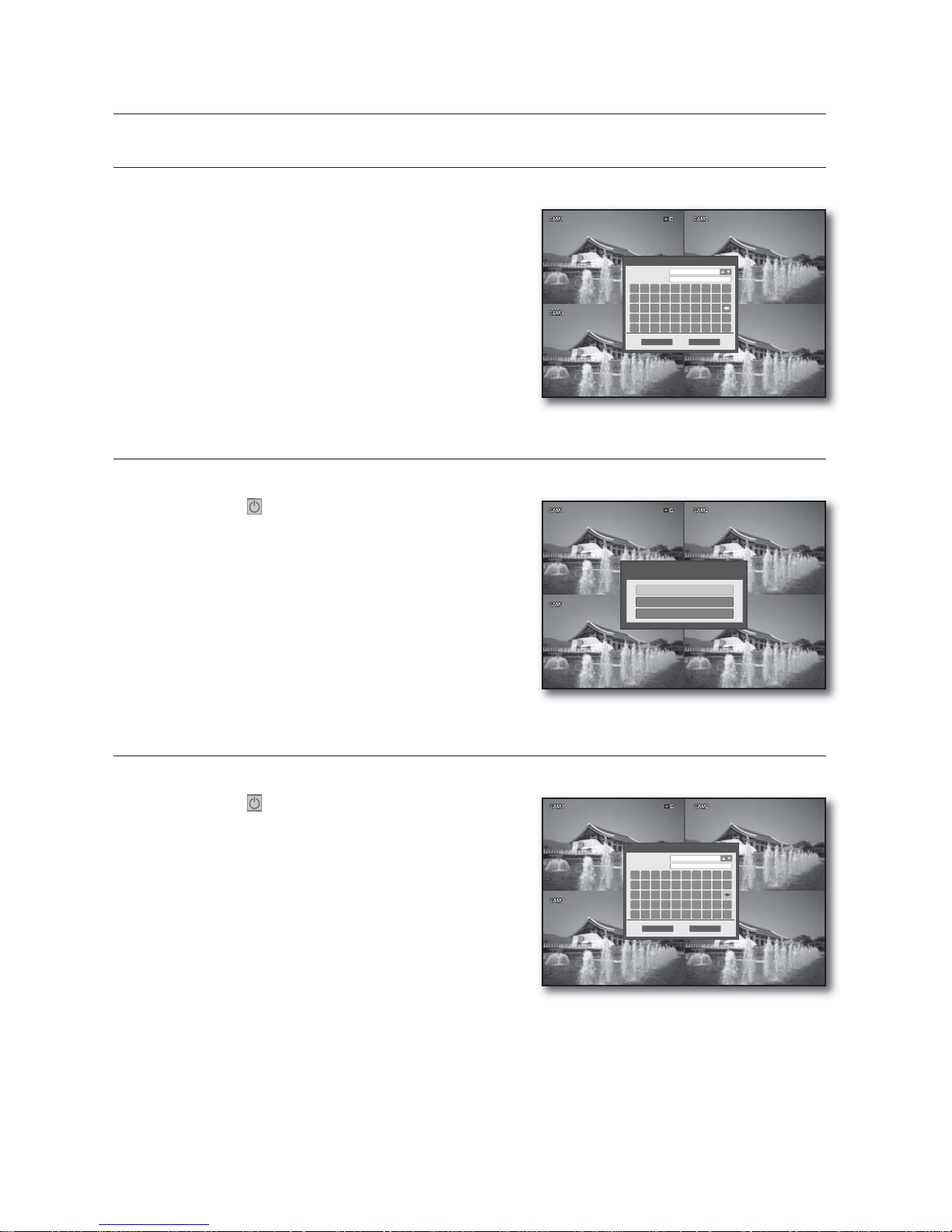
If you do not use the system for an extended time, please log out to restrict access from other users.
Press the <
> button on the launcher menu or press
the [POWER] button on the remote control.
Press the <LOG OFF> button.
It automatically logs off.
POWER OFF
You can shut down the system only if you have logged in to the DVR.
Press the <
> button on the launcher menu or press the
[POWER] button on the remote control.
Press the <POWER OFF> button.
Enter the password and press the <ENTER> button.
Turn off the power switch.
1.
2.
3.
1.
2.
1.
2.
3.
4.
admin
USER ID
PASSWORD
. @ # $ % & * ( )
1 2 3 4 5 6 7 8 9 0
A B C D E F G H I
J K L M N O P Q R /
S T U V W X Y Z _ a
ENTER
CANCEL
LOG IN
LOG OFF
POWER OFF
EXIT
admin
USER ID
PASSWORD
. @ # $ % & * ( )
1 2 3 4 5 6 7 8 9 0
A B C D E F G H I
J K L M N O P Q R /
S T U V W X Y Z _ a
ENTER
CANCEL
POWER OFF
Lo-Call 1890 866 900
www.cctvireland.ie
English _21
LIVE
live
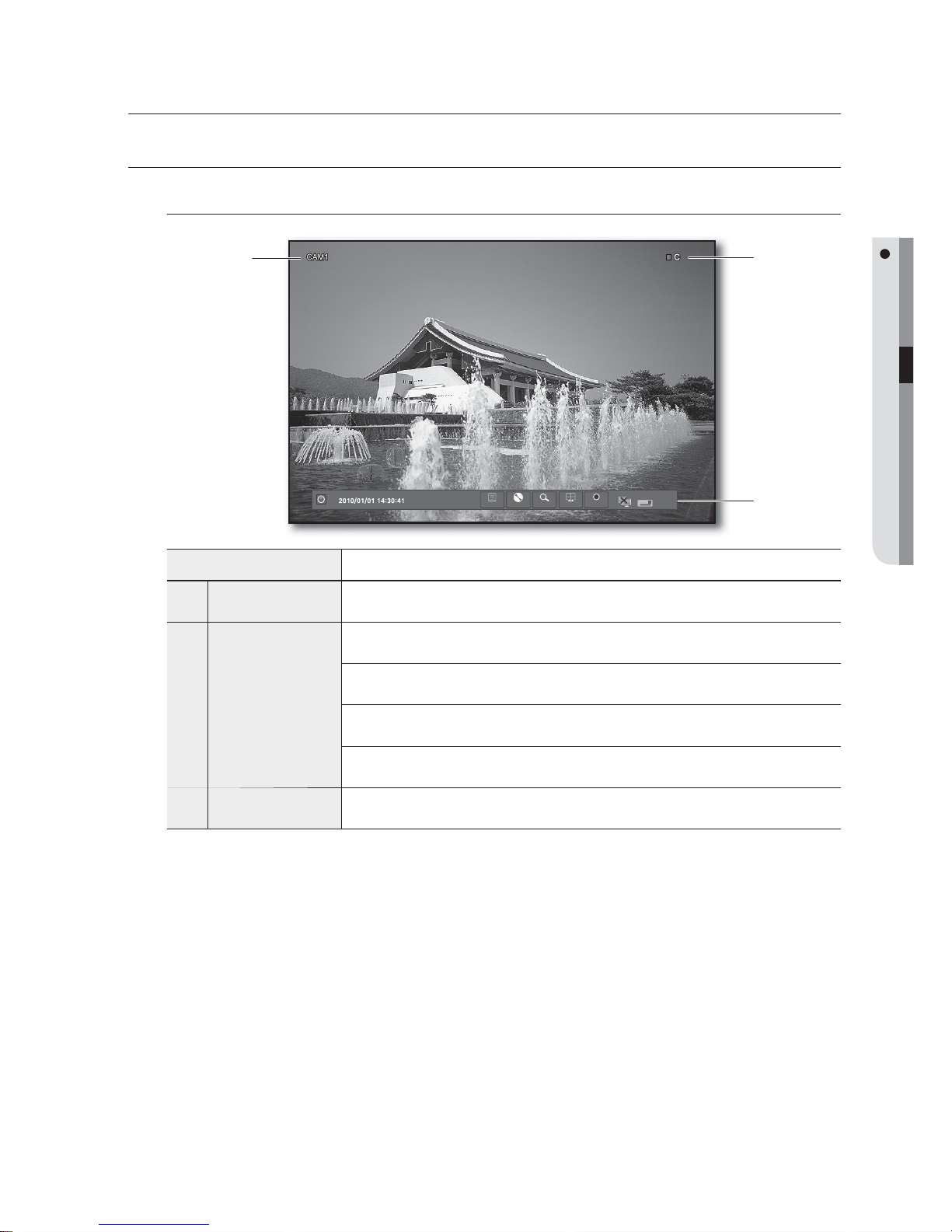
LIVE SCREEN CONFIGURATION
Icons on the Live Screen
Name Description
Camera Name
Displays the name of the camera.
b
Recording Modes
CC : Indicates continuous recording.
AA : Indicates alarm recording.
MM : Indicates motion detection recording.
II : Indicates instant recording.
c
Launcher Menu
Displays the current time, menu and status.
ow
MENU BACKUP SEARCH DISP REC
b
c
Lo-Call 1890 866 900
www.cctvireland.ie
22_ live
live
VIEW THE LAUNCHER MENU
You can use the Launcher menu appearing on the bottom of the live screen to access it.
On the Live screen, move the cursor or press the [MENU]
button on the remote control to display the Launcher menu.
Use the direction buttons or the cursor to select a desired
menu.
You can adjust the display time of the Launcher in “DISPLAY
> OSD > STATUS BAR TIMEOUT”. (Page 32)
Name Description
Logout/Power off
The logout or power-off dialog appears.
b
Date/Time
Displays the current time.
c
MENU
Displays the system, record setup menu window appears.
BACKUP
Accesses the backup screen.
SEARCH
Accesses the search screen.
DISP
Displays a dialog to switch between split mode and sequence.
REC
Starts the manual recording.
Network Status
Indicates the Web Viewer connection status.
HDD
Displays HDD mode whether it is overwrite or not.
1.
2.
M
ow
MENU BACKUP SEARCH DISP REC
cb
ow
MENU BACKUP SEARCH DISP REC
Lo-Call 1890 866 900
www.cctvireland.ie

English _23
LIVE
DISPLAY
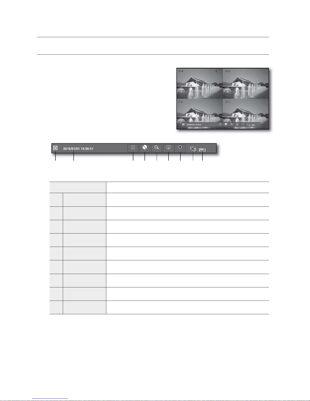
You can select a screen split mode or perform the auto sequence function.
Switching the screen mode
You select a screen mode from single and 4-split.
Press the <DISP> button from the Launcher menu.
Select a split mode in the split option menu.
Press the [MODE] button on the front panel or the
remote control to switch the mode in the sequence of the
launcher menu items.
Auto Sequence
You can perform the auto sequence function.
Press the <DISP> button from the Launcher menu or press the [MODE] on the remote control.
When the split mode selection menu appears, press the <
>
button.
The screen mode switches to Single while transition.
You can adjust the screen transition interval in “SYSTEM SETUP >
DISPLAY > MONITOR > SEQUENCE DWELL”. (Page 33)
You can also add a sequence using the same menu.
RECORD
In addition to the existing recording, you can proceed with recording directly in Live mode.
Press the <REC> button from the Launcher menu or
press the [REC] on the remote control.
This can be done by right-clicking any area to display the context
menu where you select <RECORD START>.
When the recording starts, <RECORD START> will switch to
<RECORD STOP>.
The recording starts immediately with the <I> mark
displayed on the top right corner.
To stop recording, press the <REC> button or click
<RECORD STOP>.
1.
2.
1.
2.
M
1.
2.
3.
CH4
CH3
CH2
CH1
4
1
Single mode
ow
MENU BACKUP SEARCH DISP REC
ow
MENU BACKUP SEARCH DISP REC
Lo-Call 1890 866 900
www.cctvireland.ie
24_ live
live
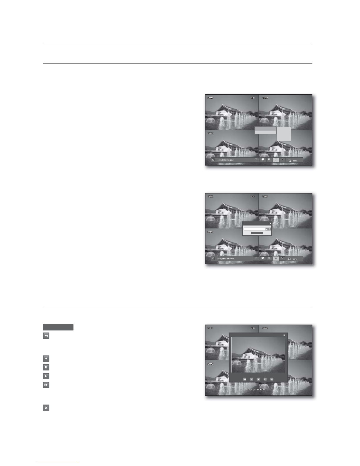
PLAYBACK
In Live screen, you can immediately play any of the previous recordings in the selected channel.
To playback by time option
Select a channel to play, and right-click it to display the
context menu where you select <PLAYBACK>.
Select a desired start time of playback.
To playback by time selection
You can select <GO TO..> if you want to select a
playback start time.
When the “TIME SELECTION” window appears, specify
the start time and click <OK>.
The playback screen appears from the selected time
point.
PLAYBACK SCREEN
You can adjust the play speed of the instant recording screen that is currently played.
2010/01/01 10:28:02
: Shows the playback time.
: Plays backward in the following speed
X2, X4, X8, X16, X32, X64
Reduces the speed in forward playback.
: Plays backward.
: Pauses playing temporarily.
: Plays forward.
: Plays forward in the following speed
X2, X4, X8, X16, X32, X64
Reduces the speed in backward playback.
: Closes the playback screen.
In “INSTANT PLAYBACK” mode, SDE-120 plays the video without the audio.
1.
2.
1.
2.
3.
M
10SEC AGO
20SEC AGO
30SEC AGO
1MIN AGO
GO TO ..
ow
MENU BACKUP SEARCH DISP REC
PLAYBACK >
RECORD START
TIME SELECTION
2010/01/01 10:28:02
OK
ow
MENU BACKUP SEARCH DISP REC
CH 1
2010/01/01 10:28:02 > x1
Lo-Call 1890 866 900
www.cctvireland.ie
English _25
DVR SETUP
BEFORE STARTING SETTING UP
You can configure the DVR settings to your preference.
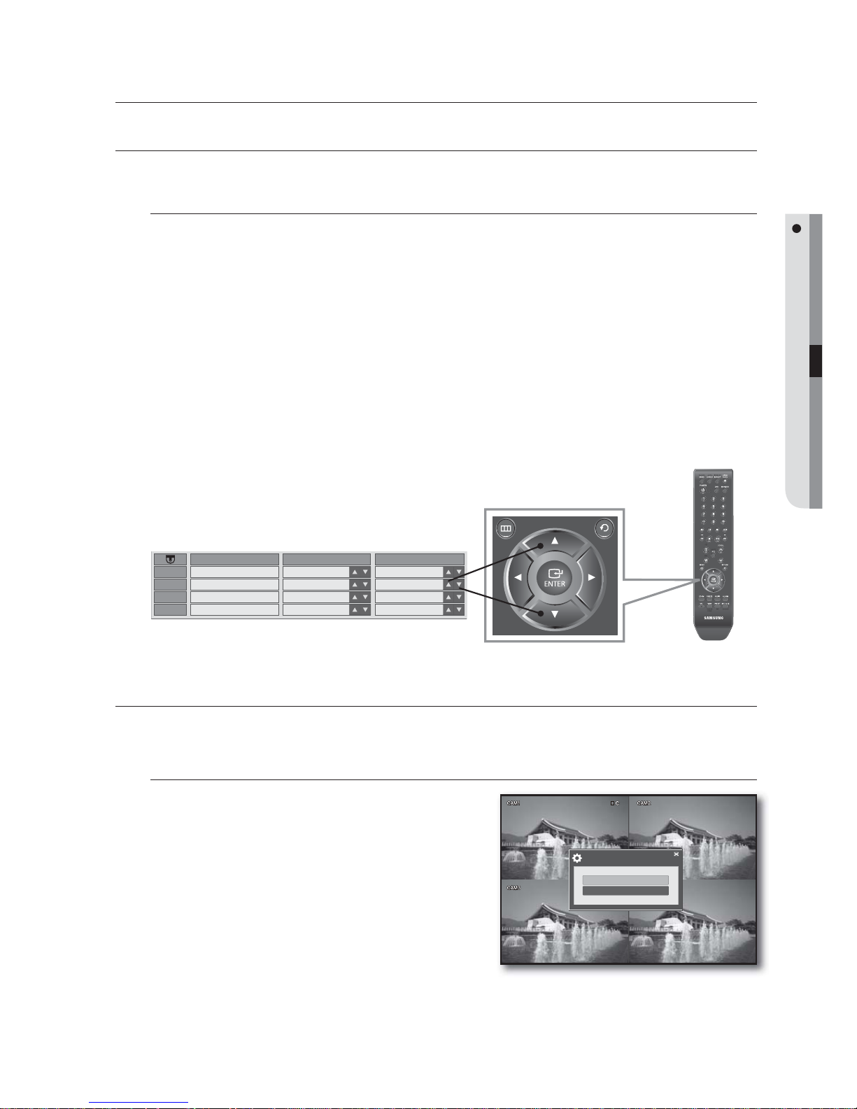
How to use remote control and mouse
You can use either the remote control or the cursor to select or change the setting of each menu item.
To change the setting using the remote control
Use the four direction (▲▼◄►) buttons to move to a desired item and press the [ENTER] button.
You must press the [ENTER] button to confirm the selected item.
Use the up/down (▲▼) buttons to adjust the given option values.
UP (▲) : Adjusts to the previous value of the selected item.
DOWN (▼) : Adjusts to the next value of the selected item.
Change the setting and press [ENTER] before your change can be applied.
To return to the previous menu, press the [RETURN] menu.
The player will return to the previous menu without saving your changes.
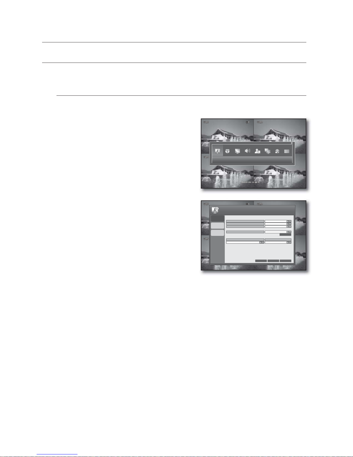
SYSTEM SETUP
You can configure the System menu settings to your preference.
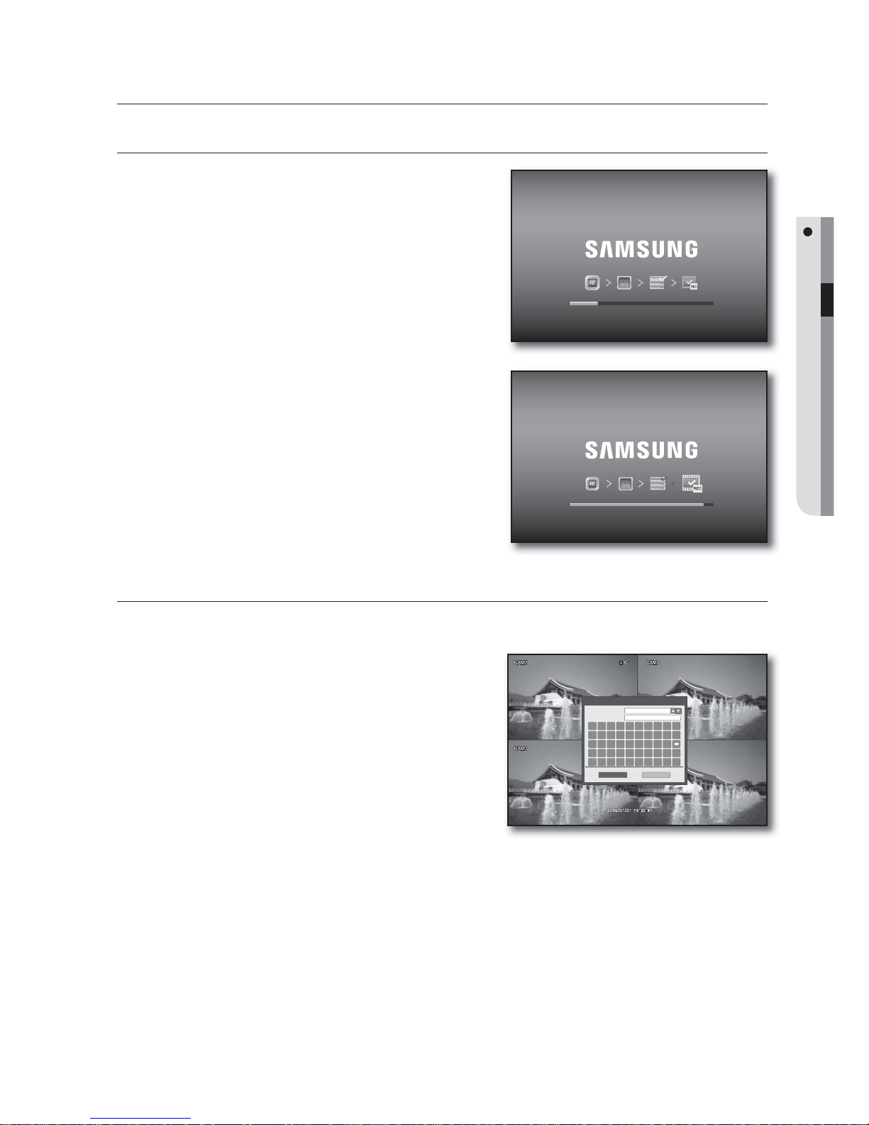
To start the SYSTEM SETUP
Press the [MENU] button on the remote control or press
the <MENU> button on the launcher menu.
The SETUP menu screen appears.
Use the direction buttons to move to <SYSTEM SETUP>
and press the [ENTER] button.
The login dialog appears.
Select a user account and enter the password.
Only those users who have the right permissions can access
the Setup menu.
1.
2.
•
•
3.
4.
1.
2.
3.
DVR setup
TITLE
COVERT
AUDIO
CAM 1
CAM 2
CAM 3
CAM 4
OFF
OFF
OFF
OFF
CH 1
CH 1
CH 1
CH 1
CH 1
CH 2
CH 3
CH 4
SYSTEM SETUP
RECORD SETUP
SETUP
Lo-Call 1890 866 900
www.cctvireland.ie
26_ DVR setup
DVR setup
SYSTEM
You can configure the settings of DATE/TIME, SYSTEM MANAGEMENT and REMOTE CONTROLLER.
See the previous section to repeat steps 1~3. (Page 25)
DATE/TIME
You can specify the display time.
Using the mouse may help easy setup.
Use the direction buttons to move to the upper
<SYSTEM> icon and press the [ENTER] button.
The DATE/TIME setup screen appears.
Use direction buttons (▲▼◄►) to move to a desired
item, and press the [ENTER] button to set the value.
DATE TIME: Set the current time and date.
DATE FORMAT: Set the date format.
YYYY/MM/DD, DD/MM/YYYY, MM/DD/YYYY
TIME FORMAT: Set the time format to either AM/PM or
24 hours.
NETWORK TIME SERVER SETUP: Set the current time
using the time server.
If you press the <SYNC.> button while connected to
Internet, the time will be set from the time server.
If the player has an existing recording data in the same time schedule, you are prompted to delete it.
Please check the followings if NTP does not work properly.
IP ADDRESS, GATEWAY, SUBNET MASK, 1st DNS SERVER, 2nd DNS SERVER of IP SETUP in NETWORK menu.
TIME ZONE SETUP: Set the GMT standard time of your area.
D.S.T: Turn on or off the daylight saving time.
When your settings are completed, press the <APPLY> button on the bottom.
Your settings will be applied.
Press the <CLOSE> button to display the confirmation dialog and return to the previous menu.
1.
2.
•
•
•
•
•
•
3.
4.
SYSTEM
DATE / TIME
SYSTEM
MANAGEMENT
2010/01/01 08:17:10
YYYY/MM/DD
24 HOUR
POOL.NTP.ORG
DATE TIME
DATE FORMAT
TIME FORMAT
NETWORK TIME SERVER SETUP
CANCEL APPLY CLOSE
SYSTEM
D . S . T
OFF
TIME ZONE SETUP
GMT+06:00 AMERICA/CST
REMOTE
CONTROLLER
SYNC.
Lo-Call 1890 866 900
www.cctvireland.ie
English _27
DVR SETUP
SYSTEM MANAGEMENT
You can check, update and initialize the system information.
Using the mouse may help easy setup.
Use the direction buttons to move to <SYSTEM
MANAGEMENT> in the left corner of the SYSTEM setup
menu and press the [ENTER] button.
Use direction buttons (
▲▼◄►
) to move to a desired item,
and press the [ENTER] button to set the value.
SYSTEM INFORMATION: Can check the current
system version and system-related settings.
Press the <INFO> to display the “SYSTEM
INFORMATION” window.
S/W VERSION: Displays the software version.
H/W VERSION: Displays the hardware version.
VIDEO SIGNAL TYPE: Displays the signal type of the
current video.
DISK CAPACITY: Displays the capacity of the HDD.
IP ADDRESS: Displays the IP address of the DVR.
MAC ADDRESS: Displays the DVR’s MAC address.
DDNS SERVER: Displays the domain name of the appropriate set.
RTSP SERVICE PORT: Indicates the number of a port used when the remote management software
program accesses the DVR.
WEB SERVER PORT: Indicates the number of a port used to connect to the DVR using the web
browser.
SYSTEM NAME: Set the system name using virtual keyboard. You can type in up to 15 bytes.
FIRMWARE UPDATE: You can upgrade the current software version.
For more information about the firmware update, refer to “To update the firmware”. (Page 28)
FACTORY DEFAULT: Restore the DVR settings to the factory default.
SYSTEM DATA: Save the system setup data or import the system information of other device.
SAVE : Stores the setting information of the DVR into the storage device.
Connect the storage device to the USB port of the system.
LOAD : Applies the setting information in the storage device to the DVR.
Connect the device to store the system data to the USB port.
PASSWORD: Turns on or off the popup of the “LOG IN” dialog if you access a menu item such as
Power Off, System Setup, Record Setup, Backup, Search.
AUTO LOGOUT: Select to set the auto logout when no input is made after you logged in.
DURATION: Specify the period for the auto logout.
When your settings are completed, press the <APPLY> button on the bottom.
Your settings will be applied.
Press the <CLOSE> button to display the confirmation dialog and return to the previous menu.
1.
2.
•
-
-
-
-
-
-
-
-
-
•
•
•
•
-
-
•
•
•
3.
4.
SYSTEM ID
SYSTEM INFORMATION
SYSTEM NAME
FIRMWARE UPDATE
CANCEL APPLY
CLOSE
SYSTEM
DATE / TIME
SYSTEM
MANAGEMENT
REMOTE
CONTROLLER
ON
FACTORY DEFAULT
SYSTEM DATA
PASSWORD
LOAD
NETWORK
SAVE
USB
LOAD
INFO
ON
AUTO LOGOUT
1 MIN
DURATION
SYSTEM ID
SYSTEM INFORMATION
SYSTEM NAME
FIRMWARE UPDATE
CANCEL APPLY
CLOSE
SYSTEM
DATE / TIME
SYSTEM
MANAGEMENT
REMOTE
CONTROLLER
ON
FACTORY DEFAULT
SYSTEM DATA
PASSWORD
LOAD
NETWORK
SAVE
USB
LOAD
INFO
ON
AUTO LOGOUT
1 MIN
DURATION
SYSTEM INFORMATION
SDE-120_V0.10_XXXXXX
S/W VERSION
MAMD500
H/W VERSION
NTSC
VIDEO SIGNAL TYPE
244 GB
DISK CAPACITY
192.168.1.200
IP ADDRESS
00115ff00378
MAC ADDRESS
websamsung.net
DDNS SERVER
554
RTSP SERVICE PORT
8080
WEB SERVER PORT
Lo-Call 1890 866 900
www.cctvireland.ie
28_ DVR setup
DVR setup
To update the firmware
Connect the device storing the update files to the USB
port.
Press <USB> button in system management menu.
Select device, you will see the firmware list.
Select update file in <FIRMWARE LIST>.
Press <UPDATE> button in the Firmware upgrade
window.
The update status bar appears and the system will
perform the upgrade.
When the upgrade is completed, the system restarts.
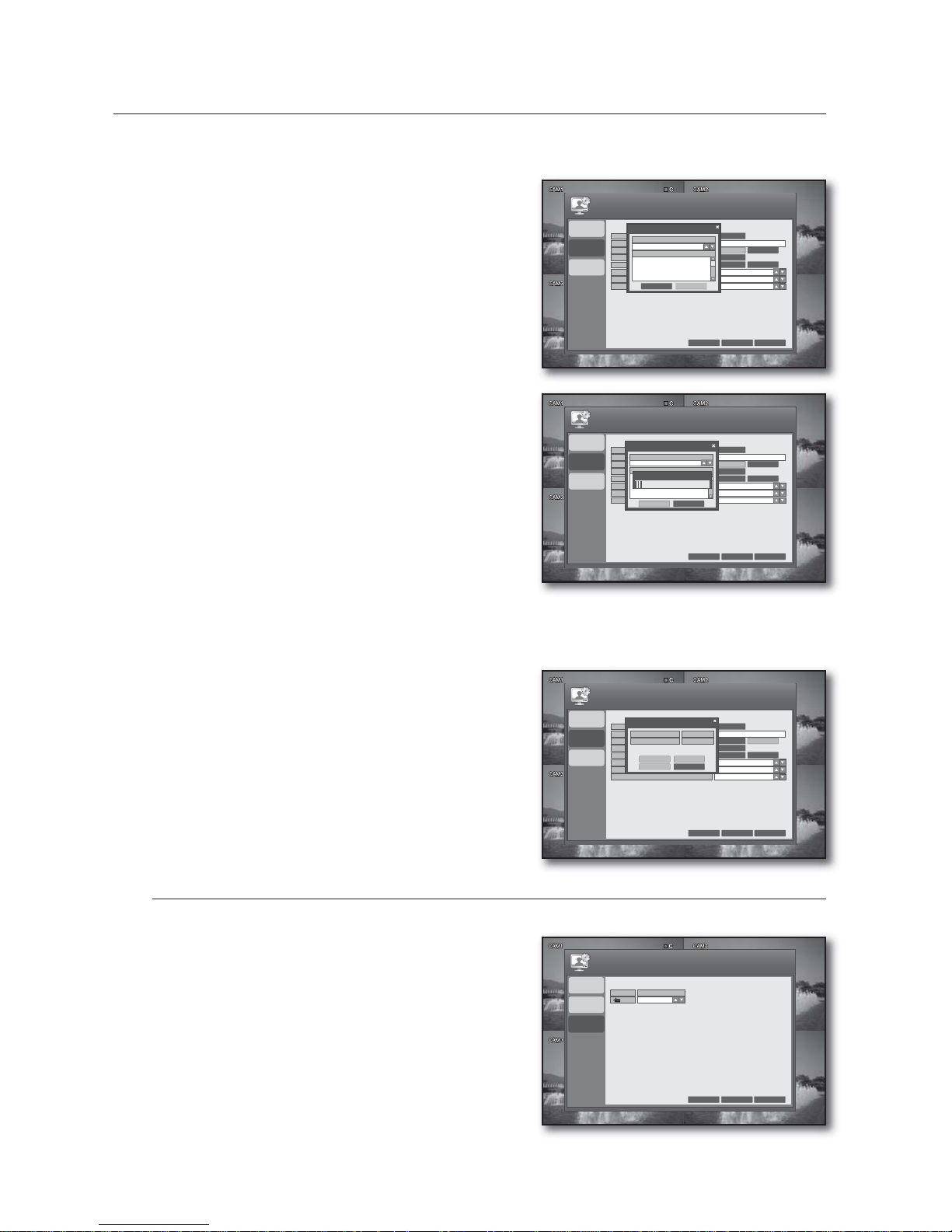
To update the network
Search the network system for an updateable file before proceeding with the update.
Check if the network connection is made properly.
Press the <NETWORK> button.
Click <CHECK> to check if there is any new updateable
file in the network.
REMOTE CONTROLLER
Using the mouse may help easy setup.
Use the direction buttons to move to <REMOTE
CONTROLLER> in the left corner of the SYSTEM setup
menu and press the [ENTER] button.
Use direction buttons (▲▼◄►) to move to a desired
item, and set the <REMOTE CONTROLLER ID>.
When your settings are completed, press the <APPLY>
button on the bottom.
Your settings will be applied.
Press the <CLOSE> button to display the confirmation
dialog and return to the previous menu.
1.
2.
3.
4.
5.
6.
7.
1.
2.
1.
2.
3.
4.
DEV.
CANCEL APPLY
CLOSE
SYSTEM
REMOTE CONTROLLER ID
0
DATE / TIME
SYSTEM
MANAGEMENT
REMOTE
CONTROLLER
SYSTEM ID
SYSTEM INFORMATION
SYSTEM NAME
FIRMWARE UPDATE
CANCEL APPLY
CLOSE
SYSTEM
DATE / TIME
SYSTEM
MANAGEMENT
REMOTE
CONTROLLER
ON
FACTORY DEFAULT
SYSTEM DATA
PASSWORD
LOAD
NETWORK
SAVE
USB
LOAD
INFO
ONAUTO LOGOUT
1 MINDURATION
FIRMWARE UPDATE
SELECT DEVICE
USB MEMORY
FIRMWARE LIST
UPDATE
CANCEL
SYSTEM ID
SYSTEM INFORMATION
SYSTEM NAME
FIRMWARE UPDATE
CANCEL APPLY
CLOSE
SYSTEM
DATE / TIME
SYSTEM
MANAGEMENT
REMOTE
CONTROLLER
ON
FACTORY DEFAULT
SYSTEM DATA
PASSWORD
LOAD
NETWORK
SAVE
USB
LOAD
INFO
ONAUTO LOGOUT
1 MINDURATION
FIRMWARE UPDATE
SELECT DEVICE
USB MEMORY
FIRMWARE LIST
UPDATE
CANCEL
15110.1.1.71
F/W UPGRADE
SYSTEM ID
SYSTEM INFORMATION
SYSTEM NAME
FIRMWARE UPDATE
CANCEL APPLY
CLOSE
SYSTEM
DATE / TIME
SYSTEM
MANAGEMENT
REMOTE
CONTROLLER
ON
FACTORY DEFAULT
SYSTEM DATA
PASSWORD
LOAD
NETWORK
SAVE
USB
LOAD
INFO
ONAUTO LOGOUT
1 MINDURATION
FIRMWARE UPDATE
CURRENT VERSION
NEW VERSION
SDE-120_V0.10_XXXXXX
0.0.0.0
CHECK DOWNLOAD
UPDATE
CANCEL
Lo-Call 1890 866 900
www.cctvireland.ie
English _29
DVR SETUP
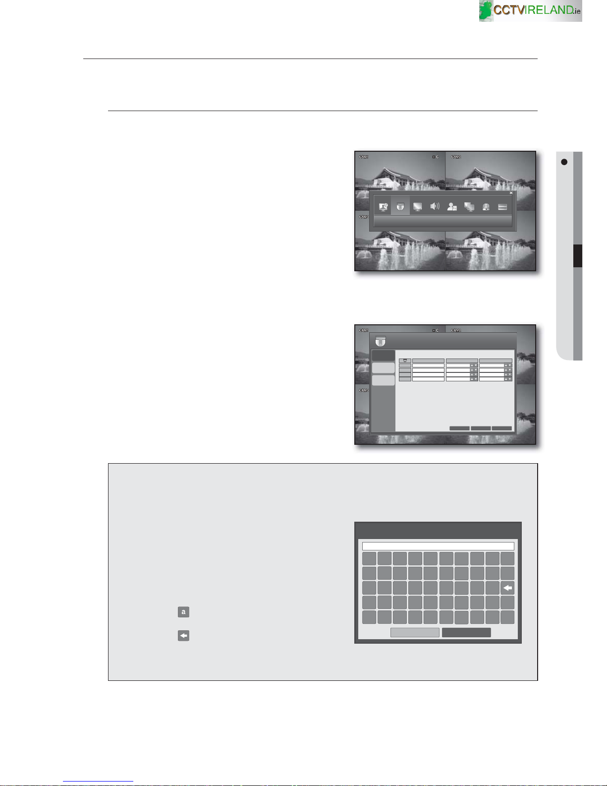
CAMERA
You can configure the settings of each connected CAMERA, COLOR and MOTION SENSOR.
CAMERA
You can configure the camera settings of TITLE, COVERT and AUDIO to your preference.
Using the mouse may help easy setup.
Use the direction buttons to move to the upper
<CAMERA> icon and press the [ENTER] button.
The CAMERA setup screen appears.
To change the camera title
Select an item in the title column.
The virtual keyboard appears.
Use the remote control or the cursor to select a desired
character.
You can enter up to 8 bytes.
Using the Virtual Keyboard
To enter alphanumeric characters for the ID, password and camera name, you can use the cursor or the
remote control.
Use the direction buttons on the remote control to
move to a desired item and press the [ENTER]
button.
Or simply double-click a desired item.
Use the direction button to move to a desired
character and press the [ENTER] button, or simply
click the character.
Selecting <
> will switch the selected character
to the lower case.
Selecting < > will erase the previous character.
When done, press the <ENTER> button on the
bottom.
1.
2.
3.
1.
2.
3.
CAMERA
TITLE
CAMERA
COLOR
MOTION
SENSOR
COVERT
AUDIO
CAM 1
CAM 2
CAM 3
CAM 4
OFF
OFF
OFF
OFF
CH 1
CH 1
CH 1
CH 1
CH 1
CH 2
CH 3
CH 4
CANCEL
APPLY CLOSE
CAMERA
VIRTUAL KEYBOARD
. @ # $ % & * ( )
1 2 3 4 5 6 7 8 9 0
A B C D E F G H I
J K L M N O P Q R /
S T U V W X Y Z _ a
ENTER
CANCEL
CAM1
Lo-Call 1890 866 900
www.cctvireland.ie
 Loading...