

Samsung SDC-7440DC User Manual
SAMSUNG
TECHWIN
Weatherproof 960H
Camera
User Manual
Vari-Focal
SDC-7440DC
CAUTION
authority
user's
the
This
:
NOTE
of
15
part
to
limits
These
operated
This
accordance
Operation
requ1red
in
equipment
of
to
Changes
:
equipment
FCC
the
designed
are
commercial
a
generates,
the
with
equipment
this
correct
modifications
or
operate
to
has
es
l
Ru
to
environment.
instruction
interference
the
void
device,
eqUipment
used
the
case
could
pursuant
1n
user
is
will
4'1'U¥1'U11tJII"'
be
...,..
compliance
expressly
not
equipment.
the
and
tested
been
. (
provide
uses,
in
reasonable
can
and
manual
reSidential
a
his
at
radiate
may
,
own
area
approved
to
found
protection
radio
harmful
cause
likely
is
expense.
comply
by
with
aga1nst
frequency
interference
cause
to
limits
the
harmful
energy
harmful
for
interference
, if
and
radio
to
interference
responsible
part
the
for
digital
A
Class
a
the
when
in
and
which
installed
not
communications.
••n••
E:
..
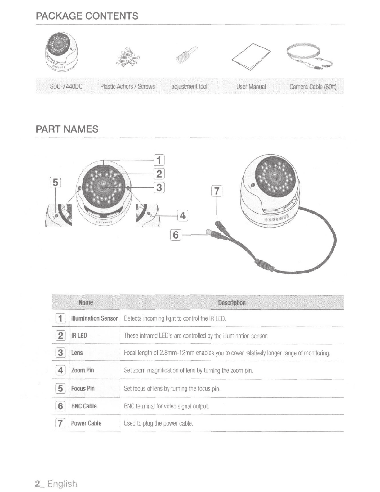
PACKAGE
CONTENTS
SDC-7
4
40DC
PART NAMES
~~
Plastic
~
~
j
~
Achors
I
Screws
~
adjus
/)
)
t
ment
tool
0
User
Manual
Camera
Ca
b
le
(60ft)
[!)
Illumination
[gJ
IR
~
f
lens
Zoom
~
Focus
[ID
BNCCable
(ID
Power
rn
Name
LEO
Pin
Pin
Cable
Sensor
I
Detects
These
I
Focal
Set
Set
BNC
U
se
d
1
incoming
infrared
length
zoom
magnifi
focus
of
terminal
to
plug
light
to
control
LED's
are
controlled
of
2.8mm-12mm
c
ation
of
lens
by
turning
for
vide
o
signa
the
pow
er
cabl
lens
the
l
output.
e.
the
IR
by
the
enables
by
turning
focus
pin
Description
LED
..
illumination
you
to
cover
the
zoom
.
sensor.
relatively
pin
.
longer
range
of
monitoring.
2_
Engli
sh
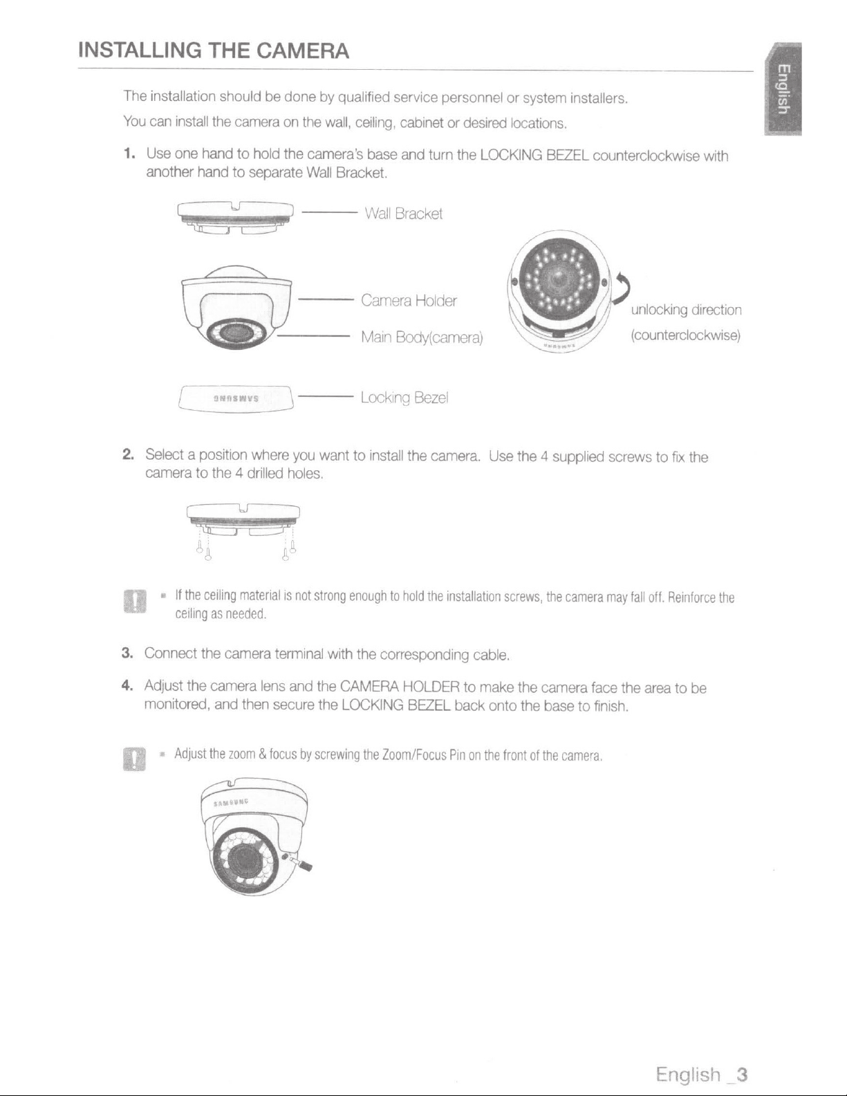
INSTALLING
The
installation should
You
can
install
1.
Use
one
another
THE
the
hand
hand
CAMERA
be
done
camera
to
to
on
hold
the
separate
by
qualified
the
wall,
camera's
Wall
Bracket.
ceiling
base
service
,
cabinet
and
turn
personnel
or
desired
the
LOCKING
or s
ystem
locations.
BEZEL
installers
.
counterclockwise
wrth
2.
~u~
[_~
Select
camera
•
If
the
ceiling
4£3
N
-11
-;
_
a position
to
the
4
ceiling
as
needed
2Y
,.
_
v
_s
_
_J
where
drilled
material
---
---
you
holes.
is
not
want to
strong
enough
Wall
Main
Lock
1nstall
Bracket
Body(
tn
g
Bez
the
to
hold
the
ca
mera
el
camera.
installation
;
Use
the
4
screws,
supplied
the
camera
unlocking
(counterclockwise)
screws
may
fall
to
fix
off.
Reinforce
the
dtrection
the
3.
Connect
4.
Adjust
monitored,
•
the
the
Adjust
camera
camera
and
then
the
zoom
terminal
lens
secure
&
focus
and
by
with
the
the
CAMERA
the
LOCKING
screwing
corresponding
HOLDER
BEZEL
the
Zoom/Focus
cable.
to
make
back onto
Pin
on
the
the
the
front
camera
base
of
the
face
to
f1n1sh
camera
the
area
to
be
.
English
_
3
 Loading...