

Samsung Sdc-33 Alignment and Adjustments
5. Alignment and Adjustments
WARNING: The main board should be replaced if the back focus is twisted.
Note : Ther is no need to adjust the focus for changing the CCD only
5-1 Camera Adjustment
Note : DNP 3100°K light box, 5100°K color temperature conversion filter and adjustment program. A PC is needed
for camera adjustment
- Flash memory format : Configure the system, and store the “bad block” information
- V-Sub voltage adjustment : Adjust the V-Sub voltage of CCD. (Refer to table on page 5-4)
* AE_BTM adjustment : Adjust the offset of image from A/D converter, and set the reference to black
* 3100°K AWB reference measurement : Take a shot of the white chart (3100°K), and extract the reference
at 3100°K.
* AGC gain adjustment : Extract the AGC gain of 0dB, 6dB
* 5100°K adjustment:
Take a shot of the white chart (5100°K), and extract the reference at 5100°K.
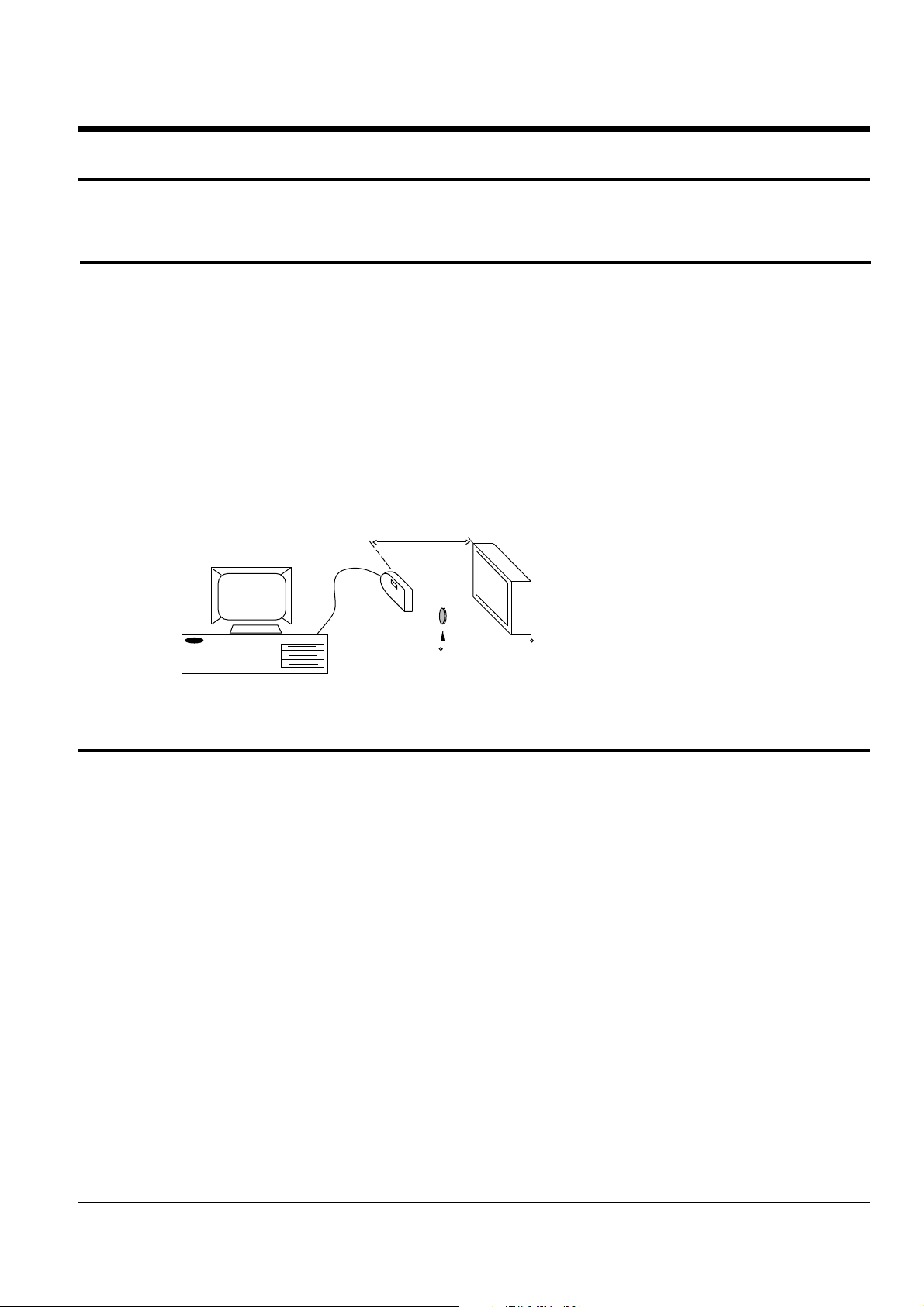
15Cm
RS-232C
PC
5100 K
< KenKo C14 49mm >
Fig. 5-1
< 3100 K DNP Light BOX >
5-2 Installing and using special softwre (on diskette)
Note: Special software handles the camera adjustment and fault diagnostics. This diskette isn't distributed to
consumers, and should be used only if a fault occurs. It allows internal disconnection state without camera
disassembly. It simulates the read, modify, and write functions of camera control value.
5-2-1 Environment
* IBM compatible
* Windows 95
* Mouse
* 256 color (or more) video card
* Hard disk (5 MByte or more)
* Supplied program diskette (3.5")
5-2-2 Functions
* DRAM test
* Flash memory test
* ASIC test
* LCD test
* Vsub value adjustment
* AWB(Auto White Balance) 3100°K ,5100°K adjustment
* Display image on PC after shot
Samsung Electronics 5-1
Alignment and Adjustments
5-2-3 Program installation
* Perform setup.exe.
* Perform SVC.exe (use directory made by setup.exe).
5-2-4 Program initial execution and adjustment
1. Initial execution
Turn on PC and execute Windows
Turn off camera
Connect PC with camera
Turn on camera
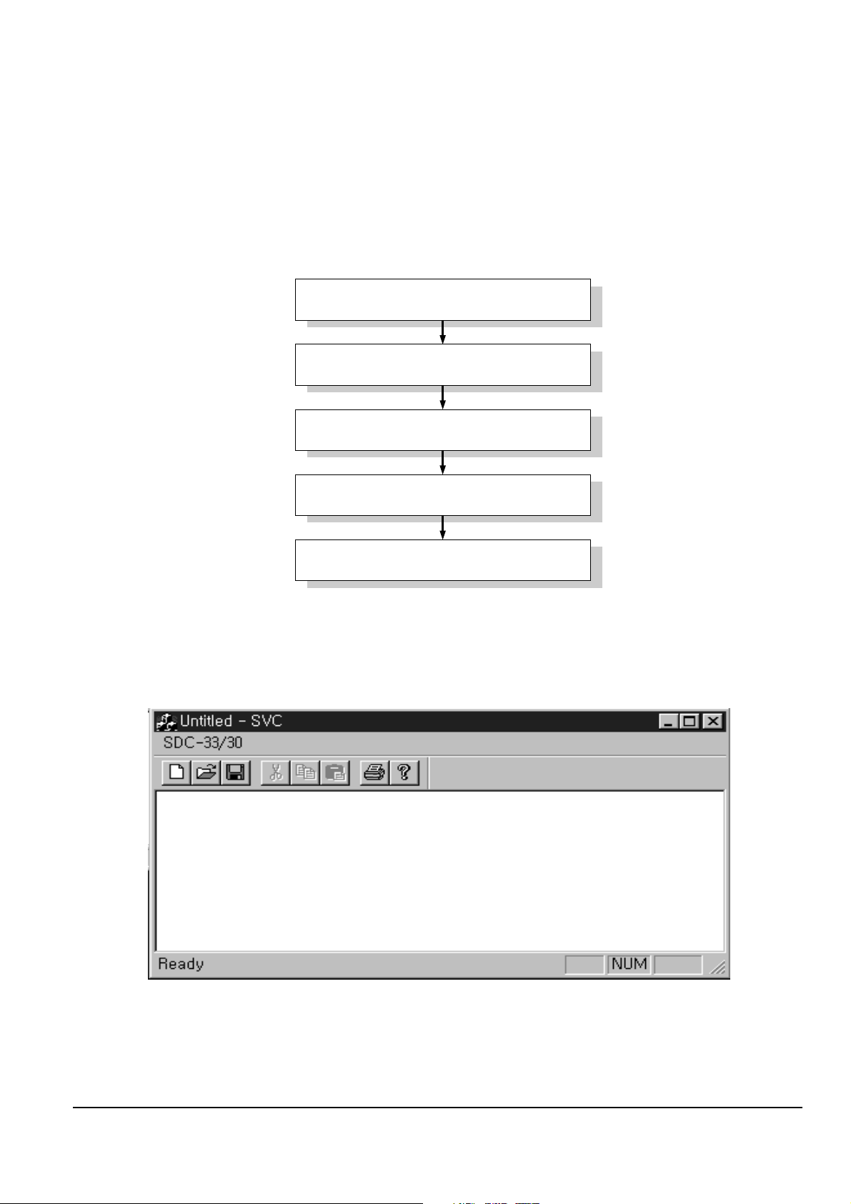
2. Initial screen of program
Execute SVC.exe in Windows
Fig.5-2
Fig. 5-3 Initial screen at execution of SVC.exe
1) The window (Fig. 5-3) appears at execution of SVC.exe.
2) It should be tested or adjusted in the following sequence.
5-2 Samsung Electronics
Select 'SDC-33/30' of Winows menu bar in
use of mouse.
Two items appear as shown in Fig. 5-5.
Select 'Option' to set the adjustment item
Select 'Start' for execution
Finish the execution
Fig. 5-4
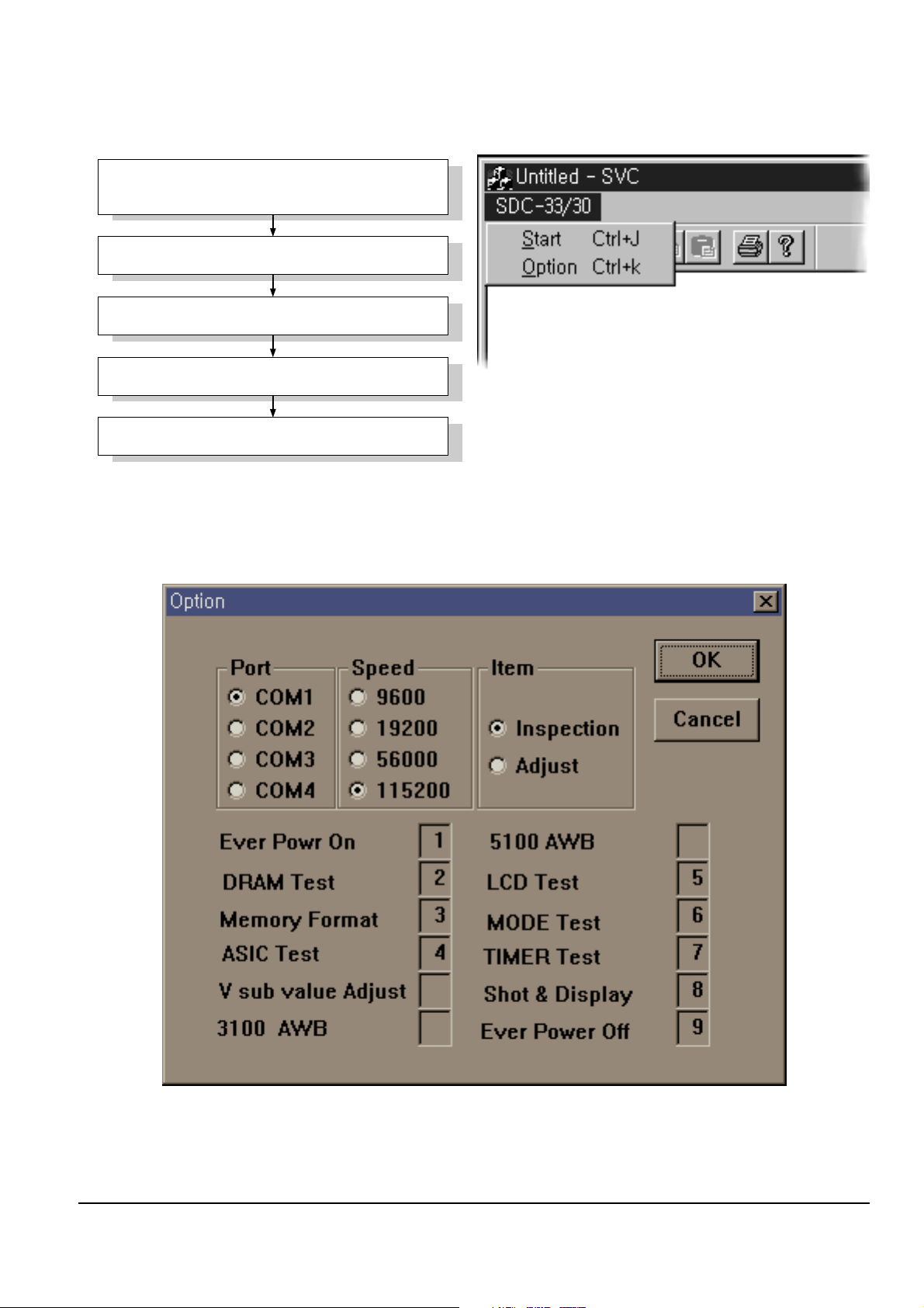
3. 'Option' window
Alignment and Adjustments
Fig. 5-5 Select 'SDC-33/30' of menu bar
1) When selecting 'Option', Fig. 5-6 is displayed.
Fig.5-6 Option Window
Samsung Electronics 5-3
Alignment and Adjustments
2) Follow this procedure when setting the options in Fig. 5-6.
Communication port setting
: Select the communication port connected with PC
: Select the communication rate between DSC and PC.
Communication rate setting
Generally 56000 is used If an error occurs during communication,
reduce the communication rate (9600 is minimum communication rate,
and 115200 is maximum).
: Test decision : Use the camera disconnection function, or change the
Adjustment setting
internal adjustment value. (Refer to Fig. 5-9)
: When the above items are set, select 'OK' and complete the adjustment
OK button
preparation.
Fig. 5-7 Option window setting
3). Adjustment execution
1) SEE Fig. 5-6. Press O.K. The screen will appear as in Fig. 5-3.
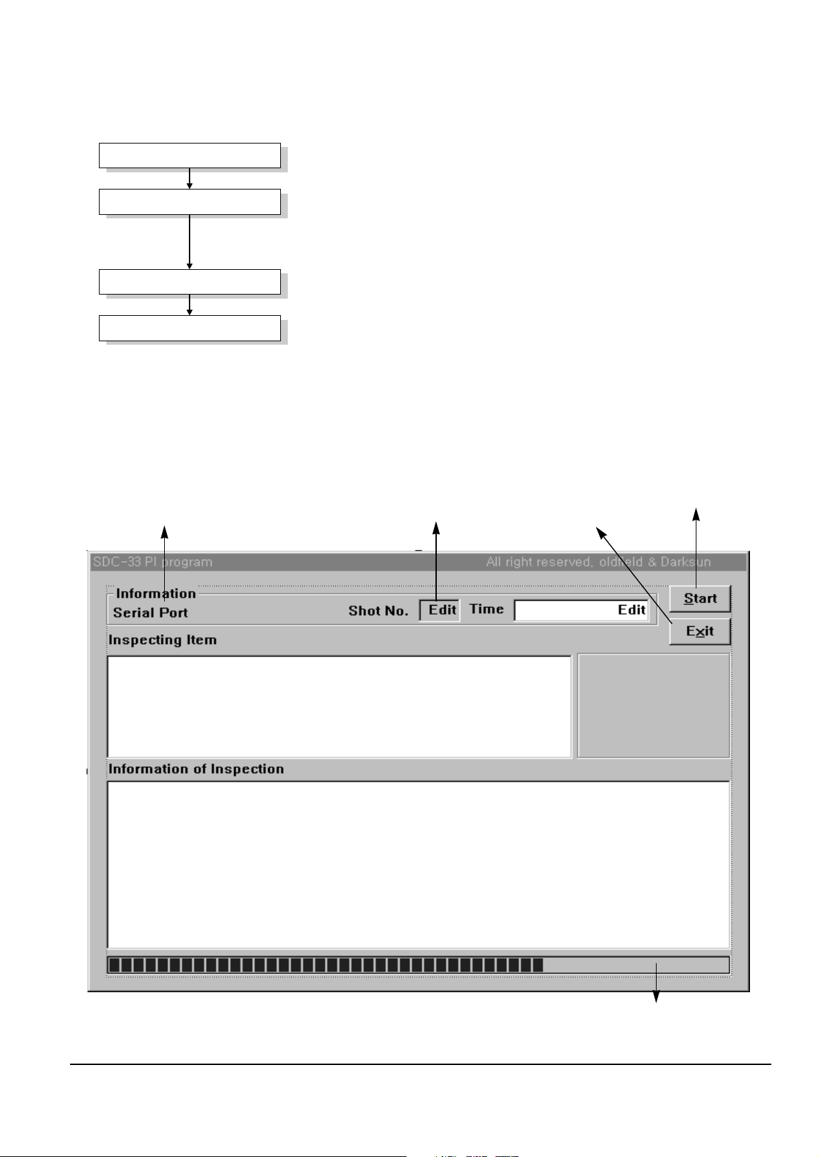
2) Select 'Start' of SVC menu to display the window shown in Fig. 5-8.
Port number of PC connected
Pictures taken
with DSC
Test/Adjustment start button
Exit
* Display screen on testing
* Display the results for test
Progress bar to display the
process state
Fig. 5-8 Execution window of test/adjustment
5-4 Samsung Electronics
 Loading...