

Page 1
Samsung Electronics 5-1
5. Adjustment
5-1. Camera Adjustment
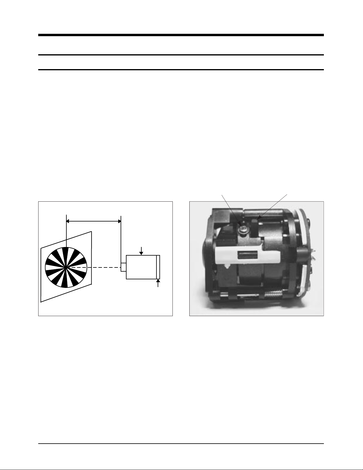
5-1-1. Focus Adjustment
¥ Adjusting in the Photo Mode
1. Aim the CCD board at the focus chart placed 2.5 meters away and perpendicular to the center of the
lens.
2. Connect the camera and TV to video output cable. Turn on the power and set to the PC mode.
3. Loose a fixing screw lightly positioned in front of a lever in the state of pulling back macro lever
toward ¡Ä (counterclockwise at the front).
4. Turn the focus adjusting lever until a lever is in focus through the TV screen (not to move the macro
lever).
5. Tighten the fixing screw when the lever is in focus.
* In the Photo mode, the state of the focus may be difficult to check because the real time is used on the
TV screen. If it isn't, you can adjust in Resume mode or with program for adjustment after taking a photograph.
¥ Adjusting with Program for Adjustment
* If the program for adjustment is used, the 3 times magnified screen allows you exactly to adjust camera.
1. Aim the CCD board at the focus chart placed 2.5 meters away and perpendicular to the center of the
lens.
2. Connect the camera to TV and PC with video output cable and PC connecting cable. Turn on the power
and set to the PC mode.
3. After running the program for adjustment on the PC to click the Focus Mode On button in the Camera
Adjustment mode.
4. Repeat step 3 through 5 of "Adjusting in the Photo Mode".
5. Click the Focus Mode On button and finish the program for adjustment.
* When adjusting the several camera, repeat step 1 through 4 after performing step 4.
(Focus Adjustment)
Focus Adjusting Lever
Fixing screw
(Lens & Lever Position)
2.5 m
LENS
FOCUS CHART
CCD BOARD
Page 2
Samsung Electronics5-2
Adjustment
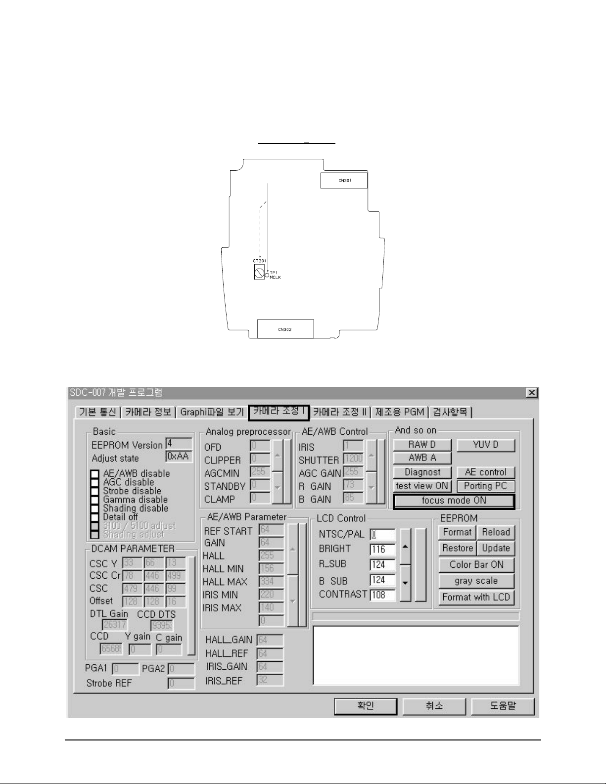
5-1-3. Program for Adjustment
5-1-2. MCLK Adjustment
1. Turn on camera power and set to Photo mode.
2. One adjustment point is TP1-MCLK. Adjust using CT301.
3. Connect probe of frequency counter with TP1.
4. Using CT301, adjust it so that MCLK is 54.00MHz+00Hz.
(External view of PCB :Main Board component side)
Page 3

Samsung Electronics 5-3
Adjustment
5-2. LCD Adjustment
5-2-1. Set up for Adjustment
5-2-2. Program for Adjustment
D ATA D ATA U P
DATA DOWN
LCD CONTROL
CONFIRM
Refer to "1-1. Camera Adjustment Program" and perform the following steps.
1. Turn off camera power and connect the camera to PC using a connecting cable.
2. Turn on the camera power and set to PC mode.
3. Run the program for adjustment on the PC and click the Camera Adjustment I button.
4. In the LCD Control option, click the Gray Scale button to display a gray scale image on the LCD monitor.
5. In the LCD Control option, click the Reload to read EEPROM Data. Click the CONFIRM button to display the EVR value.
6. Click the data in the Adjustment mode to select mode you want to adjust.
7. Refer to "5-2-3. Adjustment" to check the waveform of the adjustment point. Click the DATA UP and
DATA DOWN button to adjust.
8. After completing the adjustment, click the Update button in the EEPROM option to save the adjusted
value in EEPROM. Click the Reload button to check to make sure the EVR value is applied.
9. Click the Color Bar ON button to check the color bar of LCD monitor.
10. Close the program for adjustment.
* After performing steps 1 through 9, if you want to adjust another unit, repeat the above from step 1 to 9
but skip step 3.
Page 4

Samsung Electronics5-4
Adjustment
5-2-3. Adjustment
1. BRIGHTNESS
1) TP-VG & BRIGHT mode
2) Connect the probe of oscilloscope to TP-VG.
Press the UP/DOWN button or the number buttons so that the A
level (between pedestals) is 8.8+0.1Vp-p.
3) Using the UPDATE button, store the adjusted value in the EEPROM.
2. R-SUB BRIGHTNESS
1) TP-VR & R-SUB mode
2) Connect the probe of oscilloscope to TP-VR.
Press the UP/DOWN button or the number buttons so that the B
level (between pedestals) is 8.8¡+0.1Vp-p.
3) Using the UPDATE button, store the adjusted value in the EEPROM.
3. B-SUB BRIGHTNESS
1) TP-VB & B-SUB mode
2) Connect the probe of oscilloscope to TP-VB.
Press the UP/DOWN button or the number buttons so that the C
level (between pedestals) is 8.8¡+0.1Vp-p.
* Adjust so as to be 9.0¡+0.1Vp-p in the REV.02.
* Be sure to check the pedestal position.
3) Using the UPDATE button, store the adjusted value in the EEPROM.
4. CONTRAST
1) TP-VG & CONTRAST mode
2) Connect probe of oscilloscope to TP-VG.
Press the UP/DOWN button or the number buttons so that the D
level (between pedestals) is 2.0¡+0.1Vp-p.
3) Using the UPDATE button, store the adjusted value in the EEPROM.
(External view of PCB : LCD Board component side)
 Loading...