

Samsung SCX-8030ND Series, SCX-8040ND Series Service Manual
Service Manual
Digital Laser MFP
SCX-8030ND / 8040ND series
1. Print / Copy speed
• SCX-8030ND : 30 ppm (A4)
• SCX-8040ND : 40 ppm (A4)
2. 800 MHz CPU
3. 250GB HDD
4. 512 MB Memory (Max. 1GB)
5. 8.9 inch color graphic touch-screen LCD
6. Various option units
• 3K Booklet fi nisher, 1K Standard fi nisher
DCF, HCF, Punch unit , Multi fax etc.
The keynote of Product

ⓒ
Samsung Electronics Co.,Ltd. August. 2010
Printed in Korea.
VERSION NO.
: 0.04
CODE
: 80x0-00000E
GSPN (Global Service Partner Network)
Area Web Site
Europe,MENA, CIS,
Africa
https://gspn1.samsungcsportal.com
E.Asia, W.Asia,
China, Japan
https://gspn2.samsungcsportal.com
N.America,
S.America
https://gspn3.samsungcsportal.com

1.1 Safety Warning …………………………………………………… 1-1
1.2 Caution for safety ………………………………………………… 1-2
1.3 ESD Precautions ………………………………………………… 1-5
2.1 Specifi cations …………………………………………………… 2-1
2.2 System confi guration …………………………………………… 2-7
2.3 Sensor location …………………………………………………… 2-16
2.4 Paper handling section ………………………………………… 2-20
2.4.1 Overview……………………………………………………… 2-20
2.4.2 Components ………………………………………………… 2-23
2.4.3 Functions …………………………………………………… 2-24
2.4.4 Paper tray …………………………………………………… 2-25
2.4.5 Pick up unit …………………………………………………… 2-26
2.4.6 Registration unit …………………………………………… 2-27
2.4.7 MPF unit ……………………………………………………… 2-28
2.5 Image formation ………………………………………………… 2-29
2.5.1 Printing process overview ………………………………… 2-29
2.5.2 Imaging unit ………………………………………………… 2-30
2.6 Fuser unit ………………………………………………………… 2-34
2.6.1 Fuser unit overview ………………………………………… 2-34
2.6.2 Fuser unit components ……………………………………… 2-35
2.6.3 Fuser unit drive ……………………………………………… 2-36
2.6.4 Temperature control ………………………………………… 2-37
2.7 Laser scanning unit ……………………………………………… 2-38
2.7.1 Laser scanning unit overview ……………………………… 2-38
2.7.2 Laser scanning optical path ………………………………… 2-39
2.7.3 Laser synchronizing detectors …………………………… 2-40
2.8 Printer Drive system ……………………………………………… 2-41
chapter 1 Precautions
chapter 2 Product decription
Contents

2.8.1 Drive Motors ………………………………………………… 2-41
2.8.2 Main drive unit (OPC, DEVE, MP, REGI, DUPLEX) …… 2-43
2.8.3 Pick-up Drive ………………………………………………… 2-44
2.8.4 Fuser /Exit Drive …………………………………………… 2-45
2.8.5 Toner Duct Drive …………………………………………… 2-46
2.8.6 Drive of Toner Supply ……………………………………… 2-46
2.8.7 WTB leveling drive ………………………………………… 2-46
2.8.8 PR Release drive …………………………………………… 2-47
2.9 Scanner system ………………………………………………… 2-48
2.9.1 Scannner system overview ………………………………… 2-48
2.9.2 Scanning System components …………………………… 2-49
2.10 DADF system …………………………………………………… 2-51
2.10.1 DADF systme overview …………………………………… 2-51
2.10.2 Electric parts layout ………………………………………… 2-52
2.10.3 Description of drive system operations …………………… 2-53
2.11 Printer Electronics confi guration ……………………………… 2-59
2.11.1 Video controller …………………………………………… 2-62
2.11.2 OPE controller …………………………………………… 2-70
2.11.3 Engine controller ………………………………………… 2-74
2.11.4 Scan controller …………………………………………… 2-77
2.11.5 DADF controller …………………………………………… 2-78
2.11.6 Interface part ……………………………………………… 2-79
2.11.7 Connection part …………………………………………… 2-79
2.11.8 SMPS board ……………………………………………… 2-80
2.11.9 HVPS board ……………………………………………… 2-82
2.11.10 Eraser PBA ……………………………………………… 2-83
2.11.11 DC Power PBA …………………………………………… 2-83
2.11.12 Cassette Joint PBA ……………………………………… 2-84
2.11.13 Side Joint PBA …………………………………………… 2-84
2.11.14 Toner Connector PBA …………………………………… 2-85
2.11.15 CRUM PBA ……………………………………………… 2-86
2.11.16 Development Crum Interface PBA ……………………… 2-86
2.11.17 Deve Crum Joint PBA …………………………………… 2-87
2.11.18 Toner Curm Joint PBA …………………………………… 2-87
Contents

chapter 3 Replacement procedure
2.11.19 Fuser PBA ………………………………………………… 2-87
2.11.20 Waste Sensor PBA ……………………………………… 2-88
2.11.21 LED Panel PBA …………………………………………… 2-88
2.11.22 Scan Joint PBA …………………………………………… 2-89
2.11.23 CCDM PBA ……………………………………………… 2-90
2.11.24 Scan Cover Open Sensor PBA ………………………… 2-91
2.11.25 DADF Length Sensor PBA ……………………………… 2-91
2.11.26 DADF Width Sensor PBA ……………………………… 2-92
2.11.27 DADF Mixed Sensor PBA ……………………………… 2-92
2.11.28 DADF LED Panel PBA …………………………………… 2-93
2.11.29 Exit LED Panel PBA ……………………………………… 2-93
2.12 Heating cables ………………………………………………… 2-94
3.1 General Disassembly Procedure Precautions ………………… 3-1
3.2 Cover ……………………………………………………………… 3-2
3.2.1 Front cover …………………………………………………… 3-2
3.2.2 Left cover …………………………………………………… 3-3
3.2.3 Rear cover …………………………………………………… 3-3
3.2.4 Right cover …………………………………………………… 3-4
3.3 OPE unit …………………………………………………………… 3-5
3.4 Scan unit ………………………………………………………… 3-10
3.4.1 Scan glass …………………………………………………… 3-11
3.4.2 Scan main PBA ……………………………………………… 3-12
3.4.3 Lamp ………………………………………………………… 3-13
3.4.4 Original size detection sensor ……………………………… 3-15
3.4.5 Joint PBA …………………………………………………… 3-15
3.4.6 Joint sub PBA ……………………………………………… 3-16
3.4.7 Fan …………………………………………………………… 3-16
3.4.8 Pulley-belt …………………………………………………… 3-17
3.4.9 Scan motor and gear belt ………………………………… 3-18
Contents

3.4.10 Home sensor ……………………………………………… 3-18
3.4.11 Scanner heating cable …………………………………… 3-19
3.4.12 Align set …………………………………………………… 3-23
3.5 Fuser unit ………………………………………………………… 3-24
3.6 Side Unit …………………………………………………………… 3-35
3.6.1 Duplex sensors ……………………………………………… 3-36
3.7.2 Transfer sensors …………………………………………… 3-37
3.7.3 MP unit ……………………………………………………… 3-39
3.7 Electrical components …………………………………………… 3-44
3.7.1 Engine controller …………………………………………… 3-44
3.7.2 Hard Disk Drive (HDD) ……………………………………… 3-45
3.7.3 Video controller ……………………………………………… 3-46
3.7.4 Joint PBA …………………………………………………… 3-47
3.7.5 Toner PBA …………………………………………………… 3-47
3.7.6 Toner motor ………………………………………………… 3-48
3.7.7 DC power PBA ……………………………………………… 3-49
3.7.8 HVPS PBA …………………………………………………… 3-50
3.7.9 Lift motor …………………………………………………… 3-51
3.7.10 SMPS PBA ………………………………………………… 3-52
3.7.11 SMPS FAN ………………………………………………… 3-53
3.7.12 Ozone Filter FAN ………………………………………… 3-55
3.7.13 Side joint PBA ……………………………………………… 3-56
3.7.14 Eraser Lamp ……………………………………………… 3-57
3.7.15 Waste sensor PBA ………………………………………… 3-58
3.7.16 Temperature sensor ……………………………………… 3-58
3.8 Main drive unit …………………………………………………… 3-60
3.8.1 Main drive motor …………………………………………… 3-62
3.8.2 Main drive clutch …………………………………………… 3-62
3.9 Exit drive unit …………………………………………………… 3-63
3.10 Toner Duct drive unit …………………………………………… 3-65
3.11 PR Release drive unit ………………………………………… 3-66
3.12 Pick-up drive unit ………………………………………………… 3-67
3.13 WTB leveling drive unit ………………………………………… 3-68
3.14 LSU (Laser Scanning Unit) …………………………………… 3-71
Contents

chapter 4 Troubleshooting
Contents
3.15 Frame Duct …………………………………………………… 3-74
3.16 DADF Unit ……………………………………………………… 3-75
3.16.1 Width / Length sensor PBA ……………………………… 3-84
3.16.2 DADF Main PBA …………………………………………… 3-85
3.16.3 DADF Motors ……………………………………………… 3-87
3.16.4 DADF cover open sensor ………………………………… 3-90
3.16.5 Pick-Up Guide Sensor PBA ……………………………… 3-91
3.16.6 DADF Solenoid …………………………………………… 3-93
3.17 Exit Unit ………………………………………………………… 3-94
3.18 Regi. Unit ……………………………………………………… 3-96
3.19 Pick-Up Unit …………………………………………………… 3-98
3.20 Cassette Heating Cable ……………………………………… 3-100
4.1 Entering/Exiting Diagnostics Mode ……………………………… 4-1
4.2 Serive mode menu tree …………………………………………… 4-2
4.2.1 Information tab ……………………………………………… 4-2
4.2.2 Maintenance counts tab …………………………………… 4-4
4.2.3 Diagnostics tab …………………………………………… 4-5
4.2.4 Service Functions ………………………………………… 4-5
4.3 Information ………………………………………………………… 4-6
4.3.1 General ……………………………………………………… 4-6
4.3.2 Supply status ……………………………………………… 4-6
4.3.3 Software version …………………………………………… 4-8
4.3.4 Service Hours ……………………………………………… 4-8
4.3.5 Fault Log …………………………………………………… 4-8
4.3.5 Print reports ………………………………………………… 4-8
4.4 Maintenance Counts …………………………………………… 4-9
4.4.1 Fault count ………………………………………………… 4-9
4.4.2 Jam count …………………………………………………… 4-10
4.4.3 Part replacement count …………………………………… 4-12
4.5 Diagnotics ………………………………………………………… 4-13

Contents
4.5.1 Engine diagnostics ………………………………………… 4-13
4.5.1.1 NVM Read/Write ……………………………………… 4-13
4.5.1.2 Engine Test Routines ………………………………… 4-13
4.5.2 Fax diagnostics …………………………………………… 4-14
4.5.2.1 Fax NVM Read/Write ………………………………… 4-14
4.5.2.2 Fax Test Routines ……………………………………… 4-15
4.5.3 Scanner diagnostics ……………………………………… 4-17
4.5.3.1 Shading Test ………………………………………… 4-17
4.5.3.2 Scanner/DADF NVM Read/Write …………………… 4-17
4.5.3.3 Scanner/DADF Test Routines ……………………… 4-18
4.5.4 Adjustment ………………………………………………… 4-20
4.5.4.1 Print Adjustment ……………………………………… 4-20
4.5.4.2 Copy Adjustment ……………………………………… 4-22
4.5.4.3 Scan Area Adjustment ………………………………… 4-23
4.5.4.4 DADF Adjustment ……………………………………… 4-25
4.5.4.5 Finisher Adjustment …………………………………… 4-27
4.5.5 ACS ………………………………………………………… 4-30
4.5.6 Color Management ………………………………………… 4-31
4.6 Sevice functions ………………………………………………… 4-32
4.6.1 Main Memory Clear ………………………………………… 4-32
4.6.2 Hard Disk Maintenance …………………………………… 4-32
4.6.3 Debug Log …………………………………………………… 4-32
4.6.4 Port …………………………………………………………… 4-33
4.6.5 Capture Log ………………………………………………… 4-33
4.6.6 Toner Save ………………………………………………… 4-33
4.6.7 Count Setting of Large Page ……………………………… 4-33
4.6.8 System Recovery …………………………………………… 4-33
4.6.9 User Data Management …………………………………… 4-34
4.6.10 TR Control Mode ………………………………………… 4-35
5.1 Updating from the Printer Control Panel ……………………… 5-2
5.2 Updating from the Network …………………………………… 5-8
chapter 5 Updating Firmware

Contents
6.1 PM Supplies ……………………………………………………… 6-1
6.2. PM Procedures ………………………………………………… 6-5
6.2.1 Toner cartridge ……………………………………………… 6-5
6.2.2 Imaging unit ………………………………………………… 6-7
6.2.3 2nd Transfer roller ………………………………………… 6-11
6.2.4 Fuser Unit …………………………………………………… 6-12
6.2.5 Pick up/ Retard/ Forward roller …………………………… 6-13
6.2.6 Ozone Filter ………………………………………………… 6-13
6.2.7 DADF Rollers (Pick up /ADF/ Retard) …………………… 6-14
6.2.8 MP Pick up / Retard / Forward roller …………………… 6-19
6.2.9 Scanner Fan Filter ………………………………………… 6-21
6.3. Cleaning the PM parts ………………………………………… 6-22
6.3.1 Cleaning the charge scorotron …………………………… 6-22
6.3.2 Cleaning the pick up roller ………………………………… 6-22
6.3.3 Cleaning the Regi roller …………………………………… 6-23
6.3.4 Cleaning the tray1 feed roller ……………………………… 6-23
6.3.5 Cleaning the tray2 feed roller ……………………………… 6-24
6.3.6 Cleaning the DADF retard rubber pad …………………… 6-25
6.3.7 Cleaning the DADF rollers ………………………………… 6-26
6.3.7 Cleaning the ADF glass …………………………………… 6-27
7.1 Procedure of checking the symptoms ………………………… 7-1
7.2 Error code and troubleshooting ………………………………… 7-3
7.2.1 Error code and error message …………………………… 7-3
7.2.2 Error Code Details ………………………………………… 7-11
7.3 Image quality problems and solutions ………………………… 7-101
7.3.1 Vertical Lines ………………………………………………… 7-102
7.3.2 Horizontal Lines ……………………………………………… 7-103
7.3.3 White spot …………………………………………………… 7-104
7.3.4 Black background ………………………………………… 7-105
7.3.5 Blurred image ……………………………………………… 7-106
chapter 6 Preventive Maintenance (PM)
chapter 7 Troubleshooting

Contents
7.3.6 Uneven pitch and jitter image ……………………………… 7-107
7.3.7 Skewed image ……………………………………………… 7-108
7.3.8 Low image density ………………………………………… 7-109
7.3.9 Blank copy, Black copys …………………………………… 7-110
7.3.10 Uneven density in sub scan direction …………………… 7-112
7.3.11 Uneven density in main scan direction ………………… 7-113
7.3.12 Poor fusing performance ………………………………… 7-114
7.3.13 Stain on the paper back side …………………………… 7-115
7.3.14 DADF skew testing ……………………………………… 7-116
7.4 Other Errors ……………………………………………………… 7-121
8.1 Engine 1 …………………………………………………………… 8-1
8.2 Engine 2 …………………………………………………………… 8-2
8.3 Main board & OPE ……………………………………………… 8-3
8.4 Scan & DADF …………………………………………………… 8-4
8.5 Bottle joint board & side joint board …………………………… 8-5
8.6 DC control board ………………………………………………… 8-6
8.7 Cassette joint board & Drive joint board ……………………… 8-7
8.8 Heater & Fuse …………………………………………………… 8-8
9.1 Entry Point ………………………………………………………… 9-1
9.2 USB ………………………………………………………………… 9-2
9.3 Network …………………………………………………………… 9-4
9.4 Confi rmation Page ……………………………………………… 9-5
9.5 Error Page ………………………………………………………… 9-6
9.6 Progress Page …………………………………………………… 9-7
9.7 Error List …………………………………………………………… 9-8
9.8 HDD Repair ……………………………………………………… 9-8
9.9 HDD Failure ……………………………………………………… 9-10
chapter 9 System Recovery
chapter 8 System Diagram

Contents
10.1 Tools for troubleshooting ……………………………………… 10-1
10.2 Abbreviations …………………………………………………… 10-4
chapter 10
Reference Information
1. Prec
a
1. Warning and cautio
n
In order to prevent accidents and to prevent damage t
o
below carefully before servicing the printer and follow
(1) Only to be serviced by appropriately qualified servi
High voltages and lasers inside this product are da
qualified service technician.
1.1 Safety Warning
(2) Use only Samsung replacement parts
.
There are no user serviceable parts inside the prin
t
additions to the printer as these could cause the pr
fire hazards.
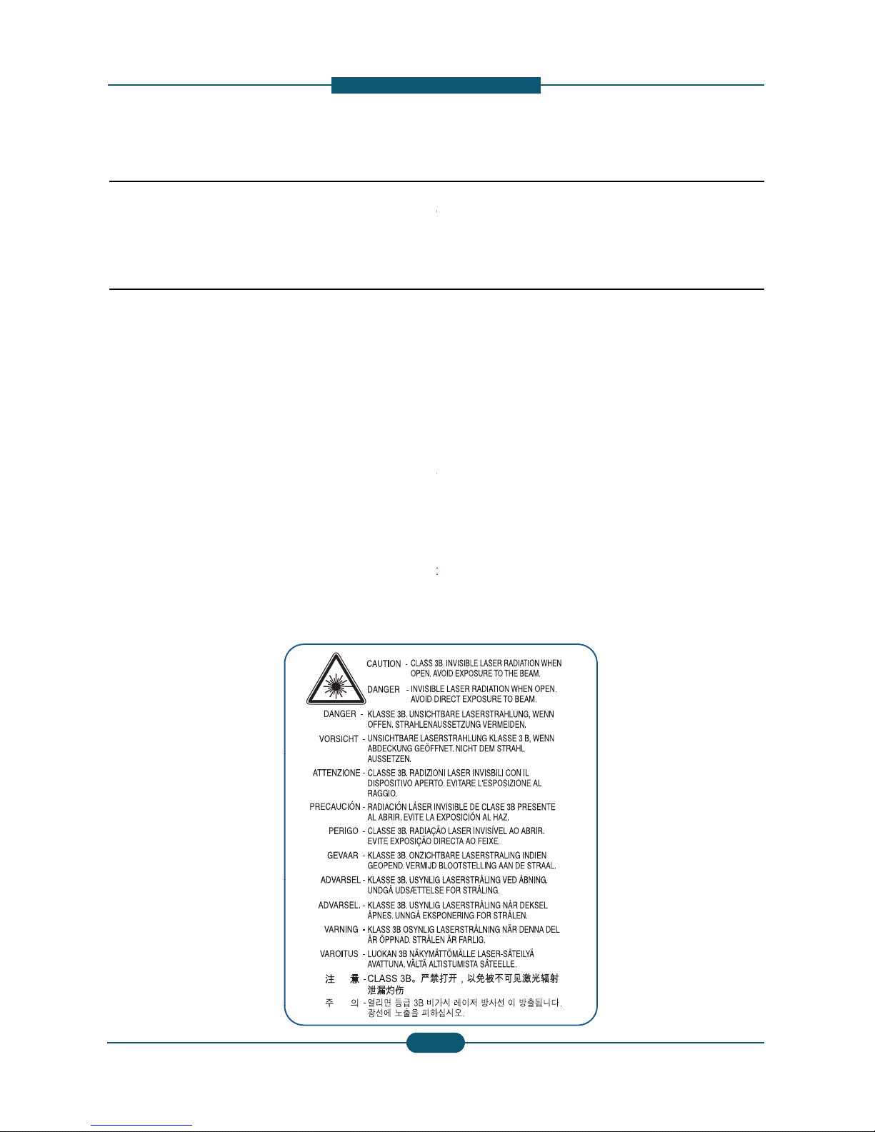
(3) Laser Safety Statement
The Printer is certified in the U.S. to conform to th
e
Subchapter J for Class 1(1) laser products, and el
s
f
orming to the requirements of
IEC 825. Cl
ass I las
laser system and printer are designed so there is n
Class I level during normal operation, user mainte
n
Warning >> Never operate or service the printer with
t
assembly. The reflected beam, although invisible, can
When using this product, these basic safety pre-cauti
o
electric shock, and personal injury.
Service Manual
SCX-8030/8040 series
1
-
utions
for s afety
o
the equipment please read the precautions listed
them closely.
ce technician.
ngerous. This printer should only be serviced by a
er. Do not make any unauthorized changes or
inter to malfunction and create an electric shock or
requirements of DHHS 21 CFR, chap te r 1
ewhere, it is certified as a Class I laser product coner products are not considered to be hazardous. The
ever any human access to laser radiation above a
ance, or prescribed service condition.
he protective cover removed from Laser Scanner
damage your eyes.
ns should always be followed to reduce risk of fire,
SAMSUNG ELECTRONICS
Version 0.05
1

1. Prec
a
1.2 Caution for safety
1.2.1 Toxic material
This product contains toxic materials that could cause
i
(1) If the LCD control panel is damaged it is possible f
o
with the skin should be avoided. Wash any splash
e
doctor. If the liquid gets into the mouth or is swallo
w
(2) Please keep Drum cartridge and Toner cartridge a
w
Drum cartridge and Toner Cartridge may be harmf
u
1.2.2 Electric shock and fire safety
p
Failure to follow the following instructions could cause
e
(1) Use only the correct voltage, failure to do so could
d
electric shock.
(2)
Use only the power cable supplied with the printer.
() y p pp p
cable to overheat and potentially cause a fire.
(3) Do not overload the power socket, this could lead t
o
lead to a fire.
(4) Do not allow water or other liquids to spill into the p
paper clips, pins or other foreign objects to fall into
to an electric shock or fire hazard.
(5)
Never touch the plugs on either end of the power c
a
() p g p
When servicing the printer remove the power plug
f
(6) Use caution when inserting or removing the power
c
firmly and pull. The power connector must be inser
t
overheating possibly leading to a fire.
(7) Take care of the power cable. Do not allow it to be
c
damaged. Do not place objects on top of the powe
r
overheat and cause a fire. Exposed cables could c
a
cable immediately, do not reuse or repair the dama
the power cable, weakening the cover or exposing
(8) Ensure that the power sockets and plugs are not cr
a
should be repaired immediately. Take care not to c
the machine.
(9) Use caution during thunder or lightning storms. Sa
m
from the power source when such weather conditi
o
p
ower cord if it is still connected to the wall socket
i
p
(10) Avoid damp or dusty areas, install the printer in a
c
machine near a humidifier or in front of an air con
d
can lead to overheating and cause a fire or cause
(11) Do not position the printer in direct sunlight. This
w
possibly leading to the printer failing to work prop
e
(12) Do not insert any metal objects into the machine t
h
could make contact with a high voltage conductor
Service Manual
SCX-8030/8040 series
1
-
utions
llness if ingested.
r the liquid inside to leak. This liquid is toxic. Contac
t
s from eyes or skin immediately and contact your
ed see a doctor immediately.
ay from children. The toner powder contained in the
l and if swallowed you should contact a doctor.
recautions
lectric shock or potentially cause a fire.
amage the printer and potentially cause a fire or
Use of an incorrectl
y sp
ecified cable could cause the
yp
overheating of the cables inside the wall and could
rinter, this can cause electric shock. Do not allow
the printer these could cause a short circuit leading
ble with wet hands, this can cause electric shock.
rom the wall socket.
onnector. When removing the power connector, grip it
ed completely, otherwise a poor contact could cause
ome twisted, bent sharply around corners or wise
cable. If the power cable is damaged it could
use an electric shock. Replace the damaged power
cable. Some chemicals can attack the coating on
cables causing fire and shock risks.
cked or broken in any way. Any such defects
ut or damage the power cable or plugs when moving
sung recommends that this machine be disconnected
ns are expected. Do not touch the machine or the
n these weather conditions.
lean well ventilated location. Do not position the
itioner. Moisture and dust built up inside the machine
parts to rust.
ill cause the temperature inside the printer to rise
rly and in extreme conditions could lead to a fire.
rough the ventilator fan or other part of the casing, it
inside the machine and cause an electric shock.
SAMSUNG ELECTRONICS
Version 0.05
2

1. Prec
a
1.2.3 Handling Precautions
The following instructions are for your own personal s
a
product.
(1) Ensure the printer is installed on a level surface, ca
cause the printer to tip or fall.
(2) The printer contains many rollers, gears and fans.
fingers, hair or clothing in any of these rotating de
v
(3) Do not place any small metal objects, containers
o
which if spilled could get into the machine and ca
u
(4) Do not install the machine in areas with high dust
o
a humidifier or heater. Damage could be caused t
o
1.2.4 Assembly / Disassembly Preca
u
g
(5) Do not place candles, burning cigarettes, etc on th
(6) When reinstalling the imaging unit or ITB unit at p
o
Replace parts carefully and always use Samsung par
t
cable routing before dismantling any part of the machi
Please carry out the following procedures before dism
(1) Check the contents of the machine memory and m
if the main board or network card is replaced.
(2) Ensure that power is disconnected before servicin
g
(3) Disconnect printer interface cables and power cabl
(4) Only use approved spare parts. Ensure that part n
u
temperature rating are correct.
(5) When removing or re-fitting any parts do not use e
x
plastic.
(6) Take care not to drop any small parts into the mac
(7) Handling of the OPC Drum
-
The OPC Drum can be irreparably damaged if it e
Take care not to expose the OPC Drum either to
d
room lighting. Exposure for as little as 5 minutes
c
properties and will result in print quality degradati
o
Remove the OPC Drum and store it in a black ba
g
working with the Covers (especially the top cover
)
damage the OPC Drum.
- Take care not to scratch the green surface of OP
C
If the green surface of the Drum Cartridge is scra
t
compromised.
Service Manual
SCX-8030/8040 series
1-1
-
utions
fety, to avoid injury and so as not to damage the
of
supporting its weight. Failure to do so could
Take great care to ensure that you do not catch your
ices.
f water, chemicals or other liquids close to the printer
se damage, shock or fire hazard.
r moisture levels, beside on open window or close to
the printer in such areas.
tions
p
e printer, These could cause a fire.
wer off, perform the OPC-ACR surely.
s. Take care to note the exact location of parts and
ne. Ensure all parts and cables are replaced correctly.
antling the printer or replacing any parts.
ake a note of any user settings. These will be erased
or replacing any electrical parts.
.
mber, product name, voltage, current and
cessive force, especially when fitting screws into
hine.
to
light
.
irect sunlight or to fluorescent or incandescent
an damage the surface of the photoconductive
n. Take extra care when servicing the printer.
or other lightproof container. Take care when
open as light is admitted to the OPC area and can
Drum Unit.
ched or touched the print quality will be
SAMSUNG ELECTRONICS
Version 0.05
3
3

1. Prec
a
1.2.5 Disregarding this warning may
(1) Be careful with high temperature componen ts.
The fuser unit works at a high temperature. Use ca
u
cool down before disassembly.
(2) Do not put fingers or hair into the rotating parts.
When operating a printer, keep your hands and hai
r
motor, fan, etc.).
(3) When moving the printer :
- When transporting/installing the equipment, employ f
o
- Be sure not to hold the movable parts or units (e.g. th
equipment.
- Be sure to use a dedicated outlet with 110V/220V po
w
- The equipment must be grounded for safety.
- Select a suitable place for installation. Avoid excessi
v
sunlight.
- Provide proper ventilation since the equipment emits
- The e
quip
ment must be installed near the socket outl
qp
-Be sure to fix and plug in the power cable securely aft
e
-If you are moving the machine a short distance, you s
h
(e.g : same building through elevator)
- If you are moving the machine a long distance, you
s
& staple unit, tape and disassemble all trays. (e.g : m
o
Service Manual
SCX-8030/8040 series
1
-
utions
cause bodily injury
tion when working on the printer. Wait for the fuser to
away form the rotating parts (Paper feeding entrance,
ur people and be sure to hold the lifting handles.
e control panel, DADF) when transporting the
er input.
e heat, high humidity, dust, vibration and direct
a slight amount of ozone.
et and must be accessible.
e
r the installation so that no one trips over it.
ould separate the finisher.
hould remove toner & imaging unit, lock scan carrier
ved by truck or so)
SAMSUNG ELECTRONICS
Version 0.05
4

1. Prec
a
1.3 ESD Precautions
Certain semiconductor devices can be easily damage
d
commonly called “Electrostatically Sensitive (ES) Dev
integrated circuits, some field effect transistors, and se
The techniques outlined below should be followed to
h
caused by static electricity.
Caution >>Be sure no power is applied to the chassis
1. Immediately before handling a semiconductor com
p
off any electrostatic charge on your body by touchi
n
commercially available wrist strap device, which sh
o
prior to applying power to the unit unde r test.
2. After removing an electrical assembly equipped wit
h
such as aluminum or copper foil, or conductive foa
m
vicinity of the assembly.
3. Use only a grounded tip soldering iron to solder or
d
“
”
4. Use only an anti
-
static solder removal device. Som
static” can generate electrical charges sufficient to
5. Do not use Freon-propelled chemicals. When spra
y
damage ESDs.
6. Do not remove a replacement ESD from its protecti
v
Most replacement ESDs are packaged with all lead
s
or a comparable conductive material.
7. Immediately before removing the protective shortin
g
touch the protective material to the chassis or circui
8. Maintain continuous electrical contact between the
E
until completely plugged or soldered into the circuit.
9. Minimize bodily motions when handling unpackage
d
the brushing together of clothing fabric and lifting o
n
electricity sufficient to damage an ESD
.
Service Manual
SCX-8030/8040 series
1
-
utions
by static electricity. Such components are
ices” or ESDs. Examples of typical ESDs are:
“”
chip components
.
elp reduce the incidence of component damage
or circuit, and observe all other safety precautions.
onent or semiconductor-equipped assembly, drain
g a known earth ground. Alternatively, employ a
uld be removed for your personal safety reasons
ESDs, place the assembly on a conductive surface,
, to prevent electrostatic charge buildup in the
esolder ESDs.
“
solder removal devices not classified as anti
-
damage ESDs.
ed, these can generate electrical charges sufficient to
v
e packaging until immediately before installing it.
s
shorted together by conductive foam, aluminum foil,
material from the leads of a replacement ESD,
t assembly into which the device will be installed.
SD and the assembly into which it will be installed,
replacement ESDs. Normal motions, such as
e’s foot from a carpeted floor, can generate static
SAMSUNG ELECTRONICS
Version 0.05
5

2. Product
D
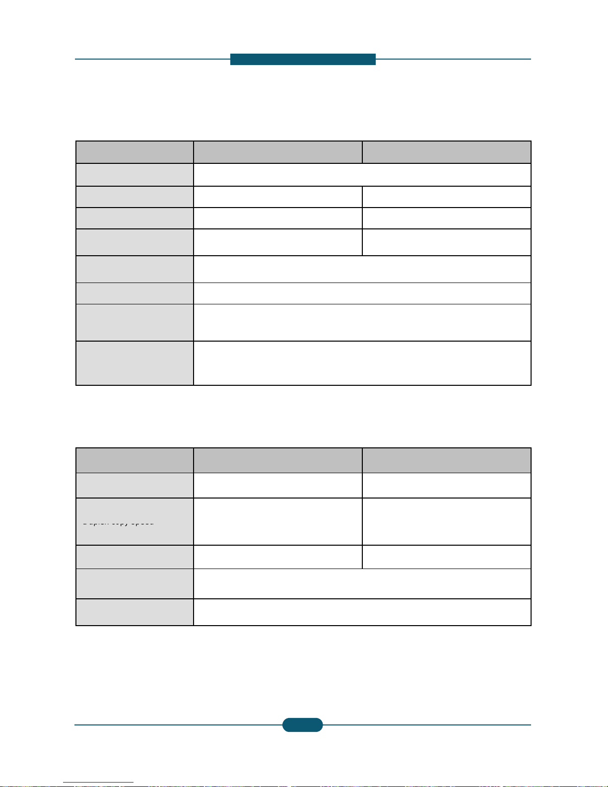
2.1 Specifications
2. Product description
Item SCX-8030ND
Printing Speed (A4) 30 ppm
FCOT < 7 sec
General Specifications
Warm-up Time < 25 sec
Duplex Printing Speed 30 ppm
Scanning Speed (A4) (Color)
40 ipm @ 600 dpi
60 ipm @ 300 dpi
Memory 512MB (Max.1GB )
HDD 250GB
CPU SPGPv4 800MHz
Resolution
• Optical : 600 x 600 d
• Enhanced : Draft 60
0
Default
6
Up to 6
0
Gradation 256
Size (W x D x H ) 677.5 x 742.8 x 924 m
Weight Approx. 113Kg (250lb
)
Noise (dB)
• Ready mode : 37 d
B
• Printing mode : 54 d
B
• Copying mode : 57 d
Power consumption
• Average operating
m
• Ready mode : Less t
• Low Power mode : L
e
• Power Save mode :
L
• Power off mode : 0
W
Power requirement
AC 110-127V , 50/60
H
Note - See the Rating
(hertz) and type of cur
Power output rating for heating
wire in DCF/HCF
AC 110-127V , 50/60
H
Note - See the Rating
and type of current.
Service Manual
SCX-8030/8040 series
2
-
The voltage rating of
h
escription
SCX-8040ND
40 ppm
< 5.5 sec
40 ppm
pi
x 600 x 1bit
00 x 600 x 2 bit
0 x 600 x 4 bit
m (26.7 x 29.2 x 36.4 inches)
(Including consumables and tray)
(A)
(A)
B(A)
ode : Less than 1,100 W
han 250 W
ss than 40 W
ess than 7 W
z or AC 220-240V , 50/60 Hz
label on the machine for the correct voltage, frequency
rent.
z or AC 220-240V , 50/60 Hz
label on the machine for correct voltage, frequency (hertz)
SAMSUNG ELECTRONICS
Version 0.05
1
eating wire is the same as the machine’s voltage rating.
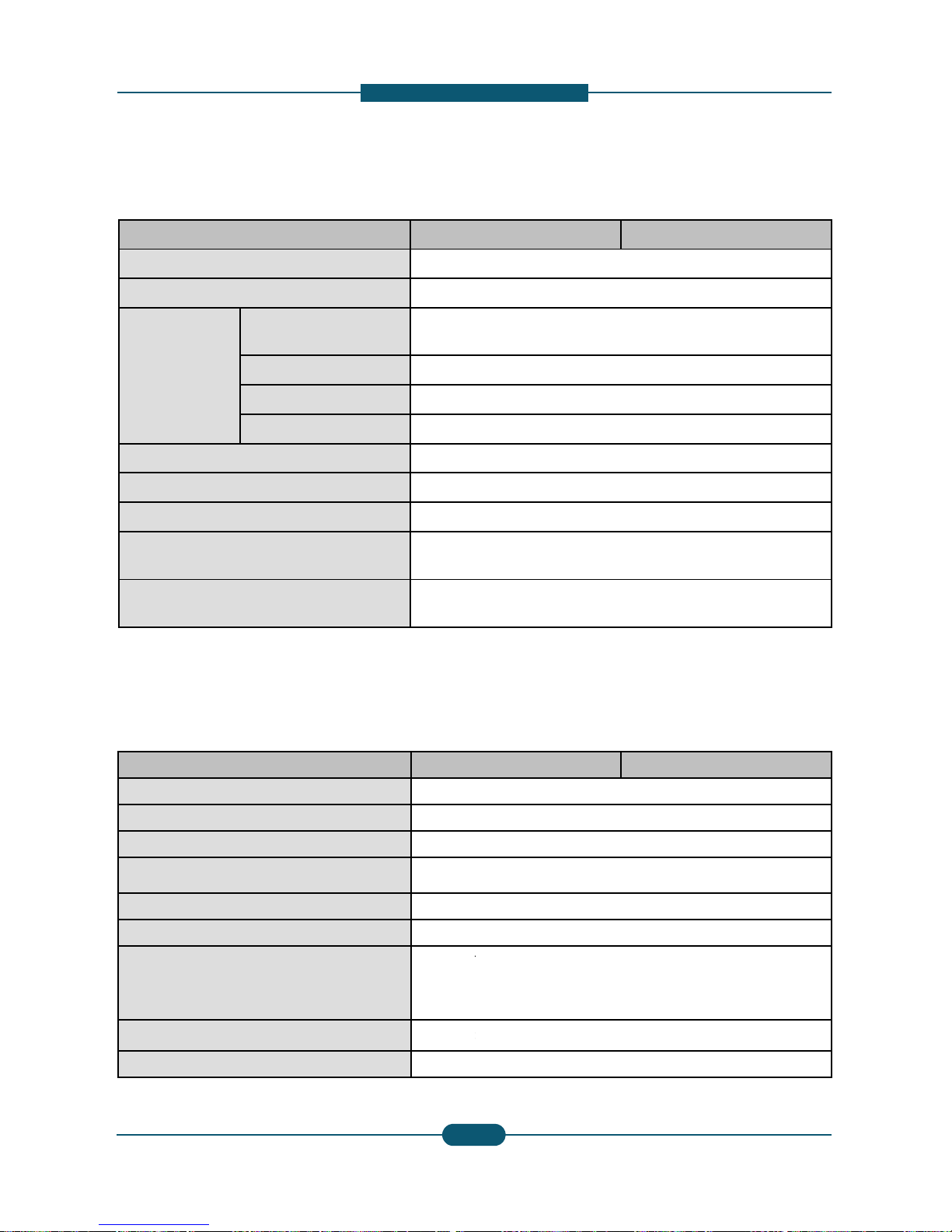
2. Product
D
Item SCX-8030ND
Printer Specifications
Printing method
laser beam printing
Printing speed Up to 30 ppm (A4), 30 ppm
Duplex printing speed Up to 30 ipm (A4), 30 ipm (
L
First print out time
(from ready)
< 9 sec
Print resolution
•Default : Up to 2,
400
x
600
• Max : Up to 9,600 x 600 d
p
Printer language PCL5e, PCL6, PostScript 3,
OS compatibility
• Windows: 2000 ,XP,2003 ,
• Various Linux OS
• Macintosh: Mac OS X 10.
5
Interface
• High speed USB 2.0
• Ethernet 10/100/1000 Bas
e
• FDI (optional)
Copier specifications
Item SCX-8030ND
Copy Speed Up to 30 cpm (A4), 30 cpm
Simplex to Duplex (1-1,1-2)
: Up to 30 ipm in A4 (30 ipm
Duplex copy speed
Dupl
ex to Duplex (2-1.2-
2)
: Up to 18 ipm in A4 (18 ipm
First copy out time < 7 sec
Copy resolution
• Platen : 600 x 600 dpi
• Document feeder: Up to 6
0
• Platen : 25% to 400%
Zoom range
• Document feeder: 25% to
4
Service Manual
SCX-8030/8040 series
2
-
escription
SCX-8040ND
(Letter) Up to 40 ppm (A4), 40 ppm (Letter)
etter) Up to 40 ipm (A4), 40 ipm (Letter)
< 8 sec
dpi effective outpu
t(600x600x2 dpi)
i effective output(600x600x2 dpi)
PDF 1.7+, TIFF, PJL
Vista ,2008 ,Win7
~10.6
TX (embedded type)
SCX-8040ND
(Letter) Up to 40 cpm (A4), 40 cpm (Letter)
in Letter)
Simplex to Duplex (1-1,1-2)
: Up to 40 ipm in A4 (40 ipm in Letter)
in Letter)
Dupl
ex to Duplex (2-1.2-
2)
: Up to 24 ipm in A4 (24 ipm in Letter)
< 5.5 sec
0 x 600 dpi
00%
SAMSUNG ELECTRONICS
Version 0.05
2
2. Product
D
Item SCX-803
0
Compatibility TWAIN s
t
Scanner specifications
Scanning method Color CC
Resolution
TWAIN standard
Up to 60
0
(Up to 4,
8
Scan to USB 100, 200,
Scan to Email 100, 200,
Scan to Server 100, 200,
Network Scan File format PDF, TIF
Effective scanning length Max. 432
Effective scanning width Max. 297
Color bit depth
Internal: 3
External:
Mono bit depth
1 bit for li
n
8 bit for g
Item SCX-803
0
Compatibility Super G
3
Fax Specifications
Applicable line
Public Sw
Data coding MH/MR/
M
Modem speed 33.6kbps
Transmission speed Up to 3 s
e
Maximum document length 432 mm
(
Resolution
• Standar
• Fine : 2
0
• Super
F
• Ultra Fi
n
Memory HDD Ba
c
Auto dialer up to 500
Service Manual
SCX-8030/8040 series
2
-
escription
ND SCX-8040ND
andard (network)
D
x 600 dpi
00 x 4,800 dpi by software enhancement)
300, 400, 600 dpi
300, 400, 600 dpi
300, 400, 600 dpi
F, JPEG
mm (17 inches)
mm (11.7 inches)
bit
24 bit
eart & halftone
ray scale
ND SCX-8040ND
Telephone Network (PSTN) or behind PABX
MR/JBIG/JPEG
conds/page
17 inches)
:
203 x 98 dpi
3 x 196 dpi
ine : 300 x 300 dpi
e : 600 x 600 dpi
kup
numbers
SAMSUNG ELECTRONICS
Version 0.05
3
2. Product
D
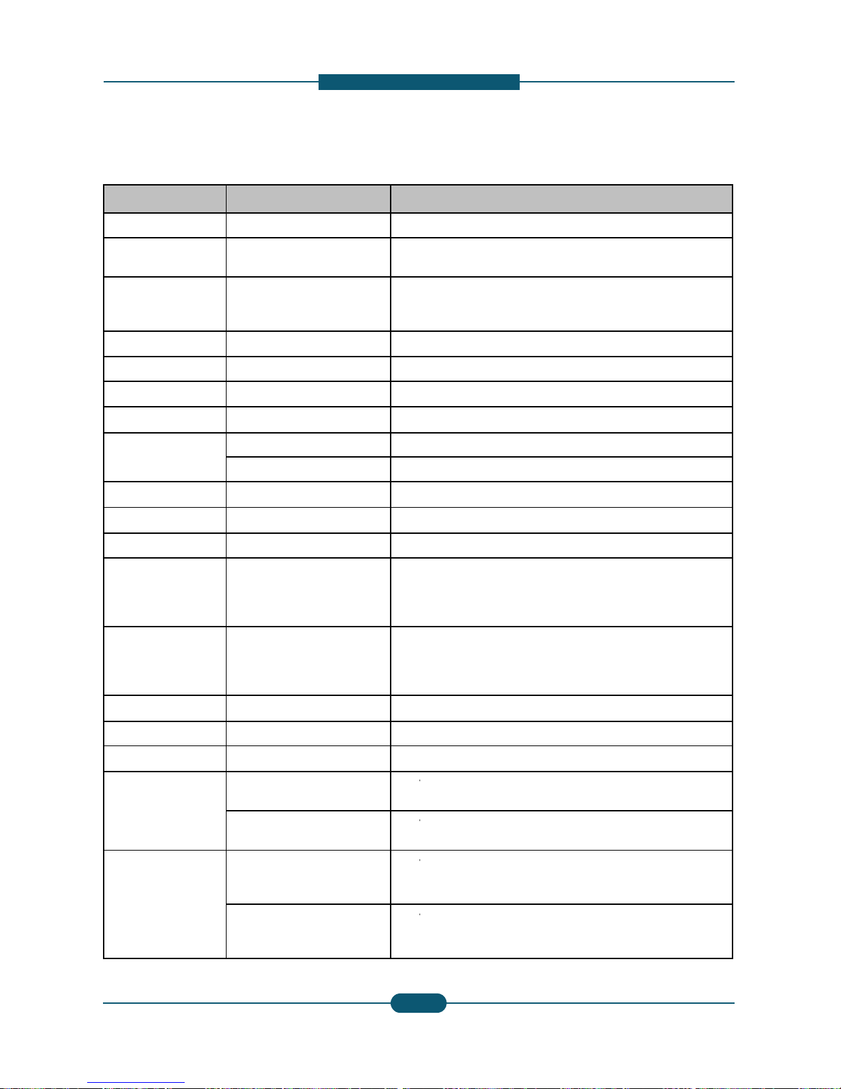
Paper Specifications
Item SCX-8030ND
Input Paper Capacity
• Standard : 1,040 (Cassett
e
• Maximum : 1,040 (Cassett
e
Note – The SCX-8025ND n
o
Output Paper Capacity
• Standard : 500 (Center Ou
• Maximum : 3,250 (Booklet
Paper Size
• Cassette :
148 x 210 m
m
•MP Tray :
98 x 148 mm(
3
• High Capacity Feeder :
A
4
Paper Type
•
C
assette :
Plain Pap
er,
Th
Recycled, Lett
e
• MP Tray :
Plain Pa
p
er, T
h
Recycled, Lett
e
Transparency,
• High Capacity Feeder :
Pl
aPre
Paper Weight
• Cassette : 60 ~ 163 gsm (
1
• MP Tray : 60 ~ 216 gsm (1
• High Capacity F eeder : 60
Original Capacity for DADF 100 sheets
Original Size for DADF
• Full supported Size : 140
X
• Auto-detected Size : A3, B
Product Model name Life **
Consumables
Original Weight for DADF
• Simplex : 42 ~ 163 gsm (3
0
• Duplex : 50 ~ 128 gsm (30
Toner Cartridge
MLT-K606S 35K pa
g
MLT-K607S 20K pa
g
Imaging unit MLT-R607K 100K p
a
Waste Toner Container MLT-W606 300K p
a
* American 35K Toner can be used for SCX-8030N
D
** Declared yield value in accordan ce with 6% cover
a
Service Manual
SCX-8030/8040 series
2
-
escription
SCX-8040ND
1 & 2) + 100 (MP Tray)
1 & 2) + 2,000 (High Capacity Feeder) + 100 (MP Tray)
t supports the Tray(DCF,HCF) and the Finishe
r
tput Tray)
Finisher) + 125 (Job Separator)
(5.83”x 8.27”) ~ 305 x 457 mm (12”x 18”)
.8”x 5.8”) ~ 305 x 1200 mm (12”47”)
/ Letter
n Paper,
Thick Pap
er, Bond, Punched, Pre-Printed,
rhead, Cotton, Colored, Archive, CardStock, Label
in Paper, Thick Paper, Bond, Punched, Pre-Printed,
rhead, Cotton, Colored, Archive, CardStock, Label,
Envelope
in Paper, Thin Paper, Thick Paper, Bond, Punched,
-Printed, Recycled, Cotton, Colored, CardStock
6lb Bond ~ 90lb Index)
6lb Bond ~ 90lb Cover)
~ 163 gsm (16lb Bond ~ 90lb Index)
140mm ~ 297 x 432mm (5.5" x 5.5" ~ A3/Ledger)
4, B4 SEF, A4, A4 SEF, B5, B5 SEF, A5, A5 SEF
SCX-8030ND SCX-8040ND
lb Book ~ 90lb Index)
lb Book ~ 34lb Bond)
es X* O
es O O
ges O O
ges O O
ge.
SAMSUNG ELECTRONICS
Version 0.05
4
2. Product
D
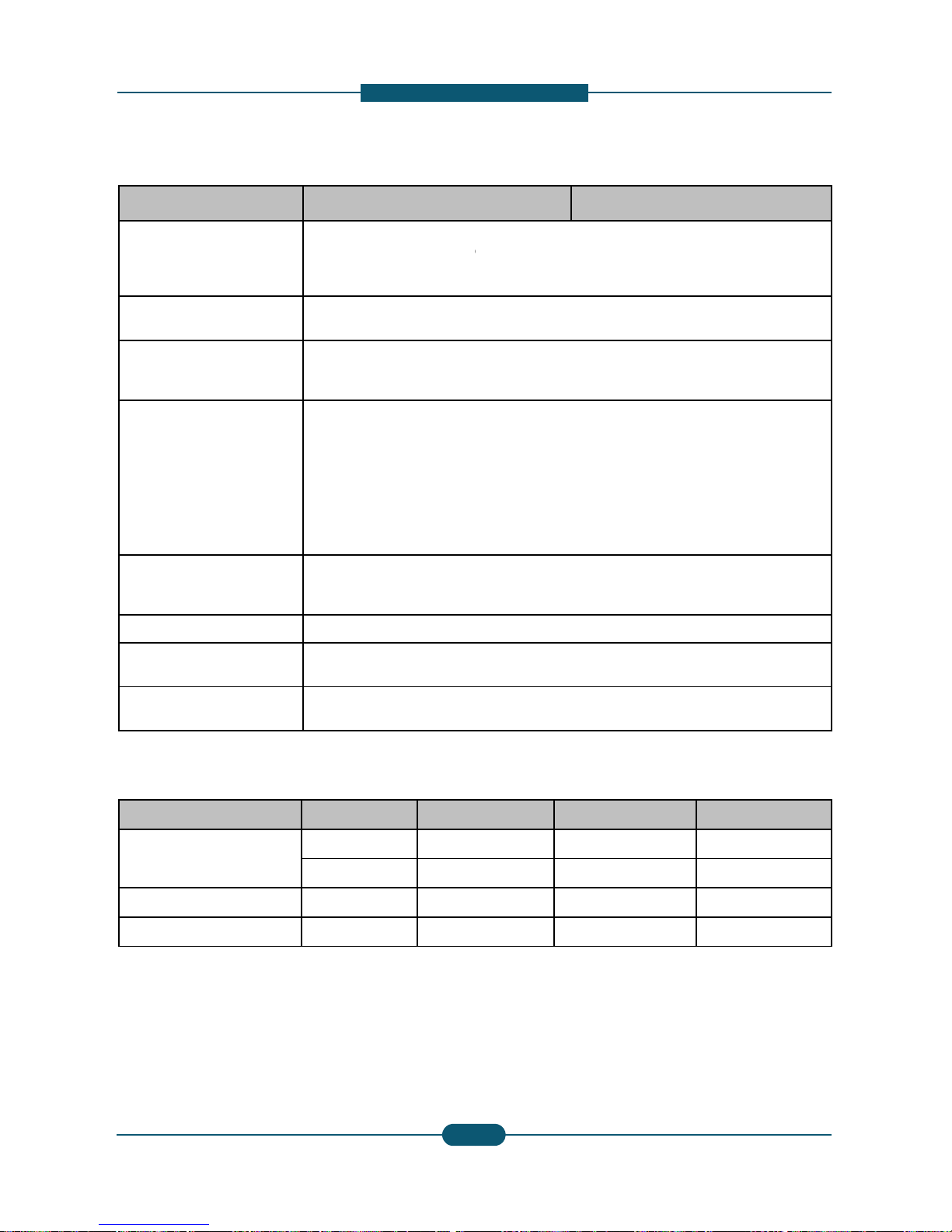
Option Unit Model name Re
m
Stand CLX-DSK10T/SEE
Option Unit
Dual Cassette
Feeder
CLX-PFP000/SEE 520
HCF
(High Capacity
Feeder)
CLX-HCF102/SEE
CLX-HCF102/XAA
2,0
0
Job Separator SCX-JST000/SEE 125
Bridge Unit CLX-BRG200/SEE
Standard Finisher CLX-FIN40S/SEE 1,2
5
Booklet Finisher CLX-FIN40L/SEE 3,2
5
Punch Kit
CLX-HPU000/XAA 2-3
CLX-HPU001/SEE 2-4
Working Table CLX-WKT000/SEE
512MB Memory SCX-MEM300/SEE 512
FDI Kit CLX-KIT10F/SEE Seri
Fax Kit
CLX-FAX150/SEE
CLX-FAX150/XEE
CLX-FAX150/XEG
G3,
CLX-FAX150/XEU
Fax Multiline Kit
CLX-FAX250/SEE
CLX-FAX250/XEE
CLX-FAX250/XEG
CLX-FAX250/XEU
G3
SmarThru Workflow Do
c
CounThru Co
u
Advanced Scan Kit CLX-KIT10D/SEE Se
a
Heating wire for
Cassette, HCF,
DCF
CLX-DHK11C
110
V
of
H
CLX-DHK12C
220
V
of
H
Heating wire for
Scan
CLX-DHK11S
110
V
volt
a
volt
a
CLX-DHK12S
220
V
volt
a
volt
a
Service Manual
SCX-8030/8040 series
2
-
escription
ark
Sheet Tray x 2
0 Sheets (LTR, A4)
Pages
0 Stacking, Stapling (5 Pos)
0 Stacking, Stapling (5 Pos), Booklet
Holes (NA)
Holes (EU)
MB
al Port
T.37/38, PC Fax SW, Fax Manual Softcopy
ument Distribution Solution
nter/cost Management Solution
rchable PDF, Barcode, etc.
, 10W (equipped by service person at field, voltage rating
eating Wire is the same as the machine’s voltage rating)
, 10W (equipped by service person at field, voltage rating
eating Wire is the same as the machine’s voltage rating)
, 5W and 10W (equipped by service person at field,
ge rating of Heating Wire is the same as the machine’s
ge rating)
, 5W and 10W (equipped by service person at field,
ge rating of Heating Wire is the same as the machine’s
ge rating)
SAMSUNG ELECTRONICS
Version 0.05
5
2. Product
D
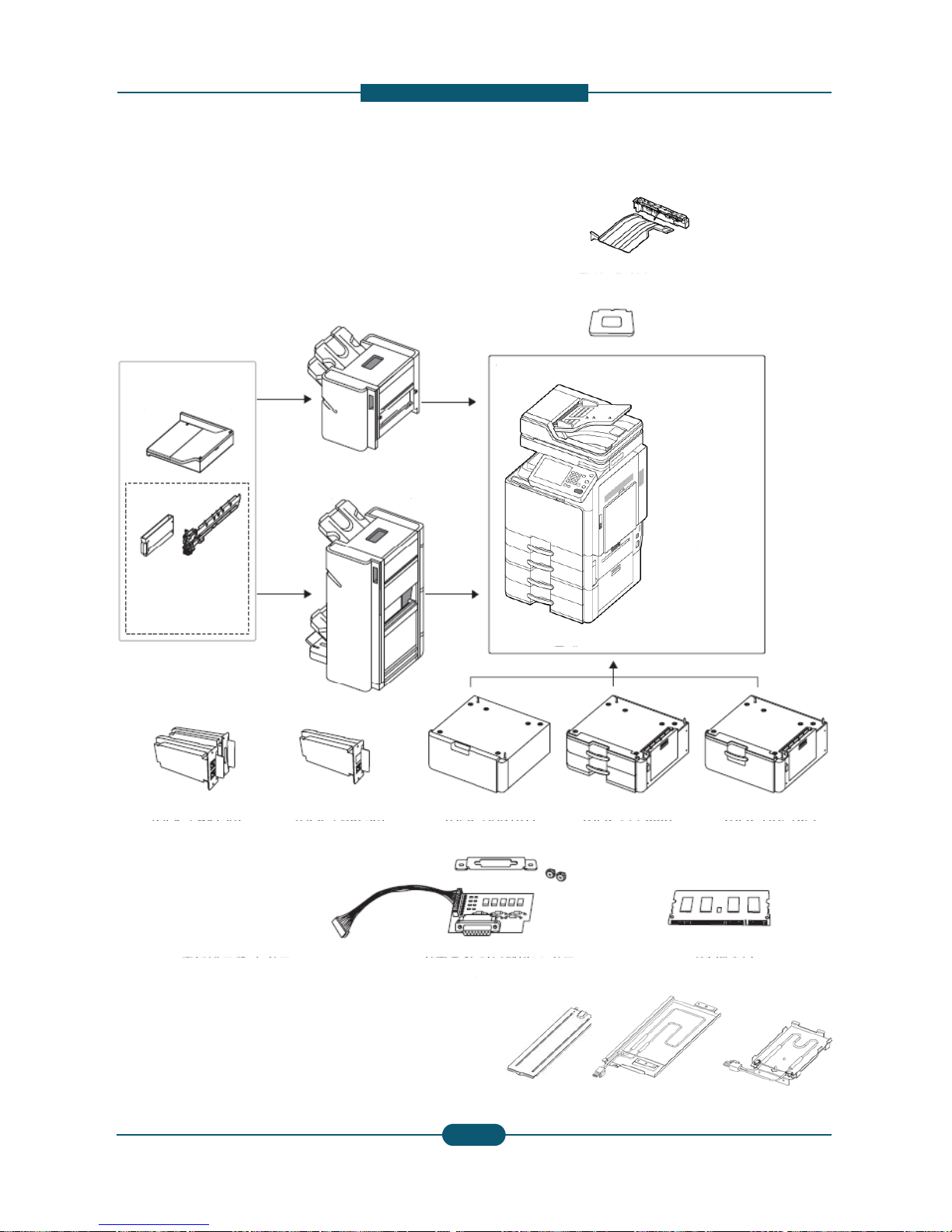
Option unit configuration
1,250-sheet standard finisher
(CLX-FIN40S)
Bridge kit
(CLX-BRG200)
3,250-sheet booklet finisher
(CLX-FIN40L)
2/3 hole Punch kit
(CLX-HPU000)
2/4 hole Punch kit
(CLX-HPU001)
S
t
Fax kit
Fax multi-line kit
(CLX
-
D
(CLX
-
FAX150)
(CLX
-
FAX250)
F
(CL
X
Service Manual
SCX-8030/8040 series
2
-
escription
Job Separator
(SCX-JST000)
Working Table
(CLX-WKT000)
Duplex Automatic Document Feeder
Main unit
and
Optional tray
High capacity feeder
(CLX
-
PFP000)
(CLX
-
HCF102)
I
kit
-KIT10F)
Expansion memory module 512M
(SCX-MEM300)
SAMSUNG ELECTRONICS
Version 0.05
6
Cassette / Scanner Heating cable
(CLX-DHK11C/12C/11S/12S)
2. Product
D
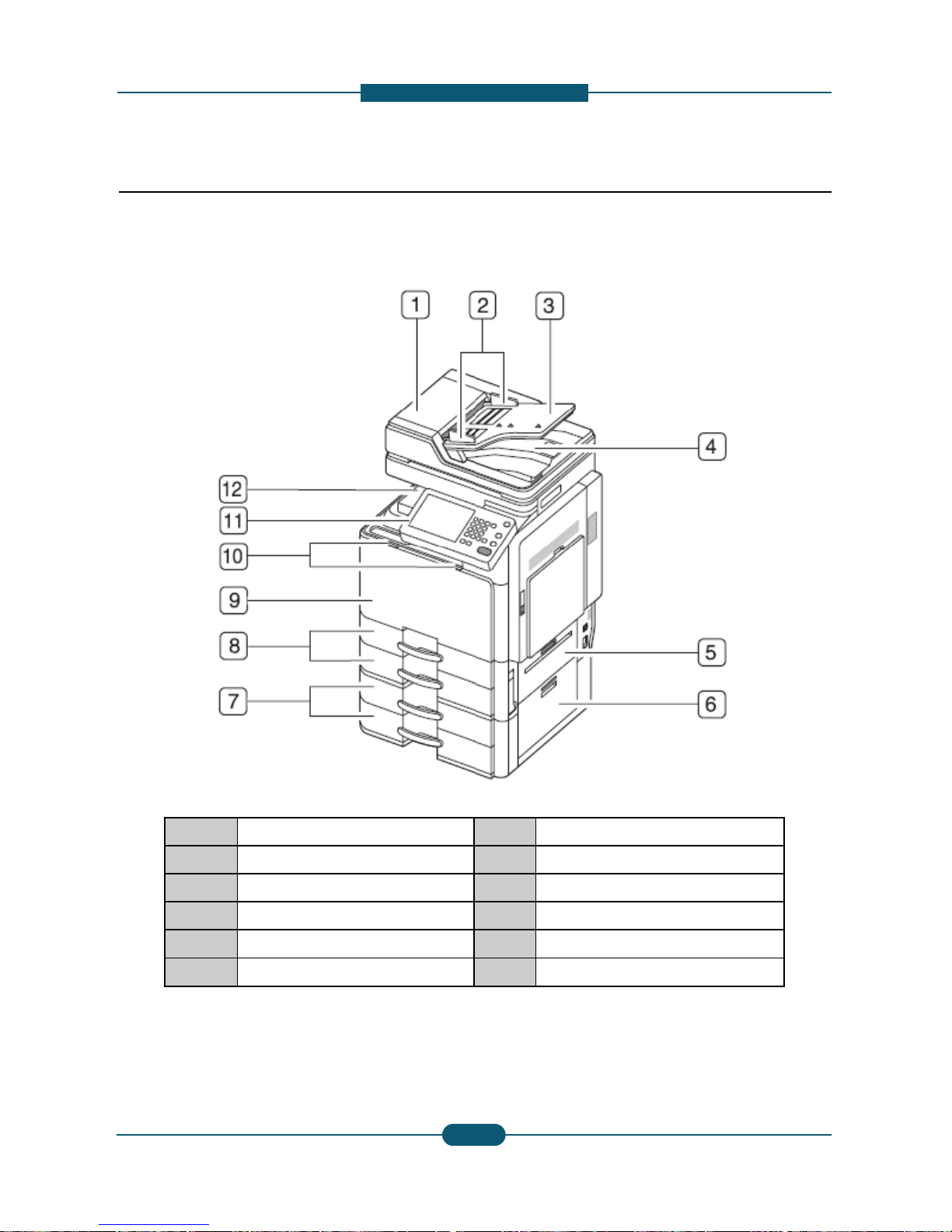
2.2 System configuration
Front view 1
1 DADF Cover
2 DADF width guides
3 DADF input tray
4 DADF output tray
5 Standard tray right bottom door
6 DCF right bottom door
* Optional device
Service Manual
SCX-8030/8040 series
2
-
escription
7 DCF (tray3, tray4)*
8 Standard tray (tray1, tray2)
9 Front door
10 Front door handle
11 Control panel
12 Center tray
SAMSUNG ELECTRONICS
Version 0.05
7
2. Product
D
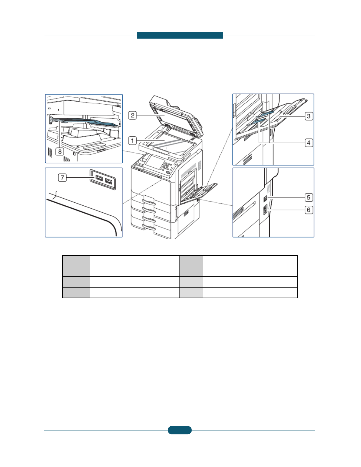
Front view 2
1
S
canner glass
2 White sheet
3 Multi-purpose tray
4 Multi-purpose tray width guide
* Optional device
Service Manual
SCX-8030/8040 series
2
-
escription
5
P
ower-switc
h
6 Power receptacle
7 USB port (2 EA)
8 Job separator*
SAMSUNG ELECTRONICS
Version 0.05
8
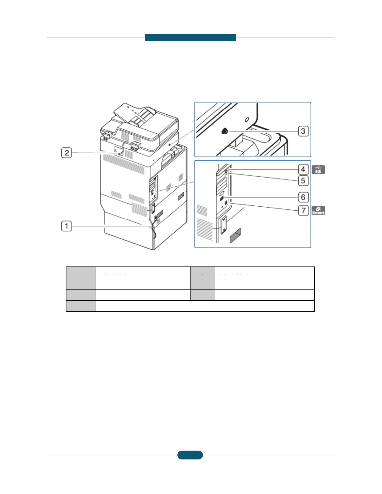
2. Product
D
Rear view
1
DCF cable
2 DADF cable
3 Scanner locking screw
4 USB port (Connection port to comp
u
Service Manual
SCX-8030/8040 series
2
-
escription
5
USB host
port
6 Finisher connector
7 Network port
ter)
SAMSUNG ELECTRONICS
Version 0.05
9
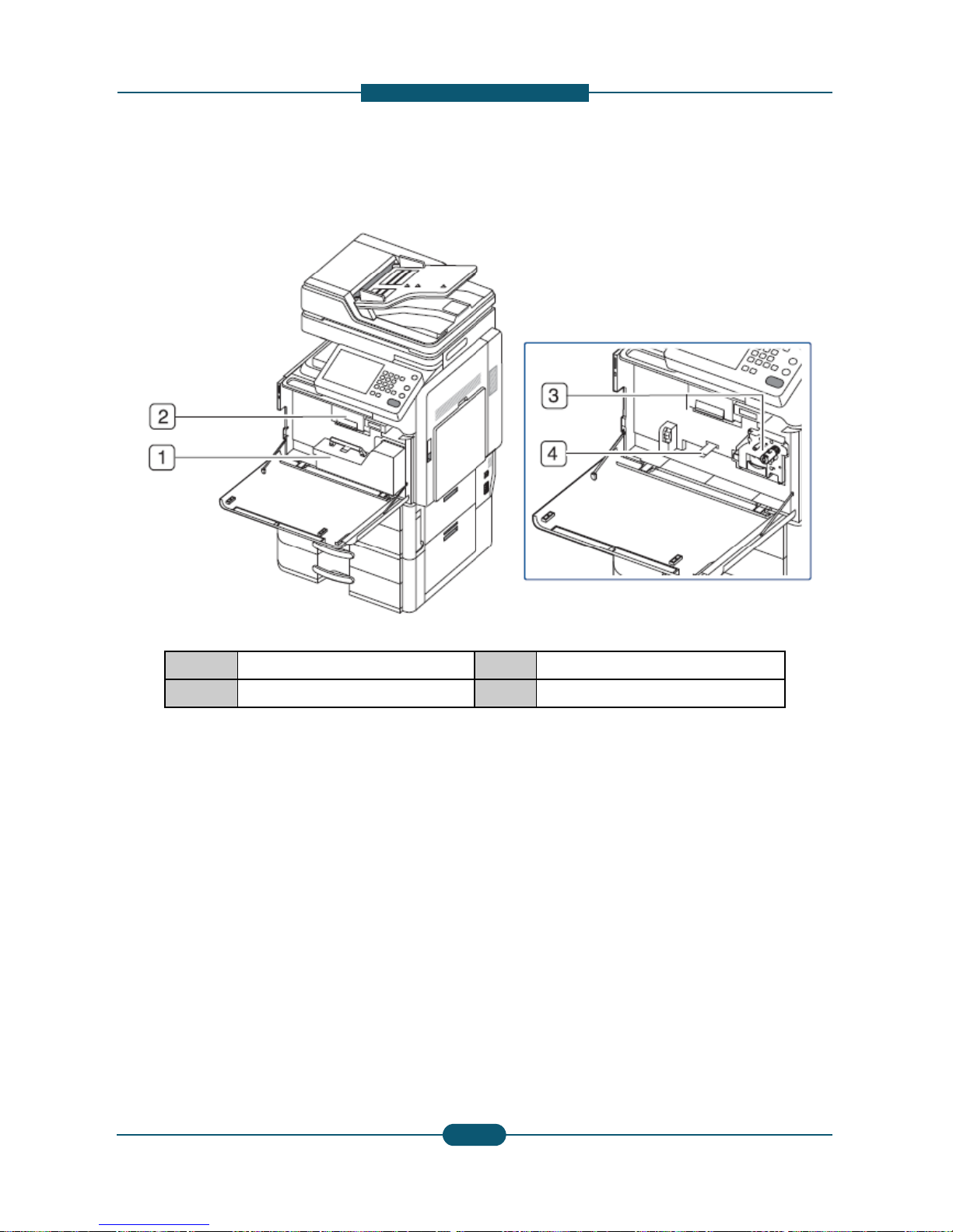
2. Product
D
Inner view
1 Waste toner container
2 Toner cartridge
NOTE
If you want to see the imaging unit, you need t
o
lever upward. Then remove the waste toner co
n
Service Manual
SCX-8030/8040 series
2-
1
escription
3 Imaging unit
4 Locking lever
remove the waste toner container. Lift the locking
tainer.
SAMSUNG ELECTRONICS
Version 0.05
0
2. Product
D
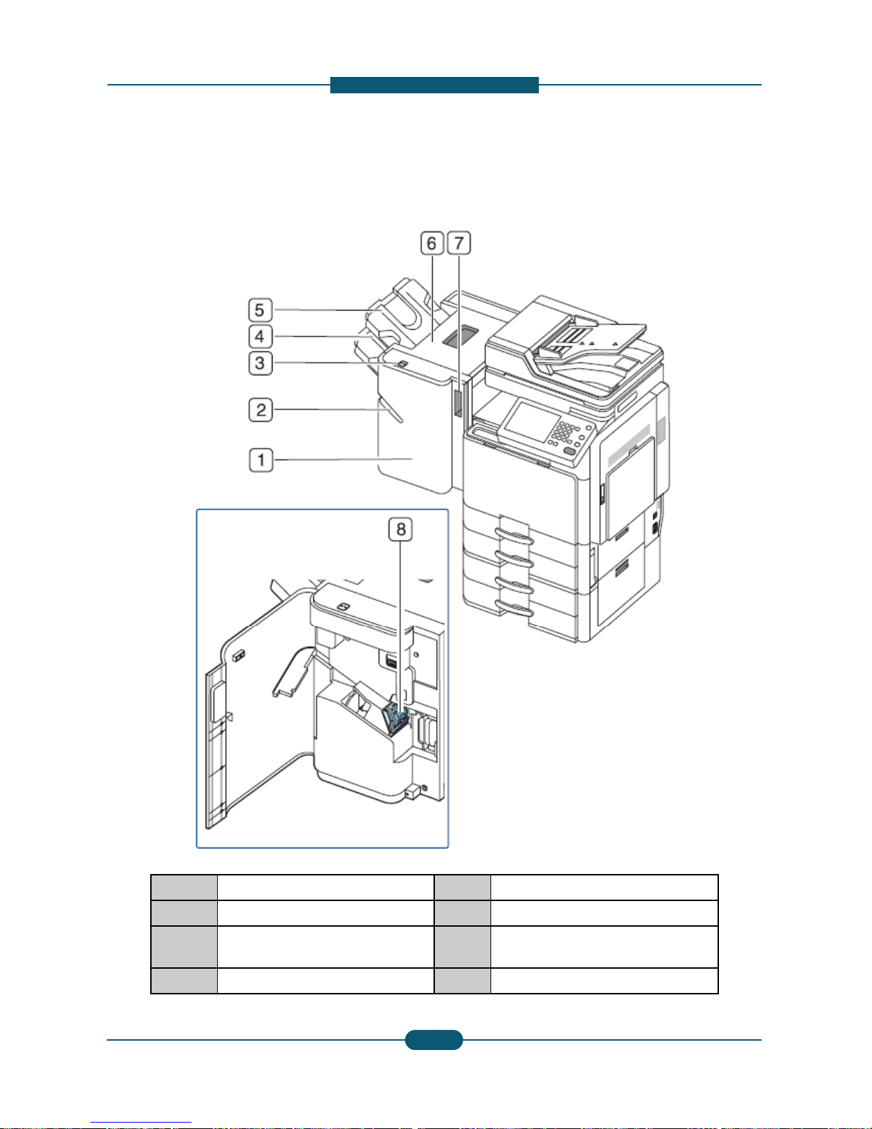
V
iew with standard finisher (option
1 Standard finisher front door
2 Manual stapler
3 Manual stapler button
4 Finishing tray
Service Manual
SCX-8030/8040 series
2-
1
escription
al)
5 Top tray
6 Top door
7 Standard finisher Front door
handle
8 Staple
SAMSUNG ELECTRONICS
Version 0.05
1
2. Product
D
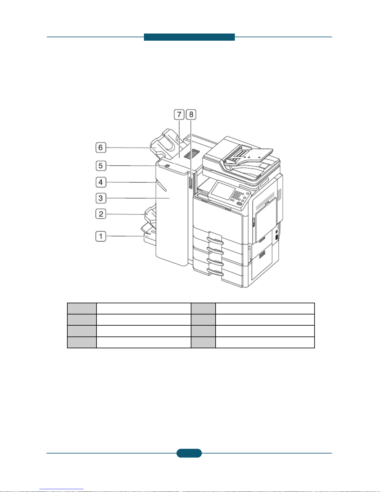
View with booklet finisher1 (option
a
1 Booklet tray
2 Finishing tray
3 Booklet finisher front door
4 Manual stapler
Service Manual
SCX-8030/8040 series
2-
1
escription
l)
5 Manual stapler button
6 Top tray
7 Top door
8 Booklet finisher front door handle
SAMSUNG ELECTRONICS
Version 0.05
2
2. Product
D
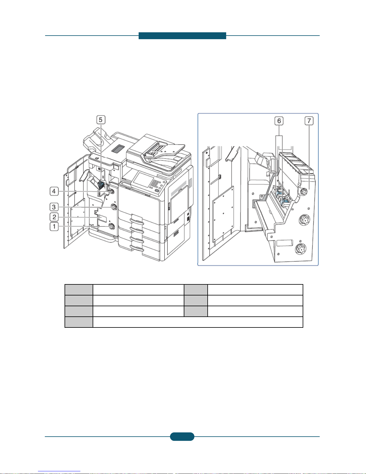
View with booklet finisher2 (option
a
1 Knife wheel
2 Booklet maker handle
3 Fold wheel
4 Booklet jam removal wheel
Note
If you want to open the booklet maker, hold the b
o
Service Manual
SCX-8030/8040 series
2-
1
escription
l)
5 Staple
6 Booklet Staple (2 EA)
7 Booklet maker cover
oklet maker handle and pull it out.
SAMSUNG ELECTRONICS
Version 0.05
3
2. Product
D
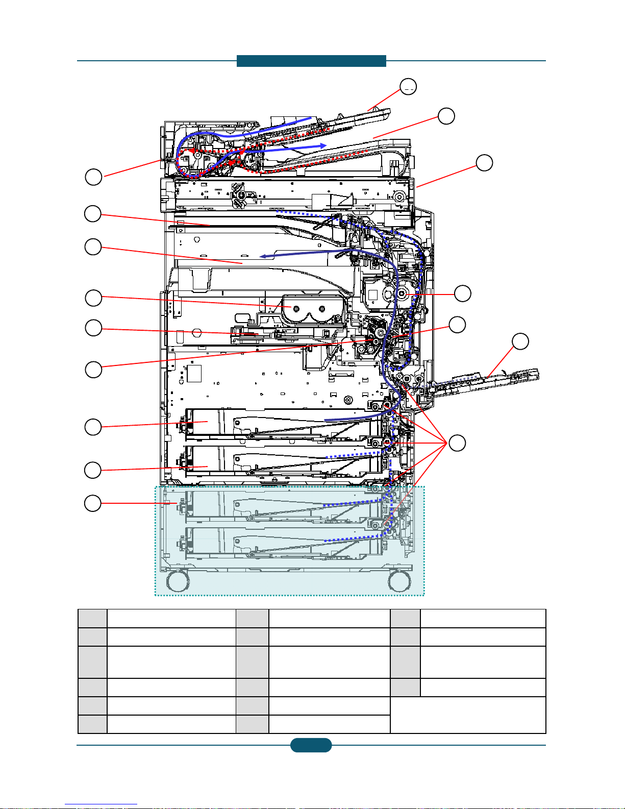
Layout
1
2
3
4
5
6
7
8
9
1 DADF 7 1sttray
2 Job separator output tray 8 2ndtray
3 Face down output tray 9 Optional
(Stand /
4 Toner cartridges 10 Pick up
r
5 Laser scanning unit 11 MP tray
Service Manual
SCX-8030/8040 series
2-
1
6 Imaging units 12 Transfer
escription
14
15
16
11
12
13
10
13 Fuser unit
14 Flatbed scanner
tray
HCF / DCF)
15 Document output tray
ollers 16 Document input tray
SAMSUNG ELECTRONICS
Version 0.05
4
roller unit
 Loading...