

Page 1
Summary of Product
Service Manual
4-1
Samsung Electronics
4
4
4. Summary of Product
This chapter describes the functions and operating principles of the main components.
4.1 Printer Components
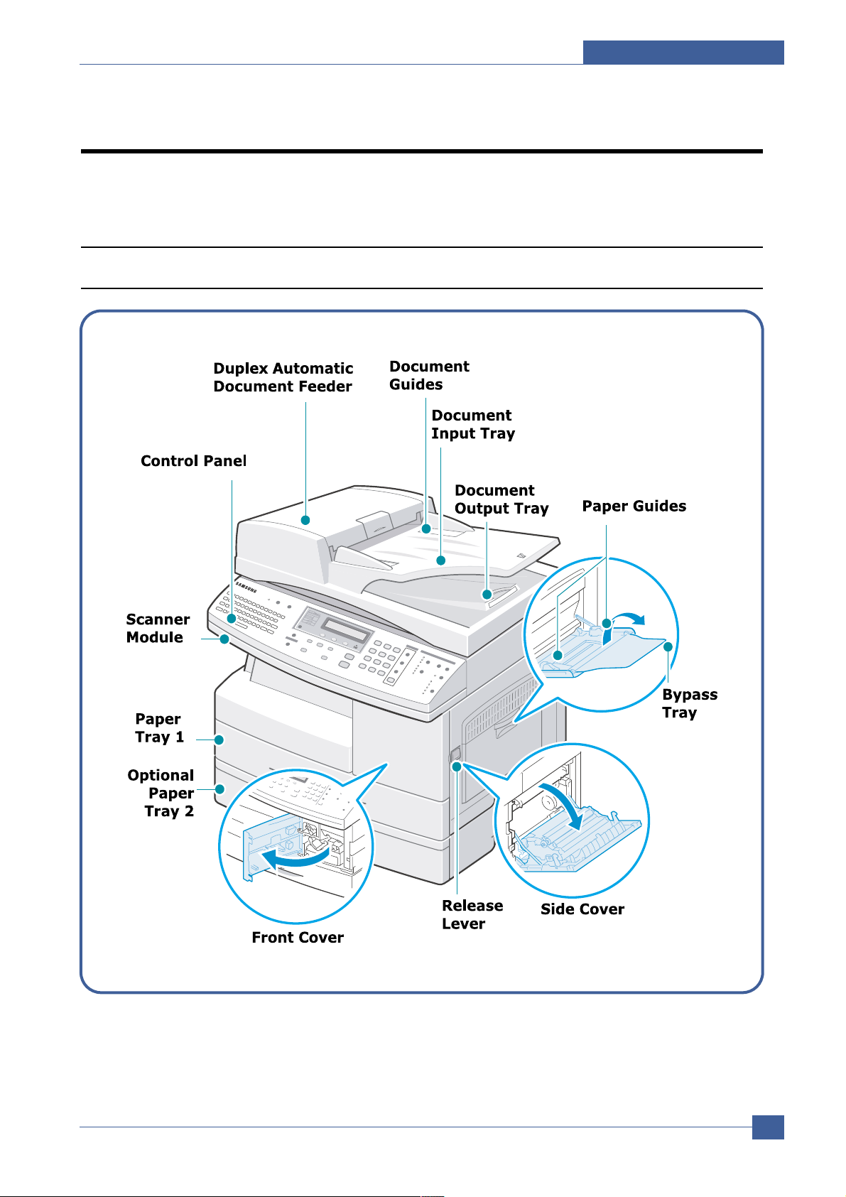
4.1.1 Front View
Page 2
Service Manual
Summary of Product
4-2
Samsung Electronics
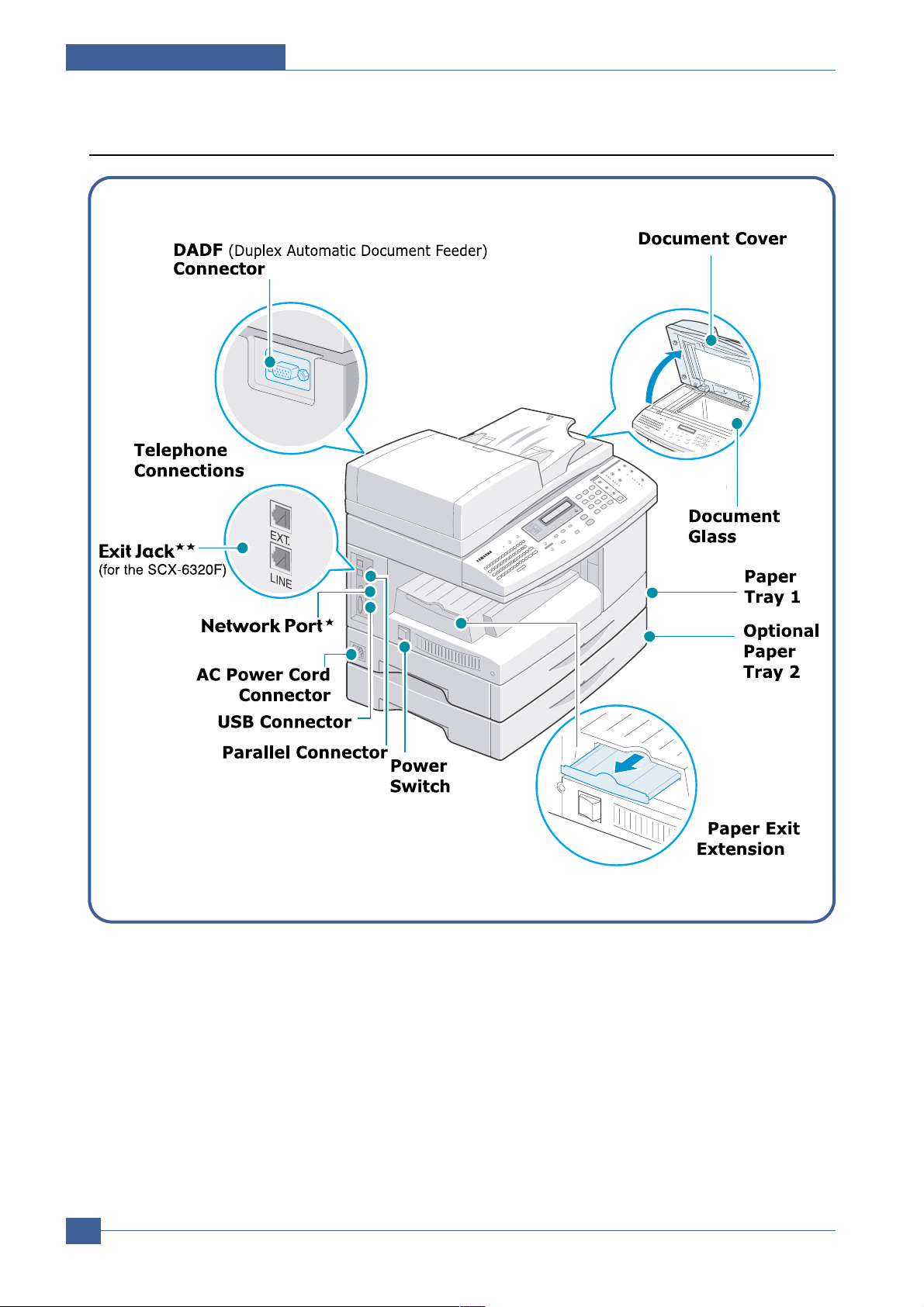
4.1.2 Rear View
* The network port is not fitted as standard on the machine.
** If your country has a different telephone connection system, this socket may be blocked.
Page 3
Summary of Product
Service Manual
4-3
Samsung Electronics
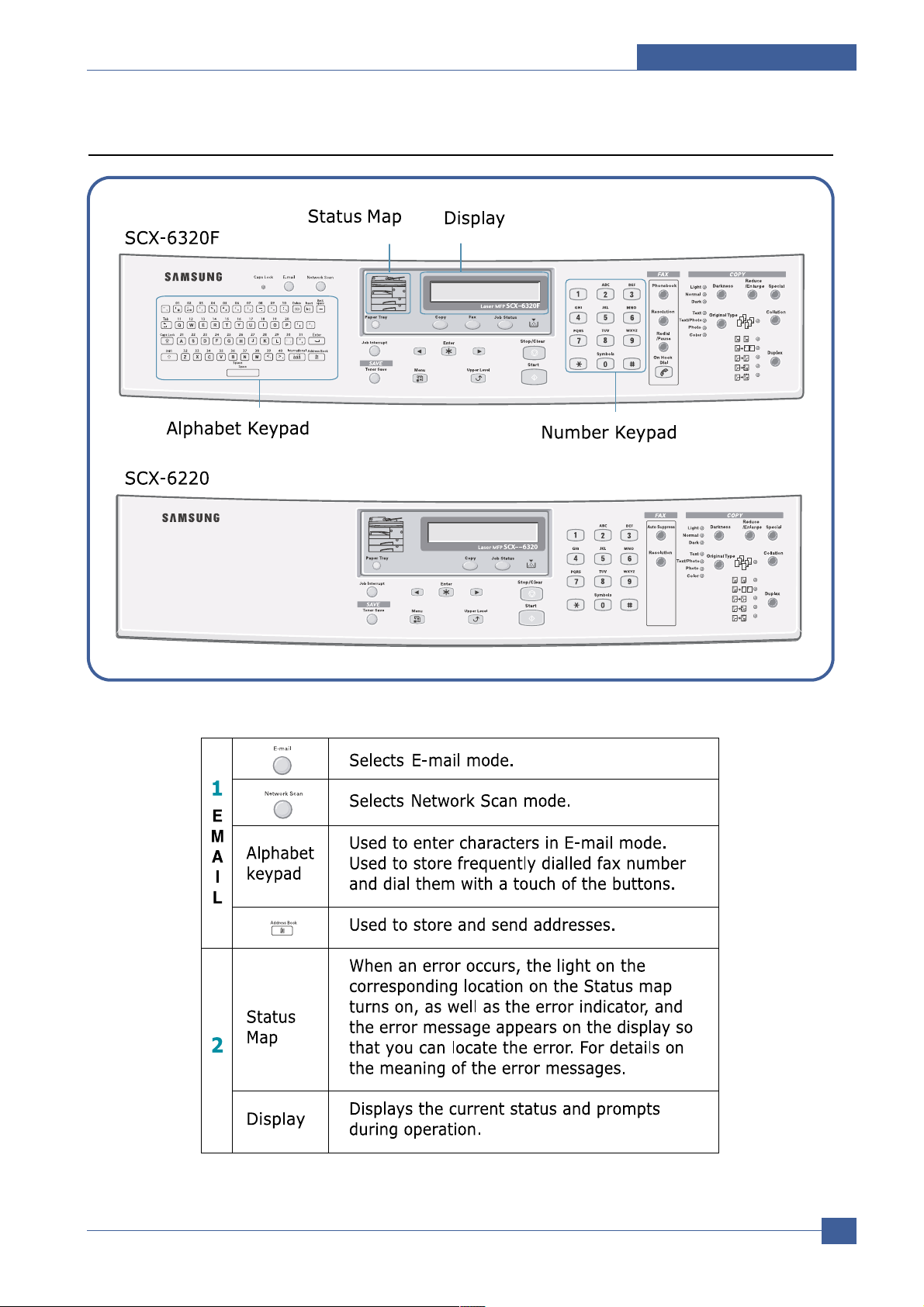
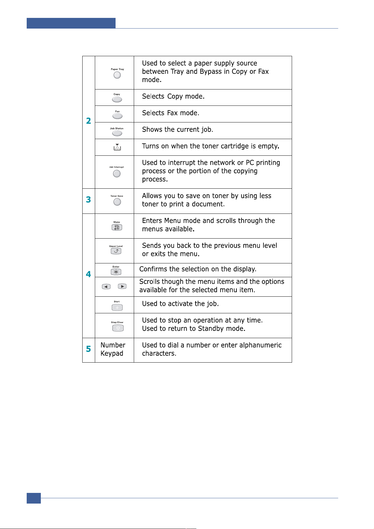
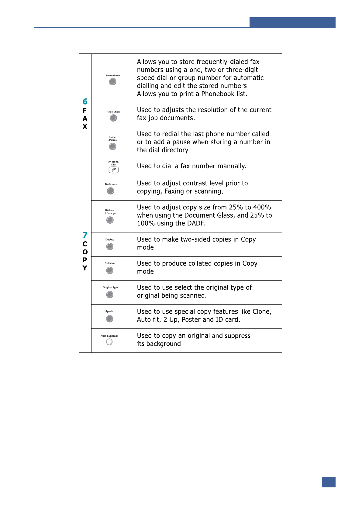
4.1.3 Control Panel (SCX-6320F & SCX-6220)
Page 4
Service Manual
Summary of Product
4-4
Samsung Electronics
Page 5
Summary of Product
Service Manual
4-5
Samsung Electronics
Page 6

Service Manual
Summary of Product
4-6
Samsung Electronics
4.2 System Layout
SCX6220/6320F can be divided into the following main constituent parts: Main Controller, Operator’s Panel,
PC Interface, Scanner, DADF, Line Interface and Power Supply. The Main Controller uses the SPGPm
processor. The Operator’s panel (OPE) and the DADF each have their own MICOM which communicates
serially with a UART built into the SPGPm processor. The Scanner uses the CIP4e processor to control the
CIS. The Line Interface is an FM336 integrated with the Main Board which communicates with the LIU at
speeds up to 33.6Kbps.
The Power Supply has both the SMPS and HVPS integrated on one PBA.
4.2.1 Feeding section
There is a universal cassette which automatically loads paper and the manual feed which supplies paper
single sheet at a time. The cassette has a friction pad which separates paper to ensure single sheet feeding, and it has a sensor, which checks when the paper tray is empty.
- Feeding Method: Universal Cassette Type
- Feeding Standard: Center Loading
- Feeding Capacity: Cassette-550 sheets (75g/m2 , 20lb paper standard)
- Multi-function tray: 100 sheet (75g/m2 , 20lb paper standard.)
- Paper detecting sensor: Photo sensor
- Paper size sensor: None
- Driven by gearing from the main motor
4.2.2 Transfer Ass’y
This consists of the PTL (pre-transfer lamp) and the Transfer Roller. The PTL shines a light onto the OPC
drum This lowers the charge on the drum’s surface and improves transfer efficiency.
The transfer roller transfers toner from the OPC drum surface to the paper.
- Life span: 100,000 sheets (in 15~30°C)
4.2.3 Drive Ass’y
- Gear driven power unit. The motor supplies power to the paper feed unit, the fuser unit, and the
toner cartridge.
- Duplex motor drives output roller for forward and reverse functions.
- DADF Unit : the DADF has its own MICOM which controls the paper feed motors.
The two motors are, like the printer drive motors, used to feed the paper through the ADF
mechanism. The ADF duplex motor is used for reversing the paper feed for double sided
originals. Both DADF motors operate a a maximum of 2940pps.
Page 7

Summary of Product
Service Manual
4-7
Samsung Electronics
4.2.5 Scanner
It reads an image with a photosensitive sensor. It consists of a CCD module, Connection board, DADF
board , AFE (Analog Front End), and Image Processor (Located in CPU), platen glass and DADF.
4.2.5.1 General Specification
• The Scanner specification is as follows:
1) Minimum Scan Line Time : 0.68ms
2) Scan Resolution : Max. 600DPI
3) Scan Width : 216mm
4) Primary Function
- Internal 12bit ADC
- White Shading Correction
- Gamma Correction
- CCD Interface
- 256 Gray Scale
4.2.5.2 CCD Imager Control Specification
• CCD Image sensor uses +5V Power and Inverter uses +24Vpower.
- CCD Max. Driving Frequency : 10MHz
- CCD Line time : 0.68ms
- White Data Output Voltage : 0.7V°æ0.5V (Mono Copy, 0.68ms/line)
- Maximum Inverter Current : 600 mA Max.(Power +24V)
4.2.4 Fusing
The temperature change on the heat roller’s surface is measured using a Thermistor. The resistance of the
Thermistor changes as the temperature changes. The value of the resistance is measured using an A to D
converter and the value is sent to the processor. The processor controls the AC power to the heat coil. If
the processor decides that the temperature is out of range an error message is displayed on the KCD
display. Refer to the table below.
Heat Coil Method
Error Description
Open heat error When preheating, it has been lower than 68°C over 15 seconds.
Lower heat error • After finishing the preheating process, the fuser has not reached 100°C (preheating stop
temperature) within 15 seconds of the temperature reaching 68°C.
• Printing
1) When the main motor is on and after 0.92 second, it has not reached 160°C
within 20 seconds.
2) After the second consecutive page, the fuser has been 20°C lower than the fusing
temperature for more than 4 seconds.
Over heat error This error is not displayed immediately when the fuser reaches 220°C.
The temperature is checked after 3 seconds. If it is over 240°C, it is error.
If the temperature has been higher than 220°C for more than 25 seconds, it is an error
even though the temperature doesn't reach 240°C.
Page 8

Service Manual
Summary of Product
4-8
Samsung Electronics
4.2.6 DADF (Duplex Auto Document Feeder)
4.2.6.1 DADF Specification
• Duplex drive mechanism controlled by its own One Chip MICOM.
• It sends/receives command from the Main Board using UART.
- The 2 Motors, DADF MOTOR & DUPLEX MOTOR, are driven at a maximum of 2940pps.
- MOTOR DRIVER : A3977(Allegro) x 2EA
- Driving Power : 24V DC
- Driving Mode :
COPY : 1470pps
SCAN : 400pps ( 600dpi) ~ 2940pps (75dpi)
FAX : Super Fine : 1470pps (1-2phase)
Fine : 1470pps (2-2phase)
Normal : 1470pps (2-2phase)
Minimum Scan Line Time : 0.72msec -> 0.68ms
CCD Driving : 0.72msec -> 0.68ms
4.2.6.2 DADF Sensor
* DADF Capacity : 50sheets
4.2.6.3 DADF Rubber
Type Photo interrupt
Location ADF B'D
Heating area Max. current 50mA
Max. voltage 5V
Output Logic "H" Document present
Logic "L" Document not present
Location : Doc. Sensor To detect document in document feed tray
Doc. Width Sensor To detect document width
Doc. Length Sensor To detect document length
Regi Sensor For Document Registration
Scan Sensor Detects the leading and trailing document edge at the CCD
Gate Sensor To identify Duplex start point
Duplex Sensor For registration of document in Duplex path
Door Open Sensor To remove document jam in feed area
Exit Open Sensor To remove document jam in exit area
Material SI rubber
Life 20,000 sheets (A4 standard)
4.2.6.4 DADF Roller
Diameter 25.06mm
Material EPDM
Life 50,000 sheets (A4 standard)
Page 9

Summary of Product
Service Manual
4-9
Samsung Electronics
Optical Resolution Real 600 dpi
Beam Diameter Main Scan Beam Diameter 75 +20/-10 um
Sub Scan Beam Diameter 80 +40/-10 um
Beam diameter deviation (Main/Sub-scan) 30 um/ 50 um
Laser Wavelength 785 +20/-15 nm
power 0.365 mW ± 0.02 mW
f Characteristic Focal distance 136.6 mm
Effective angle (2 ) 90.56°(Based on 216mm Image Width)
Scan Width Valid Scan Width 210 mm
Max Scan Width 216 mm
Scan Line Characteristic Scan line curvature under 1.0 mm
Scan line inclination under 1.0 mm
Sync Detecting position 121.7 mm
Sync PULSE Width 1 u sec or more
4.2.7 LSU (Laser Scanner Unit)
This is the core of the laser printer. It converts the video data received from the computer into an electrostatic latent image on the surface of the OPC drum. This is achieved by controlling the laser beam and exposing the surface of the OPC drum to the laser light. Arotating polygon mirror reflects the laser light onto the
OPC and each side of the mirror is one scan line. The OPC drum turns as the paper feeds to scan the
image down the page.
The /HSYNC signal is created when the laser beam from LSU reaches the end of the polygon mirror and
this signal is sent to the controller. The controller detects the /HSYNC signal to adjust the vertical line of the
image on paper. In other words after the /HSYNC signal is detected the image data is sent to the LSU to
adjust the left margin on the paper.
Page 10

Service Manual
Summary of Product
4-10
Samsung Electronics
4.2.8 CRU (Customer Replaceable Unit) Section
The Toner cartridge and Drum cartridge are consumable items which require replacement. When each cartridge
nears the end of its service life a message will be displayed in the control panel to inform the user that the
cartridge requires replacement.
Store CRU cartridges in a location that is not subject to rapid changes in temperature or humidity.
4.2.8.1 Toner Cartridge Specification
The Toner CRU has a CRUM to enable the firmware to differentiate Samsung and third party versions as well as
detect CRU presence.
• Toner Level Sensor : YES
• Low Toner : Message displayed on LCD "Toner Low"
There are 2 conditions which will cause the "Toner Low" message to appear on the control panel.
a) This state is detected by an optical sensor which detects the physical amount of toner remaining
b) or a decision is made by the F/W when 12,000 pages have been printed after the toner cartridge has
been replaced. This F/W decision is needed to prevent the waste toner bin from overflowing.
The machine can continue making copies when this message is displayed. However, preparation of the new toner
cartridge is recommended.
• Toner Empty : Message Displayed on LCD "Toner Empty"
There are 2 conditions which will cause the "Toner Empty" message to appear on the control panel.
a) When the toner detector indicates that toner has run out
b) After an additional 300 pages have been printed after entering the "Toner Low" state.
"Toner Empty" is written to the CRUM and a message appears on the UI. To avoid faint or otherwise poor quality
printing replace the toner cartridge.
When “Toner Empty” message is displayed on LCD, the print function of machine stops to avoid faint or poor printing
quality .
If the continuous print is needed without replacing the new toner cartridge, follow the next steps.
Push [menu] button repeatedly, then Select [Machine Setup].
Push [ ] or [ ] button repeatedly, then Select [Ignore Toner Empty].
* “ON” : Continue to print.
* “OFF” : Stop printing (Default).
If the maximum printing counts arrive at 12,300 pages (300 prints after 12,000 prints), “Toner Empty” / “Replace
Toner” message is displayed on LCD together and the print function of machine stops to prevent the waste toner
bin from overflowing. Besides, [Ignore Toner Empty] function is fixed only [OFF].
• CRUM : Yes (EEPROM in Toner Cartridge)
• White glove installation : Yes (meets required standards)
• Life (Service) Time :
The service life of a cartridge is based on an estimated printing with 5% coverage on one A4 or Letter page at
the default density settings in the machine.
- (Starter) 8,000 images A4 or Letter page, ISO 5% coverage (ISO 19752 Stnadard Pattern)
- (After-Market) 8,000 images A4 or Letter page, ISO 5% coverage (ISO 19752 Stnadard Pattern)
* Toner Cartridge Yield : Average cartridge 8,000 standard pages.
Declared yield value in accordance with ISO/IEC 19752.
Page 11

Summary of Product
Service Manual
4-11
Samsung Electronics
4.2.8.1.1 CRUM for Toner cartridge
Branded Samsung toner cartridges must be used in the SCX6220/6320F.
The Usage data saved in the CRUM are either used by other features or are printed on the billing / counters list.
Toner level gauge - Toner Level has Normal, Low, and Empty states detected using a Toner sensor.
Note : The SCX-6320F does not support simulated toner gauge feature.
Usage data saved in CRUM
- Vendor (Vendor name)
- Capacity (Toner Cartridge Capacity)
- Product Date (Toner Cartridge production date)
- Install Date (Toner Cartridge installation date)
- Serial (Serial number)
- Total pages (Page count using this Cartridge)
- Toner Status (Toner Level : Normal, Low, Empty)
Non-Samsung cartridge - Faulty CRUM: Stop printing
(UI: Invalid Cartridge) - Non Samsung Cartridge: Stop printing
- Cartridge with inappropriate vendor ID: Stop printing
- Cartridge with different vendor ID from vendor ID of machine: Stop printing
“Invalid Cartridge” will be displayed on LCD in above 4 cases, and Copy/Fax/PC
job printing will be stopped (except printing Reports at “TECH MODE”)
CRUM Feature Sub features
Page 12

Service Manual
Summary of Product
4-12
Samsung Electronics
4.2.8.2 Drum Cartridge Specification
The OPC Drum Cartridge has a fuse to enable a new drum to be detected and to reset the Drum Page counter.
• Low Drum Warning : Message displayed on LCD "Drum Warning" after printing 18,000 images.
• Out-of -Drum : Message displayed on LCD "Replace Drum" after printing 20,000 images, or after an additional
2000 images following "Drum Warning"
In order to maintain the consistency of print quality, the drum cartridge should be discarded after reaching the end
of its life. When a new drum is inserted into the set the presence of a fuse is detected and the drum page counter
is reset and the electrical fuse is blown
An OPC drum cartridge is extremely sensitive to light. Exposure to strong light can deteriorate the drum cartridge,
resulting in poor performance and poor print quality.
• Life (Service) Time : 20,000 images.
The estimate of the service life of a drum cartridge is based on an average print job performed with A4 or Letter
size paper loaded. If the user frequently prints with lower than 100% duty or uses the duplex function heavily, the
service life of the drum cartridge will be shorter than above. (See the page 4-13)
4.2.8.3 Billing / Counters List
This list provides the usage data (page count) for the Drum cartridge, Toner cartridge, the machine and
DADF/Platen scan page count. The “Billing/Counters List” is printed as follows.
<in User mode>
Push [menu] button repeatedly, then Select [Reports].
Push [ ] or [ ] button repeatedly, then Select [Billing/Counters].
Push the [Enter] key
<in Tech mode>
Push [menu] button, then Select the number [6] key.
Push [ ] or [ ] button repeatedly, then Select [Billing/Counters].
Push the [Enter] key
Page 13

Summary of Product
Service Manual
4-13
Samsung Electronics
Billing / Counters List
------------------------------------------------------------------------------------------------------------------------------------------------------------Total impressions : xxx ( printing page count of the machine )
Toner impression Count : xxx ( printing page count of the toner cartridge )
Drum impression Count : xxx ( printing page count of the drum cartridge )
DADF Scan Page Count : xxx ( DADF scan page count of the machine )
Platen Scan Page Count : xxx ( Platen scan page count of the machine )
Replaced Toner Count : xxx ( Replaced Toner cartridge count of this machine )
Replaced Drum Count : xx ( Replaced Drum cartridge count of this machine )
*Equivalent Drum Revolution Rate : xxx% (xxx)
*(Projected Page Counts)
CRUM Information
*Vendor : SAMSUNG(xxx) [xxx] (Vendor Name)
Capacity : 8K (Toner Cartridge capacity)
Product Date : xxxx.xx (Toner Cartridge production date)
Install Date : xxxx.xx.xx (Date the toner cartridge was installed)
Serial : CRUM-xxxxxxxxxxx (Serial number of the toner cartridge)
Total Pages : xxxx (Printing page count of this toner cartridge)
Toner Status : x (0:Normal, 1:Toner Low, 2:Toner Empty)
*Equivalent Drum Revolution Rate: The ratio of current drum revolution to that under the average user’s printing
behavior 100% (Customer usage assumption). If the ratio is over 100%, the machine is used mainly for low duty
cycle (individual or duplex printing job). Otherwise, if the ratio is under 100%, the machine is used mainly for high
duty cycle (continuous or simplex printing job).
This data is printed only in Tech mode.
This rate can be expressed as follows.
[Equivalent Drum Revolution Rate]=[Projected Page Counts] / [Drum impression count] %
*Projected Page Counts : This means the converted value of current drum revolution into the page count under
the average user’s printing behavior (customer usage assumption).
This data is printed only in Tech mode.
* Vendor : SAMSUNG( xxxxxx ) [ xxx ]
Vendor name of the machine : example [EXP]
Vendor name of the toner cartridge (CRUM) : Example (EXPORT)
If the vendor name of the toner cartridge (CRUM) corresponds to the vendor name of the machine, the machine
works normally.
Otherwise, if the vendor name of the toner cartridge (CRUM) does not correspond to the vendor name of the
machine, “Invalid Cartridge” message will be displayed on LCD
Page 14

Service Manual
Summary of Product
4-14
Samsung Electronics
4.3 System Description
4.3.1 System controller architecture
SCX6220/6320F can be divided into the following main constituent parts: Main Controller, Operator’s Panel, PC
Interface, Scanner, DADF, Line Interface and Power Supply. The Main Controller uses the SPGPm processor
which is common to many FAX and Printer products.
PC direct interfaces, USB2.0 and IEEE1284, are implemented on the main PBA. Network support is implemented
on a separate Network Interface card.
Each Part is designed with emphasis on Common-Use/Standardization with other models as independent
modules.
4.3.1.1 System Block Diagram
Scan Module
Image
Sensor
AFE
IP
SRAM
(User Settings)
SOC
SDRAM
Motor
Driver
MODEM
LIU
Main Board
Flash
(basic oper
ating code)
SDRAM/
Flash Rom
(PS3)/Fonts
Option Memory
GIO
sensorsFANMotors
LSU
Direct I/F
(on Main PBA)
IEEE1284
PC
NW
IEEE1284
Flash
USB2.0
Flash
(PCL6)
Network I/F Kit
Network I/F
Page 15

Summary of Product
Service Manual
4-15
Samsung Electronics
4.3.2 Main Controller
The Main Control Part comprises a main processor (SPGPm) and a graphics processor (CIP4E) which, by
adopting the dedicated processors for Fax & LBP machines, is implemented on a single PBA.
The Scanner Part comprises DADF & CCD and is connected with Main PBA through a cable harness.
4.3.2.1 SPGPm Printer controller
• ARM946ES processor
- 32-bit RISC embedded processor core
- 16KB instruction cache and 16KB data cache
- No Tightly Coupled Memory
- Memory Protection Unit &CP15 control program
• Dual bus architecture for bus traffic distribution
- AMBAHigh performance Bus (AHB)
- System Bus with SDRAM
• IEEE1284 compliant parallel port interface
• Printer Video Controller for LBP engines
• Graphic Execution Unit for Banding support of Printer Languages
• Printer Video Controller for LBP engines
- PVC : Printer Video Controller without RETAlgorithm
- HPVC : Printer Video Controller with RET algorithm
(Line Memory & Lookup Table Memory : 512 x 8 , 4096 x 16)
• Engine Controller
- Motor Control Unit
- Motor Speed Lookup Table Memory (128 x 16 x 2)
- Pulse Width Modulation Unit
- 4 Channels are supported
- ADC Interface Unit
- 3 ADC Channels are available
- ADC Core (ADC8MUX8) maximum clock frequency :3 MHz
• USB 2.0 Interface
• Package : 272 pins PBGA
• Power : 1.8V(Core), 3.3V(IO) power operation
• Speed : 166MHz core(ARM946ES)operation,60MHz bus operation
4.3.2.2 Flash Memory
It stores the system program, this can be updated by downloading the system program through the PC Interface.
It is also used to store the FAX Journal, One Touch Dial and Speed Dial lists.
• Capacity :4M Byte
• Access Time :70 nsec
Page 16

Service Manual
Summary of Product
4-16
Samsung Electronics
4.3.2.3 System Memory (SDRAM)
• Capacity: SCX6220 32MByte expandable up to 160MByte, SCX6320F 48MByte expandable to 176MByte.
• Optional Additional DIMM : 16MB / 32MB / 64MB /128MB. Additional memory above 48Mbytes fitted in the
DIMM socket is used for printing
• Type : SDRAM 133MHz , 16bit
- Abattery backup power supply is used to ensure faxes stored in memory are not lost when power is off.
4.3.2.4 System Data Memory (SRAM)
This memory is used to store client settings and operation variables. It has a battery supply to maintain values
when power is off.
Note – Option Kit includes an additional
32MB memory
SCX6220 SCX6220 +
Net. Option
SCX6320F SCX6320F
+ Net. Option
System Working Memory Area / Scan Buffer 8MB 8MB 8MB 8MB
Printing System Working Memory Area 24MB 24MB 24MB 24MB
FAX memory (in DIMM socket) 16MB 16MB
Scan to Email (in DIMM socket) 32MB 32MB
Page 17

Summary of Product
Service Manual
4-17
Samsung Electronics
4.3.3 Network Interface Card (NIC) Block Diagram - Option
The NPC card is supplied as an option kit (not factory fitted). It is supplied with a Qwerty keyboard and a 48MB
memory module. This kit is required in order to support EMAIL features.
Note The 16MByte memory fitted in the DIMM socket (SCX6320F only) must be removed and discarded.
1) CPU (NetOne)
This device includes IEEE802.3 MAC Core, UART, USB host, and IEEE1284 Host controller and is based on a
32Bit RISC processor having an ARM7 Core. It converts/uses 25MHz input clock into 48MHz System clock by
using internal PLL logic for use with the internal USB I/F. It has an embedded 8KB SRAM. The NPC card
exchanges data with the Main Controller PBA through the SDRAM using a 16 Bit Data Bus.
Communication between the Main PBA and CPU uses a high-speed/high-efficiency DMAtransfer process
through Shared Memory embedded in NetOne.
Note The SCX-6320F does not use the USB Interface which is embedded in NetOne.
2) ROM (Flash Memory)
The NPC used in the SCX-6320F has 2MB of Flash Memory for the operating System Program.
This Flash Memory stores the NPC Firmware which controls the entire Network Protocol and software for
Embedded Web Service & Network Management.
This Flash Memory can be upgraded through Network by using the EWS (Embedded Web Server) or SyncThru
Management software.
Regulator
80
p
i
n
C
o
n
n
e
c
t
o
r
Clock
DRAM
USB2.0 Controller
USB Jack
Flash ROM EEPROM IEEE802.B 11
PCL6
Font ROM
(Flash ROM)
Downloadable Fonts
Memory
(Flash ROM)
CPU
Net One
PHY
RJ-45
LED
LED
Ethernet Interface(10/100T) Block
USB Block
Fonts Memory Block
Page 18

Service Manual
Summary of Product
4-18
Samsung Electronics
3) RAM
16MB SDRAM is used as System Program buffer or Network Data buffer.
4) PHY
The Physical Network interface driver, it requires a 25MHz clock input.
5) RJ-45
6) LEDs
Comprising 2 LEDs that display the Network Link status and System Operation status.
7) Regulator
It converts 3.3V which is supplied from Main Controller PBA into 1.8V for CPU core operation.
8) Clock
The System clock which is needed for the Network Card operation, it needs a precision 25MHz ±50ppm X-tal
source.
9) EEPROM
Non-volatile memory for storing Network setting parameters, it stores various parameters e.g. TCP/IP and Netware
settings.
10) IEEE802b.11
Whilst the NPC card is capable of supporting the Wireless interface module this is not implemented in
SCX6220/6320F.
11) 80 pin Connector
This connector passes all of the electrical signal required for communication between the Main PBA and the
NPC. This comprises Address Bus, Data Bus, Control Bus and Power signals.
Page 19

Summary of Product
Service Manual
4-19
Samsung Electronics
4.3.4 Option Memory (DIMM)
The SCX-6320F provides 3 memory Extension Slots on the Main PBA.
Of the 3 Slots, one is for FONT ROM Extension, one is for PostScript support and the other is for SDRAM
Extension.
The FONT ROM Extension Slot is for supporting graphical languages.
The PostScript Extension slot is used when the Optional Postscript 3 ROM is fitted.
The SDRAM Extension Slot is used when the Network Kit is fitted and supports memory for the Scan-To-Email or
FAX message receive functions
The ROM Module for PS3 should be installed in PS Slot, and SDRAM Module for Scan-To-Email or Fax should be
installed in the RAM Slot. Incorrect installation will cause the SCX6220/6320F malfunction.
4.3.4.1 Memory for Scan-To-Email / FAX (SDRAM)
It is connected to the SDRAM BUS of the CPU (SPGPm) on the Main PBA and provides the memory space to
support Scan-To-Email and Fax message storage.
SCX-6220:
• Expansion SDRAM fitted in the DIMM socket is only for Scan-To-Email
- This extra memory is to support Scan-To-Email or Network Scanning when the optional NPC, Qwerty
Keyboard and Memory kit is fitted into the base model without FAX support.
- SIZE : 32 MB (Standard), If necessary it can be extended using 64MB or 128MB SDRAM DIMMs.
This extra memory beyond 32Mbytes is used for printing
SCX-6320F:
• Expansion SDRAM fitted in the DIMM socket is used for Scan-To-Email and FAX storage
- This extra memory is to support Scan-To-Email or Network Scanning when the optional NPC, Qwerty
Keyboard and Memory kit is fitted into the FAX model (SCX6320F).
- 16Mbytes of Buffer Memory for storing faxes when Secure Receive is enabled or when the paper has
run out is fitted in the DIMM socket. This is removed and replaced by a 48MByte memory when the network kit is installed.
Of this 48Mbytes 16Mbytes is still used for the FAX features. The remaining 32 MB is used for the Scan
to Email feature.
If necessary memory size can be extended using 64MB or 128MB SDRAM DIMMs This additional
memory will be used for printing.
The fax memory needs Battery Backup, and the Backup time will change according to memory size.
The standard Fax memory of The SCX-6320F is 16MB and the battery provides more than 72 Hrs. of
memory backup power.
4.3.4.2 Flash Memory for PostScripr3
The PS ROM is connected to the ROM BUS of the CPU (SPGPm) on the Main PBA and provides PostScript3
support.
This FLASH Memory can be upgraded using the RCP (Remote Control Panel) or EWS (Embedded Web Server).
Postscript support is an optional feature purchased separately.
Page 20

Service Manual
Summary of Product
4-20
Samsung Electronics
4.4 FAX FEATURES
4.4.1 ITU-G3 Compatibility
The SCX-6320F is compatible with G3 communication mode, and is not compatible with G1 and G2.
ITU-T: The International Telecommunications Union, a committee created to set international standards for
telecommunications.
4.4.2 Scan Width and Resolution
The SCX-6320F utilizes a scan width of 216mm Max., 208mm effective and provides optical 600dpi-scan
resolution. In the Fax mode, 203x98dpi (Normal), 203x196dpi (Fine), 300x300dpi (Superfine), 203x392dpi, and
406 x 392 dpi (super fine) resolutions are supported. When storing the scanned image data into memory for
transmission, if the Superfine resolution mode is selected this will be changed to Fine resolution automatically as
the set cannot determine, before contact is established, if the remote machine has the capability to support
Superfine resolution, i.e. the Superfine resolution is supported only for direct transmission.
In the Scanner mode, 75dpi through 600dpi resolutions are supported optically and higher resolutions up to
4800dpi can be supported by interpolating via the bundled Twain driver.
4.4.3 Scan Speed
Scan speed indicates the speed at which a machine scans a page and is normally expressed in 1.4sec per page
with Standard resolution from a document in the DADF. The SCX-6320F is capable of scanning a page for
transmission in just 3 seconds (based on ITU-T No.1 Chart, MMR compress).
4.4.4 Automatic Reduction when Receiving Data
When receiving a document that is as long as or longer than the paper installed in the product, the SCX-6320F
can reduce the data in the document to fit the recording paper size set by the end-user. The machine can reduce
the incoming data in vertical and horizontal direction. Otherwise, the incoming page may need to be divided into
two pages with only a few centimeters on the second page. The few centimeters on the second page can be discarded by setting end-user options. (Discard size options) If the supplied paper is not matched with the paper size
set by the end-user, the reduced and printed image data may not be printed correctly. In order to support
Automatic reduction operation, the memory has to have a capability to receive a one-page image data completely.
Sometimes if the image data is bigger than the memory capacity, for example, full image with Superfine Photo resolution, the image cannot be received.
Page 21

Summary of Product
Service Manual
4-21
Samsung Electronics
4.4.5 Modem Speed
The SCX-6320F can transmit code at a maximum speed of 33600 bits per second. The SCX-6320F will
compensate for fluctuating phone line quality by stepping-down in modem speeds (33600 to 28800 to 26400-to
21600 to 19200 to 14400 to 12000 to 9600 to 7200 to 4800 to 2400) to improve the probability that a fax
transmission will be completed on the first attempt. Normally, 33.6KBPS can transmit one page in 3 seconds
and 14.4KBPS at 7 seconds, but at 9.6KBPS the modem takes 10~12 seconds.
(ITU-T No.1 chart at standard resolution using memory transmission)
4.4.6 Error Correction Mode
ECM is a communications mode which compensates for poor line quality and ensures accurate, error-free
transmissions to any other ECM-equipped fax. However the transmission speed is slower than when using
standard mode.
4.4.7 Compression/Decompression
The SCX-6320F can compress the scanned image data to transmit fax data or decompress to print out received
fax data using MH/MR/MMR/JBIG/JPEG (transmission) (ITU-T T4/T6) compression/decompression algorithms.
4.4.8 256 Level Half-toning
This feature is used when transmitting photographs or documents with halftones. The enhanced image feature
gives documents the appearance of more grayscale levels using the Error-Diffusion method.
4.4.9 Telephone Answering Device (TAD) Interface
ATAD device is attached to the EXT line jack. The SCX-6320F supports ANS/FAX mode to receive fax message
during TAD device operation.
4.4.10 Memory Capacity
Memory capacity for Fax reception is 16 Mbytes which is used to receive fax data successfully when there is no
paper there is a paper jam or when using memory transmission / broadcasting / delay or secure receive functions.
The memory can be backed up for about minimum 72 hours when Power is off. (This can vary if additional memory
is fitted in the expansion socket.) Sometimes if the image data is bigger than the memory capacity, for example,
full image with Superfine Photo resolution, the image cannot be received. Even when Auto reduction is Off, the
received image for one page may be bigger than the memory capacity. The SCX6320F also retains, in memory, the
last page printed so that, in the event of a paper jam, the page can be reprinted if necessary. Each page is only
deleted when the set is certain that the page print is successful. For this reason there may be times when less
memory is available than is required to receive a complex page image.
Page 22

Service Manual
Summary of Product
4-22
Samsung Electronics
4.4.11 Receive Mode
The SCX-6320F provide following 3 fax receive modes: TEL, FAX, ANS/FAX.
In TEL mode, automatic fax reception is turned off. You can receive a fax only by external phone command (*9*)
or pressing the OHD key and pressing the START key.
In FAX mode, the machine answers an incoming call and automatically goes into receive mode.
In ANS/FAX mode, the an answering machine connected to the SCX-6320F via the EXT socket is allowed to
answer an incoming call, and the caller can leave a message on the answering machine. If the SCX-6320F
senses a fax tone on the line, the call automatically switches over to the SCX-6320F.
4.4.12 Fax Feature
The Machine supports various fax functions. It supports Delay Transmission and Memory Transmission.
For urgent faxes which require to be sent during group transmission, the user can interrupt the process using the
Priority transmission function
The SCX-6320F supports receiving mailboxes by using ITU-T Sub addressing method.
See below for details of each functions.
4.4.12.1 Delayed/Memory Transmission
A maximum of 50 transmission jobs can be reserved in the SCX-6320F. The SCX-6320F will send a fax at a later
time when you will not be present. Using the Forced Memory Transmission option, documents are automatically
stored in memory and sent to a remote station.
4.4.12.2 Priority Transmission
When priority transmission is enabled, a high priority document can be transmitted ahead of reserved operations.
The document is scanned into memory, and then transmitted when the current operation concludes. Furthermore,
a priority transmission will interrupt a broadcast operation between stations or between redial attempts. 3 priority
jobs are available. It is not possible to send priority jobs to multiple locations
4.4.12.3 Polling Function
The SCX-6320F can be programmed to send documents in the user’s absence when polled and checking secure
code (Poll Code) function is supported. Only one setting for polled transmission jobs is available.
The documents to be polled should be stored in memory when setting polling transmission.
Transmission Poll reservation can be set for up to 5 different poll jobs.
Receive poll can be reserved for up to 50 Transmission jobs.
The user can add documents to a Delayed, or Polling transmission previously reserved in the SCX-6320F's
memory. Also the user can cancel reserved jobs.
 Loading...