

Page 1

Precautions
Service Manual
5-1
Samsung Electronics
5
5
5. Disassembly and Reassembly
5.1 General Precautions on Disassembly
When you disassemble and reassemble components, you must use extreme caution. The close
proximity of cables to moving parts makes proper
routing a must.
If components are removed, any cables disturbed
by the procedure must be restored as close as
possible to their original positions. Before removing any component from the machine, note the
cable routing that will be affected.
Whenever servicing the machine, you
must perform as follows:
1. Check to verify that documents are not stored
in memory.
2. Be sure to remove the toner cartridge before
you disassemble any parts.
3. Unplug the power cord.
4. Use a flat and clean surface.
5. Replace only with authorized components.
6. Do not excessive force on components made of
plastic, they may break.
7. Make sure all components are in their proper
position.
Releasing Plastic Latches
Many of the parts are held in place with plastic
latches. The latches break easily; release them
carefully.
To remove such parts, press the hook end of the
latch away from the part to which it is latched.
Page 2
Service Manual
Precautions
5-2
Samsung Electronics
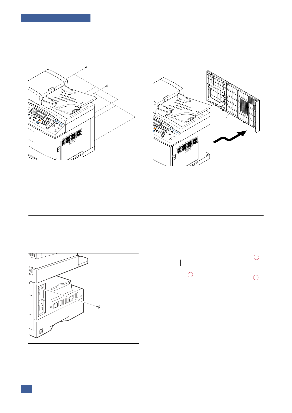
5.2 Rear Cover
1. Remove the six screws securing the Rear Cover. 2. Separate the rear cover from the base frame and
Scanner Ass'y .
5.3 Removing the LIU PBA
1. Before you remove the Scanner Ass'y, you should
remove:
- Rear Cover (see page 5-1)
2. Remove the screw securing the Cover Panel MFP
3. Remove 2 screws securing the PBA and disconnect
the LIU harness. Release the plastic supporting clip
and remove the LIU
ScrewScrew
ScrewScrew
Supporting ClipSupporting Clip
LIU HarnessLIU Harness
Rear Cover
Page 3
Precautions
Service Manual
5-3
Samsung Electronics
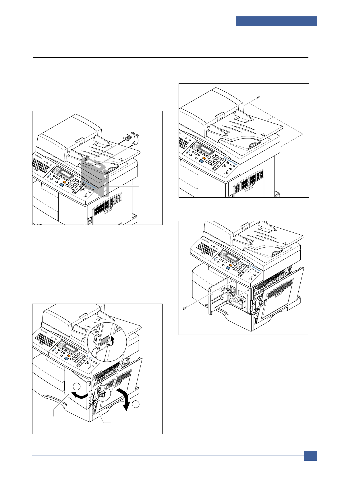
5.4 Scanner Ass’y
1. Before you remove the Scanner Ass'y, you should
remove:
- Rear Cover (see page 5-2)
- LIU PBA (see page 5-2)
2. Unplug the DADF harness connector and CCD cable.
Notice : When removing the CCD flat cable pull firmly
taking care not to bend or crack the cable.
3. The side and front covers are interlocked. Open the
side door before opening the front door. When closing
the doors the front door must be closed before the
side door.
Open the front and side doors to gain access to the
screws in the following steps.
4. Remove the three screws, as shown below. Also
remove the single screw securing 2 ground cables.
5. Remove two screws.
Main
Shield
2
1
Front Cover
Side Cover Ass'y
Page 4
Service Manual
Precautions
5-4
Samsung Electronics
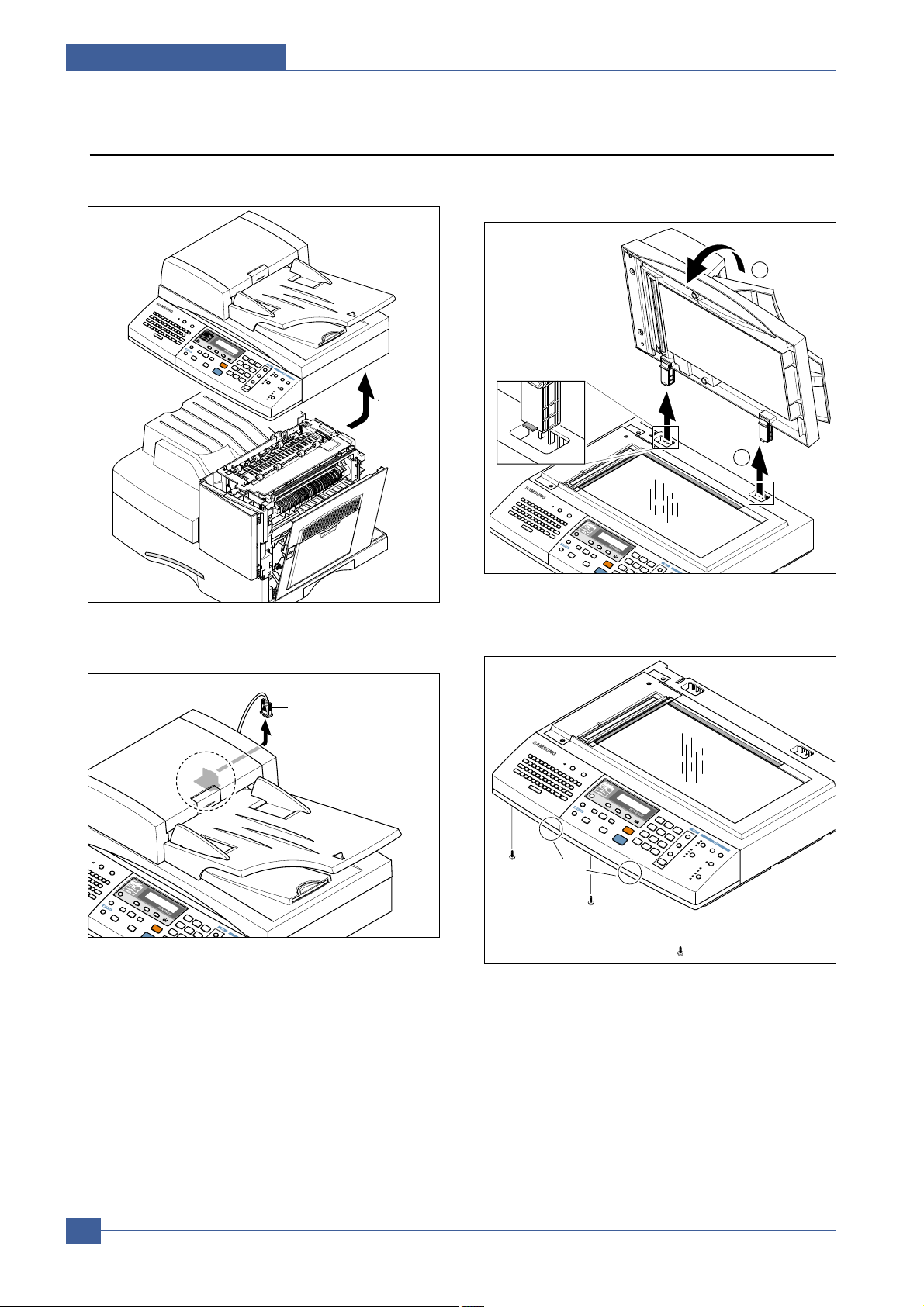
6. Pull up the Scanner Ass'y in the direction of arrow.
7. Remove the DADF Main Cable.
8. Open the DADF Ass’y in the direction of arrow. Pull
the DADF Ass'y upward and remove it.
9. Remove the three screws securing the Platen Ass'y.
Scanner Ass'y
2
1
DADF Main Cable
Clips
Page 5
Precautions
Service Manual
5-5
Samsung Electronics
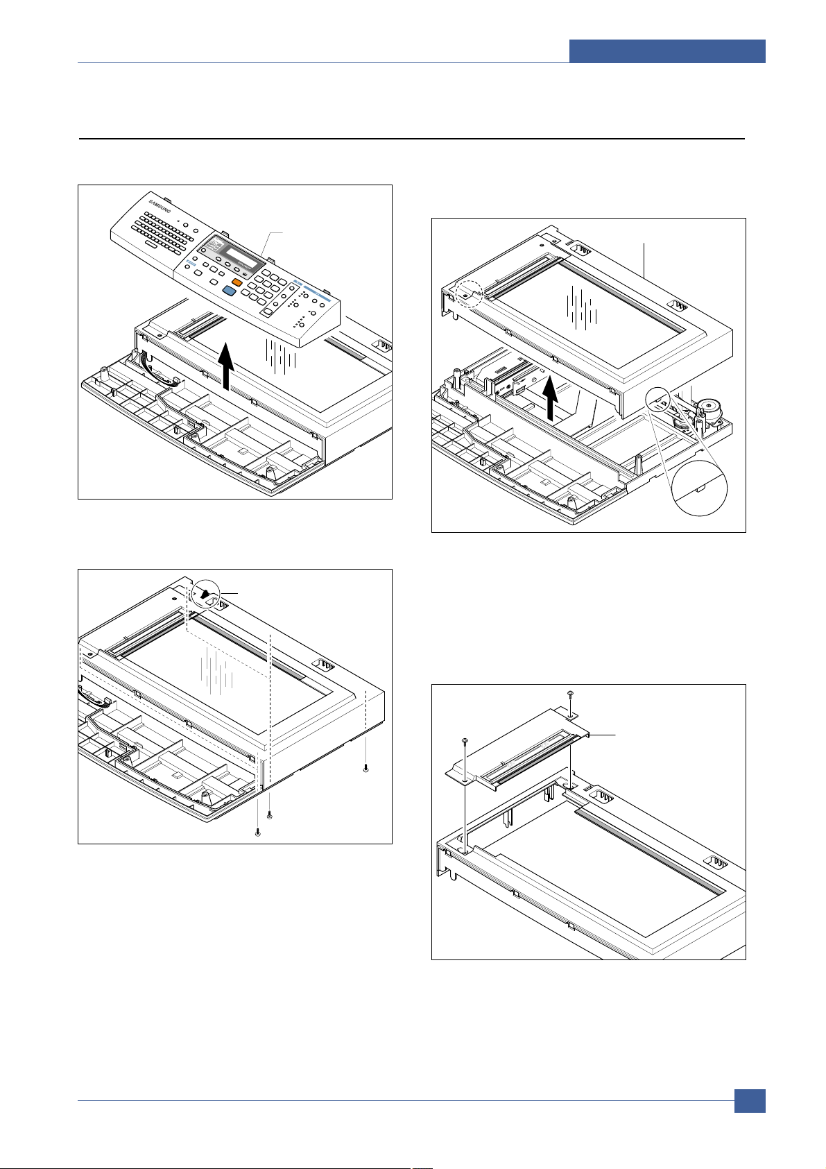
10. Pull the OPE Ass'y and unplug the one connector.
11. Remove the five screws securing the Platen Ass'y.
12. Release 2 clips (1 each side) to release the Scan
Upper Ass'y securing the glass and remove it. Take
care to ensure that the DADF connector is clear.
Notice : When reassembling the Scan Upper take care
to ensure that the Lever Sensor is free to
operate
13. Remove the two screws to remove the Dummy
Upper Ass'y .
Notice : Dust or other foreign matter can cause the
module to jam or image quality to deteriorate.
Only open the scanner in a clean environment
and ensure all parts are clean when
reassembling the scanner.
OPE Ass'y
Lever Sensor
Scan Upper Ass'y
Hook
Dummy Upper Ass'y
Page 6
Service Manual
Precautions
5-6
Samsung Electronics
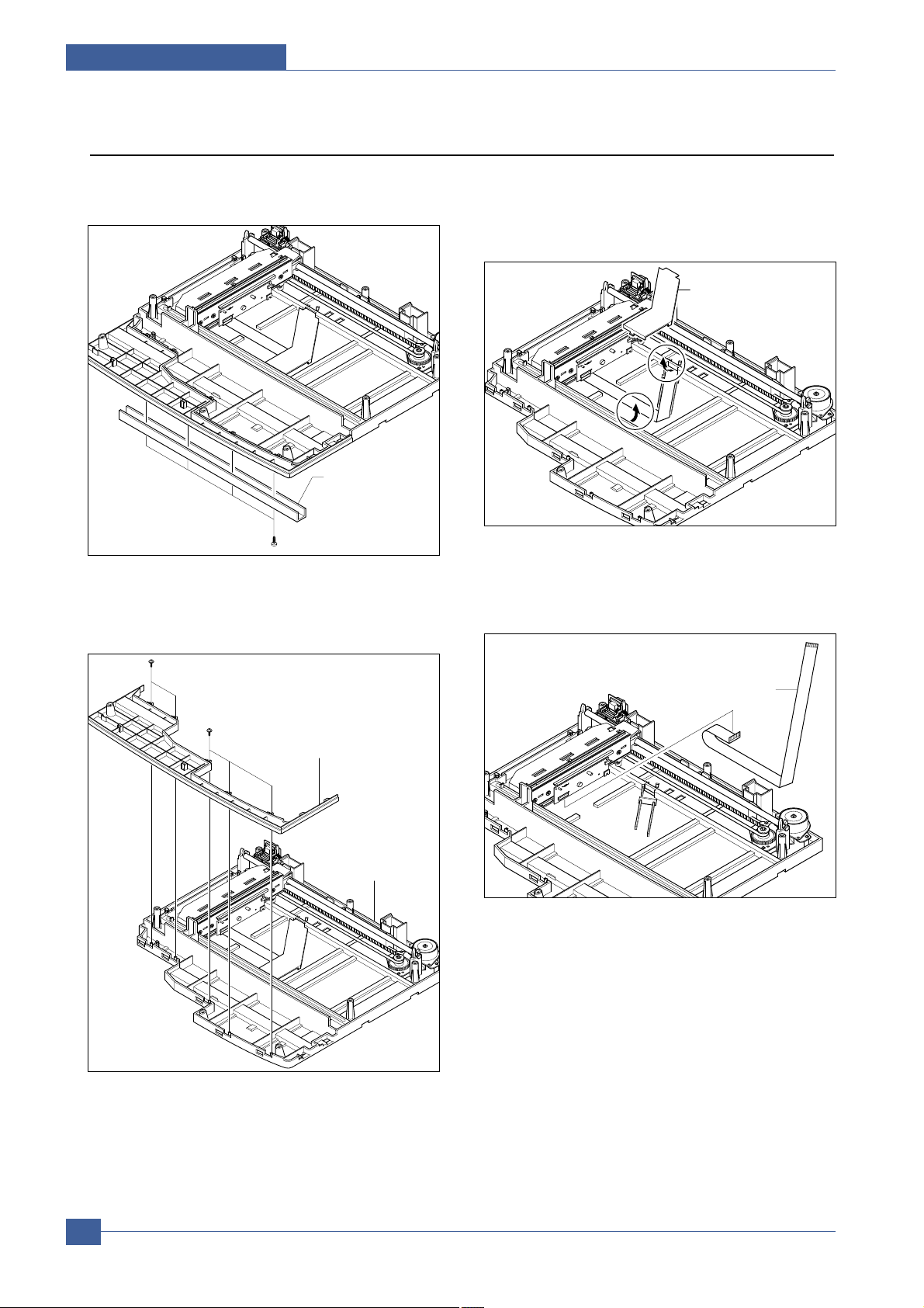
14. Remove four screws to release the Channel Base
Frame.
15. Remove the five screws securing the Cover Dummy
Lower and remove it.
16. Remove the CCD cable cover by flexing and
releasing the front clip. Slide the scan module to a
position half way along the scanner bed and raise it
to a vertical position. Disconnect the CCD cable
17. Release the belt from the underside of the scanner
module. Unclip the Shaft CCD and take out the
Scanner Module.
Channel
Base Frame
CCD Cable Cover
Cover Dummy Lower
Cover Scan Lower
CCD Cable
Page 7
Precautions
Service Manual
5-7
Samsung Electronics
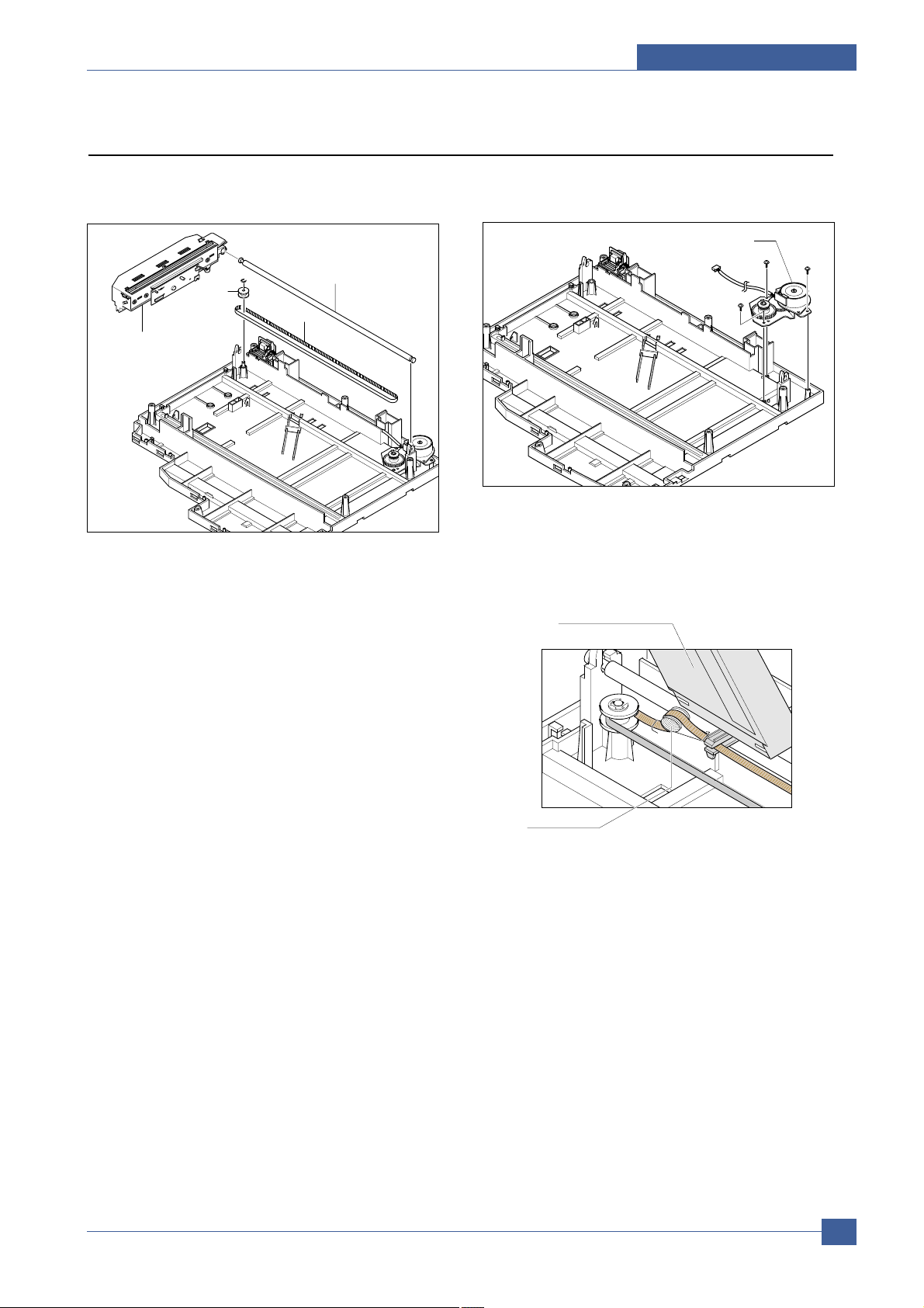
18. Disconnect the motor harness. Remove three
screws and take out the Motor Bracket.
19. Remove the OPE Harness from the Platen PBA.
Remove two screws and take out the Platen PBA.
Notice : Take care when reassembling the scanner
module to the belt. The CCD Module should be
located just to the right of the belt tension spring
as shown below.
Motor Bracket
Shaft CCD
Pully
Belt
Scanner Module
Scanner Module
Spring Belt
Page 8
Service Manual
Precautions
5-8
Samsung Electronics
5.5 DADF Ass’y
1. Before you remove the DADF Ass'y, you should
remove:
- Rear Cover (see page 5-2)
- LIU PBA (see page 5-2)
- Scanner Ass'y (see page 5-3)
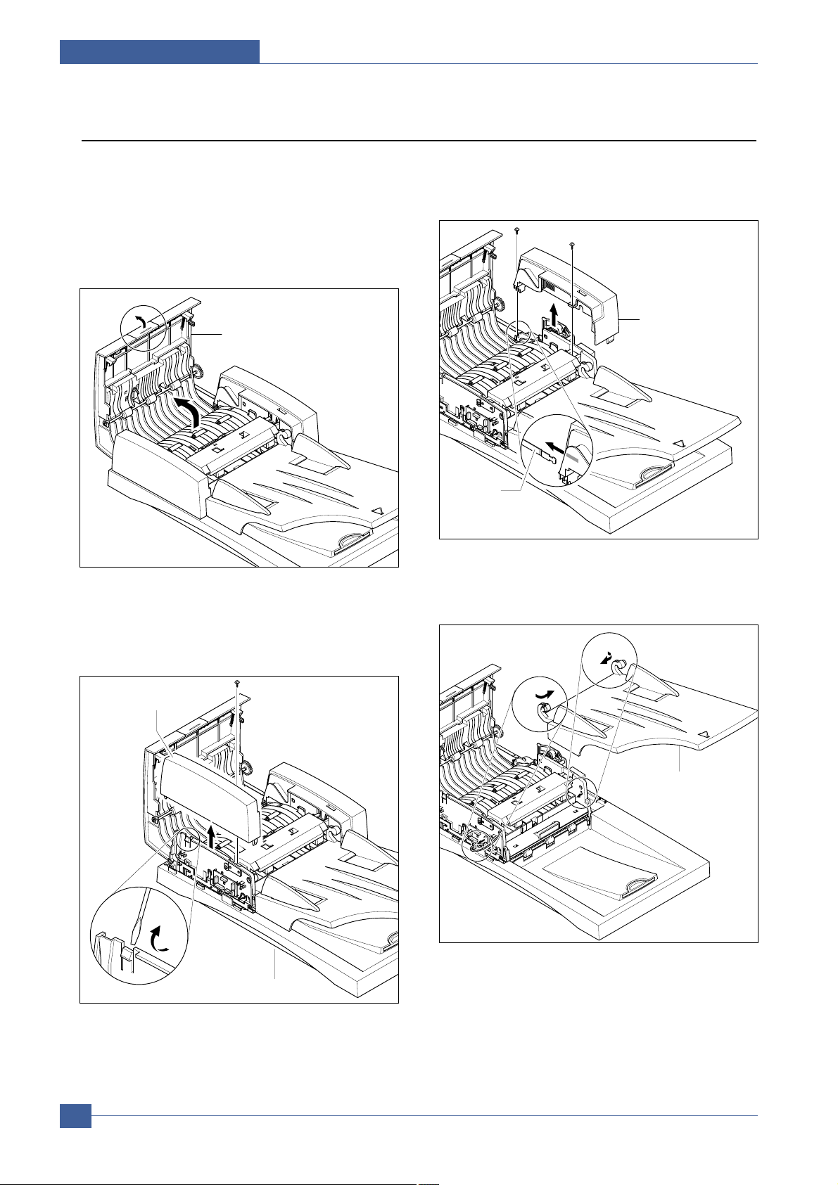
2. Open the Open Cover Ass’y
3. Remove the one screw securing the COVER-M-FRONT
and unlatch the COVER-M-FRONT using a flat-blade
screwdriver, as shown below. Then pull the COVER-MFRONT upward and remove it.
4. Remove the two screws securing the COVER-M-REAR
and release the stopper. Then pull the COVER-M-REAR
upward and remove it.
5. Remove the TX Stacker
Open Cover Ass'y
COVER-M-REAR
Stopper
COVER-M-FRONT
Platen Cover Ass’y
TX Stacker Ass’y
Page 9

Precautions
Service Manual
5-9
Samsung Electronics
6. Lift the Guide Duplex Ass’y at the front hinge. It may
be necessary to gently flex the plastic frame to
release the hinge. Take out the Guide Duplex Ass'y,
as shown below.
7. Remove the two screws securing the Support Pickup
Ass'y. Look under the edge of the Support Pickup
Ass’y and release the spring from the Pickup Ass’y.
Then remove the Support Pickup Ass’y, as shown
below.
8. Unplug the one connector and remove the circlip on
the end of the shaft. Remove the Clutch. Remove 2
further circlips and bushes then take out the Pickup
Ass'y, as shown below.
9. Unplug The Gate Sensor connector and remove one
screw securing the ground cable.
Guide Duplex Ass'y
Pickup Ass’y
E-Ring
Clutch
Circlips
DADF SUB Ass’y
SpringRoller Holder
Support Pickup Ass’y
Gate Sensor
Page 10

Service Manual
Precautions
5-10
Samsung Electronics
10. Remove the four screws securing the Scan Main
Ass'y and remove it.
11. Unplug the Open Cover Sensor connector and
remove the Open Cover Ass'y in the direction of
arrow. Then release the harness, as shown below.
12. Open the Cover Exit Ass'y and unplug the two connectors.
13. Remove the three screws securing the Guide Pickup
Ass'y and remove it.
DADF Sub Ass'y
Platen Ass'y
Open Cover Ass’y
Cover Exit Ass'y
Guide Pickup Ass’y
Width Sensor
Doc Sensor
Open Cover
Sensor
1
2
Page 11

Precautions
Service Manual
5-11
Samsung Electronics
14. Remove the five screws securing the Guide-DuplexInner and Guide-Duplex-Lower covers. Then remove
them.
15. Remove the three screws securing the Cover Gear
and remove it, as shown below.
16. Unplug the one connector. Then remove the five
screws securing the DADF Motor Ass'y and remove
it, as shown below.
17. Unplug the one connector and three screws securing
the Duplex Motor Ass'y and remove it.
Guide Duplex
Lower
Guide Duplex Inner
DADF Motor Ass’y
Duplex Motor Ass'y
Cover Gear
Page 12

Service Manual
Precautions
5-12
Samsung Electronics
5.6 OPE Ass'y (SCX-6320F shown, SCX6220 is similar)
1. Before you remove the OPE Ass'y, you should
remove:
- Rear Cover (see page 5-2)
- LIU PBA (see page 5-2)
- Scanner Ass'y (see page 5-3)
2. Unplug the FPC Cable from the OPE Main PBA.
Remove two screws securing the OPE Sub PBAand
remove it.
3. Remove ten screws securing the OPE Main PBAand
the LCD Module from the OPE Cover
4. Remove the Contact Rubbers from the unit.
5. Remove the Key Pad from the unit.
OPE Sub
PBA
FPC Cable
Contact Rubber
Key Pad
OPE
Main PBA
Page 13

Precautions
Service Manual
5-13
Samsung Electronics
6. Pull up the E-MAIL UNIT.
7. Remove the five screws securing the E-MAIL Option
PBA and remove it.
8. Remove the Key Plate from the unit.
9. Remove the Email Rubber and Key Pad from the unit.
E-MAIL UNIT
Key Plate
COVER-M-EMAIL
E-MAIL PBA
E-mail Rubber
Key Pad
Page 14

Service Manual
Precautions
5-14
Samsung Electronics
5.7 Side Cover Ass’y
1. Remove two screws to release the Stopper securing
the Side Cover to the Main Frame.
2. Lift hinge to release it and then slide the Side
Cover Ass’y towards the front to release hinge
and lift out the cover.
* MP-Tray
1. Pull firmly on both hinges to release them.
2. Taking care not to damage the Tray Links position the
Tray Case so that the Tray Links are at 45° and
release the Tray Links from the slot in the Tray Case.
Stopper
Hook
1
1
2
1
1
MP Tray
2
2
Tray-Case
3
1
1
Tray Link
Side Cover Ass'y
Page 15

Precautions
Service Manual
5-15
Samsung Electronics
* Duplex Ass’y
1. Release 4 clips (2 each side – 1 black and 1 white).
Then lift the Duplex Ass’y away from the Side Cover.
* Transfer Roller Ass’y
1. Release the colored plastic bushes at each end of the
Transfer Roller and lift the roller out, as shown below.
Duplex Ass’y
Page 16

Service Manual
Precautions
5-16
Samsung Electronics
5.8 Fuser Ass’y
1. Before you remove the Fuser Ass'y, you should be
power off and remove:
- Rear Cover (see page 5-2)
- Side Cover Ass'y (see page 5-13)
2. Remove the one screw and take out the Cover Sheet
Connector.
3. Unplug the one connector.
4. Open the Front Door and then remove the three
screws and take out the Fuser Ass'y.
5. Remove the two screws and take out the Thermostat.
Cover Sheet
Connector
Thermostat
Page 17

Precautions
Service Manual
5-17
Samsung Electronics
5.9 Exit Ass'y
1. Before you remove Exit Ass'y, you should remove:
- Rear Cover (see page 5-2)
- LIU PBA (see page 5-2)
- Scanner Ass'y (see page 5-3)
2. Remove three screws, and then untie the harness
from the Exit Upper. Unplug one connector from the
Main PBA and unlatch the Dummy Base Frame using
a flat blade screwdriver, as shown below.
3. Lift the exit ass'y and remove it.
5.10 Cover Paper Exit Ass'y
1. Before you remove the Cover Paper Exit Ass'y, you
should remove:
- Rear Cover (see page 5-2)
- LIU PBA (see page 5-2)
- Scanner Ass'y (see page 5-3)
2. Remove two screws and Cover Paper Exit Ass'y, as
shown below.
Cover Paper Exit Ass’y
Page 18

Service Manual
Precautions
5-18
Samsung Electronics
5.11 Drive Ass’y
1. Before you remove the Drive Ass'y, you should
remove:
- Rear Cover (see page 5-2)
2. Unplug the two connectors.
(Main Motor : 10 pin, Duplex Motor : 4 pin)
3. Disconnect the fan harness from the Main PBA.
Remove one screw and take out the Fan and Dust
Fan.
4. Remove four screws (2 screws securing ground wires
and 1 screw securing the Zener PBA) and take out
the Drive Ass'y. taking care not to damage the Zener
PBA.
Fan
Dust Fan
Driver Ass'y
Page 19

Precautions
Service Manual
5-19
Samsung Electronics
5.12 SMPS
1. Before you remove the LSU, you should remove:
- Rear Cover (see page 5-2)
- LIU PBA (see page 5-2)
- Scanner Ass’y (see page 5-3)
- Cover Paper Exit Ass’y(see page 5-17)
2. Remove three screws and take out the Shield SMPS
Upper.
3. Unplug the all connectors.
4. Remove the SMPS, as shown below.
SMPS
Page 20

Service Manual
Precautions
5-20
Samsung Electronics
5.13 LSU (Laser Scaning Unit)
1. Before you remove the LSU, you should remove:
- Rear Cover (see page 5-2)
- LIU PBA (see page 5-2)
- Scanner Ass’y (see page 5-3)
- Cover Paper Exit Ass’y (see page 5-17)
2. Unplug the two connectors.
3. Remove the three screws and take out the LSU.
To Main PBA
To LSU
5.14 Cover Exit Rear
1. Before you remove the Cover Exit Rear , you should
remove:
- Rear Cover (see page 5-2)
- LIU PBA (see page 5-2)
- Scanner Ass’y (see page 5-3)
- Exit Ass'y (see page 5-17)
- Cover Paper Exit Ass’y(see page 5-17)
- SMPS (see page 5-19)
2. Remove the one screw and take out the Panel
Connect MPF.
3. Remove the one screw and Cover Exit Rear, as
shown below.
LSU
Cover Exit Rear
Page 21

Precautions
Service Manual
5-21
Samsung Electronics
5.15 Main Frame Ass’y
1. Before you remove the LSU, you should remove:
- Rear Cover (see page 5-2)
- LIU PBA (see page 5-2)
- Scanner Ass’y (see page 5-3)
- Side Cover Ass'y (see page 5-13)
- Fuser (see page 5-15)
- Exit Ass’y (see page 5-17)
- Cover Paper Exit Ass’y(see page 5-17)
- SMPS (see page 5-19)
- LSU (see page 5-20)
2. Remove 3 screws located inside the Dummy Base
Frame and 1 screw securing the Dummy Base Frame
to the Channel Base Frame. Disconnect the Counter
harness. Lift out the Dummy Base Frame and the jam
release mechanism.
3. Remove the Lock Deve, and then remove one screw
and the Cover Motor Bracket.
4. Unplug the all connectors.
5. Remove the seven screws and take out the Main
Frame Ass'y .
Dummy Base Frame
Cam Jam Remove
Front Cover
Main Frame Ass’y
Lock Deve
Cover Motor Bracket
Page 22

Service Manual
Precautions
5-22
Samsung Electronics
5.16 MP Ass’y
1. Before you remove the MPAss’y, you should remove:
- Rear Cover (see page 5-2)
- LIU PBA (see page 5-2)
- Side Cover Ass'y (see page 5-13)
2. Unplug the two connectors.
3. Remove the one screw and take out the Dummy
Cover.
4. remove the three screws.
5. Release two hooks underneath the frame. Pull the MP
Ass'y upward and remove it.
MP Ass'y
Dummy Cover
1
Page 23

Precautions
Service Manual
5-23
Samsung Electronics
5.17 Feed Ass’y
1. Before you remove the Feed Ass’y, you should
remove:
- Rear Cover (see page 5-2)
- LIU PBA (see page 5-2)
- Scanner Ass’y (see page 5-3)
- Side Cover Ass'y (see page 5-13)
- Exit Ass’y (see page 5-17)
- Cover Paper Exit Ass’y(see page 5-17)
- LSU (see page 5-20)
- Main Frame Ass’y (see page 5-21)
- MPAss’y(see page 5-22)
2. Remove the three screws.
3. Pull the Feed Ass'y upward and remove it.
MP Ass'y
Feed Ass'y
Page 24

Service Manual
Precautions
5-24
Samsung Electronics
5.18 Pick Up Ass’y
1. Before you remove the Pick Up Ass’y, you should
remove:
- Rear Cover (see page 5-2)
- Drive Ass'y (see page 5-14)
2. Remove three connector and take out the pick up
gear.
3. Remove the two screws and take out the Cassette
Rail.
4. Unlatch the shaft bush.
5. Remove the three screws and one ground screw
shown below. Release the paper Pickup Roller bush
(white plastic clip) and take out the Pick Up Ass'y, as
shown below.
To Main PBA
shaft bushshaft bush
Cassette Rail
Guide Paper Out
Pick-up Ass’y
IPR-Gnd Input
Ground Screw
Page 25

Precautions
Service Manual
5-25
Samsung Electronics
5.19 Main PBA
To remove the Main PBA without major disassembly
1. Before you remove the Main PBA, you should
remove:
- Rear Cover (see page 5-1)
- LIU PBA (see page 5.??)
Goto Step 4
In order to remove the Shield Main Lower you must
also remove:
- Scanner Ass'y (see page 5-2)
- Cover Paper Exit Ass'y(see page 5-16)
- SMPS (see page 5-18)
2. Remove the two frame screws and 2 ground wire
screws. Take out the Shield Main taking care to ease
the power socket from the LH frame.
3. Remove the 2 screws securing the parallel connector
and 4 screws holding the Main PBAto the Shield
Main Lower. Take out the Main PBAfrom the Shield
Main Lower.
4. If fitted release the plastic support securing the NPC
PBA to the Main PBA
Shield Main Lower
Main PBA
Shield Main Lower
Main PBA
NPC PBA
Page 26

Service Manual
Precautions
5-26
Samsung Electronics
MEMO
 Loading...