

Page 1
Service Manual
■ 33 ppm(A4) Network-ready MFP
■ Toner cartridge
: Initial : 4K / Sales : 4K,10K
■ Paper handling
: 500 sheets Standard cassette
: 500 sheets Optional cassette
: 50 sheets DADF
The keynote of Product
DIGITAL LASER MFP
SCX-5835NX_5935NX Series
■ 160GB HDD
■ High Performance CCDM
■ Easy to install ( CRU & Option )
■ Color Graphic Touch-Screen LCD (7”)
■ Low Cost per Page
■ Direct USB
Page 2
GSPN (Global Service Partner Network)
North America : service.samsungportal.com
Latin America : latin.samsungportal.com
CIS : cis.samsungportal.com
Europe : europe.samsungportal.com
China : china.samsungportal.com
Asia : asia.samsungportal.com
Mideast & Africa : mea.samsungportal.com
ⓒ
Samsung Electronics Co.,Ltd. June. 2010
Printed in Korea.
VERSION NO. : 1.00 CODE : 5835-N0000E
Page 3

chapter 1 Precautions
1.1 Safety Warning …………………………………………………… 1-1
1.2 Caution for safety ………………………………………………… 1-2
1.3 ESD Precautions ………………………………………………… 1-5
1.4 Super Capacitor or Lithium Battery Precautions ……………… 1-5
chapter 2 Product Overview
2.1 Product Overview ………………………………………………… 2-1
2.1.1 Product Summary …………………………………………… 5-1
Contents
2.1.2 Specications ………………………………………………… 2-2
2.1.3 Model Comparison ………………………………………… 2-11
2.2 System Overview ………………………………………………… 2-14
2.2.1 System Conguration ……………………………………… 2-15
2.2.2 Hardware Conguration …………………………………… 2-15
2.2.3 Mechanic Conguration …………………………………… 2-22
chapter 3 Disassembly and Reassembly
3.1 Disassembly and Reassemblyons on Disassembly ………… 3-1
3.2 Maintenance Parts ……………………………………………… 3-2
3.3 General Disassembly …………………………………………… 3-3
3.3.1 Fuser Unit …………………………………………………… 3-3
3.3.2 DADF Pick up unit and rubber pad ……………………… 3-3
3.3.3 Pick up roller ………………………………………………… 3-4
3.3.4 Transfer roller ……………………………………………… 3-4
3.3.5 Cover ………………………………………………………… 3-5
3.3.6 DADF Board ………………………………………………… 3-7
3.3.7 Scan Assy …………………………………………………… 3-8
3.3.8 Middle Cover ………………………………………………… 3-10
Page 4

3.3.9 HDD/ Main PBA/ Fax board ……………………………… 3-11
3.3.10 SMPS board ……………………………………………… 3-12
3.3.11 Main Drive unit ……………………………………………… 3-12
3.3.12 HVPS board ………………………………………………… 3-13
3.3.13 LSU Unit …………………………………………………… 3-13
chapter 4 Alignment and Troubleshooting
4.1 Alignment and Adjustments ……………………………………… 4-1
4.1.1 Paper path …………………………………………………… 4-1
4.1.2 Clearing Paper Jams ……………………………………… 4-2
Contents
4.1.3 Abnormal Image Printing and Defective Roller …………… 4-13
4.1.4 Control Panel overview …………………………………… 4-15
4.1.5 Understanding The Status LED …………………………… 4-18
4.1.6 Menu overview ……………………………………………… 4-19
4.1.7 Firmware Upgrade ………………………………………… 4-31
4.1.8 Diagnostics …………………………………………………… 4-35
4.2 Troubleshooting…………………………………………………… 4-59
4.2.1 Procedure of Checking the Symptoms …………………… 4-59
4.2.2 Error Message ……………………………………………… 4-60
4.2.3 Solution ……………………………………………………… 4-64
chapter 5 System Diagram
5.1 Block Diagram …………………………………………………… 5-1
5.2 Connection Diagram……………………………………………… 5-3
chapter 6 Reference Information
6.1 Tool for Troubleshooting ………………………………………… 6-1
6.2 Acronyms and Abbreviations …………………………………… 6-2
Page 5

6.2.1 Acronyms …………………………………………………… 6-2
6.2.2 Service Parts ………………………………………………… 6-4
6.3 The Sample Pattern for the Test ………………………………… 6-8
6.4 Selecting a location ……………………………………………… 6-9
attached Exploded Views & Parts List
Contents
Page 6
Precautions
1. Precautions
In order to prevent accidents and damages to the equipment please read the precautions listed below
carefully before servicing the product and follow them closely.
1.1 Safety warning
(1) Only to be serviced by a factory trained service technician.
High voltages and lasers inside this product are dangerous. This product should only be serviced by a
factory trained service technician.
(2) Use only Samsung replacement parts.
There are no user serviceable parts inside the product. Do not make any unauthorized changes or
additions to the product as these could cause the product to malfunctions and create an electric shocks
or re hazards.
(3) Laser Safety Statement
The product is certied in the U.S. to conform to the requirements of DHHS 21 CFR, chapter 1
Subchapter J for Class 1(1) laser products, and elsewhere, it is certied as a Class I laser product conforming to the requirements of IEC 825. Class I laser products are not considered to be hazardous. The
laser system and product are designed so there is never any human access to laser radiation above a
Class I level during normal operation, user maintenance, or prescribed service condition.
Warning >> Never operate or service the product with the protective cover removed from Laser/Scanner
assembly. The reected beam, although invisible, can damage your eyes.
When using this product, these basic safety pre-cautions should always be followed to reduce
risk of re, electric shock, and personal injury.
Service Manual
1-1
Samsung Electronics
Page 7

Precautions
Service Manual
1-2
Samsung Electronics
1.2 Caution for safety
1.2.1 Toxic material
This product contains toxic materials that could cause illness if ingested.
(1) If the LCD control panel is damaged, it is possible for the liquid inside to leak. This liquid is toxic.
Contact with the skin should be avoided. Wash any splashes from eyes or skin immediately and contact
your doctor. If the liquid gets into the mouth or is swallowed, see a doctor immediately.
(2) Please keep imaging unit and toner cartridge away from children. The toner powder contained in the
imaging unit and toner cartridge may be harmful, and if swallowed, you should contact a doctor.
1.2.2 Electric shock and re safety precautions
Failure to follow the following instructions could cause electric shock or potentially cause a re.
(1) Use only the correct voltage, failure to do so could damage the product and potentially cause a re or
electric shock.
(2) Use only the power cable supplied with the product. Use of an incorrectly specied cable could cause the
cable to overheat and potentially cause a re.
(3) Do not overload the power socket, this could lead to overheating of the cables inside the wall and could
lead to a re, and/or cause your ceiling or lamp lights to icker.
(4) Do not allow water or other liquids to spill into the product, this can cause electric shock. Do not allow
paper clips, pins or other foreign objects to fall into the product, these could cause a short circuit leading
to an electric shock or re hazard.
(5) Never touch the plugs on either end of the power cable with wet hands, this can cause electric shock.
When servicing the product, remove the power plug from the wall socket.
(6) Use caution when inserting or removing the power connector. When removing the power connector, grip it
rmly and pull. The power connector must be inserted completely, otherwise a poor contact could cause
overheating possibly leading to a re.
(7) Take care of the power cable. Do not allow it to become twisted, bent sharply around corners or wise
damaged. Do not place objects on top of the power cable. If the power cable is damaged it could overheat
and cause a re. Exposed cables could cause an electric shock. Replace the damaged power cable
immediately, do not reuse or repair the damaged cable. Some chemicals can attack the coating on the
power cable, weakening the cover or exposing cables causing re and shock risks.
(8) Ensure that the power sockets and plugs are not cracked or broken in any way. Any such defects should
be repaired immediately. Take care not to cut or damage the power cable or plugs when moving the
machine.
(9) Use caution during thunder or lightning storms. Samsung recommends that this machine be disconnected
from the power source when such weather conditions are expected. Do not touch the machine or the
power cord if it is still connected to the wall socket in these weather conditions.
(10) Avoid damp or dusty areas, install the product in a clean well ventilated location. Do not position the
machine near a humidier or in front of an air conditioner. Moisture and dust built up inside the machine
can lead to overheating and cause a re or cause parts to rust.
(11) Do not position the product in direct sunlight. This will cause the temperature inside the product to rise
possibly leading to the product failing to work properly and in extreme conditions could lead to a re.
(12) Do not insert any metal objects into the machine through the ventilator fan or other part of the casing, it
could make contact with a high voltage conductor inside the machine and cause an electric shock.
Page 8

Precautions
Service Manual
1-3
Samsung Electronics
1.2.3 Handling precautions
The following instructions are for your own personal safety to avoid injury and so as not to damage the
product.
(1) Ensure the product is installed on a level surface, capable of supporting its weight. Failure to do so could
cause copy quality problems, and/or the product to tip or fall.
(2) The product contains many rollers, gears and fans. Take great care to ensure that you do not catch your
ngers, hair or clothing in any of these rotating devices.
(3) Do not place any small metal objects, containers of water, chemicals or other liquids close to the product
which if spilled could get into the machine and cause damage or a shock or re hazard.
(4) Do not install the machine in areas with high dust or moisture levels, beside on open window or close to a
humidier or heater. Damage could be caused to the product in such areas.
(5) Do not place candles, burning cigarettes, etc on the product, These could cause a re.
1.2.4 Assembly / Disassembly precautions
Replace parts carefully and always use Samsung parts. Take care to note the exact location of parts and also
cable routing before dismantling any part of the machine. Ensure all parts and cables are replaced correctly.
Please carry out the following procedures before dismantling the product or replacing any parts.
(1) Check the contents of the machine memory and make a note of any user settings. These will be erased if
the main board or network card is replaced.
(2) Ensure that power is disconnected before servicing or replacing any electrical parts.
(3) Disconnect interface cables and power cables.
(4) Only use approved spare parts. Ensure that part number, product name, any voltage, current or
temperature rating are correct.
(5) When removing or re-tting any parts do not use excessive force, especially when tting screws into
plastic.
(6) Take care not to drop any small parts into the machine.
(7) Handling of the OPC Drum
- The OPC Drum can be irreparably damaged if it exposed to light.
Take care not to expose the OPC Drum either to direct sunlight or to uorescent or incandescent room
lighting. Exposure for as little as 5 minutes can damage the surface of the photoconductive properties
and will result in print quality degradation. Take extra care when servicing the product. Remove the OPC
Drum and store it in a black bag or other lightproof container. Take care when working with the Covers
(especially the top cover) open as light is admitted to the OPC area and can damage the OPC Drum.
- Take care not to scratch the green surface of OPC Drum Unit.
If the green surface of the Drum Cartridge is scratched or touched the print quality will be compromised.
Page 9

Precautions
Service Manual
1-4
Samsung Electronics
1.2.5 Disregarding this warning may cause bodily injury
(1) Be careful with the high temperature part.
The fuser unit works at a high temperature. Use caution when working on the printer. Wait for the fuser to
cool down before disassembly.
(2) Do not put nger or hair into the rotating parts.
When operating a printer, do not put hand or hair into the rotating parts (Paper feeding entrance, motor,
fan, etc.). If do, you can get harm.
(3) When you move the printer
- When transporting/installing the equipment be sure to hold the positions as shown in the reference
chapter.
The equipment is quite heavy and weighs approximately 23.1Kg (including consumables), therefore pay
full attention when handling it.
- Be sure not to hold the movable parts or units (e.g. the control panel, DADF) when transporting the
equipment.
- Be sure to use a dedicated outlet with 110V/220Vpower input.
- The equipment must be grounded for safety.
- Select a suitable place for installation. Avoid excessive heat, high humidity, dust, vibration and direct
sunlight.
- Provide proper ventilation since the equipment emits a slight amount of ozone.
- To insure adequate working space for the copying operation, keep a minimum clearance of 10cm (3.9”
on the left, 10 cm (3.9”) on the right and 10 cm (3.9”) on the rear.
- The equipment shall be installed near the socket outlet and shall be accessible.
- Be sure to x and plug in the power cable securely after the installation so that no one trips over it.
Page 10

Precautions
Service Manual
1-5
Samsung Electronics
1.3 ESD precautions
Certain semiconductor devices can be easily damaged by static electricity. Such components are commonly
called “Electrostatically Sensitive (ES) Devices” or ESDs. Examples of typical ESDs are: integrated
circuits,some eld effect transistors, and semiconductor “chip” components.
The techniques outlined below should be followed to help reduce the incidence of component damage
caused by static electricity.
Caution >>Be sure no power is applied to the chassis or circuit, and observe all other safety precautions.
1. Immediately before handling a semiconductor component or semiconductor-equipped assembly, drain
off any electrostatic charge on your body by touching a known earth ground. Alternatively, employ a
commercially available wrist strap device, which should be removed for your personal safety reasons prior
to applying power to the unit under test.
2. After removing an electrical assembly equipped with ESDs, place the assembly on a conductive surface,
such as aluminum or copper foil, or conductive foam, to prevent electrostatic charge buildup in the vicinity
of the assembly.
3. Use only a grounded tip soldering iron to solder or desolder ESDs.
4. Use only an “anti-static” solder removal device. Some solder removal devices not classied as “anti-static”
can generate electrical charges sufcient to damage ESDs.
5. Do not use Freon-propelled chemicals. When sprayed, these can generate electrical charges sufcient to
damage ESDs.
6. Do not remove a replacement ESD from its protective packaging until immediately before installing it.
Most replacement ESDs are packaged with all leads shorted together by conductive foam, aluminum foil,
or a comparable conductive material.
7. Immediately before removing the protective shorting material from the leads of a replacement ESD, touch
the protective material to the chassis or circuit assembly into which the device will be installed.
8. Maintain continuous electrical contact between the ESD and the assembly into which it will be installed,
until completely plugged or soldered into the circuit.
9. Minimize bodily motions when handling unpackaged replacement ESDs. Normal motions, such as
the brushing together of clothing fabric and lifting one’s foot from a carpeted oor, can generate static
electricity sufcient to damage an ESD.
1.4 Super Capacitor or Lithium Battery Precautions
1. Exercise caution when replacing a super capacitor or Lithium battery. There could be a danger of explosion
and subsequent operator injury and/or equipment damage if incorrectly installed.
2. Be sure to replace the battery with the same or equivalent type recommended by the manufacturer.
3. Super capacitor or Lithium batteries contain toxic substances and should not be opened, crushed, or
burned for disposal.
4. Dispose of used batteries according to the manufacture? instructions.
Page 11
Product spec and feature
2. Product spec and feature
2.1 Product Overview
2.1.1 Product Summary
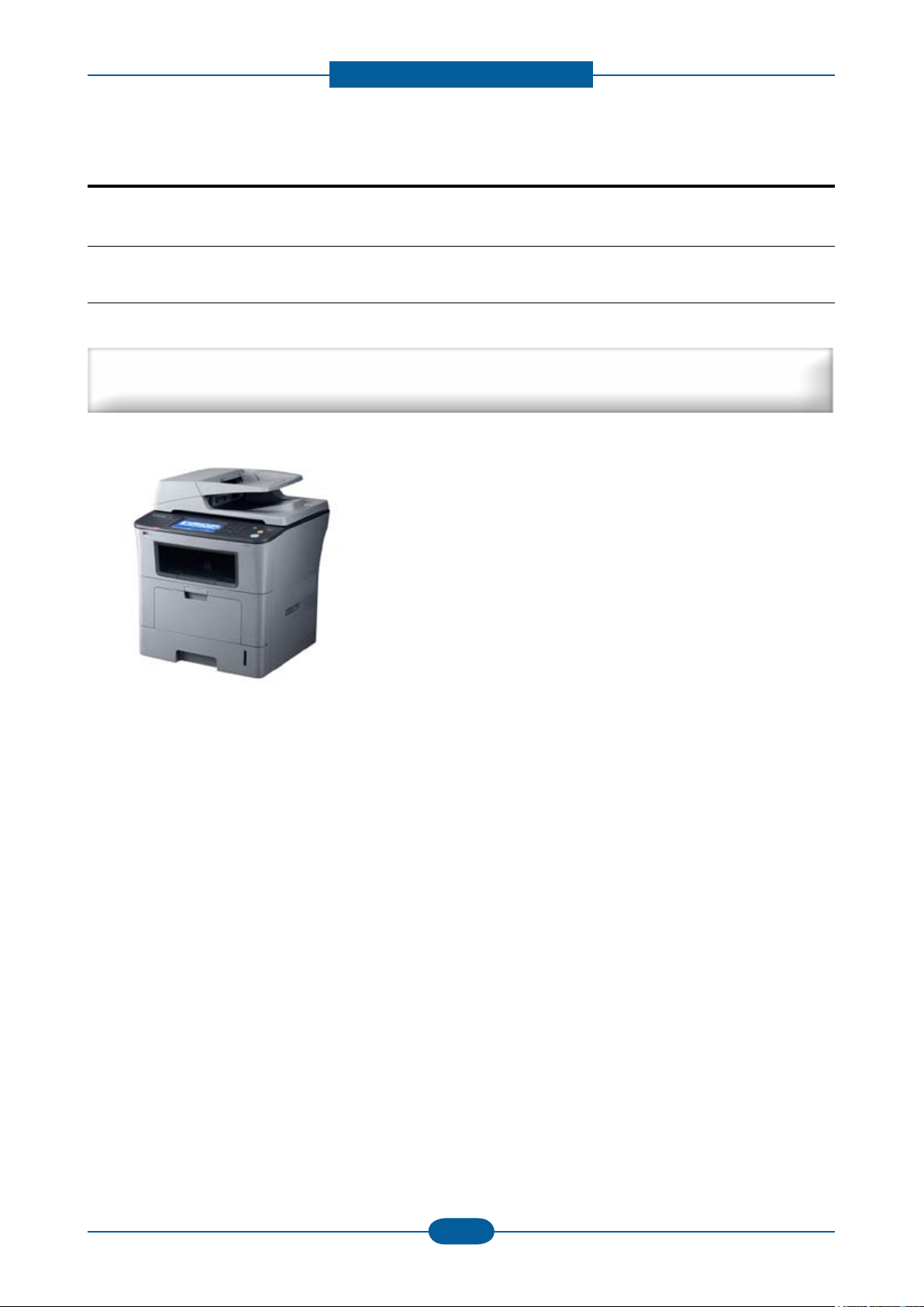
Premium LMFP with High Reliability and Quality
Target user : 10 Persons N/W Small Workgroup
■ 33 ppm(A4) Network-ready MFP
■ Toner cartridge
: Initial : 4K / Sales : 4K,10K
■ Paper handling
: 500 sheets Standard cassette
: 500 sheets Optional cassette
: 50 sheets DADF
■ 160GB HDD
■ High Performance CCDM
■ Easy to install ( CRU & Option )
■ Color Graphic Touch-Screen LCD (7”)
■ Low Cost per Page
■ Direct USB
Service Manual
2-1
Samsung Electronics
Page 12
Product spec and feature
Service Manual
2-2
Samsung Electronics
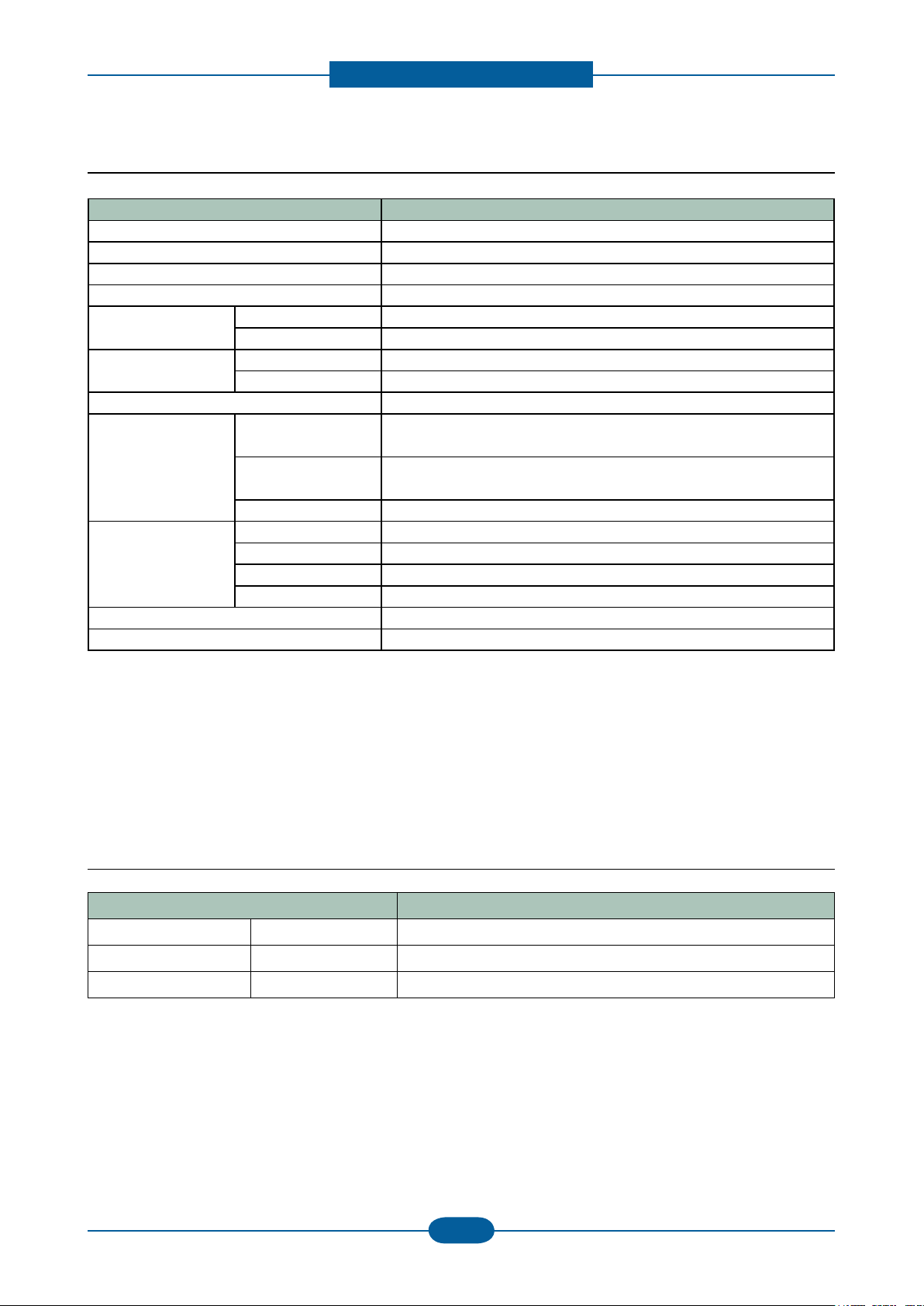
2.1.2 Specications
• Product Specications are subject to change without notice. See below for product specications.
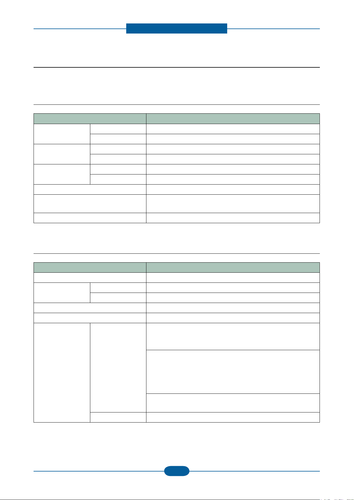
2.1.2.1 General Print Engine
Item Description
Engine Speed Simplex Up to 33 ppm in A4 (35 ppm in Letter)
Duplex Up to 17 ipm in A4 (18 ipm in Letter)
FPOT From Ready Less than 8.5 sec
From Power Save Less than 25 sec
Resolution Optical 600 x 600 dpi
Enhanced Addressible 1200 dpi
Printer Languages PCL6, PostScript3, PDF 1.4, TIFF, EPSON/IBM Pro (Israel only)
Fonts PCL:93 scalable, 1 bitmap, PS:136, OCR Font(OCR-A, OCR-B),
barcode, 2-D barcode
Downloadable Fonts Yes (PCL & PS3 S/W Font)
2.1.2.2 Controller & S/W
Item Description
Processor Chorus3 360Mhz
DRAM Std. 256 MB
Max. 512 MB
Memory Expansion 1 DDR1 SODIMM Slots(Option Memory: 256MB DDR1)
Storage(Std.) 80GB HDD
Printer driver Supporting OS [Windows]
- Windows 2000/XP(32/64bit)/2003(32/64bit)/Vista(32/64bit)/
2008(32/64bit)
[Linux]
- RedHat 8.0 ~ 9.0
- Fedora Core 1~4
- Madrake 9.2 ~ 10.1
- SuSE 8.2 ~ 9.2
[Mac]
- Mac OS X 10.3~10.5
Default Driver PCL6 (For Windows), PS (for Mac, Linux)
Page 13
Product spec and feature
Service Manual
2-3
Samsung Electronics
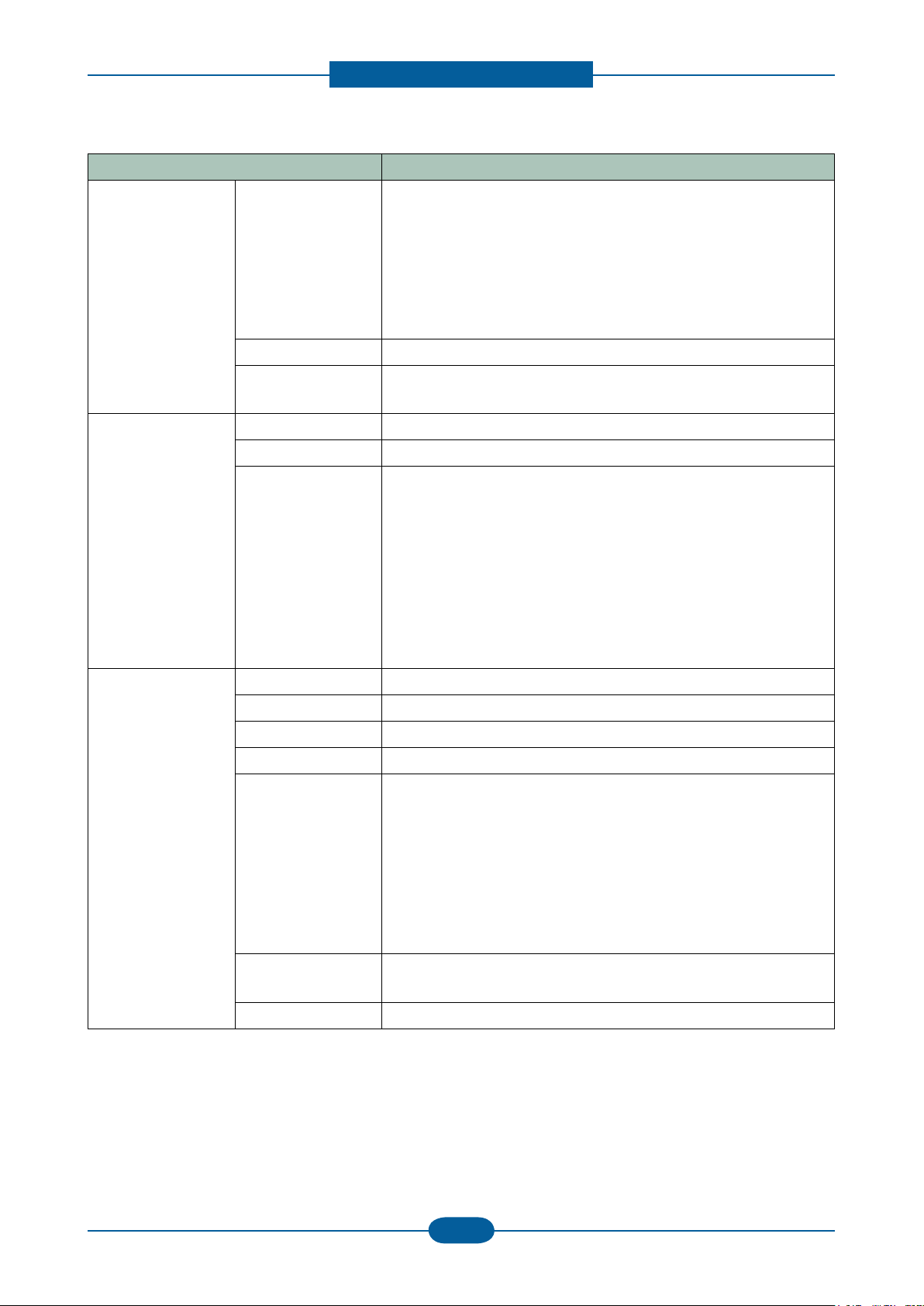
Item Description
Printer driver
(Continue..)
Driver feature [Windows]
- Watermark, Overlay, N-up printing, Poster printing
- Duplex, Quality, Color mode (Color, Gray scale)
- Support Color spec., Device color, color management
[Mac/Linux]
- N-up printing, Duplex, Quality
- Color mode (Color, Gray scale)
WHQL Windows 2000/XP(include 64bit)/2003/Vista
Language
Localization
English, French, German, Italian, Spanish, Korean, Russian,
Brazilian Portuguese
Scan driver TWAIN Yes (N/W and USB)
WIA Yes (USB Only)
Supporting OS [Windows]
- Windows 2000/XP(32/64bit)/2003/Vista(32/64bit)
[Linux]
- RedHat 8 ~ 9
- Fedora Core 1~4
- Madrake 9.2 ~ 10.1
- SuSE 8.2 ~ 9.2
[Mac]
- Mac OS 10.3~10.5
Application PC-FAX Yes
NW-FAX Yes (Supported through SmarThru Ofce)
OCR ReadIRIS
Smart Panel Yes (Install default: Windows, Linux, Mac)
Network
Management
Set IP, SWAS 4.0 & SWS
SWAS Plug-In
- Job Accounting, Storage management, Cloning, Remote Install
* Supported Web Browser:
- IE 5.5 or higher
- FireFox 1.5 or higher
- Safari 1.3 or higher
HDD File
N/A
Management S/W
SmarThru Smarthru Ofce v2.0, SmarThru WorkFlow v2.0 (Optional)
Page 14
Product spec and feature
Service Manual
2-4
Samsung Electronics
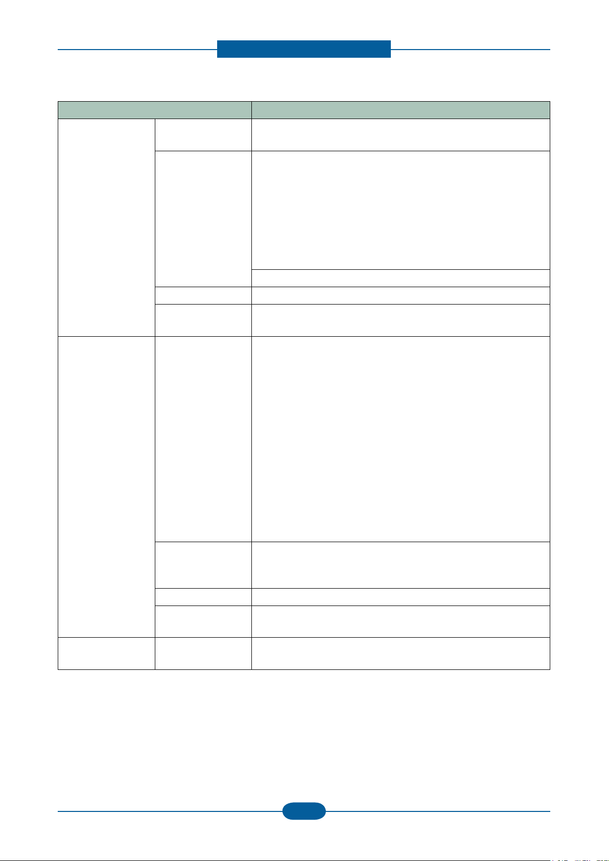
Item Description
Interface Parallel
(IEEE 1284)
USB Hi-Speed USB 2.0 Host (2 channel)
Wired LAN Ethernet 10/100/1000 Base TX
Foreign Device
Interface (FDI)
Network
Network OS [Windows]
Interface
No
* Use:
• Front
- Scan to USB
- USB direct printing
- F/W down load for system upgrade
• Rear
- Card Reader w/ Jscribe
Hi-Speed USB 2.0 Peripheral (1Channel)
Optional
- Microsoft Windows
2000/XP(32/64bits)/2003(32/64bits)/Vista(32/64bits)
[Mac]
- Mac OS 10.3~10.5
[Linux]
- RedHat 8 ~ 9
- Fedora Core 1~4
- Madrake 9.2 ~ 10.1
- SuSE 8.2 ~ 9.2
[Novell]
- Netware 5.x, 6.x(TCP/IP Only)
[Others]
- Unix(HP-UX,Solaris,SunOS, SCO)
Protocol * TCP/IP :
TCP/IPv4, HTTP, SNMPv1/v2c/V3, LDAP, SMTP, SSL/TLS,
IPSec
IP Addressing Static IP, Auto IP, BOOTP, DHCP
SNMP/MIB Access Host Resource MIB(RFC 2790), Printer MIB(RFC 3805)
Finisher MIB(RFC(3806), Samsung private MIB, SNMP Trap
User Interface LCD 800 x 480 7 WVGA Color graphic LCD with Touch-Screen, 16bit
color
Page 15
Product spec and feature
Service Manual
2-5
Samsung Electronics
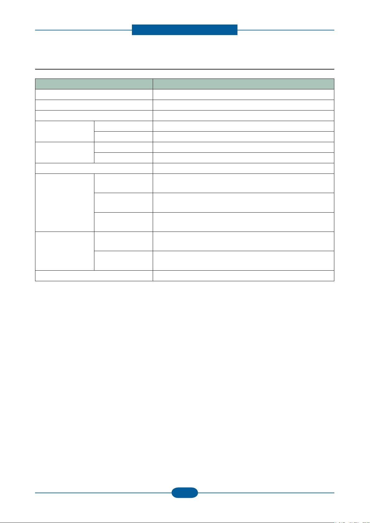
2.1.2.3 Scan
Item Description
Scan method Color CCDM
Compatibility TWAIN(USB & N/W), WIA(Only for USB)
Color Mode Mono / Gray / Color
Scan Speed Color/Mono. Gray 0.73msec/line @600*600dpi
Mono Binary 0.365msec/line @300*300dpi
Resolution Optical 600 x 600ppi
Enhanced 4,800 x 4,800ppi
Gray Scale 256 levels
Scan Size Max. Document
Max.216mm(8.5)
Width
Efective Scan
Max 208mm(8.2inch)
Width
Max. Document
Max.356mm (Legal)
Length
Scan Depth Color Internal : 36 bits
External : 24 bits
Mono - 1bit for Linearity & Halftone
- 8Bits for Gray scale
Image Compression PDF,JPEG,BMP,TIFF
Page 16
Product spec and feature
Service Manual
2-6
Samsung Electronics
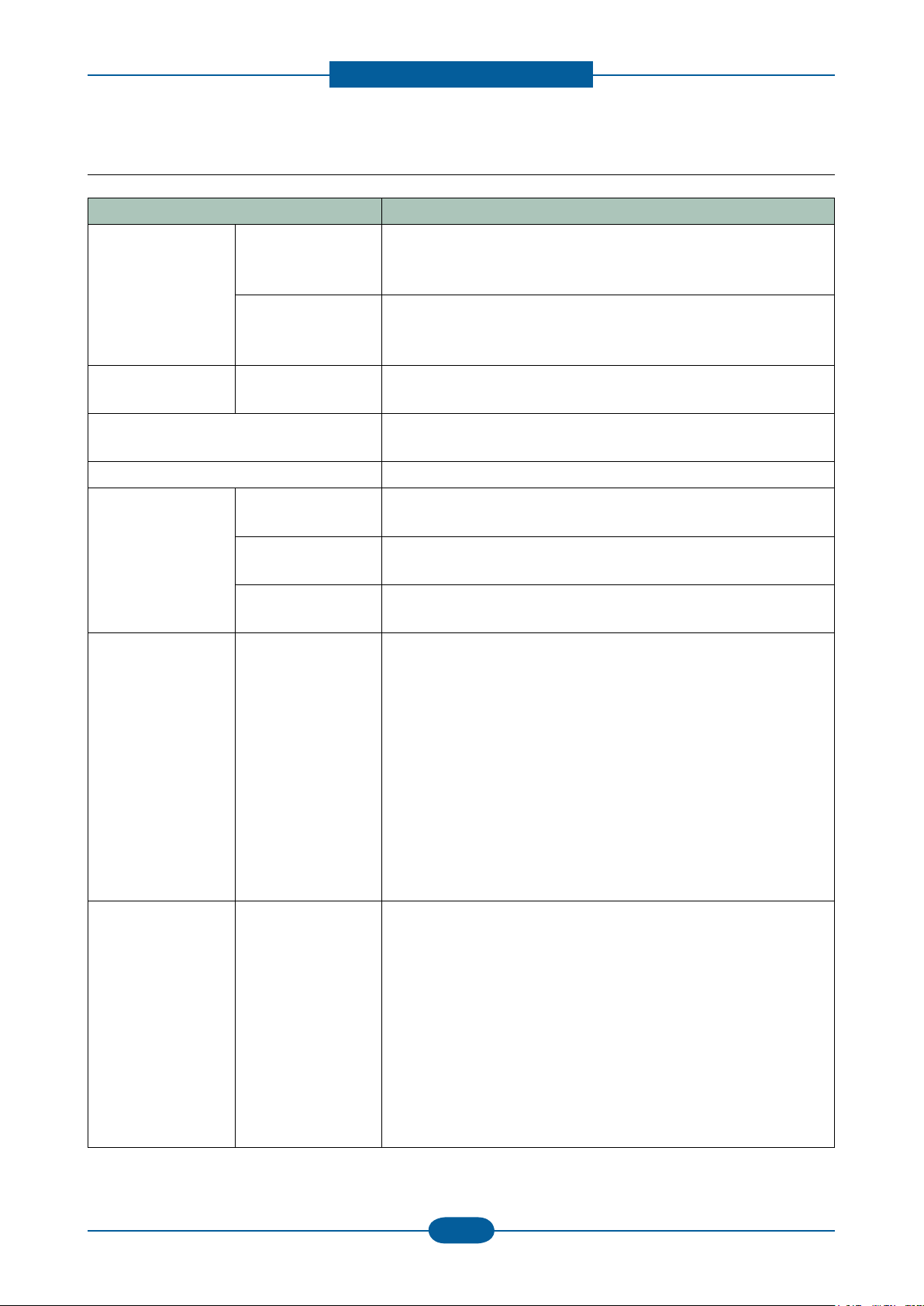
2.1.2.4 Copy
Item Description
Copy Speed
(DADF)
SDMC
(Single Document
Multiple Copy)
MDSC
(Multiple Document
Single Copy)
FCOT From Ready Platen : Less than 9.5 sec
Zoom Range 25% ~ 400% in 1% increments (Platen)
Multi Copy 1~999
Original Type Text Platen: Scan 600x600dpi , Printing 600x600dpi
Simplex: up to 33 cpm in A4 (35 cpm in Letter)
Duplex : up to 17 cpm in A4 (18 cpm in Letter)
Simplex: up to 29 cpm in A4 (30 cpm in Letter)
Duplex : up to 12 cpm in A4 (13 cpm in Letter)
DADF : Less than 11.5 sec
25% ~ 200% in 1% increments (DADF)
DADF: Scan 300x300dpi, Printing 600x600dpi
Text/Photo Platen: Scan 600x600dpi, Printing 600x600dpi
DADF: Scan 300x300dpi, Printing 600x600dpi
Photo Platen: Scan 600x600dpi, Printing 1200x1200dpi
DADF: Scan 300x300dpi, Printing 600x600dpi
Reduce & Enlarge * Zoom Range : 25% to 400% in Platen, 25% to 200% in ADF
* Preset
[Original(100%)]
[Auto Fit]
[A4 → A5(71%)]
[LGL→LTR(78%)]
[LGL→A4(83%)]
[A4→LTR(94%)]
[EXE→LTR(104%)]
[A5 → A4(141%)]
25%, 50%,150%, 200%, 400%
[Custom:25-400%)]
Duplex Copy Using Platen
- 1 → 1Sided
- 1 → 2Sided
Using DADF
- 1 → 1Sided
- 1 → 2Sided Short,
- 1 → 2Sided Long,
- 2 → 1Sided
- 2 → 1Sided, Rotate Side2
- 2 → 2Sided Short
- 2 → 2Sided Long
Page 17
Product spec and feature
Service Manual
2-7
Samsung Electronics
2.1.2.5 Fax
Item Description
Compatibility ITU-T G3
Communication System PSTN/PABX
Modem Speed 33.6Kbps
TX Speed 3sec (Mono/Standard/ECM-MMR, ITU-T G3 No.1 Chart)
Compression MH/MR/MMR/JBIG/JPEG
Color Fax Yes (TX only)
ECM Yes
Resolution
(Mono)
Std 203*98dpi
Fine 203*196dpi
S.Fine 300*300dpi
Resolution
(Color)
Std 200*200dpi (TX Only)
Fine 200*200dpi (TX Only)
S.Fine 200*200dpi (TX Only)
Scan speed Platen 0.365msec/line at 300*300dpi
DADF 0.365msec/line at 300*300dpi
Telephone
Features
Speed Dial 200 Locations
One touch dial NONE
Chain Dial NONE
Manual Dial Yes
Last Number
Yes
Redial
Automatic Redial
Yes
Transmission
Pause Yes
Flash No
Handset & Cradle NONE
Ringer Volume OFF. LOW, MEDIUM, HIGH
Tone/Pulse Select Selectable in Tech Mode
VoIP Support Yes. ( The communication in VoIP network is supported, but
the fax quality may be fallen. Beacause the purpose of VoIP
network is not fax but Internet network for voice. )
Page 18
Product spec and feature
Service Manual
2-8
Samsung Electronics
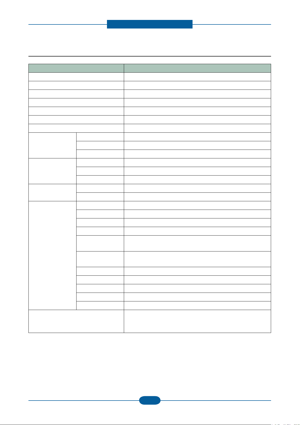
2.1.2.6 Paper Handling
Item Description
Bypass Tray Capacity Plain paper : 50 sheets
Transparency : 5 sheets
Envelopes : 5 sheets
Media sizes 76.2x127 mm(3x5) ~ 215.9x355.6mm (8.5x14.0)
Banner Size Printing : 216mm x 900mm
Media type Printer Default, Plain Paper, Thick Paper, Thin Paper, Bond
Paper, Color Paper, CardStock, Labels, Transparency,
Envelope, Preprinted, Cotton, Recycled Paper, Archive
Media weight 16~43lb (60 to 163g/m²)
Standard
Cassette
Tray
Capacity 500 sheets @ 20lb (80g/m²)
Media sizes Letter, Legal, Ocio, Folio, A4, JIS B5, ISO B5, Executive, A5
Media types Plain Paper, Thin Paper, Pre-Printed, Recycled, Thick, Archive
Media weight Plain Paper : 75~90 g/m²
Thin Paper : 60~70 g/m²
Thick Paper : 90~105 g/m²
Pre-Printed : 75~90 g/m²
Recycled : 60~90 g/m²
Duplex : 75~90 g/m²
Optional
Cassette
Tray(SCF)
Optional
Cassette
Tray(SCF)
(Continue..)
Capacity 500 sheets @ 20lb (80g/m²), drawer type
Media sizes Letter, Legal, Ocio, Folio, A4, JIS B5, ISO B5, Executive, A5
Media types Plain Paper, Thin Paper, Pre-Printed, Recycled, Thick, Archive
Media weight Plain Paper : 75~90 g/m²
Thin Paper : 60~70 g/m²
Thick Paper : 90~105 g/m²
Pre-Printed : 75~90 g/m²
Recycled : 60~90 g/m²
Duplex : 75~90 g/m²
Output Stacking 250 sheets @ 20lb (80g/m²)
DADF Capacity 50 sheets ( 20lb, 80g/m²)
2-sided Document
Yes (Reversing)
Scanning
Document Size Width: 145 ~ 216mm (5.7~8.5)
Length : 145 ~ 356mm (5.7 ~ 14.0) for Single page scan
145 ~ 400mm (5.7 ~ 15.7) for Multi pages scan
Bank Check Scan : 69.6mm x 152.4mm
Document Weight 12.5~28lb
Page 19
Product spec and feature
Service Manual
2-9
Samsung Electronics
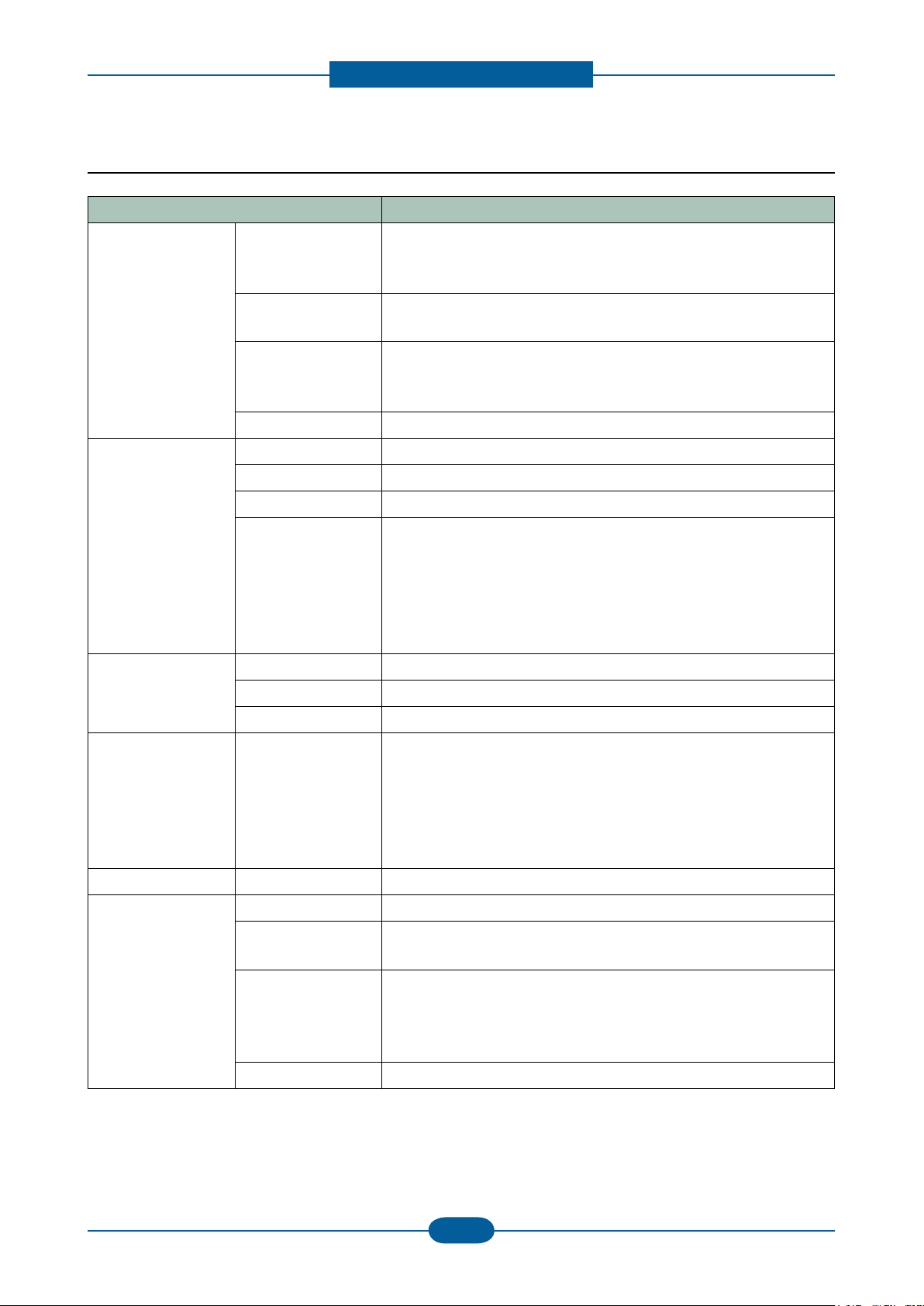
2.1.2.7 Consumables (CRU)
Item Description
Toner Cartridge MLT-D206S Average Continuous Black Cartridge Yield: 4,000* standard
pages
* Declared yield value in accordance with ISO/IEC 19752
MLT-D206L Average Continuous Black Cartridge Yield: 10,000* standard
pages
* Declared yield value in accordance with ISO/IEC 19752
2.1.2.8 Consumables (FRU)
Item Item Description
DADF Rubber Pad JC97-03069A 50,000 feeds
DADF Pick-up Assembly JC97-03070A 100,000 feeds
Pick up roller JC97-02441C 150,000 feeds
Transfer Roller JC66-01181A 100,000 images
Fuser Unit JC96-05064A(220V)
JC96-05063A(110V)
100,000 images
Page 20
Product spec and feature
Service Manual
2-10
Samsung Electronics
2.1.2.9 Service & Environment
Item
AMPV
Max Monthly Duty
MPBF ( Mean Page Between Failure)
MTTR (mean time to repari)
Temperature
Humidity
Input Voltage
Noise
Power Consumption
Dimensions (WxDxH)
Weight (with consumables)
Operating 10℃ ~ 32℃
Storage 20℃ ~ 40℃
Operating 20~80% RH
Storage 10~90% RH
Printing
Simplex / Duplex
Copying
Simplex / Duplex
Standby 39 dB
Ready Less than 100W
AVG. Less than 750W
Power save Less than 25W
Power off 0W
Description
2500 pages/month (A4 size, IDC 5% coverage)
75,000 pages/month (A4 size, IDC 5% coverage)
50,000 pages
30 minutes
AC 110-127V or AC 220-240V
52 dB
54 dB
500x465x547 mm
23.1Kg
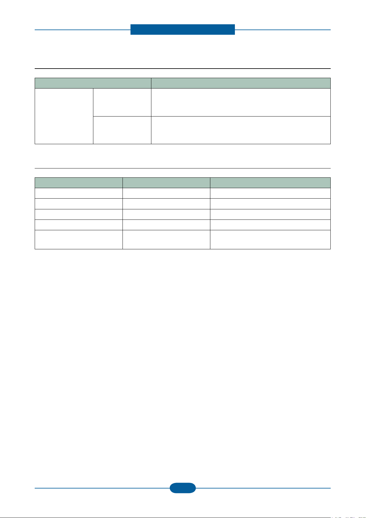
Item Description
Optional Tray (SCF) SCX-S5835A 500 sheets feeder
Memory CLP-MEM202 256 MB
Jscribe SCX-KIT10J JScribe Related S/W Enabler
Page 21
Product spec and feature
Service Manual
2-11
Samsung Electronics
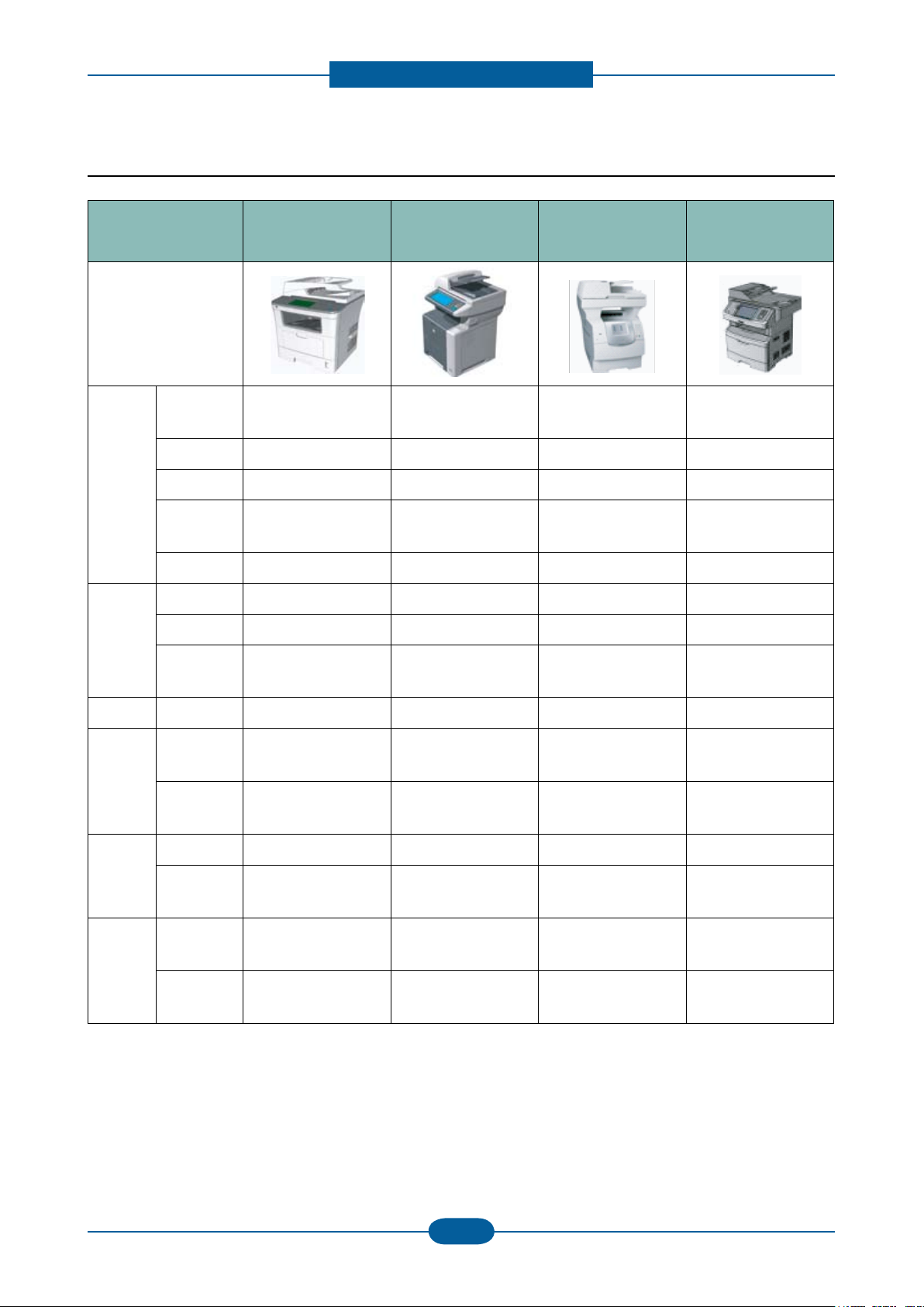
2.1.3 Model Comparison
Printer
Copy
SAMSUNG
SCX-5835NX
SCX-5935NX
Image
Speed
(A4/Ltr.)
Copy size A4 A4 Legal Legal
Resolution 1,200 x 1,200 dpi 1,200 x 1,200 dpi 1,200 x 1,200 dpi 1,200 x 1,200 dpi
Emulation
Duplex Print Standard Standard Option Standard
Speed 35cpm 35cpm 35cpm 35cpm (Estimated)
Resolution 600dpi 600 dpi 600 dpi 600 dpi (Estimated)
Zoom 25 – 400% 25 – 400% 25 – 400%
33ppm/35ppm 33ppm/35ppm 43ppm/45ppm 38ppm/40ppm
PCL5e, PCL6, PS,
PDF1.5
HP
LJ M3035
PCL5, PCL6, PS,
PDF1.5
Lexmark
X642e
PCL5, PCL6, PS,
PDF1.5
Lexmark
New 4dte
PCL5, PCL6, PS,
PDF1.5
25 – 400%
(Estimated)
Scan Resolution 600dpi 600dpi 600dpi 600dpi (Estimated)
Fax
Paper
Handling
General
Modem
Speed
Memory HDD Backup
DADF 50sh. 50 sh 50sh. 50sh.
Input
Tray(Std.)
Memory
Std.(Max)
Toner 4K, 10K
33.6 Kbps LJ-M3035xs Only 33.6 Kbps 33.6 Kbps
HDD Backup
(LJ-M3035xs Only)
500 sh. Tray
50 sh. MP
256MB(512MB) 128MB(640MB) 256MB(?)
500 sh. Tray
100 sh. MP
Q7551x
(13,000 sh.)
- HDD Backup
500 sh. Tray
100 sh. MP
10K, 21K 9K, 15K
2 x 250 sh. Tray
50 sh. MP
Page 22
Product spec and feature
Service Manual
2-12
Samsung Electronics
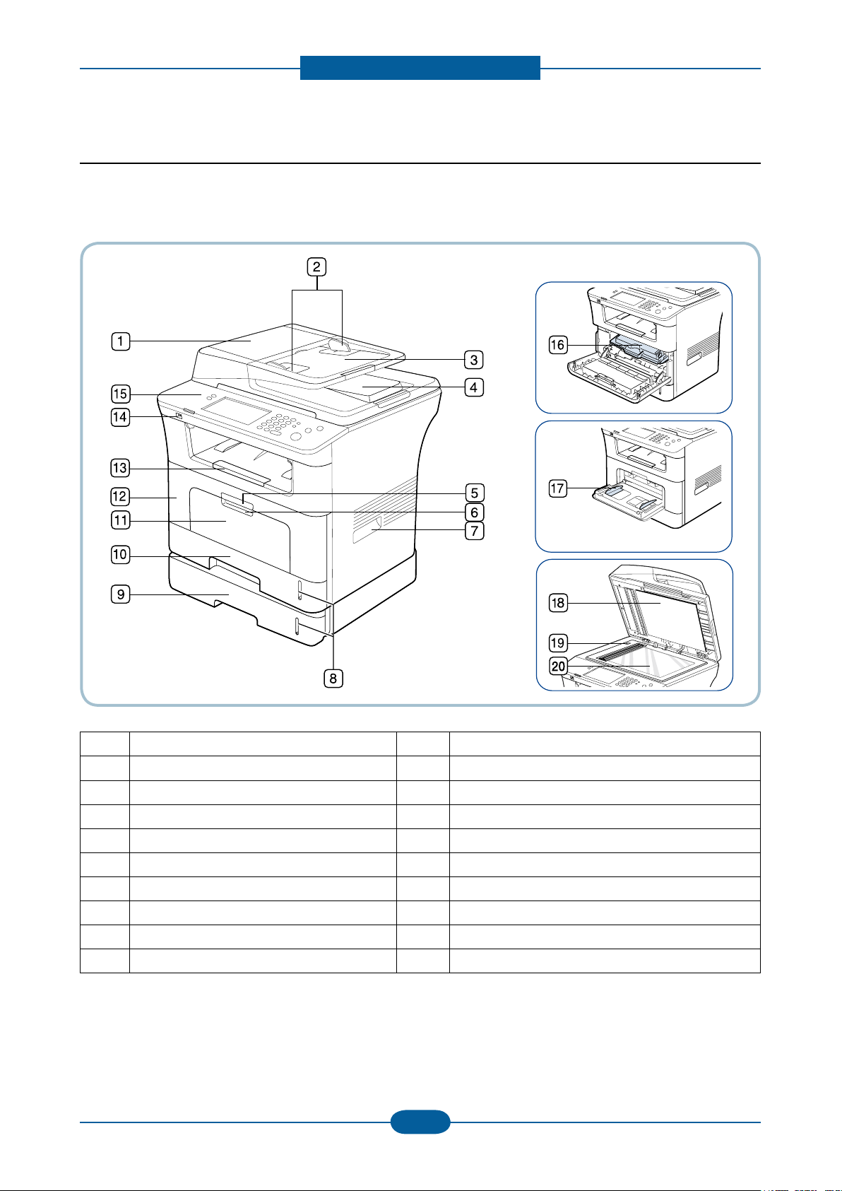
2.2 System Overview
■ Front View
1 Document feeder cover 11 Multi-purpose tray
2 Document feeder width guides 12 Front cover
3 Document feeder input tray 13 Document output tray
4 Document feeder output tray 14 USB memory port
5 Front cover handle 15 Control panel
6 Multi-purpose tray handle 16 Toner cartridge
7 Handle 17 Multi-purpose tray paper width guides
8 Paper level indicator 18 Scanner lid
9 Optional tray 2
10 Tray 1 20 Scanner glass
[a] Optional device.
[a]
19 Scanner lock switch
Page 23
Product spec and feature
Service Manual
2-13
Samsung Electronics
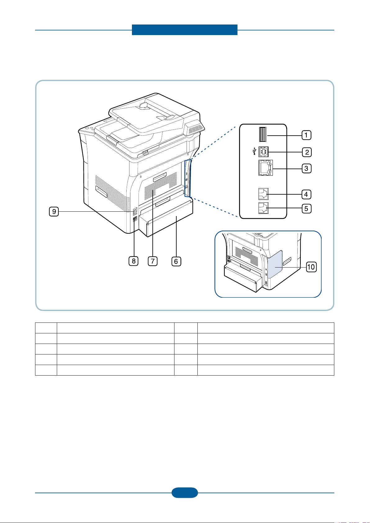
■ Rear View
1 USB host port 6 Duplex unit
2 USB port 7 Rear cover
3 Network port 8 Power receptacle
4 Telephone line socket 9 Power-switch
5 Extension telephone socket (EXT) 10 Control board cover
Page 24
Product spec and feature
Service Manual
2-14
Samsung Electronics
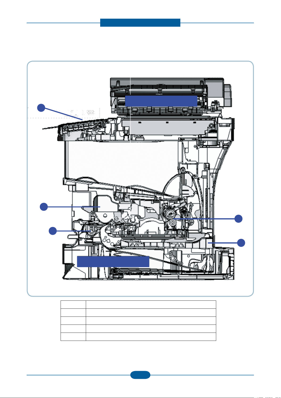
■ System Layout
520 sh. Cassette
Scanner / DADF
5
4
3
2
1
500 sh. Cassette
Scanner / DADF
5
4
3
2
1
1 OP Panel / 7 “ LCD Touch Screen
2 Toner Cartridge
3 MP Roller
4 Fuser Unit
5 Duplex Unit
Page 25
Product spec and feature
Service Manual
2-15
Samsung Electronics
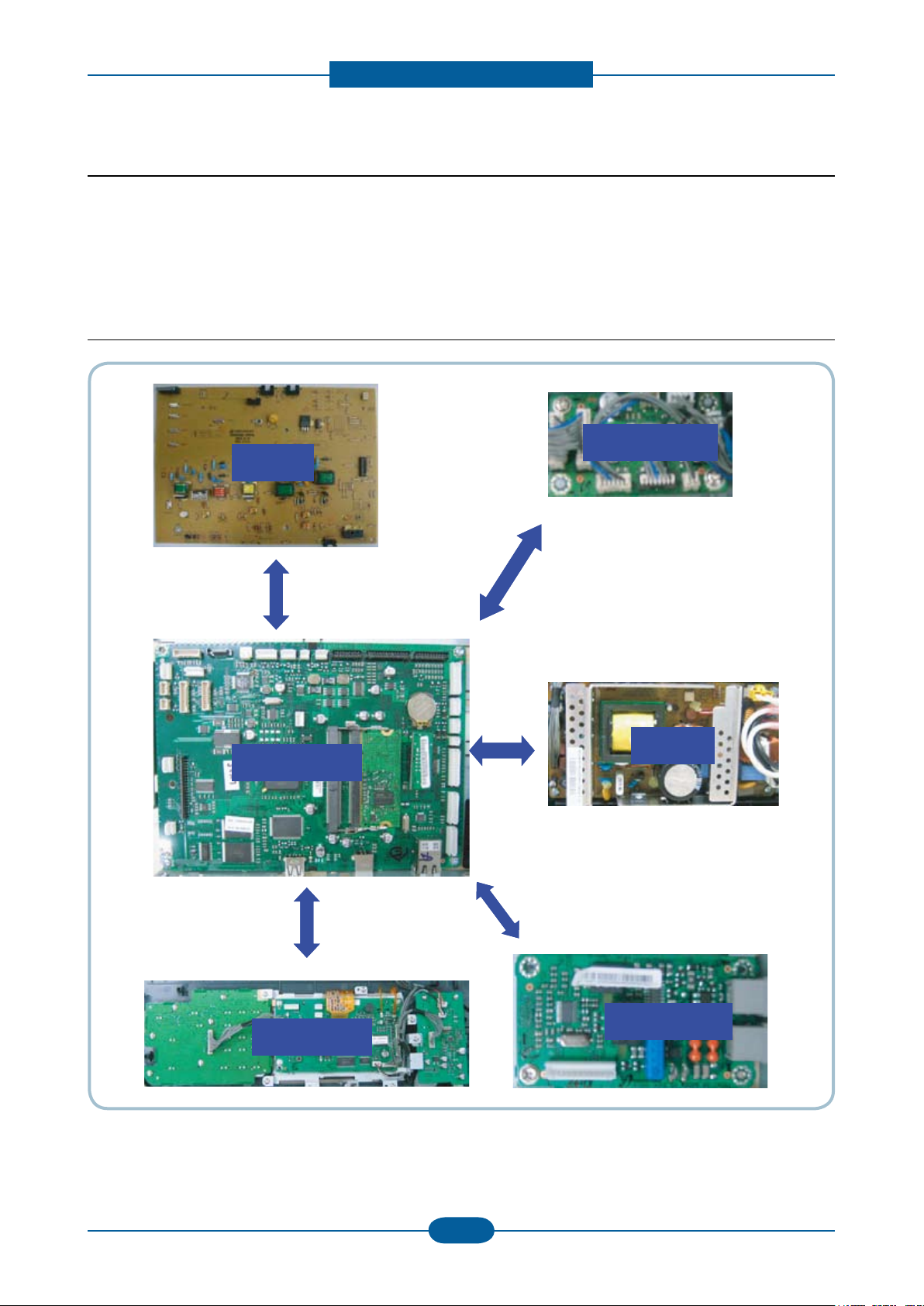
HVPS
MAIN PBA
OPE PBA
DADF PBA
SMPS
Fax Board
HVPS
MAIN PBAMAIN PBA
OPE PBA
DADF PBA
SMPSSMPS
Fax Board
2.2.1 System Conguration
SCX-5835NX_5935NX Series consist of Main Control Part, Operation Panel Part, Scanner Part, Line
Interface Part ,Power Part and Optional DIMM(Dual-In-Memory Module) for Scan-To-Email.
Main Controller is commonly applied in all products, SCX-5835NX_5935NX Series, and in case of necessary
a part of components or Module is selectively adopted in accordance with required feature of each model.
2.2.2 Hardware Conguration
Page 26
Product spec and feature
Service Manual
2-16
Samsung Electronics
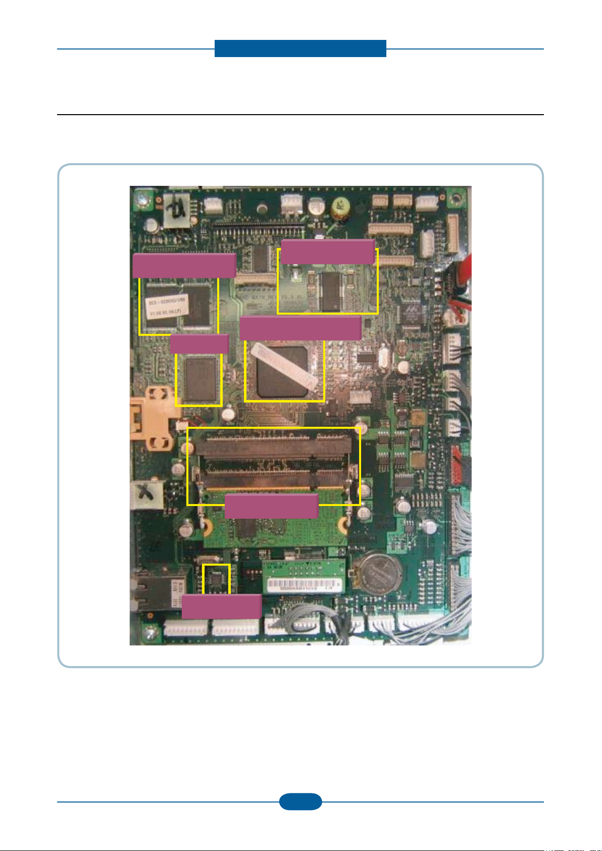
4-1. Main Board
Scan MOTIC
CHORUS3(ASIC)
Flash Memory
USB IC
DDR2 DIMM
Network IC
4-1. Main Board
Scan MOTIC
CHORUS3(ASIC)
Flash Memory
USB IC
DDR2 DIMM
Network IC
2.2.2.1 Main Controller
The Main Control Part comprises 1 CPU and 1 B’D by adopting the dedicated Controller for Fax & LBP. The
Scanner Part comprises DADF& CCD and connected with Main board through Harness.
Page 27

Product spec and feature
Service Manual
2-17
Samsung Electronics
CPU (CHORUS3)
It uses the ARM 926EJS, 32Bit RISC Processor, which is dedicated Controller for Printer & Fax function and
drives the each internal Operation Block by system program of Flash Memory and thereby controlling the
whole System.
- Main Function Block : Completely Integrated System for Embedded Applications,
▶ 32 Bit RISC Architecture, Efcient and Powerful ARM 926EJS Core.
▶ LSU Interface Module for Interfacing PVC or HPVC with LSU
▶ Dual Memory Bus Architecture
- Operation Frequency : AHB Bus: 133MHz, Internal System Bus: 120MHz
- Operation Power : 3.3V / 1.0V(core)
Flash Memory
It stores system program, Fonts data(PCL, PS/3), and can download the system program through PC
Interface or Network.
- Capacity: 32M Byte
- Access Time : 80 nsec
System Memory (DDR2)
It is used as Swatch Buffer for Printing, Scan Buffer for Scanning and System Working Memory Area.
- System memory: 256MB Capacity
- Max Frequency: 120 MHz
System Data Memory (EEPROM + Flash Memory)
This memory, which is for storing the operation variable & the setting parameter of Elbert2, keeps the
information.
Optional Memory (DIMM)
SCX-5835NX_5935NX Series provide one (1) Extension Slot for extending Memory. The RAM Extension
Slot can be used for:
General Memory Extension
256 MB Optional Memory is available.
Page 28
Product spec and feature
Service Manual
2-18
Samsung Electronics
Fuse 5V
Fuse 5V
Fuse 24V
Fuse 24V
Fuse 5V
Fuse 5V
Fuse 5V
Fuse 5V
Fuse 24V
Fuse 24V
Fuse 5V
Fuse 5V
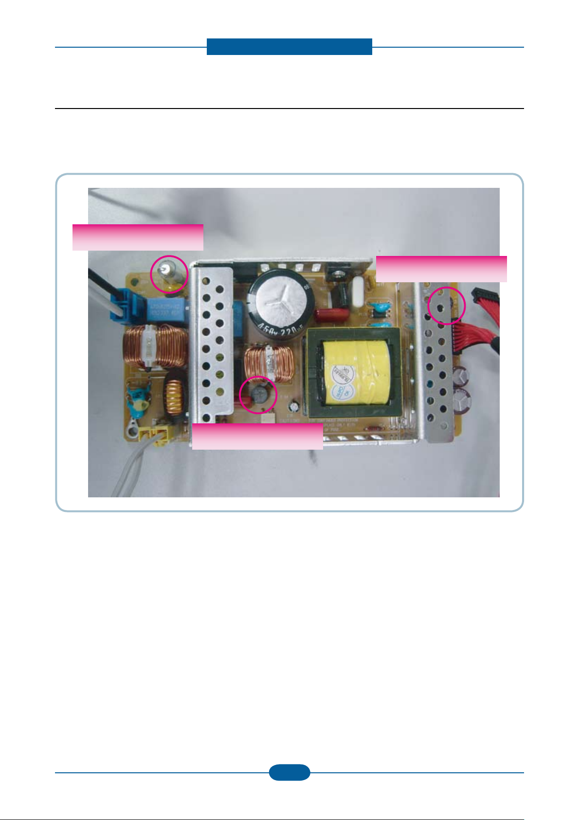
2.2.2.2 SMPS board
SMPS( Switching Mode Power Supply ) Board supplies electric power to a Main Board and other boards
through a Main Controller by +5V,+24V from 110V/220V power input. It has safety protection modes for over
current and load.
Page 29
Product spec and feature
Service Manual
2-19
Samsung Electronics
DC Output Connector( CON3 )
Description PIN NO PIN ASSIGN PIN NO Description
Fuser ON
(Active High)
Fuser_On 1 2 24VS
Power
(Photo Triac Bias)
Power +24V 3 4 GND +24V Ground
Power +24V 5 6 GND +24V Ground
Power +24V 7 8 GND +24V Ground
Power +24V 9 10 GND +24V Ground
Power +5V 11 12 GND +5V Ground
Power +5V 13 14 GND +5V Ground
Relay On Relay_On 15 16 OFF/SINK +24V On/OFF
AC Input Connector( CON1 )
SMPS → Heater Controller( CON2 )
PIN ASSIGN PIN NO Description
1 AC_L
AC Input
2 AC_N
PIN ASSIGN PIN NO Description
1 AC_L
AC Output
for Heater
2 AC_N
Page 30
Product spec and feature
Service Manual
2-20
Samsung Electronics
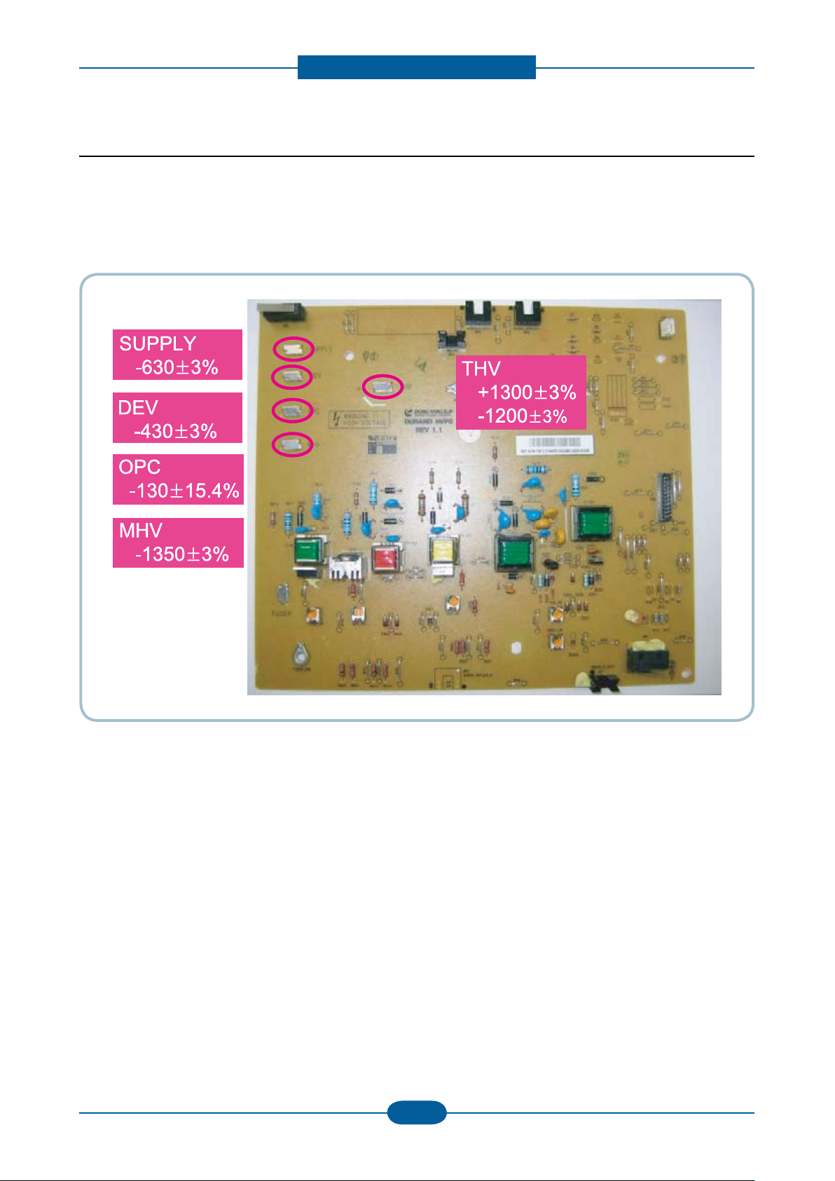
2.2.2.3 HVPS board
HVPS(High Voltage Power Supply)
HVPS Part outputs the generated high voltage for THV/MHV/BIAS/DETACH/FUSER BIAS by inputting 24V,
and the output high voltage is provided into OPC Cartridge and Transfer Roller.
Page 31

Product spec and feature
Service Manual
2-21
Samsung Electronics
2.2.2.4 FAX Board
Specications
• LINE CONNECTION: PSTN or PABX (RJ-11)
• Compatibility: ITU-T G3, Super G3
• Communication System: PSTN/PABX
• Modem Speed: 33.6Kbps
• TX Speed: 3 sec
* Standard Resolution, MMR, 33,6Kbps
* Phase “C” by ITU-T No.1 Chart in Memory transmission with ECM
• Scan Speed
Platen -> 2 sec / A4
ADF -> 5.5 sec / A4
* Scan time: 2 sec/A4 @ 203x98dpi * Scan setup time : 3.5 sec
• Receive Mode: Fax, TEL, ANS/FAX
• Compression: MH/MR/MMR/JBIG/JPEG
• ECM: Yes
• Resolution Std: 203*98dpi
Fine: 203*196dpi
S.Fine: 300*300dpi
• Contrast: Adsustable 5 levels
• Fax Memory: 32MB (in HDD)
Page 32

Product spec and feature
Service Manual
2-22
Samsung Electronics
2.2.3 Mechanic Conguration
2.2.3.1 Feeding Section
1) Cassette
It stores and automatically feeds print paper.
Pick-up Roller picks up paper, controls drive, feeds paper, removes static electricity, and so on.
> Spec.
* Feeding Method : Cassette Type
* Feeding Standard : Center Loading
* Feeding Capacity : Cassette 500 Sheets
(80g/ , 20lb Paper Standard)
* Paper Detecting Sensor : Photo Sensor
(Empty, Registration, Exit)
* Paper Size Sensor : None
2) MPF
> Spec.
* Capacity : Plain paper : 50 sheets
Transparency : 5 sheets
Envelopes : 5 sheets
* Media sizes : 76.2x127mm(3”x5”)
~215.9x355.6mm(8.5”x14.0”)
* Media weight : 16~43lb(60 to 163 g/m²)
Page 33

Product spec and feature
Service Manual
2-23
Samsung Electronics
2.2.3.2 Drive Unit
Drive Unit is used for image process.
Main Drive Unit is for Paper path(Pick up, Feeding, Registration).
Fuser Drive unit is for Fuser Driving, Exit roller
Duplex Drive unit is for Duplex feeding.
[ Main Drive Unit ]
[ Duplex Drive Unit ]
[ Fuser ]
Page 34

Product spec and feature
Service Manual
2-24
Samsung Electronics
OPC Drum
Photo Diode
LD Driver circit
Protector panel
LD(Laser Diode)
Polygon Mirror
Polygon Motor
Motor Driver
2.2.3.3 LSU ( Laser scanning unit )
LSU consists of LD(Laser Diode) and polygon motor control. For realizing Color Image, it is controled by 4
LD. When the controller generate the printing signal, LD will turn on and Polygon motor starts.If the receiving
part in LSU detect the beam , Hsync is generated. When the rotation of polygon motor is steady, it is time of
LSU ready status for printing. If either of two condition is not satised, LSU error is expected.
Page 35

Product spec and feature
Service Manual
2-25
Samsung Electronics
2.2.3.4 Fuser Unit
This unit consists of IH-HEAT ROLLER, Thermostats and a Thermistor. It melts and fuses the toner,
transferred by the transfer roller onto the paper, by applying pressure and high temperature to complete
printing job.
- Fusing type : Thermal xing with a couple of one heat roller and two pressure rollers
- Hear roller : ø28.3, Anodized, singel halogen lamp, thick brown color coating
- Pressure roller 1 : ø16.0 : PFA tube, Electrically conductive
- Pressure roller 2 : ø20.0 : LSR+PFA, Electrically conductive
- Single thermistor and a pair of thermostat
- A ball bearing at each end of heat roller (total amount; two)
- Jam removal lever / Fuser door open for jam removal
- Life span : 80,000 pages
① Thermostat
When a heat lamp is overheated, a Thermostat cuts off the main power to prevent over-heating.
- Non-Cotact type Thermostat
② Heat roller
The heat roller transfers the heat from the lamp to apply a heat on the paper. The surface of a heat roller
is coated with Teon, so toner does not stick to the surface.
③ Pressure roller
A pressure roller mounted under a heat roller is made of a silicon resin, and the surface also is coated with
Teon. When a paper passes between a heat roller and a pressure roller, toner adheres to the surface of
a paper permanently.
Trouble Temperature Control concept
Open Heat Error 85˚C below for 20 sec after power on
Over Heat Error
(Fuser High Error)
Low Heat Error
(Fuser Low Error)
- 220˚C over for 20sec
- 230˚C over for 3sec
10˚C below than target Temp. for 10 sec. At Warm up
20˚C below than target Temp. for 10 sec. At Printing
20˚C below than target Temp. for 10 sce. At stand-by
16˚C below than target Temp. for 10 sce. At pick up
Page 36

Product spec and feature
2.2.3.5 Scanner Section
1) Optical System: Lens Reduction type All-In-One (Scanning Lamp + Lens + CCD Image sensor).
2) Light Source: White LED(Light Emitting Diode)
3) Scanning method:
- Platen: Optical Moving
- DADF: Document Moving
* Scanning Area
Maximum Document Width: 216mm
Effective Scanning Width: 208mm
* Source Document Specication (DADF)
1) DADF capacity : 50 sheets of 20lbs /80gsm paper
2) Specication
Item Specication Item Specication
Length 145~356mm Weight 12.5lb ~ 28lb
Width 142~216mm Thickness 0.075mm ~ 0.13mm
Curl Below 5mm - This machine must be able to
feed the documents in Normal
Environment / Standard Paper
(20lb/80gsm)
Service Manual
2-26
Samsung Electronics
Page 37

Disassembly and Reassembly
3. Disassembly and Reassembly
3.1 General Precautions on Disassembly
When you disassemble and reassemble
components, you must use extreme caution. The
close proximity of cables to moving parts makes
proper routing a must.
If components are removed, any cables disturbed
by the procedure must be restored as close as
possible to their original positions. Before removing
any component from the machine, note the cable
routing that will be affected.
Whenever servicing the machine, you
must perform as follows:
1. Check to verify that documents are not stored in
memory.
2. Be sure to remove the toner cartridge before you
disassemble parts.
3. Unplug the power cord.
4. Use a at and clean surface.
5. Replace only with authorized components.
Releasing Plastic Latches
Many of the parts are held in place with plastic
latches. The latches break easily; release them
carefully.
To remove such parts, press the hook end of the
latch away from the part to which it is latched.
6. Do not force plastic-material components.
7. Make sure all components are in their proper
position.
Service Manual
3-1
Samsung Electronics
Page 38

Disassembly and Reassembly
Service Manual
3-2
Samsung Electronics
3.2 Maintenance Parts
Sec_Code Description Life Image
JC97-02441C MEA-ROLLER PICK UP 150K
JC66-01181A ROLLER-TRANSFER 100K
JC96-05064A(220V) ELA UNIT-FUSER 100K
JC97-03070A MEA UNIT-PICK UP DADF 100K
JC97-03069A MEA UNIT-DADF RUBBER 50K
JC97-03249A MEA UNIT-HOLDER PAD
(Cassette friction pad)
100K
Page 39

Disassembly and Reassembly
Service Manual
3-3
Samsung Electronics
Spring
Hook
Spring
Hook
Spring
Hook
Spring
Hook
3.3 General Disassembly
3.3.1 Fuser Unit
1. Open the Rear Cover. 2. Remove the Fuser unit after remove the
4 screws.
3.3.2 DADF Pick up unit and rubber pad
1. Open the DADF Cover. Remove the DADF
rubber pad by removing both side hook.
2. Remove the DADF pick up unit by removing the
spring.
Page 40

Disassembly and Reassembly
Service Manual
3-4
Samsung Electronics
TrasferrollerTrasferroller
3.3.3 Pick up roller
1. Remove the Cassette. 2. Pull the Pick up roller to the direction of arrow
from the bottom of SET.
3.3.4 Transfer roller
1. Open the front cover and remove the toner cartrdige. To remove the Tranfer roller, Push the lever to the
direction of arrow.
Page 41

Disassembly and Reassembly
Service Manual
3-5
Samsung Electronics
3.3.5 Cover
1. Remove the Cassette.
2. Remove the Duplex Unit from the rear.
3. Open the DADF back. And Lift it up after remove
the connector.
4. Remove the 4 screws from the rear.
Page 42

Disassembly and Reassembly
Service Manual
3-6
Samsung Electronics
5. Open the Front cover. And remove the 4 screws.
6. Remove the Left Side Cover.
7. Remove the Right Side Cover.
Page 43

Disassembly and Reassembly
Service Manual
3-7
Samsung Electronics
3.3.6 DADF Board
1. Open the DADF back. And Lift it up after remove
the connector.
2. Remove the 5 screws from the bottom of DADF.
4. Remove the 3 screws from the bottom of DADF.
And remove the COVER-DADF-FRONT/REAR.
5. Disassemble the Stacker.
3. Remove the Sponge.
6. Remove all harness and 2 screws.
Page 44

Disassembly and Reassembly
Service Manual
3-8
Samsung Electronics
3.3.7 Scan Assy
1. Remove the COVER-DECO UPPER.
2. Remove the 1 screw.
3. Turn up the OPE unit. And remove the 8 screws.
4. Remove the 2 screws from the rear.
Page 45

Disassembly and Reassembly
Service Manual
3-9
Samsung Electronics
5. Remove the 1 screw.
6. Remove all harness connecting the Scan Assy.
8. Remove the Scan Upper from the Scan Lower.
9. Remove the at cable.
7. Lift the Scan Assy up.
10. Remove the CCDM module after remove the
belt unit.
Page 46

Disassembly and Reassembly
Service Manual
3-10
Samsung Electronics
3.3.8 Middle Cover
1. Remove the 2 screws.
2. Remove all harness.
3. Remove the 5 screws and all harness.
4. Remove the 1 screw.
Page 47

Disassembly and Reassembly
Service Manual
3-11
Samsung Electronics
3.3.9 HDD/ Main PBA/ Fax board
1. Remove the 4 screws and harness. Remove the
HDD Assy.
2. Remove all harness and 5 screws.
3. Remove the fax board cover after remove the
2 screws.
4. Remove the 1 screw.
Page 48

Disassembly and Reassembly
Service Manual
3-12
Samsung Electronics
3.3.10 SMPS board
1. Remove the Cover-SMPS. 2. Remove the SMPS Shield after remove the
2 screws.
3.3.11 Main Drive unit
1. Remove the Drive unit after remove the
6 screws.
Page 49

Disassembly and Reassembly
Service Manual
3-13
Samsung Electronics
3.3.12 HVPS board
LSU-UnitLSU-Unit
1. Separate the HVPS Shield after remove the
8 screws.
3.3.13 LSU Unit
Caution
When disassembling and assembling the HVPS
Shield, be careful the harness of the Cassette
Sensor.
1. Remove the LSU unit after the 2 harness and
4 screws.
Page 50

3.3.14 USB port
Disassembly and Reassembly
1. Remove the COVER-DECO UPPER
2. Remove the 1 SCREW.
3. Turn up the OPE unit
4. Remove the 5 screw, 3 harness.
Service Manual
3-14
Samsung Electronics
Page 51

Alignment & Troubleshooting
Scanner Part
Engine Part
Roller-Heat
Roller-Exit
Roller-Transfer
Roller-Pickup
Roller-Feed
Roller-MP
Roller-Pressure
Roller-REGI
OPC
Duplex
Duplex
Roller-REGI
OPC
FEED
SENSOR
SCAN
SENSOR
PAPER EMPTY
SENSOR
4. Alignment & Troubleshooting
This chapter describes some of the main service procedures including;
- Clearing paper jams
- Using the Diagnostic mode
- How to rmware upgrade
- Troubleshooting. etc.
4.1 Alignment and Adjustments
4.1.1 Paper path
Service Manual
4-1
Samsung Electronics
Page 52

Alignment & Troubleshooting
Service Manual
4-2
Samsung Electronics
FEED SENSOR
SCAN SENSOR
EXIT SENSOR
DUPLEX SENSOR
(1)
(2)
(3)
(4)
(5)
(1)JAM-0 : Paper empty sensor ~ Feed sensor
(2)JAM-1 : Feed sensor ~ Exit sensor
(3)JAM-2 : Exit sensor ~
(4)Duplex Jam-1 : ~ Duplex sensor
(5)Duplex Jam-0 : Duplex sensor ~ Feed sensor
PAPER EMPTY
SENSOR
FEED SENSOR
SCAN SENSOR
EXIT SENSOR
DUPLEX SENSOR
(1)
(2)
(3)
(4)
(5)
JAM-
PAPER EMPTY
SENSOR
4.1.2 Clearing Paper Jams
Occasionally, paper can be jammed during a print job. Some of the causes include:
• The tray is loaded improperly or overlled.
• The tray has been pulled out during a print job.
• The front cover has been opened during a print job.
• Paper was used that does not meet paper specications.
• Paper that is outside of the supported size range was used.
If a paper jam occurs, LCD window will show it’s speeds. Find and remove the jammed paper. If you don’t
see the paper, open the covers.
Do not use a pinset or a sharp metal tool when removing a jam.
The covering of a metal part can be removed which can cause an electric leakage.
■ Description of ENGINE JAM type (Layout)
Page 53

Alignment & Troubleshooting
Service Manual
4-3
Samsung Electronics
■ Description of ENGINE JAM type (Simplex)
Type Case Jam Removal Jam Layout
Leading edge of media does
Jam 0
not arrive at registration within a
certain time after pick-up(If fails
at a time,it tries pick-up again)
1. Pull out cassette
2. Remove jammed paper
1. Open front cover
2. Pull out toner cartridge
3. Remove jammed paper
Jam 1
Leading edge of media does not
arrive at Exit Sensor within a
certain time after registration
1. Open rear cover
2. Pull down jam lever on fuser
unit and open fuser cover)
3. Remove jammed paper from
Jam 2
Trailing edge of media does not
leave Exit Sensor within a certain
time after touching registration
exit
■ Description of ENGINE JAM type (Duplex)
Type Case Jam Removal Jam Layout
1. Open rear cover
2. Remove jammed paper
OR
1. Pull out duplex unit
2. Remove jammed paper from
duplex unit
Duplex
Jam 1
Trailing edge of media leaves
Exit Sensor, and does not arrive
at Duplex Sensor
Leading edge of media does
Duplex
Jam 0
not arrive at registration within
a certain time after touching
Duplex Sensor
1. Open rear cover
2. Remove jammed paper
OR
1. Pull out duplex unit
2. Remove jammed paper from
duplex unit
Page 54

Alignment & Troubleshooting
Service Manual
4-4
Samsung Electronics
■ Description of DADF JAM type
FEED
SENSOR
SCAN
SENSOR
PAPER EMPTY
SENSOR
FEED
SENSOR
SCAN
SENSOR
PAPER EMPTY
SENSOR
Type Case Jam Removal
Document Jam All case of DADF Jam
1. Open DADF open cover
2. Remove jammed paper
OR
1. Open DADF open cover and Lift up DADF middle
cover
2. Remove jammed paper
Page 55

Alignment & Troubleshooting
Service Manual
4-5
Samsung Electronics
4.1.2.1 Tips for avoiding paper jams
By selecting the correct media types, most paper jams can be avoided. When a paper jam occurs, follow the
steps outlined on page 98.
• Ensure that the adjustable guides are positioned correctly.
Do not overload the tray. Ensure that the paper level is below the paper capacity mark on the inside of the
tray.
• Do not remove paper from the tray while your machine is printing.
• Flex, fan, and straighten paper before loading.
• Do not use creased, damp, or highly curled paper.
• Do not mix paper types in a tray.
• Use only recommended print media.
• Ensure that the recommended side of the print media is facing down in the tray, or facing down in the multi-
purpose tray.
• If paper jams occur frequently when you print on A5/B5-sized paper: Load the paper into the tray with the
long edge facing the front of the tray. If load the paper this way, printing both sides of the paper (Duplex) is
not supported.
In the Printer Preferences window, set the page orientation to be rotated 90 degrees.
Page 56

Alignment & Troubleshooting
Service Manual
4-6
Samsung Electronics
4.1.2.2 Clearing Original Document Jams
When an original jams while passing through the document feeder, a warming message appears on the
display screen.
1. Remove any remaining pages from the
document feeder.
2. Seize the misfeed paper, and remove the paper
from the document output tray by carefully
pulling it to the right using both hands.
If you see no paper in this area, go to the next
step.
3. Open the document feeder cover.
4. Gently remove the jammed paper from the
document feeder.
If you see no paper in this area, go to the next
step.
5. Open the document feeder cover. Gently remove
the jammed paper.
Page 57

Alignment & Troubleshooting
Service Manual
4-7
Samsung Electronics
6. Close the document feeder cover. Reload the
pages you removed, if any, in the document
feeder.
7. Open the scanner lid.
8. Grasp the misfeed paper and, using both hands,
remove the paper from the feed area by carefully
pulling it to the right.
9. Close the scanner lid. Load the removed pages
back into the document feeder.
Page 58

Alignment & Troubleshooting
Service Manual
4-8
Samsung Electronics
4.1.2.3 Clearing paper jams
When a paper jam occurs, a warming message appears on the display screen. Refer to the table below to
locate and clear the paper jam.
In tray 1
1. Open and close the front cover. The jammed
paper is automatically ejected from the machine.
If the paper does not exit, go to the next step.
2. Pull out tray 1.
3. Remove the jammed paper by gently pulling it
straight out.
In optional tray 2
1. Pull out optional tray 2 open.
2. Remove the jammed paper from the machine.
If the paper does not move when you pull or if
you do not see the paper in this area, stop and
go to step
If the paper does not move when you pull, or if
you do not see the paper in this area, check the
fuser area around the toner cartridge.
4. Insert tray 1 back into the machine until it snaps
into place. Printing automatically resumes.
3. Pull tray 1 half-way out.
4. Pull the paper straight up and out.
5. Insert the trays back into the machine. Printing
automatically resumes.
Page 59

Alignment & Troubleshooting
Service Manual
4-9
Samsung Electronics
In the multi-purpose tray
1. If the paper is not feeding properly, pull the
paper out of the machine.
2. Open and close the front cover to resume
printing.
Inside the machine
1. Open the front cover and pull the toner cartridge
out, lightly pushing it down.
2. Remove the jammed paper by gently pulling it
straight out.
3. Replace the toner cartridge and close the front
cover. Printing automatically resumes.
Page 60

Alignment & Troubleshooting
Service Manual
4-10
Samsung Electronics
In exit area
1. Open and close the front cover. The jammed
paper is automatically ejected from the machine.
2. Gently pull the paper out of the output tray.
If you do not see the jammed paper or if there is
any resistance when you pull, stop and go to the
next step.
5. Release the white strip, the rear cover stopper,
and fully open the rear cover, as shown.
6. Unfold the duplex guide fully.
3. Open the rear cover.
4. If you see the jammed paper, push the pressure
lever on each side up and remove the paper.
Skip to step 9.
If you still do not see the paper, go to the next
step.
7. While pushing the fuser lever to the right, open
the fuser door.
Page 61

Alignment & Troubleshooting
Service Manual
4-11
Samsung Electronics
8. Pull the jammed paper out.If the jammed paper
does not move when you pull, push the pressure
lever on each side up to loosen the paper, and
then remove it.
9. Return the lever, door, stopper, and guide to
their original position.
10. Close the rear cover. Printing automatically
resumes.
In the duplex unit area
If the duplex unit is not inserted correctly, a paper
jam may occur. Make sure that the duplex unit is
inserted correctly.
1. Pull the duplex unit out of the machine.
2. Remove the jammed paper from the duplex unit.
If the paper does not come out with the duplex
unit, remove the paper from the bottom of the
machine.
If you still do not see the paper, go to the next
step.
Page 62

Alignment & Troubleshooting
Service Manual
4-12
Samsung Electronics
3. Open the rear cover.
4. Unfold the duplex guide fully.
5. Pull the jammed paper out.
Page 63

Alignment & Troubleshooting
Service Manual
4-13
Samsung Electronics
1
2
3
4
OPC Drum
Charge Roller
Supply Roller
Developing Roller
5
6
7
Transfer Roller
Heat Roller
Pressure Roller1
8
Pressure Roller2
1
2
3
4
5
6
7
8
4.1.3 Abnormal Image Printing and Defective Roller
If abnormal image prints periodically, check the parts shown below.
No Roller Abnormal image period Kind of abnormal image
1 OPC Drum 75.5mm White spot, Block spot
2 Charge Roller 37.7mm Black spot
3 Supply Roller 44.9mm Horizontal density band
4 Develop Roller 35.2mm Horizontal density band
5 Transfer Roller 47.1mm Black side contamination/transfer fault
6 Heat Roller 77.8mm Black spot and fuser ghost
7 Pressure Roller1 62.8mm Black side contamination
8 Pressure Roller2 50.2mm Black side contamination
Page 64

Alignment & Troubleshooting
Service Manual
4-14
Samsung Electronics
Start line
OPC Drum
Pressure Roller1
Pressure Roller2
Heat Roller
Charge Roller
Develop Roller
Supply Roller
Transfer Roller
■ Repetitive defect Image check page
Print this page. Align the this page and the printed defect image and nd the defective roller.
Page 65

Alignment & Troubleshooting
Service Manual
4-15
Samsung Electronics
4.1.4 Control Panel overview
1 Machine Setup Guides you to the machine setup and advanced settings.
2 Job Status Shows jobs currently running, queued jobs and completed.
3 Status Shows the status of your machine.
4 Display screen Displays machine’s current status and prompts during an operation.
Set menus easily using the touch screen.
5 Numeric keypad Dials fax number, and enters the number value for document copies or other
options.
6 Clear: Deletes characters in the edit area.
7 Redial/Pause In standby mode, redials the last number; or in edit mode, inserts a pause into
a fax number.
8 On Hook Dial Engages the telephone line.
9 Interrupt Stops a job in process to do an urgent copy job.
10 Clear All Reverts the current settings to default values.
11 Power Saver Sends the machine into power saver mode. You can also turn the power on
and off with this button.
12 Stop Stops an operation at any time. The pop-up window appears on the screen
showing the current job that the user can stop or resume.
13 Start Starts a job.
Page 66

Alignment & Troubleshooting
Service Manual
4-16
Samsung Electronics
4.1.4.1 Introducing the touch screen and useful buttons
Touch screen
The touch screen allows for user-friendly operation
of the machine. Once you press the home icon
(
) on the screen, it shows the Main screen.
: Shows Help. You can nd the explanation by
•
feature contents.
• Copy: Enters the Copy menu.
• Fax: Enters the Fax menu. (Optional)
• Scan: Enters Scan to Email, NetScan, Scan to
Server menu.
• Stored Documents: Enters the Stored Documents
menu.
• USB: When USB memory is inserted into the USB
memory port on your machine, USB icon shows
on the display screen.
• SmarThru Workow: Enters the SmarThru
Workow menu.
(Optional)
• Toner Info.: Shows amount of toner used.
• LCD Brightness: Adjusts the brightness of the
touch screen.
•
: You can change the display language.
•
: Guides you to remove the USB memory
devices from the machine. Follow the instruction
on the LCD. This icon appears only when you
connect an USB memory module.
• Logout: Logs out from the currently logged in
account.
Machine Setup button
When you press Machine Setup button, you
can browse current machine settings or change
machine values.
• This button allows you to move to Copy, Fax,
Scan, Stored Documents menu directly.
• Machine Status: Shows the current status of the
machine.
• Admin Setting: Allows an administrator to set up
the machine.
• Usage Page Report:You can print the report on
the amount of printouts depending on the paper
size and type.
Page 67

Alignment & Troubleshooting
Service Manual
4-17
Samsung Electronics
Job Status button
When you press Job Status button, the screen
shows the lists of currently running jobs, queued
jobs and completed jobs.
• Current Job tab: Shows the list of jobs in progress
and pending.
• Completed Job tab: Provides the list of completed
jobs.
• Active Notice tab: Displays any error codes that
have occurred.
• No.: Gives the order of jobs.
• Job Name: Shows job information like name and
type.
• Status: Gives the current status of each job.
• User: Provides user name, mainly computer
name.
• Job Type: Displays details of the active job, such
as job type, recipient phone number and other
information.
• Detail: Shows the detailed information of the
selected option on the Current Job, Completed
Job and Active Notice list.
• Delete: Removes the selected job from the list.
• Delete All: Removes all the jobs from the list.
• Close: Closes the job status window and switches
to previous view.
Power Saver button
When the machine is not in use, save electricity
with the provided power save mode. Pressing this
button puts the machine into power save mode.
If you press Power Saver button for more than two
seconds, a window appears, requesting that you
turn the power off. If you choose Yes, the power is
turned off.
This button can also be used to turn the button on.
Status Description
Off • The machine is not in the power
save mode.
• The machine is in the low power
save mode.
Blue On machine is in the power save mode.
Blink The machine is in the ready power
save mode.
Interrupt button
When you press Interrupt button, the machine goes
into interrupt mode which means it stops a printing
job for urgent copy job. When the urgent copy job
completes, the previous printing job continues.
Status Description
Off The machine is not in interrupt
printing mode.
Blue On The machine is in interrupt printing
mode.
Page 68

Alignment & Troubleshooting
Service Manual
4-18
Samsung Electronics
4.1.5 Understanding The Status LED
The color of the Status LED indicates the machine’s current status.
Status Description
Off • The machine is powered off-line.
• The machine is in power save mode. When data is received, or any
button is pressed, it switches to on-line automatically.
Green Blinking • When the backlight slowly blinks, the machine is receiving data from the
computer.
• When the backlight blinks rapidly, the machine is printing data.
On • The machine is powered on and can be used.
Red Blinking • A minor error has occurred and the machine is waiting for the error to be
cleared. Check the display message. When the problem is cleared, the
machine resumes.
• The toner cartridge is near the end of its life. Order a new toner cartridge.
You can temporarily improve print quality by redistributing the toner.
On • The toner cartridge is totally empty. Remove the old toner cartridge and
install a new one.
• A paper jam has occurred.
• The cover is opened. Close the cover.
• There is no paper in the tray. Load paper in the tray.
• The machine has stopped due to a major error. Check the display
message.
Page 69

Alignment & Troubleshooting
Service Manual
4-19
Samsung Electronics
Basic
Address
Duplex
Resolution
Advanced
Original Size
Delay Send
Priority Send
Polling
Mail Box
Image
Original Type
Darkness
Erase Background
Color Mode
Basic
Address
Duplex
Resolution
Basic
Address
Duplex
Resolution
Advanced
Original Size
Delay Send
Priority Send
Polling
Mail Box
Advanced
Original Size
Delay Send
Priority Send
Polling
Mail Box
Image
Original Type
Darkness
Erase Background
Color Mode
Basic
Original Size
Reduce & Enlarge
Duplex
Output
Original Type
Darkness
Paper Supply
Advanced
ID copy
N-Up
Poster Copy
Clone copy
Book Copy
Booklet
Covers
Transparencies
Image
Edge Erase
Off
Border Erase
Small Original
Hole Punch Erase
Book Center and Edge Erase
Erase Background
Off
Auto
Enhance
Erase
Margin Shift
Off
Auto Center
Custom Margin
Scan Enhance
Basic
Original Size
Reduce & Enlarge
Duplex
Output
Original Type
Darkness
Paper Supply
Basic
Original Size
Reduce & Enlarge
Duplex
Output
Original Type
Darkness
Paper Supply
Advanced
ID copy
N-Up
Poster Copy
Clone copy
Book Copy
Booklet
Covers
Transparencies
Image
Edge Erase
Off
Border Erase
Small Original
Hole Punch Erase
Book Center and Edge Erase
Erase Background
Off
Auto
Enhance
Erase
Margin Shift
Off
Auto Center
Custom Margin
Scan Enhance
4.1.6 Menu overview
4.1.6.1 Menu Map
The control panel provides access to various menus to set up the machine or use the machine’s functions.
These menus can be accessed by pressing Machine Setup, Job Status, or touching menus on the display
screen. Refer to the following table.
NOTE - Some menus may not appear in the display depending on options or models. If so, it is not applicable
to your machine.
Main screen
The main screen is shown on the display screen on the control panel. Some menus are grayed out
depending on your model.
Copy Menu Map
Fax Menu Map
Page 70

Alignment & Troubleshooting
Service Manual
4-20
Samsung Electronics
Scan Menu Map
Scan to PC
No.
Application
Select
Scan to Server
Basic
SMB Server List
FTP Server List
Duplex
Resolution
Advanced
Original Size
Image
Original Type
Color Mode
Darkness
Erase Background
Sacn to Edge
Output
Quality
Scan Preset
File Format
Scan to Email
Basic
Address
Duplex
Resolution
Advanced
Original Size
Image
Original Type
Color Mode
Darkness
Erase Background
Scan to Edge
Output
Quality
File Format
Scan Preset
Public
Detail
Edit
Delete
Delete All
Print
Secured
Detail
Edit
Delete
Print
Public
Detail
Edit
Delete
Delete All
Print
Secured
Detail
Edit
Delete
Print
USB
USB Format
USB Print
Scan to USB
Basic
Advanced
Image
Output
USB
USB Format
USB Print
Scan to USB
Basic
Advanced
Image
Output
Stored Documents Menu Map
USB Menu Map
Page 71

Alignment & Troubleshooting
Service Manual
4-21
Samsung Electronics
Machine Setup button
Machine Status
Supplies Life
Toner Cartridge-C
Fuser Kit
Feed Roller Kit-Tray 1
Feed Roller Kit-Tray 2
Feed Roller Kit-Bypass Tray
BTR Kit
Machine Info
Machine Details
Tray Status
Print/Report
Usage Counters
Admin setting
General
Device Info
Date&Time
Default Settings
Measurements
Timers
Language
Power Saver
Tray Management
Altitude Adjustment
Contention Management
SoundSuppliesManagement
Machine Test
On Demand Overwrite
HDD Spooling
Stored Job File Policy
Country
Setup
Copy Setup
Fax Setup
Network Setup
Authentication
Optional Service
Print/Report
Print
Accounting Reports
Report
Usage Page Report
Are you sure you want to print it?
Machine Status
Supplies Life
Toner Cartridge-C
Fuser Kit
Feed Roller Kit-Tray 1
Feed Roller Kit-Tray 2
Feed Roller Kit-Bypass Tray
BTR Kit
Machine Info
Machine Details
Tray Status
Print/Report
Usage Counters
Machine Status
Supplies Life
Toner Cartridge
Fuser Kit
Feed Roller Kit-Tray 1
Feed Roller Kit-Tray 2
Feed Roller Kit-Bypass Tray
BTR Kit
Machine Info
Machine Details
Tray Status
Print/Report
Usage Counters
Admin setting
General
Device Info
Date&Time
Default Settings
Measurements
Timers
Language
Power Saver
Tray Management
Altitude Adjustment
Contention Management
SoundSuppliesManagement
Machine Test
On Demand Overwrite
HDD Spooling
Stored Job File Policy
Country
Setup
Copy Setup
Fax Setup
Network Setup
Authentication
Optional Service
Print/Report
Print
Accounting Reports
Report
Usage Page Report
Are you sure you want to print it?
Current Job
Detail
Delete
Delete All
Close
Completed Job
Detail
Close
Active Notice
Detail
Close
Current Job
Detail
Delete
Delete All
Close
Completed Job
Detail
Close
Active Notice
Detail
Close
When you press the Machine Setup button on the control panel, the screen displays two menus. Machine
Status shows the supplies life, billing, counters and reports. Admin Setting lets you set the advanced setup to
use your machine in depth and conveniently. Usage Page Report prints a report on the number of printouts
based on the paper size and type.
Job Status button
This menu shows the job in process, jobs waiting and, in completed, and error messages.
Page 72

Alignment & Troubleshooting
Service Manual
4-22
Samsung Electronics
4.1.6.2 Understanding the Copy screen
When you press Copy on the Main screen, the Copy screen appears which has several tabs and lost of
copying options. All the options are grouped by features so that you can congure your selections easily. If
the screen displays an other menu, press Home button to go to the Main screen. If you want to know more
information for copy screen, please consult the user manual.
Basic Tab
• Original Size : Selects the size of the originals.
• Reduce/Enlarge : Reduces or enlarges the size of a copied image.
• Duplex : Sets the machine to print copies on both sides of the paper.
• Output : Selects Collated or Uncollated copy options.
• Original Type : Improves the copy quality by selecting the document type for the current copy job.
• Light, Dark : Adjusts the brightness level to make a copy that is easier to read, when the original contains
faint markings and dark images.
• Paper Supply : Selects the paper supply tray.
• Erase Edge : Allows you to erase punch holes, staple marks, and fold creases along any of the four
documents edges.
Page 73

Alignment & Troubleshooting
Service Manual
4-23
Samsung Electronics
Advanced Tab
• ID Copy: Prints 2-sided originals on one sheet of paper. This feature is helpful for copying a small-sized
item, such as a business card.
• N-Up: Prints 2 or 4 original images, reduced to t onto one sheet of paper.
• Poster Copy: Prints a large image into divided 9 pages.
• Clone Copy: Prints multiple image copies from the original document on a single page.
• Book Copy: Allows you to copy an entire book.
• Booklet: Creates booklets from a sequential set of either 1-sided or 2-sided originals.
• Covers: Automatically adds covers to your copied set using stock taken from a different tray.
• Transparencies: Adds a blank or printed divider between transparencies within a set.
Image Tab
• Erase Edge: Allows you to erase punch holes, staple marks, and fold creases along any of the four
documents edges.
• Erase Background: Prints an image with no background.
• Margin Shift: Creates a binding edge for the document.
Page 74

Alignment & Troubleshooting
Service Manual
4-24
Samsung Electronics
4.1.6.3 Understanding the FAX screen
When you press Fax on the Main screen, the Fax screen appears which has several tabs and lost of fax
options. All the options are grouped by features so that you can congure your selections easily.If the screen
displays an other menu, press Home button to go to the Main screen. If you want to know more information
for Fax screen, please consult the user manual.
Basic Tab
• Fax number input area : Shows the recipient’s fax number using the number keypad on the control panel. If
you congured the phone book, press Individual or Group.
• Add No : Lets you add more destinations.
• ← : Deletes the last digit entered.
• C : Removes all digits of the selected entry.
• Remove : Removes the selected fax number entry.
• Remove All : Removes all the fax numbers in the input area.
• Address : Picks up the frequently used fax numbers directly from your machine or from SyncThru Web
Service.
• Duplex : Selects whether the machine send faxes one side of the original, both sides of the original.
• Resolution : Adjusts the resolution options.
Advanced Tab
• Original Size: Selects the size of the original document. Press OK to update current setting.
• Delay Send: Sets the machine to send a fax at a later time without your intervention.
• Priority Send: Sends an urgent fax before reserved operations.
• Polling: Used when the receiver requests the document to be faxed remotely at sender’s absence or vice
versa. In order to use the polling function, the originals must be previously stored in the machine.
• Mailbox: Used to store a received fax or originals in the machine memory which are ready to be polled. You
can use a mailbox on the same machine you are using, or the one on a remote machine. Each mailbox has
a corresponding mailbox number, name and password.
• Back: Returns to the Basic tab.
Image Tab
• Original Type: Enhances the fax quality based on the type of the original document being scanned.
• Darkness: Adjusts the level of lightness or darkness of the fax.
• Erase Background: Reduces dark backgrounds or paper patterns as in newspaper originals.
• Color Mode: Selects whether the user sends the fax in mono or color.
• Back: Returns to the Basic tab.
Page 75

Alignment & Troubleshooting
Service Manual
4-25
Samsung Electronics
4.1.6.4 Understanding the SCAN screen
To use the scanning feature, press Scan on the Main screen. If the screen displays an other menu, press
home button to go to the Main screen.
If the message asking Auth. ID and Password, it means the network administrator has set the authentication
in SyncThru Web Service.
Press Scan to Email, Scan to PC Scan to Server.
• Scan to Email: Scans and sends the scanned output to the destination by email.
• Scan to PC : Scans and sends the scanned output to your PC.
• Scan to Server: Scans and sends the scanned output to the destination with SMB and FTP.
Page 76

Alignment & Troubleshooting
Service Manual
4-26
Samsung Electronics
Basic tab
This section explains the Basic tab of Scan to Email and Scan to Server, and NetScan’s basic screen.
- Scan to Email
• From: Sender’s email address.
• To/Cc/Bcc: Recipients’ addresses. Cc is for copies to an additional recipient and Bcc is for the same as Cc
but without their name be displayed.
• Subject/Message: Subject and message of the email.
• Remove All: Erases everything in the input area.
• Address: Inputs the recipient’s address just by pressing stored addresses. You can store frequently used
email addresses from your computer using the SyncThru Web Service.
• Duplex: Selects whether the machine scans on one side of the paper (1 Sided), both sides of the paper (2
Sided), or both sides of paper but back is rotated 180 degrees (2 Sided, Rotate Side 2).
• Resolution: Selects the scanning resolution value.
• Back: Returns to the previous screen. If the network authentication is enabled, the log off conrmation
message popes up and closes Scan to Email.
- Scan to PC
If the authentication for network appears, you have to enter user name and password to enter the Scan to
PC screen.
• No.: Lists the number in order for application programs.
• Application: Shows the available application programs from your computer.
• Select: Moves to the application program you have selected.
Page 77

Alignment & Troubleshooting
Service Manual
4-27
Samsung Electronics
- Scan to Server
• SMB: Sends the scanned le to SMB. Press SMB for that option.
• FTP: Sends the scanned le to FTP. Press FTP for that option.
• No.: Index number which you entered in SyncThru Web Service.
• Server: Alias name which you entered in SyncThru Web Service.
• Duplex: Selects whether the machine scans on one side of the paper (1 Sided), both sides of the paper (2
Sided), or both sides of paper but back is rotated 180 degrees (2 Sided, Rotate Side 2).
• Resolution: Selects the scanning resolution value.
• Back: Returns to the previous screen.
• Quality: Adjusts the display quality of the scan output.
• File Format: Selects the le format of the scan output.
• Scan Preset: Automatically changes some scan options such as le format, resolution, and more. You can
adjust options to t each specic purpose.
• Back: Returns to the previous screen.
Advanced tab
• Original Size: Sets the originals to a specic xed size. • Back: Returns to the previous screen.
Page 78

Alignment & Troubleshooting
Service Manual
4-28
Samsung Electronics
Image tab
• Original Type: Selects whether the original is text or photo.
• Color Mode: Adjusts the color options of the scan output. If the original is color and you want to scan in
color, press Color Mode.
• Darkness: Adjusts the degree of darkness of the scan output. Use left/right arrow to adjust the values.
• Erase Background: Erases backgrounds like paper patterns.
• Scan to Edge: Scans originals from edge-to-edge.
• Back: Returns to the previous screen.
Output tab
• Quality: Adjusts the display quality of the scan output.
• File Format: Selects the le format of the scan output.
• Scan Preset: Automatically changes some scan options such as le format, resolution, and more. You can
adjust options to t each specic purpose.
• Back: Returns to the previous screen.
Page 79

Alignment & Troubleshooting
Service Manual
4-29
Samsung Electronics
4.1.6.5 Understanding the Stored Documents screen
• Public tab : Shows the job list of delay print and store print job.
• Secured tab : Shows the job list of secure print, secure receive, and secure store print job.
• User Name : Shows the user name who registered the job.
• File Name : Shows the job name which is registered as the job information. For the computer printing, the
le name shows.
• Date : Shows the date of the job registered.
• Page : Shows the total page number of the job.
• Detail : Pops the separate message showing the basic job information with the le size, the paper size and
the paper type, as well.
• Edit : Lets you to modify the le name.
• Delete : Deletes the selected list.
• Delete All : Deletes all the list.
• Print : Prints the selected list.
Page 80

Alignment & Troubleshooting
Service Manual
4-30
Samsung Electronics
4.1.6.6 Understanding the USB screen
When USB memory is inserted into the USB memory port on your machine, USB icon shows on the display
• USB Format: You can delete image les stored on an USB memory device one by one or all at once by
reformatting the device.
• USB Print: You can directly print les stored on an USB memory device. You can print TIFF, BMP, JPEG,
PDF, and PRN les.
• Scan to USB: You can specify image size, le format, or color mode for each scanning to USB job.
Page 81

Alignment & Troubleshooting
Service Manual
1
2
3
1
2
3
1
2
3
1
2
3
1
2
3
1
2
3
1
2
3
4
1
2
3
4
4.1.7 F/W upgrade using SWAS (SyncThru Web Admin Service)
- Start the SWAS program.
(Windows Start menu > Programs > Samsung Netowork Printer Utilities > SyncThru Web Admin Service)
①
Firmware Upgrade → Upgrade (check device using IP address)
1
1
2
2
3
3
②
Maintenance → Firmware upload (register rmware)
2
2
③
Maintenance → Firmware Upload (upload rmware)
1
1
3
3
4-31
Samsung Electronics
Page 82

Alignment & Troubleshooting
Service Manual
1
2
3
1
2
3
1
2
3
1
2
3
1
2
3
1
2
3
1
2
3
1
2
3
1
2
3
1
2
3
1
2
3
1
2
3
④
Maintenance → Firmware Upload (conrm uploaded rmware)
⑤
Maintenance → Firmware Upgrade → Upgrade (choose rmware)
⑥
Maintenance → Firmware Upgrade → Upgrade (choose rmware)
4-32
Samsung Electronics
Page 83

Alignment & Troubleshooting
Service Manual
1
2
3
4
1
2
3
4
1
2
3
4
1
2
3
4
1
2
3
1
2
3
⑦
Maintenance → Firmware Upgrade → Upgrade
⑧
Maintenance → Firmware Upgrade → Upgrade (Done)
4-33
Samsung Electronics
Page 84

Alignment & T
r
n
e
d
o
r
T
provides interface to users information of networked
c
c
m
t
h
1) Click Direct Print Configuration in the pop up wind
3
printers and allow to configure the setting of printers
when clicking Direct Print
4.1.7.1 Using SyncThru Web Service (SWS)
oubleshooting
SWS is an embedded web server in the machine. This
version, status and allows you to customize the machi
wireless network using your web browser in the remot
Connecting preparations
• Wired or Wireless Network connection is establishe
• Web Browser (Ex> Internet Explorer) Program on y
SWS overview
SyncThru Web Service (SWS)
- accepts HTTP request via port 80 as normal web se
-
- is able to provide more complicated options than Lo
HT
http://10.240.9.170
web server informs you of machine configuration,
e’s settings. You can connect this server via wired and
place.
.
ur PC network connected
vers.
al UI for printer configuration
Web Server
P
IP: 10.240.9.170
User
Connection Procedure
1) Open the Web-browser and input IP address of ma
2) Log-in Admin Mode. (ID: admin, PW: sec00000)
3) Select pages to check the configuration and custo
.
Caution
Please, change SWS Default ID and Password for sys
Note:
If the machine supports ‘Direct Print’, you can enable t
configuration is ‘Disabled’ for your security.
Firstly, you have to login to SWS.
‘
2) In the ‘Services’ Menu, check ‘Direct Print’.
’
hine. Click “Login”.
ize the settings
em security in case of your first connection .
is function using the SWS menu. The default
‘
’
Service Manual
4
4-
SAMSUNG ELECTRONICS
Page 85

Alignment & T
r
4
Or,
1) Click ‘System Security’ in the ‘Security’ menu.
2) Select ‘Feature Management’ in the left frame.
3)In the ‘Services’ Menu, check ‘Direct Print’.
oubleshooting
-1
Service Manual
4-3
SAMSUNG ELECTRONICS
Page 86

Alignment & Troubleshooting
Service Manual
4-35
Samsung Electronics
4.1.8 Diagnostics
4.1.8.1 Introduction
This document will capture the behavior specications for the GUI Windows for Diagnostics. Each section of
this document describes one feature with a step window image and script.
However, used window image is not xed image from the specication point of view. Acquire detail
information from script. Window image is just example image will be implemented.
4.1.8.2 How to enter diagnostics mode
1. Press (1,2,3) key on dial pad simultaneously.
2. Enter password(1934).
3. Press ‘OK’ button.
4.1.8.3 How to exit diagnostics mode
By pressing the Home button, exit Diagnostics mode.
When exit Diagnostics mode, a popup window shall display.
By default, Reset Counters is No, Reboot Copier is Yes.
Page 87

Alignment & Troubleshooting
Service Manual
4-36
Samsung Electronics
4.1.8.4 Diagnostics Menu Map
Information
General
Machine Serial number
Network IP Address
Images since last call
Service started
HFSI
Software version
Usage Counters
Information
General
Machine Serial number
Network IP Address
Images since last call
Service started
HFSI
Software version
Usage Counters
Fault History
Fault Log
Fault Counters
Fault History
Fault Log
Fault Counters
Test Rountines
Copier
NVM Read/Write
NVM Initialization
Engine/DADF Routines
Fax
NVM Read/Write
NVM Initialization
Fax Routines
Protocol Report
Network
NVM Initialization
Other
Print Test Pattern
Shading Test
Scan Edge Test
Memory Clear
Print Report
Reset Admin Password
Test Rountines
Copier
NVM Read/Write
NVM Initialization
Engine/DADF Routines
Fax
NVM Read/Write
NVM Initialization
Fax Routines
Protocol Report
Network
NVM Initialization
Other
Print Test Pattern
Shading Test
Scan Edge Test
Memory Clear
Print Report
Reset Admin Password
Page 88

Alignment & Troubleshooting
Service Manual
4-37
Samsung Electronics
4.1.8.5 Information Tab
Information tab provides detail information of the machine.
General
• Diagnostics>Information>General
• When user selects General, OP displays Machine Serial Number, Network IP Address and Images since
last call.
HFSI (High Frequency Service Items)
• Diagnostics>Information>HFSI
• When user selects General, OP displays the list of HFSI( High Frequency Service Items) read from the
MCB.
In the list, there are “ Item”, “Status”, “Actual”, and “Max Life”.
Page 89

Alignment & Troubleshooting
Service Manual
4-38
Samsung Electronics
• User Behavior
- User can select one item in the list to reset the counter using “Reset” button or to edit the Max.Life and
threshold value using “Edit” button.
• Items in this column are:
DADF Roller / Rubber Pad Life Page
T1/T2/T3 P-up Roller Life Page
Retard Roller Life Page
Bypass Rubber Pad Life page
Transfer Roller Life Page
Fuser Roller / Fuser Unit Life Page
Heat Roller Life Page
Pressure Roller Life Page
• Status
- The possible values in this column are ‘OK’, ‘Check’, ‘Negative’ and ‘Off’.
- OK : Actual counter is smaller than the threshold value
- Check : Actual counter is bigger than threshold value but smaller than Max.Life
- Off : Actual counter exceeds Max.Life
- Negative : There is no counter to display. In this case, it shall display ‘-‘ in the
Status and Max Life column.
• Actual
- Values in this column are actual counts for HFSI usage
• Max. Life
Values in this column are maximum life limits set for HFSI.
• Reset
This button is used to reset the actual counter after replacing the HFSI unit.
This button is disabled before user select one item in the list and enabled once user select any of the items
in the list.
Once user presses, a conrmation window shall display to user conrm again. The window is displayed as
below.
If user conrms reset, it will reset the counter to 0.
If the counter of selected item is 0, ‘Reset’ button shall be disabled.
Page 90

Alignment & Troubleshooting
Service Manual
4-39
Samsung Electronics
• Edit
“Edit” button is disabled until user select one item in the list.
Selecting “Edit” button causes edit window to be displayed.
There are two input led for ‘Maximum Life’ and for ‘Threshold’.
Each data eld shall display default value or the last-saved value entered by the service engineer. The data
eld shall support the numeric characters of 0 to 9.
The hard keypad characters of ‘#’, ‘phone’ and ‘*’ are not supported and shall generate an invalid entry
message if selected.
The hard keypad characters of ‘c’ shall delete all characters displayed within the selected data eld. By
selecting ‘Cancel’, window moves back to HSFI window without saving user’s setting. By selecting ‘OK’
button, window moves back to HSFI window saving user’s setting. Threshold value shall not be greater than
Maximum Life.
Software Version
• Diagnostics>Information>Software Version
• When user selects Software version, OP displays the version of the Main Controller, Image Output Terminal,
User Interface, Network Controller, Document Feeder, Tray 2 Firmware, Tray 3 Firmware
Page 91

Alignment & Troubleshooting
Service Manual
4-40
Samsung Electronics
Usage Counter
• Diagnostics>Information>Usage Counter
• When user selects Usage Counter, OP displays the amount of the Items shown below.
• Total Impressions
• Black Impressions
• Black Copied Impressions
• Black Printed Impressions
• Sheets
• Copied Sheets
• Black Copied Sheets
• Printed Sheets
• Black Printed Sheets
• 2 Sided Sheets
• Copied 2 Sided Sheets
• Black Copied 2 Sided Sheets
• Printed 2 Sided Sheets
• Black Printed 2 Sided Sheets
• Fax Images Received
• Images Sent
• Server Fax Images Sent
• Network Scanning Images Sent
• Email Images Sent
• Maintenance Impressions
• Black Maintenance Impressions
• Known Jams in the IOT
• Known Jams in Finishing Device(s)
• Attempted Sheet Feeds from Internal trays
• Actual sheet feeds from Internal trays
• Normal Level Power On Hours
• Power Save Hours
• Attempted Original Sheet Feeds in the DADF
Page 92

Alignment & Troubleshooting
Service Manual
4-41
Samsung Electronics
4.1.8.6 Fault History Tab
Fault History provides an error information occurred.
Fault Log
• Diagnostics>Fault History>Fault Log
• Fault log window shall display errors occurred while the product was operating.
• Diagnostics>Fault History>Fault Log>Clear
• When selecting “Clear” button, Pop-up will be displayed. If you want to delete the Fault history, touch the “OK”
button.
Page 93

Alignment & Troubleshooting
Service Manual
4-42
Samsung Electronics
Fault Counters
• Diagnostics>Fault History>Fault Counters
• Fault counters window displays Fault group with number and name.
They are
• 01 Feeder
• 02 Fuser
• 03 Motor Fan
• 04 LSU
• 05 Option Interface
• 06 CRU
• 07 Finisher
• 08 DADF
User shall select one item in the list at a time and multiple selection shall not supported. User can select ‘Non
Zero’ or ‘All’. By default, ‘Non Zero’ shall be selected.
When press ‘OK’, Fault Counters Detail Window shall be displayed.
Page 94

Alignment & Troubleshooting
Service Manual
4-43
Samsung Electronics
Fault Counters Detail window shall display Fault code, description and value (counter) among the selected
Fault Group. Items of displayed Fault codes are different based on the selection of ‘Non Zero’ or ‘All’. When
selected ‘Non Zero’, Fault codes in the selected Fault Group having non zero counter shall be displayed.
When selected ‘All’, all Fault codes in the selected Fault Group shall be displayed. Display order of Fault
code is upward.
Page 95

Alignment & Troubleshooting
Service Manual
4-44
Samsung Electronics
4.1.8.7 Test Routines Tab
4.1.8.7(a) Copier
NVM Read/Write
• Diagnostics>Test Routines>Copier>NVM Read/Write
“Edit” button shall be disabled until any NVM item is selected.
“Edit” button shall be disabled when read only NVM is selected. Search edit box has 00-000 as a default.
User shall input the whole number to nd a specic NVM by pressing Find button. (Refer to NVM Read/Write
table) If matching NVM is found, the page including the specied NVM shall be displayed and the NVM is
shown as selected. If matching NVM is not found, error message such as “Invalid NVM number” shall be
displayed on the status area and search edit box displays default number.
• Diagnostics>Test Routines>Copier>NVM Read/Write>Edit
Page 96

Alignment & Troubleshooting
Service Manual
4-45
Samsung Electronics
NVM Initialization
• Diagnostics>Test Routines>Copier>NVM Initialization
• By default, none of items is selected and Initialize button shall be disabled.
There shall be Back button.
• Diagnostics>Test Routines>Copier>NVM Initialization>Initialize
If you want to initialize the NVM values, press OK button.
When press OK button, SR shall show the initialization progress status and result.
When the result is get, pop up window shall be disappeared.
-> When the result is nished, the pop up window will disappear.
Page 97

Alignment & Troubleshooting
Service Manual
4-46
Samsung Electronics
Engine/DADF Test Routines
• Diagnostics>Test Routines>Copier>Engine/DADF Test Routines.
When exit this window, OP shall send exit command. (CMD_COPY_COMP_EXITMODE)
By default, all Test routines will be displayed.
By default, search edit box has 00 .
OK/Reset button shall be disabled until any test routine is selected.
Maximum number of selection is 3.
Reset will deselect all selected test routines.
User select test routine by touching the row and deselect touching it again.
User input chain number in search edit box and only all test routines in the chain shall be
displayed.
By default, Start/Stop/Stop All shall be disabled.
Start button shall be enabled when selected item is not running.
Multiple selection shall not be supported.
Stop shall be enabled only when the selected item is running.
Stop All shall be enabled when there is any running test item.
Back button shall be disable when there is any running test item.
Page 98

Alignment & Troubleshooting
Service Manual
4-47
Samsung Electronics
4.1.8.7(b) Fax
NVM Read/Write
• Diagnostics>Test Routines>Fax>NVM Read/Write
For the behavior, refer to Copier-NVM Read/Write.
Page 99

Alignment & Troubleshooting
Service Manual
4-48
Samsung Electronics
For the behavior, refer to Copier-NVM Read/Write-Edit.
NVM Initialization
• Diagnostics>Test Routines>Fax>NVM Initialization
• By default, none of items is selected and Initialize button shall be disabled.
There shall be Back button.
Page 100

Alignment & Troubleshooting
Service Manual
4-49
Samsung Electronics
• Diagnostics>Test Routines>Fax>NVM Initialization>Initialize
If you want to initialize the NVM values, press OK button.
When press OK button, SR shall show the initialization progress status and result.
When the result is get, pop up window shall be disappeared.
Protocol Report
• Diagnostics>Test Routines>Fax>Protocol Report
• When selecting Protocol Report, the sub-item will be displayed. By pressing the print, you can print the
protocol report.
 Loading...