

Page 1

Alignment and Adjustmens
Samsung Electronics
Service Manual
4-1
4
4
4. Alignment and Adjustments
This chapter describes some of the main service procedures including:
Using the EDC mode; Clearing paper jam and test patterns.
Much of this chapter is also included in the user's guide.
4.1 Engine Test Mode
The Engine Tests Mode supplies useful functions to check the condition of the engine. It tests the condition of
each device and displays the result of the test on the LCD. It is classified into 5 functions (0~4), and are shown
below.
4.1.1 To enter the Engine Test Mode
To enter the Engine Test mode
Press “ Menu -> Copies -> -> Menu -> ” in sequence, and the LCD briefly displays
'Engine Test [Diagnostic]', the machine has entered Engine Test Mode.
• To enter a lower menu (Sub menu) Press the Start/Enter key.
• To exit into an upper menu Press the Menu/Exit key.
• To return to the user menu Press the Menu/Exit key.
4.1.2 Diagnostic
Main Menu Engine test Remark
ENGINE TEST Motor Test 1 : On, 2 : Off
MTR FAN SOLETC PickUp Test 1 : On, 2 : Off
Fan Test 1 : On, 2 : Off
Manual Clt Test 1 : On, 2 : Off
PTL Test 1 : On, 2 : Off
ENGINE TEST LSU Motor Test 1 : On, 2 : Off
LSU TEST LSU Hsync Test 1 : On, 2 : Off
LD Test 1 : On, 2 : Off
ENGINE TEST Feed Sen Test Check : Check Start
SENSOR TEST Next : Next Sensor Check
Exit Sen Test Check : Check Start
Next : Next Sensor Check
Cover Sen Test Check : Check Start
Next : Next Sensor Check
Empty Sen Test Check : Check Start
Next : Next Sensor Check
Manual Sen Text Check : Check Start
Next : Next Sensor Check
ENGINE TEST Therm ADC 220~85 1 : On, 2 : Off (maintain the fusing temp. 65C~230C)
HEA TTEST
ENGINE TEST MHV Test 1 : On, 2 : Off (-1550V ± 50V)
HVPS TEST Dev Bias Test 1 : On, 2 : Off (-430V ± 20V)
THV EN/NEG Test 1 : On, 2 : Off (-1000V +300V/-150V)
THV ON (1300V) 1 : On, 2 : Off (+1300V ± 20V)
THV ADC 1300V 1 : On, 2 : Off
THV ADC 600V~3550V 1 : On, 2 : Off (Compare each ADC Value)
Page 2
Samsung Electronics
Service Manual
Alignment and Adjustmens
4-2
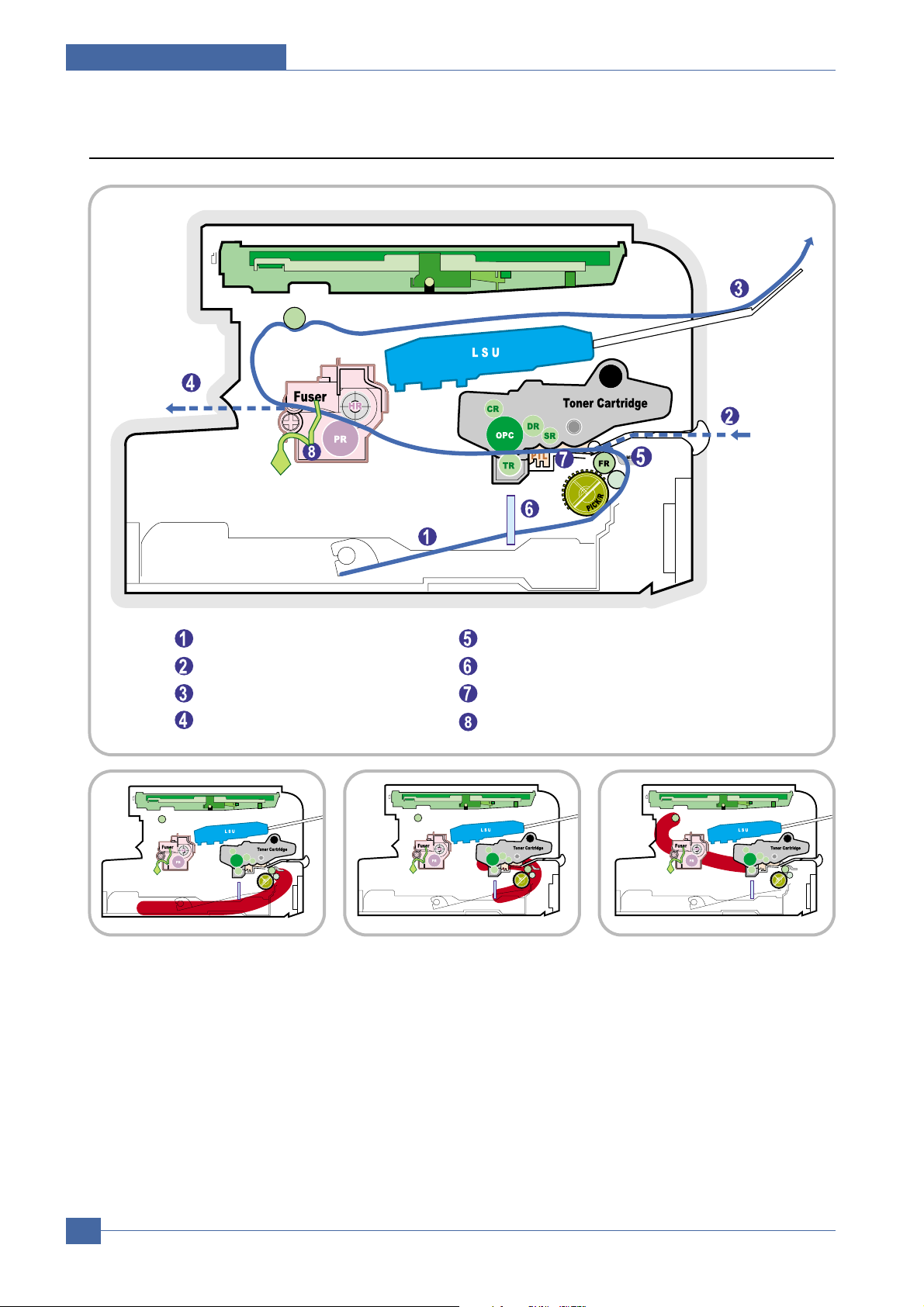
4.2 Paper Path
SCAN PART
Paper Input (Cassette)
Paper Input (Manual Feeder)
Paper Out (Face Down)
Paper Empty Sensor (Manual)
Paper Empty Sensor (Cassette)
Paper Feeding Sensor
Paper Exit SensorPaper Out (Face Up)
SCAN PART
SCAN PART
SCAN PART
1) After receiving a print command, the printer feeds paper from the main cassette or manual feeder as required.
2) The paper being fed passes the paper feed sensor. (Jam 0 occurs if the sensor is not operated within a certain
time)
3) Having passed the paper feed sensor the paper moves to the paper exit sensor via printing process. (Jam 1
occurs if the sensor is not operated within a certain time)
4) The paper then passes through the paper exit sensor and out of the set. (Jam 2 occurs if the trailing edge of the
paper does not pass the exit sensor within a certain time of the paper leading edge activating the exit sensor)
<Jam0> <Jam1> <Jam2>
Page 3

Alignment and Adjustmens
Samsung Electronics
Service Manual
4-3
4.3 Clearing Paper Jams
When a paper jam occurs, "Paper Jam" appears on the display . Refer to the table below to locate and clear the paper jam.
To avoid tearing the paper, pull the jammed paper out gently and slowly. Follow the steps on the next pages to clear the jam.
Message Location of Jam
PAPER JAM 0 OPEN/CLOSE DOOR In the paper tray
PAPER JAM 1 OPEN/CLOSE DOOR In the paper exit area
PAPER JAM 2 CHECK INSIDE In the fuser area or around the toner cartridge
BYPASS JAM In the manual feeder
1 Open and close the front cover. The jammed paper
is automatically ejected from the machine. If the
paper is not ejected continue to step 2.
2 Pull the paper tray open.
3 Remove the jammed paper by gently pulling it
straight out.
If there is any resistance and the paper does not
move when you pull or if you cannot see the paper
in this area, skip to the fuser area around the toner
cartridge. See page 6-5
4 Insert the paper tray into the machine until it snaps
into place.
5 Open and close the front cover to resume printing.
4.3.1 In the Paper Tray
Page 4
Samsung Electronics
Service Manual
Alignment and Adjustmens
4-4
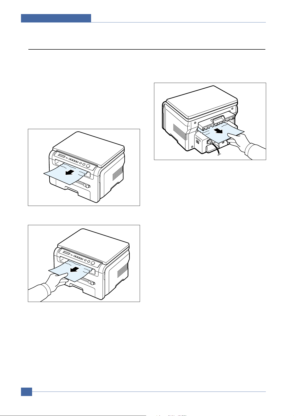
1 Open and close the front cover. The jammed paper
is automatically ejected from the machine. If the
paper is not ejected continue to step 2.
2 Gently pull the paper out of the front output tray.
Skip to step 9.
If you cannot see the jammed paper in the front
output tray, continue to step 3.
3 Open the jam cover by lifting the front edge of the
scanner unit. The support lever will automatically
pop up.
4 Pull the paper out gently.
5 Close the jam cover by pushing the support tab to
the left and hold it down whilst lowering the cover
carefully until the cover fully down, this will hold
down the tab.
If there is any resistance and the paper does not
move when you pull or if you cannot see the paper
in the jam cover, continue to step 6.
6 Open the rear cover.
7 Remove the jammed paper by gently pulling it
straight out.
8 Close the rear cover.
9 Open and close the front cover to resume printing.
4.3.2 In the Paper Exit Area
Page 5

Alignment and Adjustmens
Samsung Electronics
Service Manual
4-5
NOTE: The fuser area is hot. T ake care when removing
paper from the machine.
1 Open the front cover and lightly push down on the
cartridge then pull to take it out.
2 Remove the jammed paper by gently pulling it
straight out.
3 Replace the toner cartridge and close the front
cover.
Printing automatically resumes.
4.3.3 In the Fuser Area or Around the Toner Cartridge
“Bypass Jam” appears on the display when you try to
print using the manual feeder and the machine does
not detect paper, due to no paper or improper paper
loading.
The error message may also occur when the paper is
not properly fed into the machine through the manual
feeder.
In that case, pull the paper out of the machine.
4.3.4 In the Manual Feeder
Page 6

Samsung Electronics
Service Manual
Alignment and Adjustmens
4-6
4.4 Printing the System Data List
Your machine can print the system data report which shows the status of the user-selectable options. You may print this
list to confirm your changes after changing any settings.
To print the system data list:
1 Press Menu until "Report" appears on the top line of the display.
"System Data" appears on the bottom line.
2 Press Start
The system data list prints out.
4.5 Clearing the Memory
You can selectively clear information stored in your machine’s memory.
1 Press Menu on the control panel until "Maintenance" appears on the top line of the display.
2 Press the scroll button ( < or > ) until you see "Clear Settings" on the bottom line and press Start
The first available menu item, “Paper Setting” displays on the bottom line.
3 Press the scroll button ( < or > ) until you see the item you want to clear.
• Paper Setting: Restores all of the Paper Setting options to the factory default.
• Copy Setup: Restores all of the Copy Setup options to the factory default.
• All Settings: Resets all of your settings to the factory default.
• Machine Setup: Resets all of the system settings, such as the display language and save modes, to the factory
default.
4 Press Start/Enter. The selected memory is cleared and the display asks you to continue clearing the next item.
5 To clear another item, press Start/Enter and repeat steps 3 and 4. Or, to return to Standby mode, press Stop/Clear.
4.6 Clearing the Drum
If there are streaks or spots on your print, the OPC drum of the cartridge may require cleaning.
1 Before carrying out the cleaning procedure, make sure that paper is loaded in the machine.
2 Press Menu on the control panel until "Maintenance" appears on the top line of the display.
The first available menu item, "Clean Drum", displays on the bottom line.
3 Press Start
4 When the display asks you to confirm your selection, press Start
The machine prints a cleaning page. Toner particles on the drum surface are affixed to the paper.
5 If the problem remains, repeat steps 1 through 4.
Page 7

Alignment and Adjustmens
Samsung Electronics
Service Manual
4-7
COMPONENT REPLACEMENT CYCLE
Pick-up Roller 50,000 Pages
Paepr Feeding Roller(Friction Pad) 50,000 Pages
Transfer Roller 50,000 Pages
Fuser 50,000 Pages
Toner Cartridge Original 1,000 Pages Replacement 3,000 Pages
4.7 Consumables and Replacement Parts
The cycle period outlined below is a general guideline for maintenance.
The example list is for an average usage of 50 transmitted and received documents per day.
Environmental conditions and actual use will vary these factors.
The cycle period given below is for reference only.
LCD Meaning Solutions
Door Open
[JAM 1] or
[No Cartridge]
Low Heat Error
Open Heat Error
[Over Heat]
[LSU Error]
No Paper
[Add Paper]
Paper Jam 0
Open/Close Door
Paper Jam 1
Open/Close Door
Paper Jam 2
Check Inside
The front or rear cover is not securely
latched.
The toner cartrige is not installed.
There is a problem in the fuser unit.
A problem has occurred in the LSU
(Laser Scanning Unit).
The paper tray has run out of paper.
Paper has jammed in the feeding area of
the paper tray.
• Paper has jammed in the fuser area.
• Apaper jam has occurred in the manual
feeder or the machine detects nonfeeding from the manual feeder.
Paper has jammed in the paper exit area.
Close the cover until it locks into place.
Install the toner cartridge.
Unplug the power cord and plug it back in.
(Tech Mode Reference)
Unplug the power cord and plug it back in.
(Tech Mode Reference)
Load paper in the paper tray.
Clear the jam.
• Clear the jam.
• Clear the jam.
Clear the jam.
4.8 The LCD Status Display by Each Error
Page 8

Samsung Electronics
Service Manual
Alignment and Adjustmens
4-8
4.9 Periodic Defective Image
If a mark or other printing defect occurs at regular intervals down the page it may be caused by a damaged or
contaminated roller. Measure the repetition interval and refer to the table below to identify the roller concerned.
No Roller Defective image Typical defect
1 OPC Drum 75.5mm white spot on black image or black spot
2 Charge Roller 37.8mm black spot
3 Supply Roller 44.9mm light or dark horizontal image band
4 Developing Roller 35.2mm horizontal image band
5 Transfer Roller 45.3mm image ghost
6 Heat Roller 64.0mm Black spot and image ghost
7 Pressure Roller 75.3mm black spot on the backside
SCAN PART
PTL
1
3
7
5
MP Sensor
1
2
3
4
OPC Drum
Charge Roller
Supply Roller
Developing Roller
5
6
7
Tramsfer Roller
Heat Roller
Pressure Roller
<Rollers Layout>
Page 9

Alignment and Adjustmens
Samsung Electronics
Service Manual
4-9
4.10 Error Message
Display Meaning Suggested solutions
Door Open The front cover is not securely latched. Close the cover until it locks into place.
Hsync Error A problem has occurred in the LSU
(Laser Scanning Unit).
Unplug the power cord and plug it back in. If the
problem persists, please call for service.
[Invalid
Cartridge]
There is invalid foner install. Installed authorized toner cartridge.
Low Heat Error There is a problem in the fuser unit. Unplug the power cord and plug it back in. If the
problem persists, please call for service.
[LSU Error] A problem has occurred in the LSU
(Laser Scanning Unit).
Unplug the power cord and plug it back in. If the
problem persists, please call for service.
[No Paper]
Add Paperr
The paper in the paper input tray has run
out.
Load paper in the paper input tray.
Open Heat Error There is a problem in the fuser unit. Unplug the power cord and plug it back in. If the
problem persists, please call for service.
[Over Heat] There is a problem in the fuser unit. Unplug the power cord and plug it back in. If the
problem persists, please call for service.
[Paper Jam 0]
Open/Close
Door
Paper has jammed in the feeding area
of the paper input tray.
Clear the jam.
[Paper Jam 1]
Open/Close
Door
Paper has jammed in the fuser area or
in the manual feeder.
Clear the jam.
[Paper Jam 2]
Check Inside
Paper has jammed in the paper exit area. Clear the jam.
Power Failure Power has turned off then on and the
machine’s memory has not been back up.
The job which you were trying to do before the
power failure must be completely re-done.
Scanner Error There is a problem in the scanner unit. Unplug the power cord and plug it back in. If the
problem persists, please call for service.
Page 10

g
g
t
,
A4(
)
p
[
]
o
f
g
p
y
p
1st level
Upper Level -- Upper Level
Left/Ri
ht &&
Enter
Menu 1.Reduce/Enlarge
2.Darkness
3.Original Type
4.Special Copy
5.Toner Save
6.Paper Setting
7.Copy Setup
8.Report 1
9.Machine Setup
0.Maintenance
Tech Mode
2nd level 3rd level 4th level Default Value Descriptions
Enter
ht
LTR,LGL, A4, EXE, Folio, A5,
B5, A6
LTR,LGL, A4, EXE, Folio, A5,
B5
A6
Light/Normal/Dark
Text, Text/Photo,Photo
[Original(100%)]
[A4ױLTR(94%)]
[EXEױLTR(104%)]
50%
150%
200%
[Custom:50-200%]
1-99
Total Pa
e CNT
FLT Scan CNT
Local
Remote
100%
* Default
LTR(US)
A4(EU/AP)
LTR(US)
EU/AP
Normal
Text
1
English Portuguese ( European)
--ඖ 16 Character
Original(100%)
A4ױLTR(94%)
EXEױLTR(104%)
50%
1
150%
200%
Custom:50-200%
Normal
1
Dark
2
Light
3
1Text * Defaul
2 Text/Photo
3Photo
1Off * Default
2Clone
3 Auto Fit
4 2 Sides in 1 pg ID Copy
52 UP
6 Poster
1
On
Off
2
Paper Size
1
Paper Type
2
Default-Change
1
Timeout
2
System Data
Language
1
Power Save
2
USB Mode
3
1
Clean Drum
Clear Settings
2
Data Setup
1
Machine Test
2
3
Re
ort
Left/Ri
Tray Paper
Manual Feed
Plain Paper, Bond,
Transparency, Card Stock,
Labels, Preprinted, Colored,
Envelope,Thick, Thin
Darkness
Original Type
Reduce/Enlarge 100%
Co
ies
15,30,60,180 sec, Off 30 sec
[English/French/Spanish/P
rtuguese/German/Italian/D
utch/Russian/Swedish]- 9
countries
On 5, 10, 15, 30, 45 5 min
Of
Fast, Slow Fast
Paper Setting
Copy Setup
All Settings
Machine Setup
Clear All Mem.
Clear Count
Flash Upgrade
Switch Test
Dram Test
Rom Test
Pattern Test
Shading Test
stem Data
S
DIRECT KEY
Copies
Menu
Start
Sto
ڪڦ
ඔ/ඖ
Service Manual
4-10
1-99 * Default : 1
This is to be used to enter the Menu.
This key is used to activate the job.
This key is used to stop the job being done or to exit from the Menu. And clear value of 5 copy keys..
This key is used to select the right item what customer wants from several items.
Left/Right Arrow Key
Samsung Electronics
Page 11

;ΒΔΙΚΟΖͺ͵ͽͶΕΤΚΡΝΒΪ
͵ͺͶʹ΅ͼͶΊ
ڭڠڜڟڴ
ٻٻٻڌڋڋڀٻٻٻٻٻٻٻٻٻګډڌ
ڌډڞڪګڴٻڟڤڭڠڞگٻڦڠڴ
notice
ڤۉٻۀڼھۃٻڧڞڟٻڿۄێۋۇڼ۔ٻ ڞڪګڴٻٻٻٻٻٻٻٻٻٻٻٻڌڊڌڋ
ڤہٻېێۀۍٻۋۍۀێێٻڮۏڼۍۏڊڠۉۏۀۍٻۆۀ۔ ٻٻٻٻٻٻٻٻٻٻٻٻٻٻٻٻٻګډڌ
;ΒΔΙΚΟΖΤΥΒΣΥΤΔΠΡΪ
ڤۉٻۀڼھۃٻڧڞڟٻڿۄێۋۇڼ۔ٻ Ready
ڤہٻېێۀۍٻۋۍۀێێٻڮۏۊۋڊڞۇۀڼۍ 100% P.1
ڇڨڼھۃۄۉۀٻێۏۊۋێٻھۊۋ۔
ڞۊۋۄۀێ ڞۊۋۄۀێ ڞۊۋۄۀێ
LCD Display
ڶڌڈڔڔڸڙں 3*4KEY ڶڌڈڔڔڸڙڌڋں ENTER 100% P.10
ڍډڞڪڨڨڪکٻڟڤڭڠڞگٻڦڠڴ
ڮگڪګ Ready
notice
Menu
Start
Stop
ڪڦ
ඔ/ඖ
100% P.1 ΄΅ʹͽͶͲ
ګۇۀڼێۀٻڲڼۄۏ೨
ڞۇۀڼۍٻڦۀ۔ٻڱڼۇېۀ
ͺΞΒΘΖʹΠΟΥΣΒΤΥͿΠΗʹΠΡΚΖΤΖΕΦΔΖͶΟΝΒΣΘΖ΄ΡΖΔΚΒΝ
ΖΥΦΣΟΕΖΗΒΦΝΥΧΒΝΦΖΠΗΒΝΝΔΠΡΪΜΖΪΤ
This is to be used to enter the Menu.
This key is used to activate the job.
This key is used to stop the job being done or to exit from the Menu. And clear value of 5 copy keys..
This key is used to select the right item what customer wants from several items.
Left/Right Arrow Key
ڎډڮۏڼۏېێٻڧڠڟ
ͺΕΝΖ͵ΚΤΡΝΒΪ Ready
LED Color LED Status
ΗΗ ΗΗ
Green
Ο
ͳΝΚΟΜ
ΖΕ
Ο
ͳΝΚΟΜ
ΠΨΖΣΗΗ΄ΝΖΖΡ;ΠΕΖ
Discription
ΖΒΕΪ
ΈΙΖΟΥΙΖΛΠΓΚΤΚΟΡΣΠΘΣΖΤΤ
ͳΝΚΟΜ΄ΝΠΨΝΪΣΚΟΥΖΣ͵ΒΥΒʹΠΞΞ
ͳΝΚΟΜͷΒΤΥΣΚΟΥΚΟΘ
ͳΝΚΟΜͿΠΣΞΒΝΝΪʹΠΡΪ΄ΔΒΟ
ΖΩ΅ΠΟΖΣͶΞΡΥΪΒΡΖΣͻΒΞΒΡΖΣͶΞΡΥΪʹΠΧΖΣ
ΠΡΖΟ
ͺΟΔΒΤΖΠΗΣΖΔΠΧΖΣΒΓΝΖͶΣΣΠΣ
ΖΩΒΡΖΣ;ΚΤΞΒΥΔΙΚΟΘ
ͺΟΔΒΤΖΠΗΈΒΣΞΚΟΘΦΡΤΥΒΥΖ
ΖΩΖΡΝΒΔΖ΅ΠΟΖΣ
Samsung Electronics
Service Manual
4-11
 Loading...