

Page 1
System Overview
Samsung Electronics
Service Manual
3-1
3
3
3. System Overview
This chapter describes the functions and operating principles of the main components.
3.1 System Outline
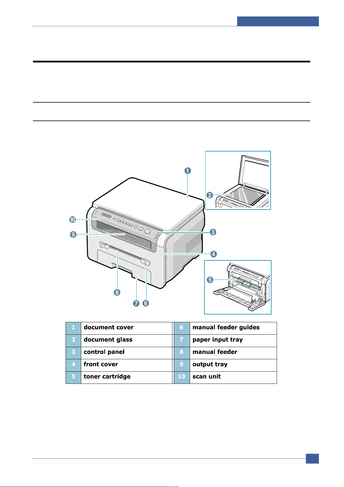
3.1.1 Front View
Page 2
Samsung Electronics
Service Manual
System Overview
3-2
3.1.2 Sensor
Page 3
System Overview
Samsung Electronics
Service Manual
3-3
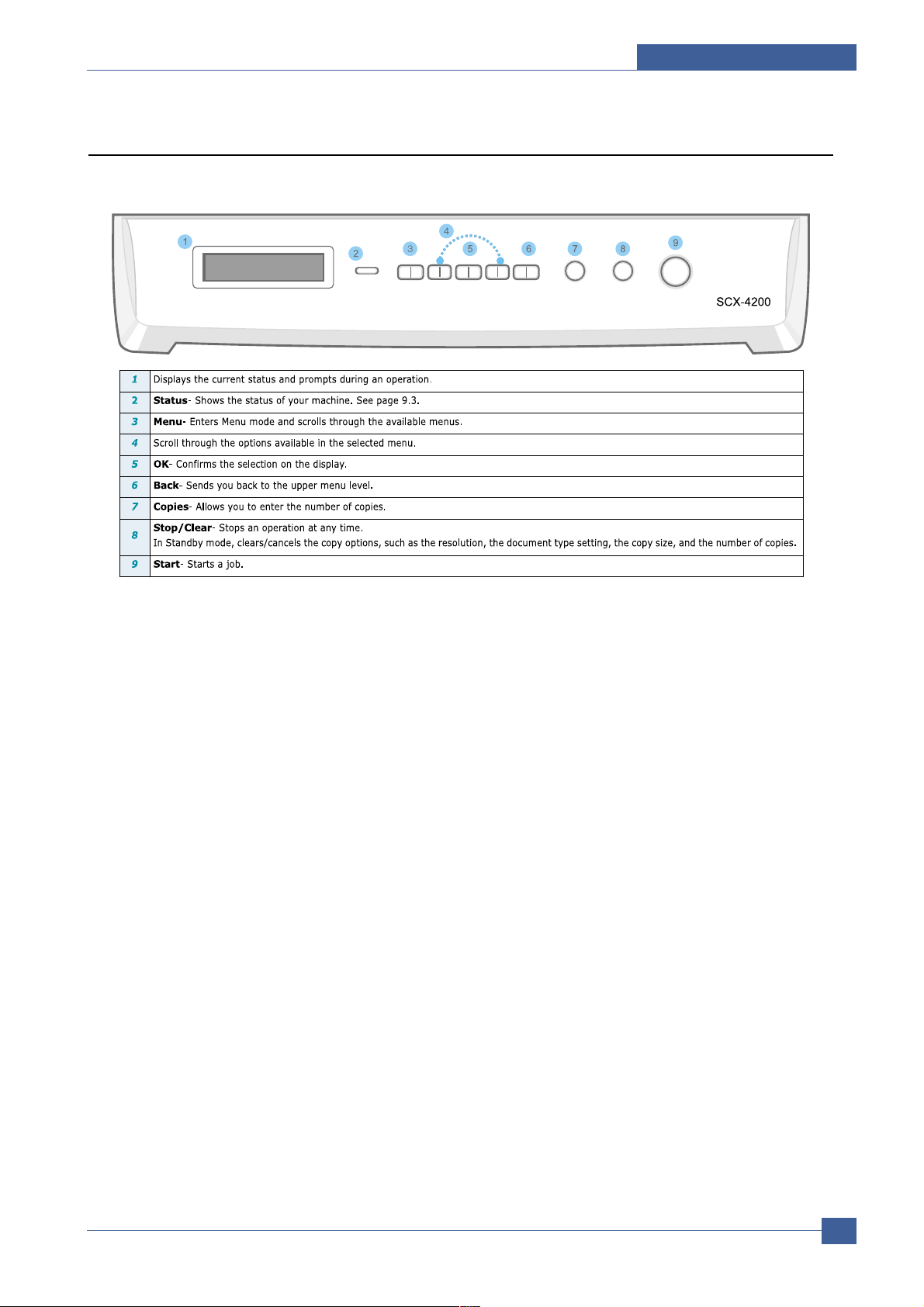
3.1.3 Control Panel
Page 4
Samsung Electronics
Service Manual
System Overview
3-4
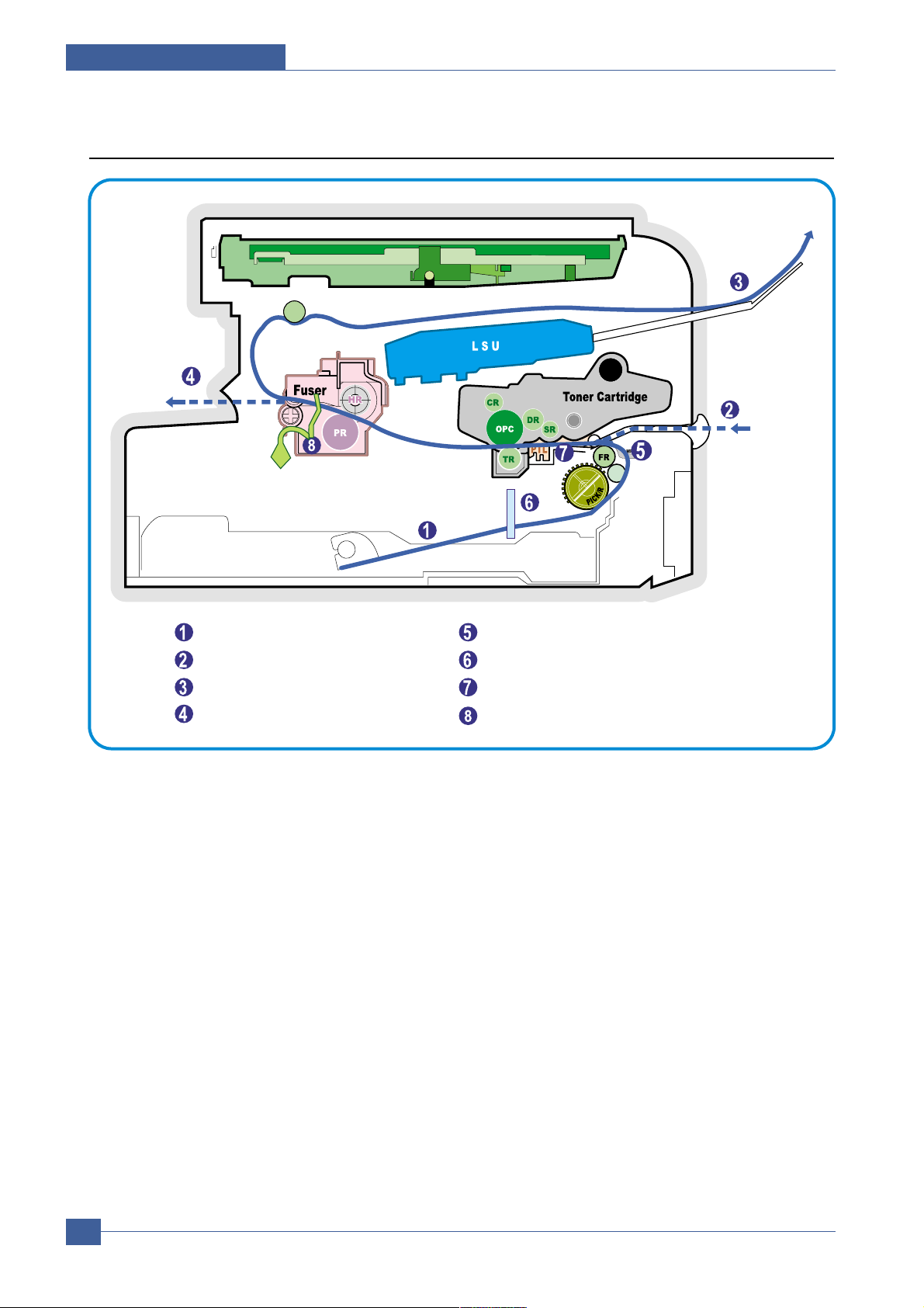
3.1.4 System Layout
SCAN PART
Paper Input (Cassette)
Paper Input (Manual Feeder)
Paper Out (Face Down)
Paper Empty Sensor (Manual)
Paper Empty Sensor (Cassette)
Paper Feeding Sensor
Paper Exit SensorPaper Out (Face Up)
Page 5

System Overview
Samsung Electronics
Service Manual
3-5
3.1.4.1 Paper Feed Mechanism
The printer has a universal cassette which automatically loads paper and a manual feed which supplies paper
single sheet at a time. The cassette has a friction pad which separates paper to ensure single sheet feeding, and it
has a sensor, which checks when the paper tray is empty.
- Feeding Method: Universal Cassette Type
- Feeding Standard: Center Loading
- Feeding Capacity: Cassette-250 sheets (75g/m2 , 20lb paper standard)
Manual 1 sheet (Paper, OHP, Envelop, etc.)
- Paper detecting sensor: Photo sensor
- Paper size sensor: None
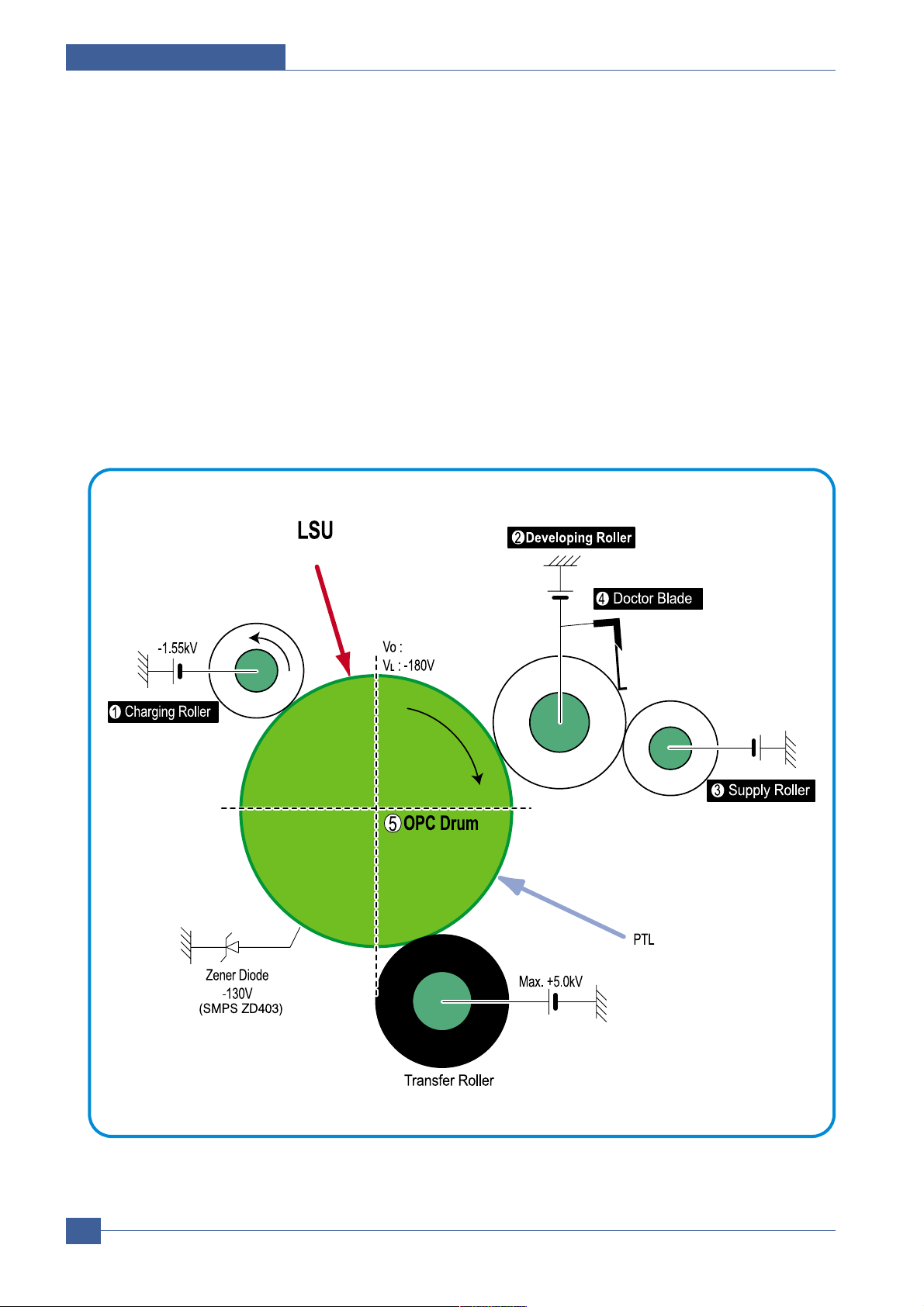
3.1.4.2 Transfer Ass’y
This consists of the PTL (pre-transfer lamp) and the Transfer Roller. The PTL shines a light onto the OPC drum.
This lowers the charge on the drum’s surface and improves transfer efficiency.
The transfer roller transfers toner from the OPC drum surface to the paper.
- Life expectancy: Over 50,000 sheets (at 15~30°C)
3.1.4.3 Drive Ass’y
A gear driven power unit. The motor supplies power to the paper feed unit, the fuser unit, and the toner cartridge.
3.1.4.4 Fixing Part(Fuser)
Heat Lamp type used on 220V Export models and all 110V models.
The Heat Lamp type fuser consists of the Heat Lamp, Heat Roller, Pressure Roller, Thermistor, and Thermostat. It
fixes toner to the paper using pressure and heat to complete the printing job.
1)Heat Lamp power cut-off (Thermostat)
The thermostat is a temperature sensing device, which cuts off the power to the heat lamp to prevent overheating
fire when the heat lamp or heat roller overheats.
2)Temperature Detecting Sensor (Thermistor)
The Thermistor detects the surface temperature of the heat roller, this information is sent to the main processor
which uses this information to regulate the temperature of the heat roller.
3) Heat Roller
The surface of the Heat Roller is heated by the Heat Lamp. As the paper passes between the Heat and Pressure
rollers the toner is melted and fixed permanently to the paper. The surface of the roller is coated with Teflon. This
ensures that toner does not adhere to the roller surface.
Page 6

Samsung Electronics
Service Manual
System Overview
3-6
4) Pressure roller
The Pressure Roller mounted under the heat roller, it is made of a silicon resin, and the surface of the roller is
tubed with Teflon. This ensures that toner does not adhere to the roller surface.
5) Safety Relevant Facts
• To prevent overheating
- 1st protection device: Hardware cuts off when overheated
- 2nd protection device: Software cuts off when overheated
- 3rd protection device: Thermostat cuts off mains power to the lamp.
• Safety device
- Fuser power is cut off when the front cover is opened
- LSU power is cut off when the front cover is opened
- The temperature of the fuser cover's surface is maintained at less than 80ºC to protect the user and a
caution label is attached where the customer can see it easily when the rear cover is opened.
3.1.4.5 Scanner Unit
• Scan Image Controller
1.Scan Line Time : 1.63ms
2.Scan Resolution : Color : Max 600DPI
3.Scan Width : 216mm
4.Function
- White Shading Correction
- Gamma Correction
- CIS Interface
- 256 Gray Scale
•
CIS Operating Part: CIS use +3.3V
- CIS Max Operating Freguency: 5MHz
Page 7
System Overview
Samsung Electronics
Service Manual
3-7
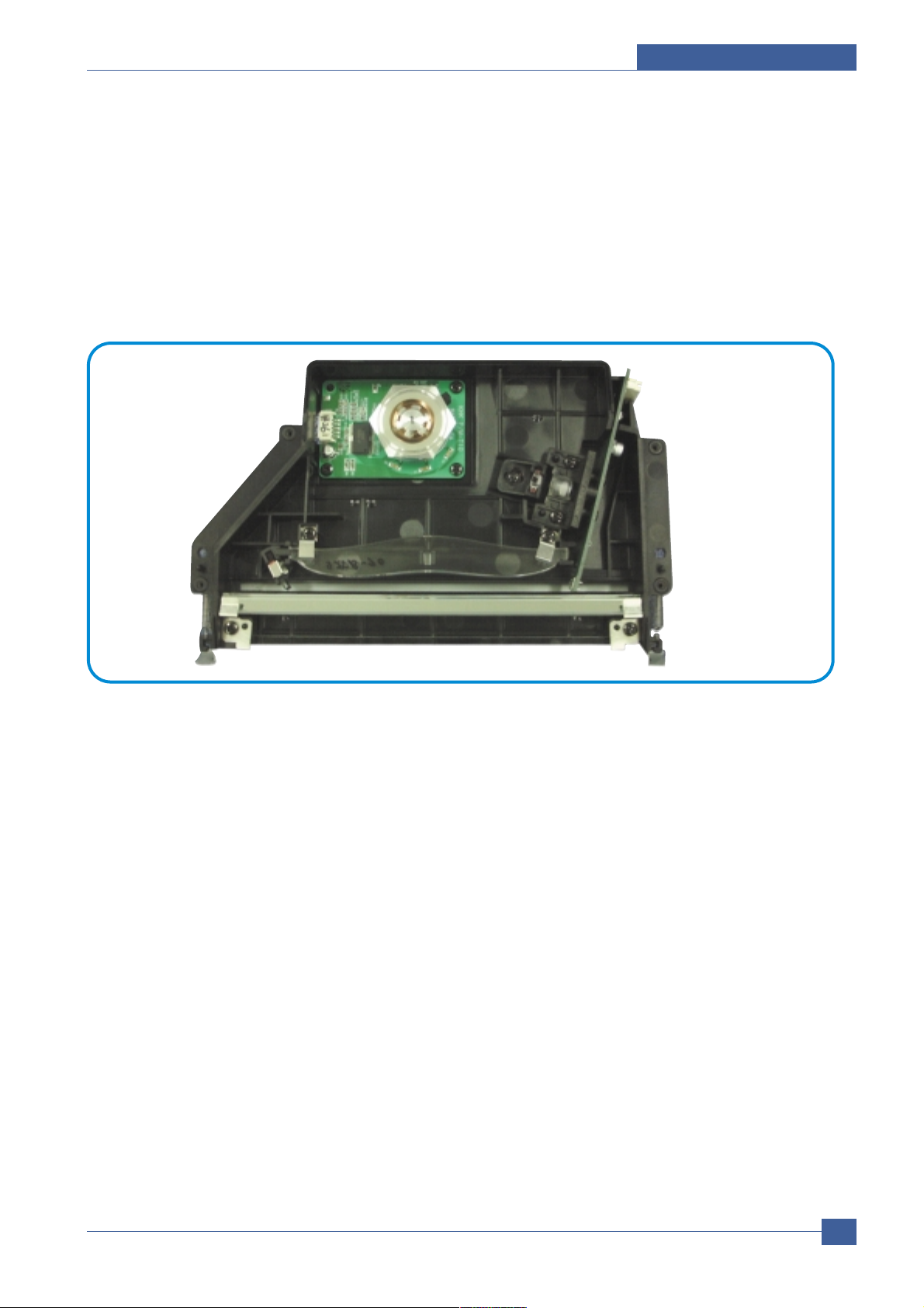
3.1.4.6 LSU (Laser Scanner Unit)
This is the core of the laser printer. It converts the video data received from the computer into an electrostatic
latent image on the surface of the OPC drum. This is achieved by controlling the laser beam and exposing the
surface of the OPC drum to the laser light. Arotating polygon mirror reflects the laser light onto the OPC and each
side of the mirror is one scan line. The OPC drum turns as the paper feeds to scan the image down the page.
The /HSYNC signal is created when the laser beam from LSU reaches the end of the polygon mirror and this
signal is sent to the controller. The controller detects the /HSYNC signal to adjust the vertical line of the image on
paper. In other words after the /HSYNC signal is detected the image data is sent to the LSU to adjust the left margin
on the paper.
Page 8
Samsung Electronics
Service Manual
System Overview
3-8
3.1.4.7 Toner Cartridge
The toner cartridge is an integral unit containing the OPC unit and toner unit. The OPC unit consists of the OPC
drum and charging roller, and the toner cartridge unit consists of the toner, supply roller, developing roller, and
blade (Doctor blade)
- Developing Method: Non magnetic 1 element contacting method
- Toner: Non magnetic 1 element shatter type toner
- The life span of toner: 3,000 sheets (ISO standard)
- Toner remaining amount detecting sensor: No
- OPC Cleaning: Electrostatic process
- Management of waste toner: Electro static process(Cleanerless Type)
- OPC Drum protecting Shutter: No
- Classifying device for toner cartridge: ID is classified by interruption of the frame channel
0.22mW
-970V
-430V
-580V
Page 9

System Overview
Samsung Electronics
Service Manual
3-9
3.2 H/W Structure and Descriptions
SCX-4200 is roughly made up Main Control part, Operation Panel part, Scanner part, PC interface part and
Power part. Each Part is separated Module which focus on common and standard design of different kind products.
The main control part is 1 CPU,1 board adopting Chorus 2 Chip which is exclusive MFP ASIC . Scanner part is
composed Platen and is connected with Main Cantroller by Harness.
3.2.1 CPU Part
1) CPU : Use 16/32Bit RISC Processor, Chorus 2,which is exclusive controller to execute Printer and to execute
operation block by flash memory within system program, and to control whole system.
- Main function block
- Completely Integrated System for Embedded Applications,
- 16/32 Bit Risc Architecture, Efficient and Powerful ARM7 Core.
- LSU Interface Module for Interfacing PVC with LSU
- 5 Channel General Purpose DMA Controllers for High Speed I/O
- Operation Frequency: System: 66MHz, Bus: 66MHz
- Operation Voltage : 3.3V
2) Flash Memory : Record System Program, and download System Program by PC INTERFACE..
- Size: 1M Byte
- Access time: 70 nsec
Page 10

Samsung Electronics
Service Manual
System Overview
3-10
3) SDRAM : is used as Page Buffer in Printing, Scan Buffer in Scanning and System Working Memory Area
- Size: 8Mbyte
- 3.5 MB: System Working Memory Area and Scan Buffer
- 4.5 MB: Printing System Working Memory Area
- Max Frequency: 133MHz
CPU
(
ARM7TDMI)
DMA Controller
(IP_DMAC)
DATA-BUS
Scanner
Analog Signal
Sensor
Control
Signal
MEMORY
CONTROLLER
IP_TOP
DATA-BUS
ADDR-BUS
ADDR-BUS
IP_TOP interface
IP_MAIN
IP_SFR
Motor
Motro
Control
Signal
Page 11

System Overview
Samsung Electronics
Service Manual
3-11
3.2.2 Scan Part
1) Pictorial signal input part: output signal of CIS passes through Bypass Cap change to ADC at IPMain and
defined signal between AFE and IPMain processes the Image signal. When AFE accept each pixel, CDS
(Correlated Double Sampling) technique which samples arm-level twice is used on each pixel by using IP
signal.
2) Pictorial image processing part: read CIS Pixel data in terms of 600dpi Line and process LA Talgorithm on
text mode, Error Diffusion Algorithm on Mixed mode, and store Data at Scan Buffer on PC Scan mode without
algorithm. On every mode Shading Correction and Gamma Correction are executed ahead then processing is
executed later.
* Scan Image Control Specification
Minimum Scan Line Time: 1.23ms
Scan Resolution: Max. 600 x 2400 DPI (optical)
Scan Width: 216mm
main function
- Internal 10bit ADC
- White Shading Correction
- Gamma Correction
- CIS Interface
- 256 Gray Scale
3) CIS Operating Part : CIS use +3.3V
- CIS Maximum Operating Frequency : 5MHz
- CIS Line time : 1.63ms
- White Data output Voltage : 1.7V -(Mono Copy, 5ms/line)
3.2.3 Ope Pannel
1) Configuration
Operation Panel uses Main Control and separated Ope Chip Micom and work as inner program, systemic
operation is serial system which exchange Data with SIO Port of Main Control. Ope Panel is approximately
composed of Micom part, Matrix part and LCD.
2) Micom controller
Micom has ROM, RAM, I/O Port built-in and displays and lights LCD by CPU command of Main Control Part
and report Key recognition Data to Main Control Board.
Page 12

Samsung Electronics
Service Manual
System Overview
3-12
3.2.4 Printer Section
Printer is consisted of the Engine parts and F/W, and said engine parts is consisted of the mechanical parts
comprising Frame, Feeding, Developing, Driving, Transferring, Fusing, Cabinet and H/W comprising the main
control board, power board, operation panel, PC Interface.
The main controller is consisted of Asic(Chorus2) parts, Memory parts, Engine.
Interface parts and it functions as Bus Control, I/O Handling, drivers & PC Interface by CPU.
Memory Access supports 16bit Operation, and Program Memory 1MB and Working Memory as well.
The Engine Board and the Controller Board are in one united board, and it is consisted of CPU part and print part
in functional aspect. The CPU is functioned as the bus control, I/O handling, drivers, and PC interface. The main
board sends the Current Image, Video data to the LSU and manages the conduct of Electrophotography for
printing. It is consisted of the circuits of the motor (paper feed, pass) driving, clutch driving, pre-transfer lamp
driving, current driving, and fan driving.
The signals from the paper feed jam sensor and paper empty sensor are directly inputted to the main board.
3.2.4.1 ASIC
Chorus 2
- 16/32-bit RISC embedded processor core
- 4KB instruction cache and 4KB data cache
- No Tightly Coupled Memory
- Memory Protection Unit & CP15 control program
Printer Video Controller for LBP engines
Graphic Execution Unit for banding support of Printer Languages
Printer Video Controller for LBP engines
- PVC: Printer Video Controller without RETAlgorithm
Engine Controller
- Motor Control Unit
- Motor Speed Lookup Table Memory (128 x 16 x 2)
- Pulse Width Modulation Unit
- 2 Channels are supported
- ADC Interface Unit
- 2 ADC Channels are available
- ADC Core maximum clock frequency: 2.5 MHz
USB 2.0 Interface
Package : 208-LQFP-2828
Power : 1.8V(Core), 3.3V(IO) power operation
Speed : 66MHz core(ARM7TDMI) operation, 60MHz bus operation
Page 13

System Overview
Samsung Electronics
Service Manual
3-13
Boundary Scan
ARM7TDMI TAP
Controller
General Purpose I/O
Bus Arbiter
Write
Buffer
ARM7TDMI
CPU Core
Cache
4K Byte
CPU Unit
System Timer
(4-ch)
GPIO
Controller
Watchdog Timer
10bit ADC
Rotator
RTC
(Real Time Clock)
JTAG
AIN[3:0]
General DMA
(2-CH)
Interrupt
Controller
Memory I/F ROM/
SRAM
DRAM/SDRAM
IP_TOP
SSB
USB v1.1
UART (2-ch)
HP SIO
Tone Generator
CRCON
LFCON
CRFIRE
LSU I/F
Parallel Port
(P1284)
System Bus Bridge & Arbitration /
BDMA (2-Ch.)
Clock Generator
(MPLL)
Clock Generator
(UPLL)
PRT_TOP
Clock Generator
(PPLL)
Chorus 2 Block Diagram
Page 14

Samsung Electronics
Service Manual
System Overview
3-14
3.2.5 Copier Part
1) Copy Mode: Black and White
2) Scanner Type: CIS with Flatbed/Platen
3) Maximum Size of Original:
Platen: 216 x 297 mm
(max. width = 216 mm, max length = 297 mm)
4) Optical Resolution: 600 x 600 dpi
5) Copy Quality - H x V:
Text : 600 x 300 dpi (default)
(User selectable via Content button) Mixed : 600 x 300 dpi
Photo : 600 x 600 dpi
6) Supported Media Types: Plain, Label, Cardstock, Transparency
7) Copy Speed: Platen, SDMP: 19cpm (Letter)
(SDMP = Single Document, Multiple Printout)
8) Reduce/Enlarge: Platen: 50% - 200% (1% increments)
9) Non-printable Area: 4 mm (Top, Bottom, and each Side)
10) Copy Count: 1 to 99
(Page count displayed on LCD during copy operation)
11) Copy Modes: Text, Text/Photo, Photo
12) Fixed R/E Setting: 100%, Auto-fit
13) Darkness Control: 3 levels
14) First Copy Output Time (FCOT): Platen: 11 sec. (600 x 300 dpi)
15) Duplex Copy Manual
3.2.6 SMPS & HVPS
The SMPS supplies DC Power to the System.
It takes 110V/220V and outputs the +5V, +24V to supply the power to the main board . The HVPS board creates
the high voltage of THV/MHV/Supply/Dev and supplies it to the developer part for making best condition to display
the image. The HVPS part takes the 24V and outputs the high voltage for THV/MHV/BIAS, and the outputted high
voltage is supplied to the toner, OPC cartridge, and transfer roller.
Page 15

System Overview
Samsung Electronics
Service Manual
3-15
3.2.6.1 HVPS (High Voltage Power Supply)
Transfer High Voltage (THV+)
- Input Voltage : 24 V DC 15%
- Output Voltage : MAX +5.0KV 5 %,(Duty Variable, no loading )
- Input contrast of the Voltage stability degree : under 3 % (fluctuating input 21.6V~26.4V)
Loading contrast :
3 % or less
- Output Voltage Rising Time : 100 ms Max
- Output Voltage Falling Time : 100 ms Max
- Fluctuating transfer voltage with environmental various : +650 V~ 5 KV
- Environment Recognition Control Method : The THV-PWM ACTIVE is transfer active signal. It detects the
esistance by recognizing the voltage value, F/B, while permits the environmental recognition voltage.
- Output Voltage Control Method : Transfer Output Voltage is outputted and controlled by changing Duty of
THVPWM Signal.
Charge Voltage (MHV)
- Input Voltage : 24 V DC 15%
- Output Voltage : -1.3KV ~ -1.8KV DC 3%
- Output Voltage Rising Time : 50 ms Max
- Output Voltage Falling Time : 50 ms Max
- Output Loading range : 30 M ~ 1000 M
- Output Control Signal(MHV-PWM) : CPU is HV output when PWM is Low
Cleaning Voltage (THV-)
- The (+) Transfer Voltage is not outputted because the THV PWM is controlled with high.
- The (-) Transfer Voltage is outputted because the THV-Enable Signal is controlled with low
- The output fluctuation range is big because there is no Feedback control.
- Input Voltage : 24 V DC 15%
- Output Voltage : -1KV 15%
- Output Voltage Rising Time : 100 ms Max
- Output Voltage Falling Time : 100 ms Max
Developing Voltage (DEV)
- Input Voltage : 24 V DC 15%
- Output Voltage: -200V ~ -600V DC 3%
- Output Voltage Fluctuation range: PWM Control
- Input contrast of the output stability degree : 3 % or less
Loading contrast : 3 % or less
- Output Voltage Rising Time : 50 ms Max
- Output Voltage Falling Time : 50 ms Max
- Output Loading range : 10M ~ 1000 M
- Output Control Signal (BIAS-PWM) : the CPU output is HV output when PWM is low.
Page 16

3.2.6.2 SMPS (Switching Mode Power Supply)
It is the power source of entire system. It is assembled by an independent module and completely common use
with SCX-4200, so it is same characteristic with SCX-4200. It is mounted at the bottom of the set.
It is consisted of the SMPS part, which supplies the DC power for driving the system, and the AC heater control
part, which supplies the power to fuser. SMPS has two output channels. Which are +5V and +24V.
AC Input
- Input Rated Voltage: AC 220V ~ 240V AC 110V ~ 127V
- Input Voltage fluctuating Range: AC 198V ~ 264V AC 99V ~ 135V
- Rated Frequency: 50/60 Hz
- Frequency Fluctuating Range: 47 ~ 63 Hz
- Input Current: Under 5.0Arms / 2.5Arms (But, the status when lamp is off or rated voltage is inputted/outputted )
Rated Output Power
NO ITEM CH1 CH2 CH3 Remark
1 CHANNEL NAME +5V +24V +24.0VS
2 CONNECTOR PIN CON2 CON 2 CON 2
5V PIN 3, 4, 24 24V PIN:13 24VS PIN:11, 12
GND PIN 5,6 GND PIN:7, 9, 10 GND PIN:7, 9, 10
3 Rated Output +5V
5% +24V-10/15% +24VS-10/15%
(4.75~5.25V) (21.6~27.6V) (21.6~27.46V)
4 Max. Output current 1.0A 0.5 A 1.0 A
5 Peak Loading voltage 1.5A 1.0 A 1.5 A 1ms
6 RIPPLE NOISE Under 150m Vp-p Under500mVp-p Under 500mVp-p
Voltage
7 Maximum output 5.0W 12W 24W
Samsung Electronics
Service Manual
System Overview
3-16
Supply
- Output Voltage : -400 V ~ -800V DC 5%(ZENER using, DEV )
- Input contrast of the output stability degree : under
3 %
Loading contrast :
5 % or less
- Output Voltage Rising Time: 50 ms Max
- Output Voltage Falling Time: 50 ms Max
- Output Loading Range: 10 M ~ 1000 M
- Output Control Signal (BIAS-PWM): the CPU is HV output when PWM is low.
Page 17

System Overview
Samsung Electronics
Service Manual
3-17
Consumption Power
Length of Power Cord : 1830 50mm
Power Switch: Use
Feature
- Insulating Resistance: 100 or more (at DC 500V)
- Insulating revisiting pressure: Must be no problem within 1 min. (at 1,000V-LV / 1,500Vac-HV,10mA)
- Leaking Current: under 3.5mA
- Running Current: under 40A PEAK (AT 25 , COLD START)
under 60A PEAK (In other conditions)
- Rising Time: within 2Sec
- Falling Time: over 20ms
- Surge : Bi-Wave 3kV(2 ) - Normal, 6KV(12 ) - Common
Environment Condition
- Operating Temperature Range: 0 ~ 40
- Maintaining Temperature Range: -25 ~ 85
- Preserving Humidity Condition: 30% ~ 90% RH
- Operating Atmospheric Pressure Range: 1atm
EMI Requirement: CISPR, FCC, CE, MIC
Safety Requirement: IEC950 UL1950, CSA950, C-UL, Semko, CB, CCC(CCIB),GOST, EPA, Power Save
NO ITEM CH1(+5V) CH2(+24V) CH3(+24VS) System
1 Stand-By 0.2A 0.07A 0.07 A AVG : 100 Wh
2 PRINTING 1.0A 0.5A 1.0 A AVG 350 Wh
3 Sleep-Mode 0.2A 0.02A 0.03A AVG : 10 Wh
Page 18

Samsung Electronics
Service Manual
System Overview
3-18
3.2.7 FUSER AC POWER CONTROL
Fuser(HEAT LAMP) gets heat from AC power. The AV power controls the switch with the Triac, a semiconductor
switch. The ‘ON/OFF control’ is operated when the gate of the Triac is turned on/off by Phototriac (insulting part).
In other words, the AC control part is passive circuit, so it turns the heater on/off with taking signal from engine
control part.
When the ‘HEATER ON’signal is turned on at Engine, The LED of PC102 (Photo Triac) takes the voltage and flashes. From the flashing light, the Triac part (light receiving part) takes the voltage, and the voltage is supplied to the
gate of Triac and flows into the Triac. As a result, the AC current flows in the heat lamp, and heat is occurred.
On the other hand, when the signal is off, the PC102 is off, the voltage is cut off at the gate of Triac, the Triac
becomes off, and then the heat lamp is turned off.
Triac (THY1) feature :12A, 600V SWITCHING
Phototriac Coupler (PC102)
- Turn On If Current : 15mA~ 50mA(Design: 16mA)
- High Repetive Peak Off State Voltage : Min 600V
Page 19

System Overview
Samsung Electronics
Service Manual
3-19
3.3 S/W Structure and Descriptions
3.3.1 Architecture
The following diagram shows the Engine Control System.
Fig 1. The architecture of the engine firmware
Fuser Unit
LSU
HVPS
Fan Unit
Motors
Solenoid &
Clutch
Main F/W of the printer controller
Engine Firmware
Power On
Print Interface Control Module
Engine Print Processing
Control Module
Engine Unit Control Module
Initial
Device Units
Hardware Devices
& Mechanical Device
Sensors signals
Page 20

Samsung Electronics
Service Manual
System Overview
3-20
3.3.2 S/W Overview
Engine Control F/W is executed every 10msec by the timer interrupt of the main system.
And it consists of 4 control modules. Power on Initial, Engine Print Processing Control, Print Interface Control and
Engine Unit Control Module. Major operations of the Printer Engine Control F/W are following.
- Control the Pick-Up, Feeding and Discharging of Paper
- Control the LSU
- Control the HVPS for the Developer Process
- Control the Temperature of Fuser unit
- Control the Motor
3.3.2.1 Power on Initial Module
If it turns on the power of the printer , the main f/w calls this module of the engine first. And so the printer engine control firmware executes the necessary initialization. After that, the other modules of the printer engine control firmware
are called and executed. Specially, in this module H/W ports or variables related to critical action must be initialized.
3.3.2.2 Engine Print Processing Control Module
The main control module largely consists of 4 sub functions. First function is that processes virtual timer jobs, second function does a Time Processing for checking elapsed time and counter, the third function is that is doing jam
processing and final function is that doing state processing for the each engine state.
- Virtual timer function: This is about the virtual timer used to control time process in the engine part. This
consists of three parts. One is the action part to declare ID and Function, another is the execution part to
run the timer and the function and the other is the stop part to stop the timer. This controls the process unit
as time.
- Time Processing function: This is function that processes a timer for counter, elapsed time after on time.
- Jam Processing function: It checks the jam state under conditional status.
- State processing function: This is about the processing of the engine status. This controls the printer
according to the state of the engine. These states consist of many states according to the engine mode.
3.3.2.3 Print Interface Module
Print Interface Control Module communicates with the main system for receiving the command from main system
and transmitting the present status of engine for requested status. There are several sub functions. One is a function for receiving command from the main system. Second is a function that informs the main system of the current
engine status for requested item. And there is function that calls sub-functions for specific operations that is requested by printer controller or printer engine firmware.
Page 21

System Overview
Samsung Electronics
Service Manual
3-21
3.3.2.4Engine Unit Control Module
Engine Unit Control Module consists of 4 sub-functions. The first function is a fixing unit control function. At this function, it controls the temperature of a fixing unit for regulating temperature of the unit within a fixed range that is set
following paper type and number of printout. The second function is a fan control function that controls operation of
fan unit. And the third function is a sensor status management function. It gets the present status of each sensor
and sets the status of each sensor . Finally there is a Unit and Device control function. In this function, it controls the
devices and units for example: Motor , Clutch, and so on.
3.3.2.5Paper Size
Eiger does not have a paper size sensor . So the information of the paper size is basically received from the main
system. But the engine measures the paper size with the counter value based on the time of the feed sensor on-off
when the paper is fed. We obtain the interval distance between paper and paper in the information from the main
system and the measured interval distance. Comparing two interval distances, we choose the paper size with which
the paper has a larger interval distance. The default value of the paper size is a legal.
3.3.2.6Paper Type
The information of paper type is sent by the main system. The engine considers following paper types.
Plain Paper OHP
Envelope Card Stock
Label Thin
Bond Thick
Colored Paper Preprinted
It controls a fuser temperature and a pick-up time according to above paper type. Each control depends on its
mechanism.
Normally, papers with hard thickness are controlled by maintained a high temperature. But a paper like OHP is controlled at the lower temperature.
Page 22

Samsung Electronics
Service Manual
System Overview
3-22
3.3.3 Functional Requirements of Fixing Unit (Fuser) Handling
The fixing control depends on its fixing mechanism. And according to a paper type, a paper size, an elapsed printed
time, or the number of accumulated Printing Pages, a fixing control is different. Moreover, it may be different
according to hardware specs, which are a flicker, an inner temperature and so on.
3.3.3.1 Print Mode
There are warm-up, stand-by, printing, error and sleep mode in the print mode. Every mode is one of major
elements to decide the fixing temperature.
At the warm-up mode, the engine makes the temperature of the fixing unit rise up to the warm-up target temperature,
which is normally the same as the stand-by temperature.
At the stand-by mode, it maintains the specified temperature of the fixing unit in order to reduce the time to print
the first page.
At the printing mode, it controls the temperature of the fixing unit according to the paper type, the paper size, the
number of accumulated printing pages, the elapsed printing time and the environment index.
3.3.3.2 Paper Type
The paper type is also one of major elements to decide the temperature of the fixing unit. According to the paper
type, the temperature is different. Generally, a thick paper has higher temperature and OHP has lower temperature
than a plain paper does. The fixing unit has a different temperature according to the paper type mentioned in
3.1.2.2. Paper Type
3.3.3.3 Paper Size
If the paper width is narrow, the temperature of fuser roller does not uniformly at overall surface of the roller. So in
this case, the engine controls the interval of pick up of the paper.
But because it does not have a sensor for a paper width, it judges whether a paper width is a narrow paper by a
paper length. If it judges a current paper size is below B5, it regards as a narrow paper. Normally, if a paper size is
a narrow, the interval of pick up is lengthened according to an elapsed printing time and the number of accumulated
Printing Pages.
3.3.3.4 Accumulated Printing Pages
If more pieces of paper are printed than the specified number of the paper, the inner temperature of machine may
be saturated. In this case, the engine keeps the temperature of the fixing unit with the specified temperature. The
accumulated printing pages are cleared at the sleep mode.
3.3.3.5 Elapsed Printing Time
If the printing job is done over the fixed time, the inner temperature of machine may be saturated. In this case, the
engine keeps the temperature of the fixing unit with the specified temperature. The elapsed printing time is cleared
at the sleep mode.
Page 23

System Overview
Samsung Electronics
Service Manual
3-23
3.3.3.6Temperature in the Stand-By mode
At the stand-by mode, the engine controls the temperature of the fixing unit for maintaining a specified temperature
for reducing printing time of the first page.
Moreover, the temperature depends on an environment condition. For example, normally the temperature in low
temperature and low marshy place is maintained higher than that in normal temperature and normal marshy place.
3.3.3.7Temperature in the Warm-Up mode
When the engine operates the warm-up processing, it controls the temperature of the fixing unit for raising the
temperature to the stand-by temperature.
3.3.3.8Environmental Index
The engine checks the present environment when it performs the printing job or the warm-up process and then
with the checked result, the temperature of fixing unit is assigned with a different temperature for each mode.
It is very important to control the temperature of the fixing unit in the printing process and there are many requirements for it. Therefore, a Temperature Table is defined and given by the fixing unit team. See the attachment.
Page 24

Samsung Electronics
Service Manual
System Overview
3-24
3.3.4 Functional Requirements for LSU Control
LSU receives the image data from PVC and make the latent image on OPC surface.
It uses the single beam .
The Eiger has many different registers for LSU. These registers are in manual book of CHORUS2, the CPU of the
Eiger.
3.3.4.1 LSU Ready Check
The Eiger will pick up the paper when the LSU is ready. And when the paper picked up meets the feed sensor, it will
check whether the LSU is ready or not and the Hsync is detected or not for appointed time.
3.3.4.2 Sequence of LSU module
The laser scanning unit control is executed when engine control module receives print command.
- Setting up the initial value
- With above results, it controls the polygon motor and laser diode when receives print command.
- With above results, it monitors register value related to LReady and Hsync, and if the error happens, it sets up the
error flag
- If no error happens with above results, set up the values to mask the video data for horizontal and vertical region
but if happens, it will be recovered according to the recovery sequence.
Page 25

System Overview
Samsung Electronics
Service Manual
3-25
3.3.5 Functional Requirements of Environment Recognition
It is intended to gain the index to indicate the inner environment in a present machine. The engine is divided into
several levels with the index.
It is used to control high-voltage values deciding the warm-up time, the fixing temperature and high voltage value to
supply to the developer unit.
3.3.5.1 Transfer Roller
There are two cases to recognize the environment for taking the environmental index.
Recognizing Environment without paper: It is operated when OPC is revolved without the paper.
Recognizing Environment with paper: It is operated when the front edge of the paper is between the transfer roller
and OPC
3.3.5.2 Air Temperature Sensor
N/A
3.3.5.3 Environment Recognition
There are several reference voltages to supply to the transfer roller in order to recognize the environment. At first, it
supplies the lowest voltage to the transfer roller and then when a fixed time is elapsed, it reads the resistance value
of the transfer roller by means of the ADC unit. It operates until the value is lower than a specified value. If the value
is lower than a specified value, it decides an array index for the voltage and then searches an appropriate index in
the table presented by the developer team
Page 26

Samsung Electronics
Service Manual
System Overview
3-26
3.3.6 Functional Requirements of HVPS Control
The engine supplies the developer unit with high voltage through the HVPS unit in order to form the image on the
paper fed through the paper pass. So the engine-control f/w supplies the high voltage to the developer unit at the
specified time and position of the paper during the printing process.
The HVPS unit is controlled by PWM. The output voltage is determined by PWM duty. For reference, PWM cycle is
about 14 KHz presented by the power team.
There are 3 kinds of high-voltages as follows:
3.3.6.1 MHV
This high-voltage is supplied to the OPC drum through the charging roller while charging the skin of the OPC drum
with a minus voltage.
3.3.6.2 THV
3.3.6.2.1 THV +
The (+) transfer high voltage is supplied to the transfer roller to transfer the toner on the OPC drum to the paper. It is
determined by the environmental index.
3.3.6.2.2 THV -
The (-) transfer high voltage is supplied to the transfer roller for cleaning polluted transfer roller by moving the toner
remained a transfer roller to the OPC drum. The value is fixed to about -1000V.
3.3.6.3 DEV
This high-voltage is supplied to the developer roller to move the toner to the skin of the OPC drum scanned by laser
beam while printing the image.
The engine controls if a high voltage is supplied or not and its quantity.
The developer team presents the timing chart to control the high voltage.
3.3.7 Functional Requirements of Power Save Mode
The power save mode is controlled by the main system firmware. In order to switch the ready state to the power
save mode after a specified time, the main system sends a sleep command to the engine. When the engine
receives a sleep command, it stops the operation of the fixing unit and the fan unit in the engine and sets the engine
state as a sleep state. Determination of run or stop operation is different according to the engine status.
A user can select one of pre-defined times as power save time from Driver UI. The setting value for power save
time is OFF, 5min, 10min, 15min, 30min, 45min, and 60min. The default time is 5min. Although OFF is selected,
power save time is operated 2 hours to protect fuser.
Page 27

System Overview
Samsung Electronics
Service Manual
3-27
3.3.8 Functional Requirements of Toner Cartridge
3.3.8.1 Installation Toner Cartridge
The engine of the Eiger doesn’t check it but the main f/w checks it. The method to check whether it is new or old is
the crum. The crum stores the ID, the opc cycle, the toner consumption and so on.
3.3.8.2 Toner Save
This function is to save the toner consumption. The methods to save toner are three. One is to modulate the video
data by lookup table in the main f/w; another is to modulate the DEV voltage in the engine f/w. Of course, the two
methods can be used by compounded each other. And the last method is controlling the power of laser diode.
3.3.9 Functional Requirements of OPC Drum
3.3.9.1 Clean OPC Drum
To clean the contamination of the OPC drum, the remnants of toner should be removed.
Manual: There is the function that the user can use anytime. When user selects this function, the engine receives
the OPC cleaning command from the main system, and then performs the cleaning processing.
There are two methods to clean the OPC. One is the minus clean mode, and the other is the plus clean mode.
Minus clean mode: Supplying minus voltage to transfer roller for removing toner with negative pole.
Plus clean mode: Supplying plus voltage to transfer roller for removing toner with plus pole.
The developer team presents the cleaning process.
3.3.10 Functional Requirements of Fan Operation
The fan is always driven except a sleep mode and a special condition to cool the inner temperature of the machine
or LSU. When the engine becomes the error mode, the engine stops the fan operation. However, when the engine
enters the sleep mode, the engine stops the fan operation after 5minutes because of toner fixing. But it may make
an exception in some status.
The Fan activated at that time warmming_up and printing.
3.3.11 Door Open
When the cover is open, the engine detects the status and stops all functions. As a next step, it informs an error
message of the main system and then the error message is displayed at LCD window. If the cover is closed, the
engine operates the warm-up process.
3.3.12 No paper
Operation: The recording paper has run out. Engine notify to the printer system. And then the error message is
displayed at LCD window.
To remove the error: When the error is happened, if the user loads the paper in the paper feeder, then the error is
removed. The developer team presents the cleaning process.
Page 28

Samsung Electronics
Service Manual
System Overview
3-28
3.3.13 Checking Paper jam
Paper Jam happens when a paper is not fed to required position by a mechanical obstacle.
The paper jam is decided by checking the states of sensors while moving the paper. There are a feed sensor and
an exit sensor in the paper-feeding path.
The jam is classified to 3 types according to the position of the paper.
3.3.13.1 Paper Jam 0
This is the status that the paper doesn’t arrive in the feed sensor. If the feed sensor is not activated within the specified time after re-picking up the paper , the engine decides that the paper is jammed or used up. So the engine
informs the error status of the main system and the error message is displayed at LCD window informing the error
status of the user. The specified time will be decided based on a mechanical design length. When Paper Jam0 happens, fuser and fan is off. The control of fuser and fan may be changed.
3.3.13.2 Paper Jam1
This is the status that the paper is jammed between the feed sensor and the exit sensor. If the feed sensor is active
or the exit sensor is not active after the specified time from activating the feed sensor, the engine decides the paper
is jammed. Also, if the status (the exit sensor and the feed sensor are active) is maintained, the engine decides the
paper is jammed by the structure of the mechanism after the specified time. So the engine informs the error status
of the main system and the error message is displayed at LCD window informing the error status of the user. The
specified time or steps will be decided based on the mechanical design length and the paper size. When Paper
Jam1 happens, fuser and fan is off.
3.3.13.3 Paper Jam2
This is the status that the paper is jammed after it passes the exit sensor. If the exit sensor is still active after the
specified time from activating exit sensor , the engine decides the paper is jammed. So the engine informs the error
status of the main system and then the error message is displayed at LCD window informing the error status of the
user. The specified time or steps will be decided based on the mechanical design length and the paper size. . When
Paper Jam2 happens, fuser and fan is off.
3.3.14 Out Bin T ray Full
N/A
Page 29

System Overview
Samsung Electronics
Service Manual
3-29
3.3.15 Temperature
3.3.15.1 Open Heat Error
When the engine operates the warm-up process, if the temperature of the fixing unit is not higher than a specified
temperature, the engine defines Open Heat Error. When this error is broken out, the engine stops all functions and
keeps the error state. Also, the engine informs the error status of the main system. And then the error message is
displayed at LCD window informing the error status of the user.
3.3.15.2 Low Heat Error
When the engine is at stand-by, printing or warm-up mode, if the temperature of the fixing unit is lower than the
specified temperature at each state and the lower temperature state is maintained during the specified time, the
engine defines Low Heat Error . When this error is broken out, the engine stops all functions and keeps it at the error
state. Also the engine informs the error status of the main system. And then the error message is displayed at LCD
window informing the error status of the user.
3.3.15.3 Over Heat Error
For overall engine state, if the temperature of the fixing unit is higher than the specified temperature and the temperature state is kept during the specified time, the engine defines Over Heat Error. When this error is broken out, the
engine stops all functions and keeps it at the error state. Also, the engine informs the error status of the main system. And then the error message is displayed at LCD window to inform the error status of the user.
To recover the heat error: The heat error recovery is operated automatically when the error is only caused by Low
Heat Error, not the Heat Errors in Warm-up state and the Over Heat Error. If an error happens, then the engine
memorizes a present temperature. In case of Low Heat Error, the maximum heat is supplied to the fixing unit.
When a specified time is elapsed, the engine detects the temperature again. If the present temperature is higher
than the memorized temperature, the error is recovered. In case of Over Heat Error, no heat is supplied to the
fixing unit. When a specified time is elapsed, the engine detects a present temperature again. If the present
temperature is a specified degree lower than the memorized temperature, the error is recovered.
Page 30

Samsung Electronics
Service Manual
System Overview
3-30
3.3.16 LSU Error
The errors related to LSU are as follows:
By LReady: When the printing is started, the engine drives the polygon motor of LSU. After the specified time is
elapsed, if the motor is not in a ready status, the engine detects the error that the polygon motor is not in a ready
status. If this error happens, the engine stops all functions and keeps it at the error state. Also, the engine informs
the error status of the main system and the error message is displayed at LCD window to inform the error status
of the user.
By Hsync: When the polygon motor is ready, the LSU sends out the signal called Hsync and used to synchronize
with each image line. So, if the engine does not detect consecutively the signal for a fixed time, it defines the
Hsync Error. If this error happens, the engine stops all functions and keeps it at the error state. Also, the engine
informs the error status of the main system and then the error message is displayed at LCD window to inform the
error status of the user.
 Loading...