

Samsung SCX1150, SCX1150F Service Manual
SERVICE
SAMSUNG
INKJET PRINTER(MFP)
SCX-1150F
Manual
INKJET PRINTER(MFP) CONTENTS
1. Precautions
2. Specifications
3. Disassembly and Reassembly
4. Troubleshooting
5. Exploded Views and Parts List
6. Block Diagram
7. Connection Diagram


Contents
Samsung Electronics
CONTENTS
1. Precautions . . . . . . . . . . . . . . . . . . . . . . . . . . . . . . . . . . . . . . . . . . . . . . . . . . . . . . . .1-1
1-1 Safety Precautions . . . . . . . . . . . . . . . . . . . . . . . . . . . . . . . . . . . . . . . . . . . . .1-1
1-2 Precautions on Disassembly and Reassembly . . . . . . . . . . . . . . . . . . . . . .1-1
1-3 ESD Precautions . . . . . . . . . . . . . . . . . . . . . . . . . . . . . . . . . . . . . . . . . . . . . .1-2
2. Specifications . . . . . . . . . . . . . . . . . . . . . . . . . . . . . . . . . . . . . . . . . . . . . . . . . . . . . .2-1
2-1 Printer Engine . . . . . . . . . . . . . . . . . . . . . . . . . . . . . . . . . . . . . . . . . . . . . . . .2-1
2-2 Scanner . . . . . . . . . . . . . . . . . . . . . . . . . . . . . . . . . . . . . . . . . . . . . . . . . . . . .2-1
2-3 Copier . . . . . . . . . . . . . . . . . . . . . . . . . . . . . . . . . . . . . . . . . . . . . . . . . . . . . .2-2
2-4 Facsimile . . . . . . . . . . . . . . . . . . . . . . . . . . . . . . . . . . . . . . . . . . . . . . . . . . . .2-2
2-5 Ink Cartridge . . . . . . . . . . . . . . . . . . . . . . . . . . . . . . . . . . . . . . . . . . . . . . . . .2-3
2-6 Power Supply . . . . . . . . . . . . . . . . . . . . . . . . . . . . . . . . . . . . . . . . . . . . . . . .2-3
2-7 Dimension . . . . . . . . . . . . . . . . . . . . . . . . . . . . . . . . . . . . . . . . . . . . . . . . . . .2-3
2-8 Environmental Condition . . . . . . . . . . . . . . . . . . . . . . . . . . . . . . . . . . . . . . . .2-3
3. Disassembly and Reassembly . . . . . . . . . . . . . . . . . . . . . . . . . . . . . . . . . . . . . . . . .3-1
3-1 General Precautions on Disassembly . . . . . . . . . . . . . . . . . . . . . . . . . . . . . .3-1
3-2 Scanner Ass’y . . . . . . . . . . . . . . . . . . . . . . . . . . . . . . . . . . . . . . . . . . . . . . . .3-2
3-3 ADF Motor Ass’y . . . . . . . . . . . . . . . . . . . . . . . . . . . . . . . . . . . . . . . . . . . . . .3-6
3-4 OPE Unit . . . . . . . . . . . . . . . . . . . . . . . . . . . . . . . . . . . . . . . . . . . . . . . . . . . .3-8
3-5 Rear Cover . . . . . . . . . . . . . . . . . . . . . . . . . . . . . . . . . . . . . . . . . . . . . . . . . .3-9
3-6 SMPS . . . . . . . . . . . . . . . . . . . . . . . . . . . . . . . . . . . . . . . . . . . . . . . . . . . . . .3-10
3-7 LIU Board . . . . . . . . . . . . . . . . . . . . . . . . . . . . . . . . . . . . . . . . . . . . . . . . . . .3-10
3-8 Speaker Ass’y . . . . . . . . . . . . . . . . . . . . . . . . . . . . . . . . . . . . . . . . . . . . . . . .3-11
3-9 ASF Feeder . . . . . . . . . . . . . . . . . . . . . . . . . . . . . . . . . . . . . . . . . . . . . . . . . .3-12
3-10 Cartridge Ass’y . . . . . . . . . . . . . . . . . . . . . . . . . . . . . . . . . . . . . . . . . . . . . . .3-12
3-11 Carrier Motor . . . . . . . . . . . . . . . . . . . . . . . . . . . . . . . . . . . . . . . . . . . . . . . . .3-13
3-12 Main PBA . . . . . . . . . . . . . . . . . . . . . . . . . . . . . . . . . . . . . . . . . . . . . . . . . . . .3-14
3-13 Holder Roller . . . . . . . . . . . . . . . . . . . . . . . . . . . . . . . . . . . . . . . . . . . . . . . . .3-15
3-14 Home Ass’y . . . . . . . . . . . . . . . . . . . . . . . . . . . . . . . . . . . . . . . . . . . . . . . . . .3-15
3-15 Base Frame . . . . . . . . . . . . . . . . . . . . . . . . . . . . . . . . . . . . . . . . . . . . . . . . . .3-16
3-16 Feed Roller . . . . . . . . . . . . . . . . . . . . . . . . . . . . . . . . . . . . . . . . . . . . . . . . . .3-17
3-17 Line Feed Bracket Ass’y . . . . . . . . . . . . . . . . . . . . . . . . . . . . . . . . . . . . . . . .3-17
4. Troubleshooting . . . . . . . . . . . . . . . . . . . . . . . . . . . . . . . . . . . . . . . . . . . . . . . . . . . .4-1
4-1 Setting-up System in User Mode . . . . . . . . . . . . . . . . . . . . . . . . . . . . . . . . . .4-1
4-2 Tech Mode . . . . . . . . . . . . . . . . . . . . . . . . . . . . . . . . . . . . . . . . . . . . . . . . . . .4-2
4-2-1 HOW TO ENTER Tech Mode . . . . . . . . . . . . . . . . . . . . . . . . . . . . . . . . . . . .4-2
4-2-2 Setting-up System in Tech Mode . . . . . . . . . . . . . . . . . . . . . . . . . . . . . . . . .4-2
System setup . . . . . . . . . . . . . . . . . . . . . . . . . . . . . . . . . . . . . . . . . . . . . . . . .4-3
FAX setup . . . . . . . . . . . . . . . . . . . . . . . . . . . . . . . . . . . . . . . . . . . . . . . . . . .4-3
4-2-3 Report/Help . . . . . . . . . . . . . . . . . . . . . . . . . . . . . . . . . . . . . . . . . . . . . . . . . .4-4
HELP List . . . . . . . . . . . . . . . . . . . . . . . . . . . . . . . . . . . . . . . . . . . . . . . . . . . .4-4
SENT JOURNAL . . . . . . . . . . . . . . . . . . . . . . . . . . . . . . . . . . . . . . . . . . . . . .4-4
RECEIVED JOURNAL . . . . . . . . . . . . . . . . . . . . . . . . . . . . . . . . . . . . . . . . .4-4
PHONEBOOK . . . . . . . . . . . . . . . . . . . . . . . . . . . . . . . . . . . . . . . . . . . . . . . .4-4
SENDING CONFIRM . . . . . . . . . . . . . . . . . . . . . . . . . . . . . . . . . . . . . . . . . .4-4
SCHEDULE INFORM . . . . . . . . . . . . . . . . . . . . . . . . . . . . . . . . . . . . . . . . . .4-4
SYSTEM DATA . . . . . . . . . . . . . . . . . . . . . . . . . . . . . . . . . . . . . . . . . . . . . . .4-4
SELF TEST . . . . . . . . . . . . . . . . . . . . . . . . . . . . . . . . . . . . . . . . . . . . . . . . . .4-5

Contents
Samsung Electronics
CID LIST . . . . . . . . . . . . . . . . . . . . . . . . . . . . . . . . . . . . . . . . . . . . . . . . . . . .4-5
JUNK FAX LIST . . . . . . . . . . . . . . . . . . . . . . . . . . . . . . . . . . . . . . . . . . . . . .4-5
PROTOCOL DUMP . . . . . . . . . . . . . . . . . . . . . . . . . . . . . . . . . . . . . . . . . . .4-5
CCD SHADING . . . . . . . . . . . . . . . . . . . . . . . . . . . . . . . . . . . . . . . . . . . . . . .4-5
ASF TEST . . . . . . . . . . . . . . . . . . . . . . . . . . . . . . . . . . . . . . . . . . . . . . . . . . .4-5
NVRAM DUMP list . . . . . . . . . . . . . . . . . . . . . . . . . . . . . . . . . . . . . . . . . . . .4-5
4-2-4 Memory Clear . . . . . . . . . . . . . . . . . . . . . . . . . . . . . . . . . . . . . . . . . . . . . . . .4-6
ALL MEMORY CLEAR . . . . . . . . . . . . . . . . . . . . . . . . . . . . . . . . . . . . . . . . .4-6
4-2-4-1 Method to use TECH MODE . . . . . . . . . . . . . . . . . . . . . . . . . . . . . . . . . . . . .4-6
4-2-4-2 Method to use CANCEL BUTTON . . . . . . . . . . . . . . . . . . . . . . . . . . . . . . . .4-6
ADJUST SHADING . . . . . . . . . . . . . . . . . . . . . . . . . . . . . . . . . . . . . . . . . . . .4-6
4-2-5 Maintenance . . . . . . . . . . . . . . . . . . . . . . . . . . . . . . . . . . . . . . . . . . . . . . . . .4-7
CLEAN CARTRIDGE . . . . . . . . . . . . . . . . . . . . . . . . . . . . . . . . . . . . . . . . . .4-7
ALIGN CARTRIDGE . . . . . . . . . . . . . . . . . . . . . . . . . . . . . . . . . . . . . . . . . . .4-7
VIEW INK LEVEL . . . . . . . . . . . . . . . . . . . . . . . . . . . . . . . . . . . . . . . . . . . . .4-7
ADJUST SHADING . . . . . . . . . . . . . . . . . . . . . . . . . . . . . . . . . . . . . . . . . . . .4-8
REMOTE TEST . . . . . . . . . . . . . . . . . . . . . . . . . . . . . . . . . . . . . . . . . . . . . . .4-8
4-3 Troubleshooting . . . . . . . . . . . . . . . . . . . . . . . . . . . . . . . . . . . . . . . . . . . . . . .4-9
4-3-1 Defective PC Scan . . . . . . . . . . . . . . . . . . . . . . . . . . . . . . . . . . . . . . . . . . . .4-10
4-3-2 Defective Image quality of PC Scan . . . . . . . . . . . . . . . . . . . . . . . . . . . . . . .4-10
4-3-3 Defective Operation (LCD WINDOW ) Display . . . . . . . . . . . . . . . . .4-11
4-3-4 No Power . . . . . . . . . . . . . . . . . . . . . . . . . . . . . . . . . . . . . . . . . . . . . . . . . . . .4-11
4-3-5 Defective LCD Operation . . . . . . . . . . . . . . . . . . . . . . . . . . . . . . . . . . . . . . . .4-12
4-3-6 Defective Operation of Key Button . . . . . . . . . . . . . . . . . . . . . . . . . . . . . . . .4-12
4-3-7 Paper Jam . . . . . . . . . . . . . . . . . . . . . . . . . . . . . . . . . . . . . . . . . . . . . . . . . . .4-13
4-3-8 Defective Paper Feed (1) . . . . . . . . . . . . . . . . . . . . . . . . . . . . . . . . . . . . . . . .4-13
4-3-9 Defective Paper Feed (2) -Display of NO PAPER . . . . . . . . . . . . . . . . . . . . .4-14
4-3-10 Multi-Feeding (1) . . . . . . . . . . . . . . . . . . . . . . . . . . . . . . . . . . . . . . . . . . . . . .4-14
4-3-11 Defective ADF . . . . . . . . . . . . . . . . . . . . . . . . . . . . . . . . . . . . . . . . . . . . . . . .4-15
4-3-12 Defective Sensing-ink . . . . . . . . . . . . . . . . . . . . . . . . . . . . . . . . . . . . . . . . . .4-15
4-3-13 Defective Motor Drive (LF) . . . . . . . . . . . . . . . . . . . . . . . . . . . . . . . . . . . . . . .4-16
4-3-14 Defective Motor Drive (CR) . . . . . . . . . . . . . . . . . . . . . . . . . . . . . . . . . . . . . .4-16
4-3-15 Defective Motor Drive (TX) . . . . . . . . . . . . . . . . . . . . . . . . . . . . . . . . . . . . . .4-17
4-3-16 Blank Page Print Out (When Copying) . . . . . . . . . . . . . . . . . . . . . . . . . . . . .4-17
4-3-17 Blank Page Print Out (When Receiving) . . . . . . . . . . . . . . . . . . . . . . . . . . . .4-18
4-3-18 Vertical Black Line (When Copying) . . . . . . . . . . . . . . . . . . . . . . . . . . . . . . .4-18
4-3-19 Vertical Black Line (When Receiving) . . . . . . . . . . . . . . . . . . . . . . . . . . . . . .4-19
4-3-20 Contaminated Stains on Paper . . . . . . . . . . . . . . . . . . . . . . . . . . . . . . . . . . .4-19
4-3-21 Bad printed Image . . . . . . . . . . . . . . . . . . . . . . . . . . . . . . . . . . . . . . . . . . . . .4-20
4-3-22 Vertical Lines are printed crookedly . . . . . . . . . . . . . . . . . . . . . . . . . . . . . . . .4-20
4-3-23 Bad Color (Intensity) . . . . . . . . . . . . . . . . . . . . . . . . . . . . . . . . . . . . . . . . . . .4-21
4-3-24 No Dial Tone . . . . . . . . . . . . . . . . . . . . . . . . . . . . . . . . . . . . . . . . . . . . . . . . .4-21
4-3-25 Defective MF DIAL . . . . . . . . . . . . . . . . . . . . . . . . . . . . . . . . . . . . . . . . . . . .4-22
4-3-26 Defective FAX FORWARD/RECEIVE . . . . . . . . . . . . . . . . . . . . . . . . . . . . . .4-22
4-3-27 Defective FAX FORWARD . . . . . . . . . . . . . . . . . . . . . . . . . . . . . . . . . . . . . .4-23
4-3-28 Defective FAX RECEIVE (1) . . . . . . . . . . . . . . . . . . . . . . . . . . . . . . . . . . . . .4-23
4-3-29 Defective FAX RECEIVE (2) . . . . . . . . . . . . . . . . . . . . . . . . . . . . . . . . . . . . .4-24
4-3-30 Defective FAX RECEIVE (3) . . . . . . . . . . . . . . . . . . . . . . . . . . . . . . . . . . . . .4-24
4-3-31 Defective FAX RECEIVE (4) . . . . . . . . . . . . . . . . . . . . . . . . . . . . . . . . . . . . .4-25
4-3-32 Defective Automatic Receiving . . . . . . . . . . . . . . . . . . . . . . . . . . . . . . . . . . .4-25

Contents
Samsung Electronics
4-3-33 The Printer is Not Working (1) . . . . . . . . . . . . . . . . . . . . . . . . . . . . . . . . . . . .4-26
4-3-34 The Printer is Not Working (2) . . . . . . . . . . . . . . . . . . . . . . . . . . . . . . . . . . . .4-26
4-3-35 Abnormal Printing . . . . . . . . . . . . . . . . . . . . . . . . . . . . . . . . . . . . . . . . . . . . .4-27
4-3-36 Spool Error and Release of Spool Error . . . . . . . . . . . . . . . . . . . . . . . . . . . .4-28
5. Exploded Views and Parts List . . . . . . . . . . . . . . . . . . . . . . . . . . . . . . . . . . . . . . . .5-1
5-1 Main Assembly Exploded view . . . . . . . . . . . . . . . . . . . . . . . . . . . . . . . . . . .5-2
5-2 Main Cover Assembly Exploded view . . . . . . . . . . . . . . . . . . . . . . . . . . . . .5-4
5-3 Feeder Unit Exploded view . . . . . . . . . . . . . . . . . . . . . . . . . . . . . . . . . . . . . .5-6
5-4 Engine Ass’y Exploded view . . . . . . . . . . . . . . . . . . . . . . . . . . . . . . . . . . . . .5-8
5-5 OPE Unit Exploded view . . . . . . . . . . . . . . . . . . . . . . . . . . . . . . . . . . . . . . .5-10
5-6 Scanner Assembly Exploded view . . . . . . . . . . . . . . . . . . . . . . . . . . . . . . . .5-12
5-7 ADF Unit Exploded view . . . . . . . . . . . . . . . . . . . . . . . . . . . . . . . . . . . . . . . .5-14
5-8 Screw . . . . . . . . . . . . . . . . . . . . . . . . . . . . . . . . . . . . . . . . . . . . . . . . . . . . . .5-17
5-9 SMPS Parts Lists . . . . . . . . . . . . . . . . . . . . . . . . . . . . . . . . . . . . . . . . . . . . .5-17
6. Block Diagram . . . . . . . . . . . . . . . . . . . . . . . . . . . . . . . . . . . . . . . . . . . . . . . . . . . . . .6-1
7. Connection Diagram . . . . . . . . . . . . . . . . . . . . . . . . . . . . . . . . . . . . . . . . . . . . . . . . .7-1
1-1
Samsung Electronics
1. Precautions
Please read the following carefully to prevent any accidents and not to damage the unit during service.
1-1 Safety Precautions
1-2 Precautions on Disassembly and Reassembly
1. Safety Precautions
There are some electric or machinery parts with safety
related property. If the parts replaced are different from
the original, the safety may not function. Even if the part
could allow higher voltage than that of the part used, do
not replace it and use a regular product clarified in specifications.
2. Be careful not to leave a switch, a cover or a safety device
out when reinstalling or assembling the product after
repair.
3. Replacing Precautions
Do not change or add parts as you like. You cannot benefit from such a remodeled product at your will during the
term of guarantee.
4. You must replace overheated or damaged parts or cords
with regular products. Please solve the problem causing
any damage or overheating and troubles beforehand.
Especially mind the safety on the part with this
mark.
You must use regular parts described in specifications for the parts inflammable and where the current can be flown. Otherwise any hazard such as
an electric shock or a fire could occur.
Very careful precautions should be taken when replacing
parts. Before replacing, please check cables because you
cannot put the cables that you removed for replacing parts
into the proper place if you would not make sure of where
they were connected and in which condition.
Please do the following before disassembling
for a repair or replacement of parts.
1. Pull out paper cassette, printer cartridge installed.
Especially careful not to be scratched by the surface of
developer or not to expose them to light.
2. Turn the power switch off.
3. Take out the power plug, printer cable from the printer.
4. Use only the same type of part as original when replacing
parts.
5. Do not force to open or fasten plastic material components.
6. Be careful that small parts such as screws should not get
in the printer.
7. When disassembling, assembling, also observe small
components are located in place.
8. If you uncover and turn the machine over to replace some
parts, toner or paper particles may contaminate the LSU
window. Protect the LSU window with clean paper.
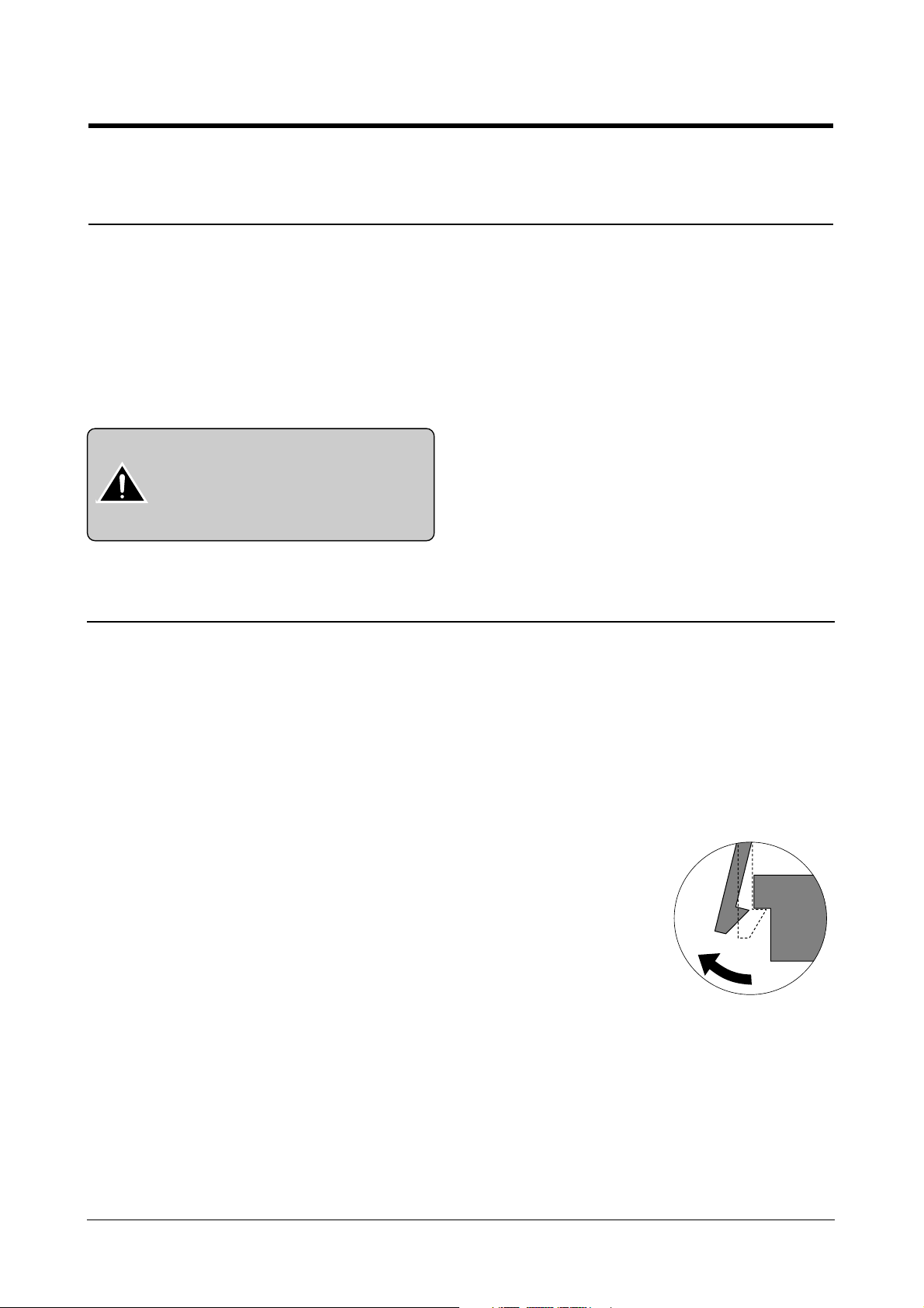
Releasing Plastic Latches
Many of parts are held in
place with plastic latches.
The latches break easily :
release them carefully.
To remove such parts, press
the hook end of the latch
away from the part to which
it is latched.

Certain semiconductor devices can be easily damaged by
static electricity. Such components are commonly called
“Electrostatically Sensitive (ES) Devices”, or ESDs.
Examples of typical ESDs are: integrated circuits, some field
effect transistors, and semiconductor “chip” components.
The techniques outlined below should be followed to help
reduce the incidence of component damage caused by static electricity.
1. Immediately before handling a semiconductor component or semiconductor-equipped assembly, drain off any
electrostatic charge on your body by touching a known
earth ground. Alternatively, employ a commercially available wrist strap device, which should be removed for your
personal safety reasons prior to applying power to the unit
under test.
2. After removing an electrical assembly equipped with
ESDs, place the assembly on a conductive surface, such
as aluminum or copper foil, or conductive foam, to prevent electrostatic charge buildup in the vicinity of the
assembly .
3. Use only a grounded tip soldering iron to solder or desolder ESDs.
4. Use only an “anti-static” solder removal device. Some solder removal devices not classified as “anti-static” can
generate electrical charges sufficient to damage ESDs.
5. Do not use Freon-propelled chemicals. When sprayed,
these can generate electrical charges sufficient to damage ESDs.
6. Do not remove a replacement ESD from its protective
packaging until immediately before installing it. Most
replacement ESDs are packaged with all leads shorted
together by conductive foam, aluminum foil, or a comparable conductive material.
7. Immediately before removing the protective shorting
material from the leads of a replacement ESD, touch the
protective material to the chassis or circuit assembly into
which the device will be installed.
8. Maintain continuous electrical contact between the ESD
and the assembly into which it will be installed, until completely plugged or soldered into the circuit.
9. Minimize bodily motions when handling unpackaged
replacement ESDs. Normal motions, such as the brushing together of clothing fabric and lifting one’s foot from a
carpeted floor, can generate static electricity sufficient to
damage an ESD.
1-3 ESD Precautions
Precautions
1-2
Samsung Electronics
CAUTION:
Be sure no power is applied to the chassis or circuit, and observe all other safety precautions.

Samsung Electronics
2-1
2. Specifications
2-1 Printer Engine
Technology Color Thermal Inkjet
Engine Type 2-Pen (K and CMY)
Operating System Windows 95/98/2000/Me/XP
Interface USB (without HUB Mode), IEEE1284(ECP Support)
Emulation HBP(GDI)
Print Speed
(2)
Mono 14 ppm Draft
Color 7 ppm Draft
Print Resolution (H x V) True 600 X 1200dpi, 2400(H) x 1200(V) dpi (Addressable)
Maximum Paper Size A4, Letter, Legal
Effective Printing Width 8.0'' (203 ± 1mm)
Feeding Method Automatic 100 Sheets (Maximum stacking height : 9mm)
Manual Tray No
Output Tray Capacity Maximum 30 sheets
Maximum Cable Length USB Cable, Max 6ft
(3)
Note:
(2) Speed claims based on the test files: spdtst.sam(mono), spdtstc2.sam(color)/Letter size
(3) Non-standard cable can cause misoperations.
2-2 Scanner
Operation System Windows 98/Me/2000/XP
Interface USB (without HUB Mode) , IEEE1284(ECP Support)
Compatibility TWAIN
Device Platen Color CCD
Scan Width Max.: 8.5” (216 mm), Effective: 8.2” (210 mm)
Color Depth Internal 36 bit, External 24 bit
Optical Resolution (H x V) 600 x 600 dpi, 1200dpi class
Interpolation Resolution Max. 4800 dpi
Pre-scan Mode Yes, 75 dpi
Scan Speed about 2'30 sec/A4 True Color
(Pentium II 300M, 64MB Memory, 300dpi)

Samsung Electronics
Specifications
2-2
2-3 Copier
Scanner Type Flat-bed with ADF (Automatic Document Feeder)
Maximum Original Size A4/Letter
Maximum Paper Size A4/Letter/Legal
Maximum Scan Width 216 mm
Copy Mode Color / Black and White
Copy Quality Draft, Normal, Best
Paper Type Selection Plain, Glossy, Transparency
Mono Copy Speed
(1)
Draft: 10cpm
Color Copy Speed
(1)
Draft: 5cpm
Effective Print-edge Margin Top: 2±1mm, Bottom: 4±1mm, Each Side: 3.5mm(A4)
Multi copy 1~99 pages (Memory Multi copy)
Zoom Rate 25 % ~ 400 % (1 % Step)
Contrast Control 3 Steps
Ink Saver Mode Dot Elimination. Max. 50%
Auto Sensing Check Paper Jam , Low Ink
FCOT Cold/Warm About 40 sec for Default Mode Copy
Note:
(1) Speed claims based on the test chart : Printed spdtst.sam(mono), Printed spdtstc2.sam(color)/Letter size
2-4 Facsimile
Machine type Desk Top
Applicable line G3 PSTN (Public Switched Telephone Network)
Compatibility ITU Group3
Data coding MH/MR/MMR/JPEG/Error Correction Mode
FAX Mode Standard , Fine , Super Fine , Color
Modem speed 33,600 bps
Transmission speed Approx. 3 sec. CCITT Chart
Effective scanning width 8.2 inches(208 mm)
Memory 4 MByte
Automatic document feeder 30 pages(75g/m2)
LCD 16 characters X 2 lines
Battety B/U Max 30 Min
Samsung Electronics
Specifications
2-3
2-6 Power Supply
Rated AC Input Voltage 110 ~ 240 VAC (Universal)
Rated Input Frequency 50 ~ 60 Hz
Minimum/Maximum AC Input 90 VAC/265 VAC
Maximum Input Current 0.5 A
DC Channels
(4)
(2 Channels) +3.3V +
5%, +30V +
10%
2-7 Dimension
Machine Size (W x D x H) 18.7 X 16.9 X 9.9 inch (476 X 429X X252 mm)
Machine Weight About 9.5 Kg (Machine itself)
Note:
(4) No load condition.
2-8 Environmental Condition
Absolute Storage Temperature
(5)
-20oC ~ 55oC
Absolute Storage Humidity
(5)
15% RH ~ 85% RH
Recommended Temperature 16oC ~ 32oC
Operating Condition Humidity 40% RH ~ 70% RH
Note:
(5) Packing Condition
2-5 Ink Cartridge
Babbage mono Birch color
Print Head 208 nozzles 192 nozzles
Ink type Pigment Dye
Ink Color Black Color
Ink Yield Standard about 600 sh. (5% Pattern, A4) about 275 sh. (15% Pattern, A4)
High Yield about 1,100 sh.(5% Pattern, A4) about 625 sh. (15% Pattern, A4)

When you disassemble and reassemble components, you
must use extreme caution.
The close proximity of cables to moving parts makes proper routing a must. If components are removed or replaced,
any cables disturbed by the procedure must be replaced as
close as possible to their original positions.
Before removing any component from the machine, note
the cable routing that will be affected.
Whenever servicing the machine, you must perform as
follows:
1. Check to verify that documents are not stored in memory.
2. Unplug the power cord.
3. Use a flat and clean surface.
4. Replace only with authorized components.
5. Do not force to remove or planten plastic-material components.
6. Make sure all components are in their proper position.
3-1
Samsung Electronics
3. Disassembly and Reassembly
3-1 General Precautions on Disassembly
Disassembly and Reassembly
3-2
Samsung Electronics
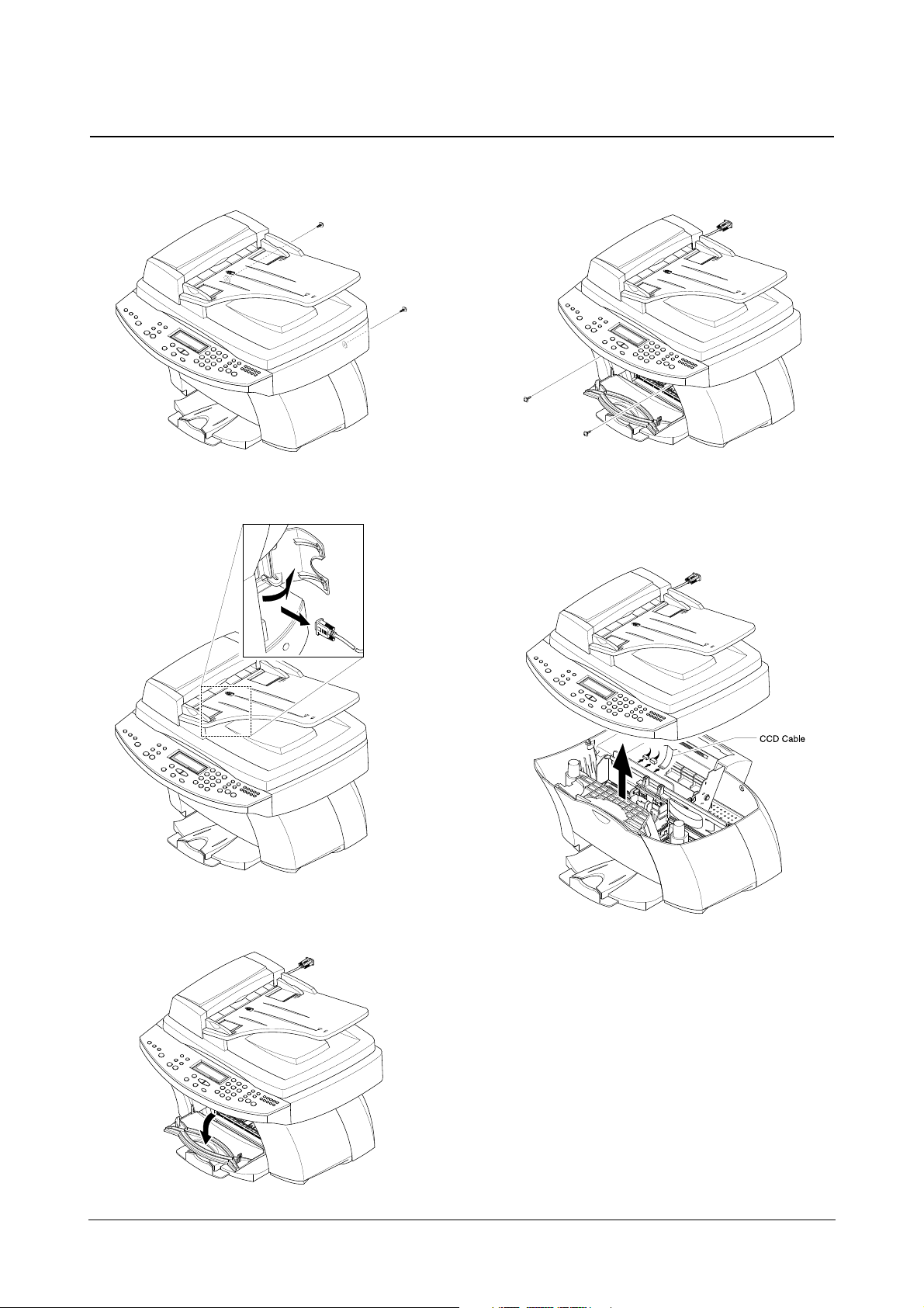
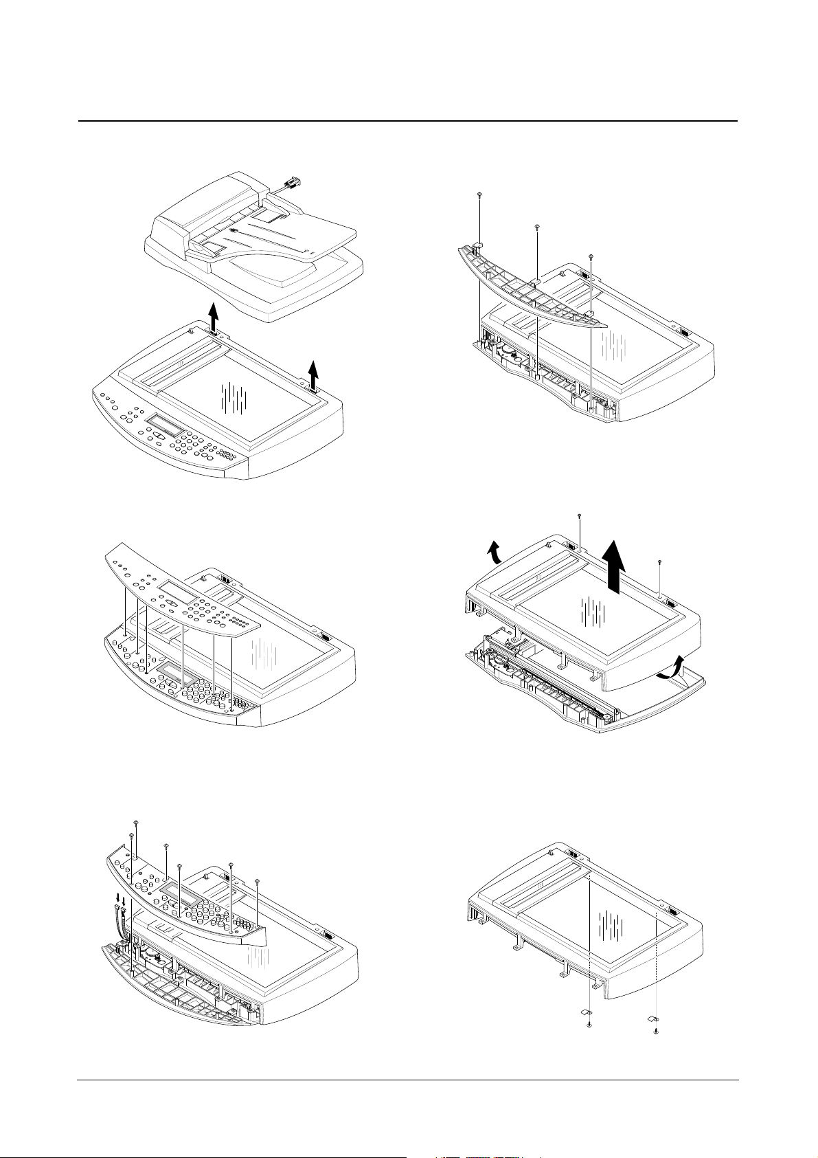
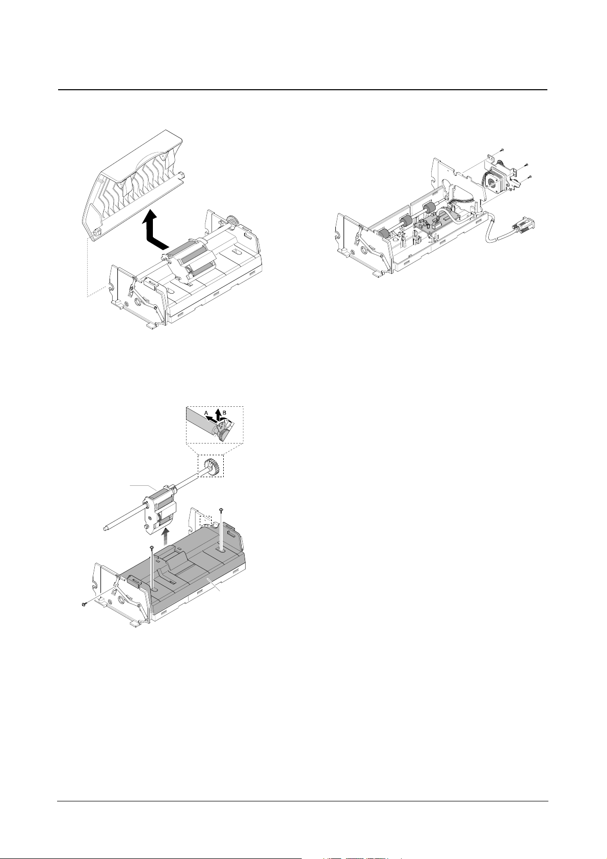
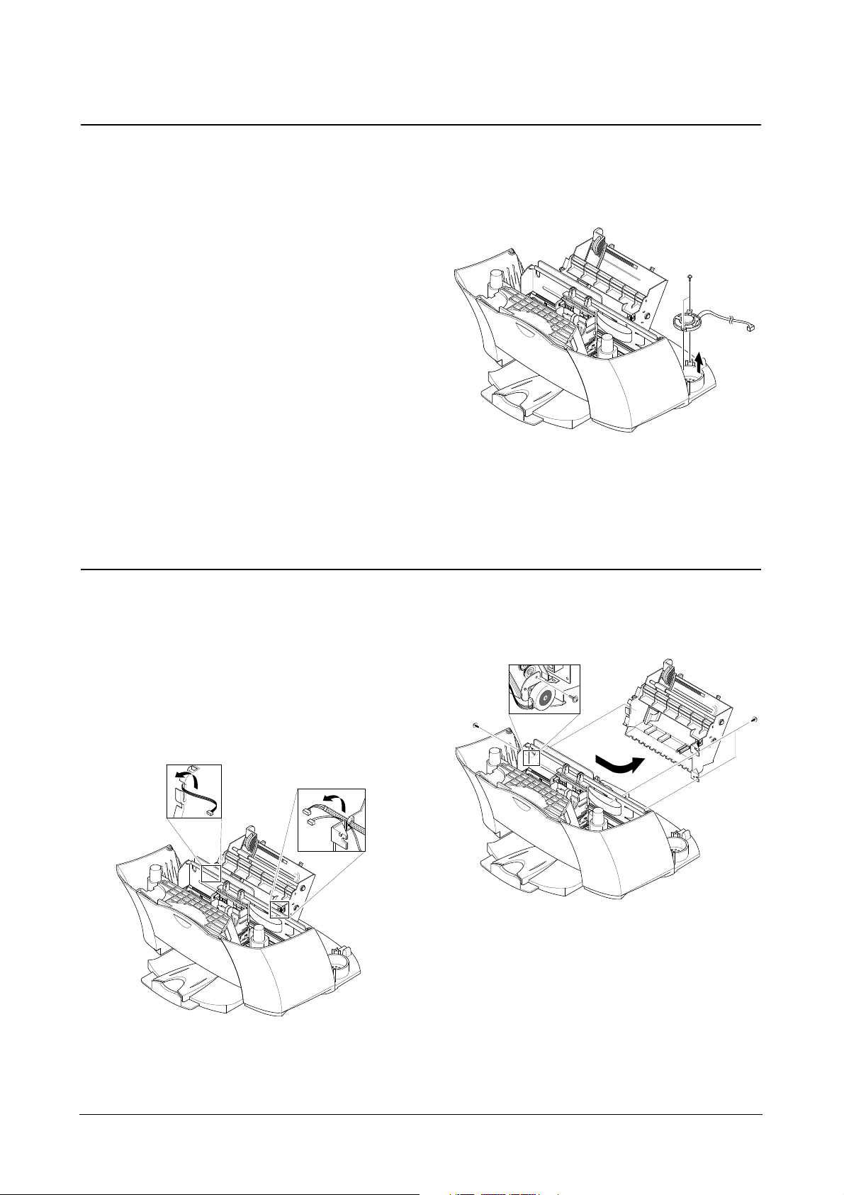
3-2 Scanner Ass’y
1. Remove two screws securing the Rear Cover.
2. Open the Side Door and remove the ADFConnector,
as shown below.
3. Open the Front Door from the Main Cover.
4. Remove two screws securing the Main Cover.
5. Pull the Scanner Ass’y upward then, unplug the two
connectors and CCD Cable.
♦ You should connect or remove the CCD Cable vertically to
avoid the CCD Cable pin damage.
Disassembly and Reassembly
3-3
Samsung Electronics
6. Pull the ADF unit(platen Cover) upward and remove it.
7. Pull the OPE Cover upward and remove it.
8. Remove six screws securing the OPE Upper and
unplug the two connectors from the OPE panel.
9. Remove three screws securing the OPE lower and
remove it.
10. Remove two screws and unlatch the scan lawer
securing the scan upper and remove it.
11. Remove the two screws securing the scan upper
and take out the glass holder.
Disassembly and Reassembly
3-4
Samsung Electronics
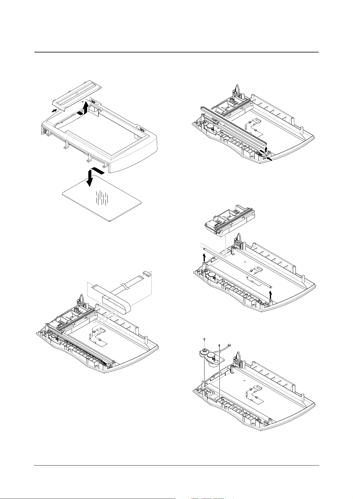
12. Unlatch the Scan Dummy and take out the Glass
from the Scan Upper.
13. Remove the CCD Cable.
14. Push the Belt Holder and take out the Belt, as shown
below.
15. Pull up the CCD Shaft and take out the Scanner
Module.
16. Remove two screws and take out the Motor Bracket.
Disassembly and Reassembly
3-5
Samsung Electronics
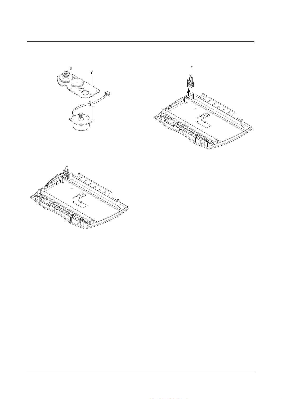
17. Remove two screws securing the Scan Motor and
remove it.
18. Unplug the one connector from the open Sensor
Ass’y.
19. Remove the one screw securing the open Sensor
Ass’y and remove it.
Disassembly and Reassembly
3-6
Samsung Electronics
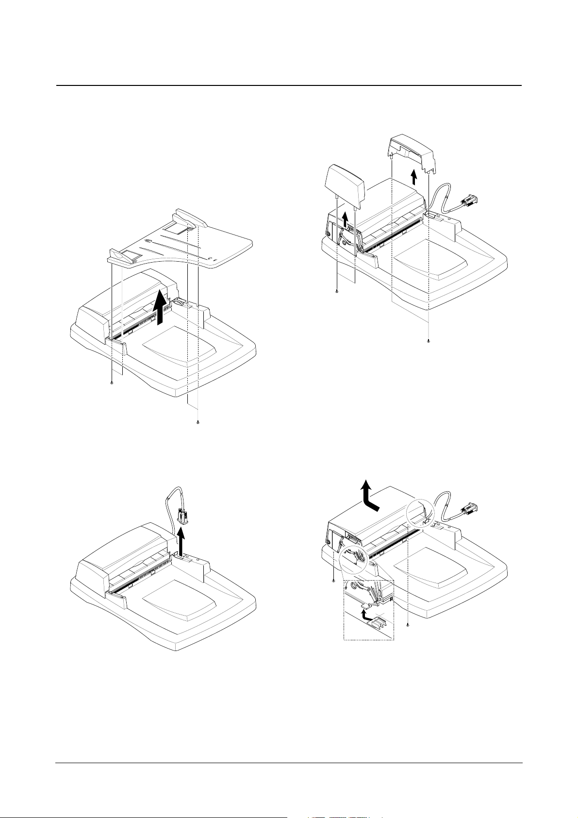
3-3 ADF Motor Ass’y
1. Before you remove the ADF Motor Ass’y, you should
remove:
• Scanner Ass’y (see page 3-2)
2. Remove the four screws securing the TX Stacker and
remove it.
3. Take out the ADF connector.
4. Remove the four screws securing the Side Cover(L,R)
and remove it.
5. Remove the two screws securing the ADF Unit and
remove it.
Disassembly and Reassembly
3-7
Samsung Electronics
6. Take out the Open Cover.
7. Take out the Pick-Up Ass’y & ADF Upper.
8. Remove the three screws and the one Connector
securing the ADF unit and remove it.
Pick-up Ass’y
ADF Upper
Disassembly and Reassembly
3-8
Samsung Electronics
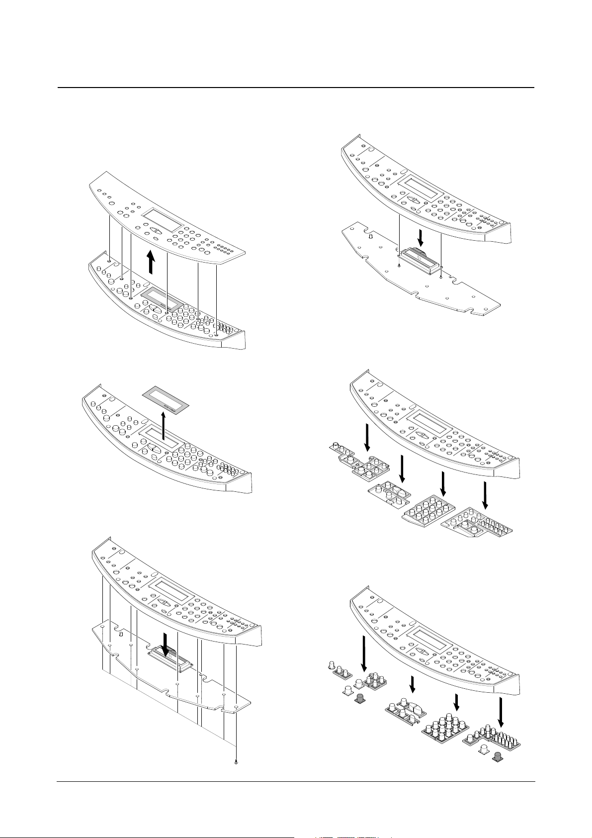
3-4 OPE Unit
1. Before you remove the OPE Unit, you should remove:
• Scanner Ass’y (see page 3-2)
2. Pull the OPE Cover upward and remove it.
3. Take out the LCD window from the OPE Upper.
4. Remove nine screws securing the OPE Upper to the
OPE panel.
5. Remove two screws securing the OPE Upper to the
LCD Board.
6. Remove the contact rubber from the OPE Upper.
7. Remove the Key pad from the OPE Upper.
Disassembly and Reassembly
3-9
Samsung Electronics
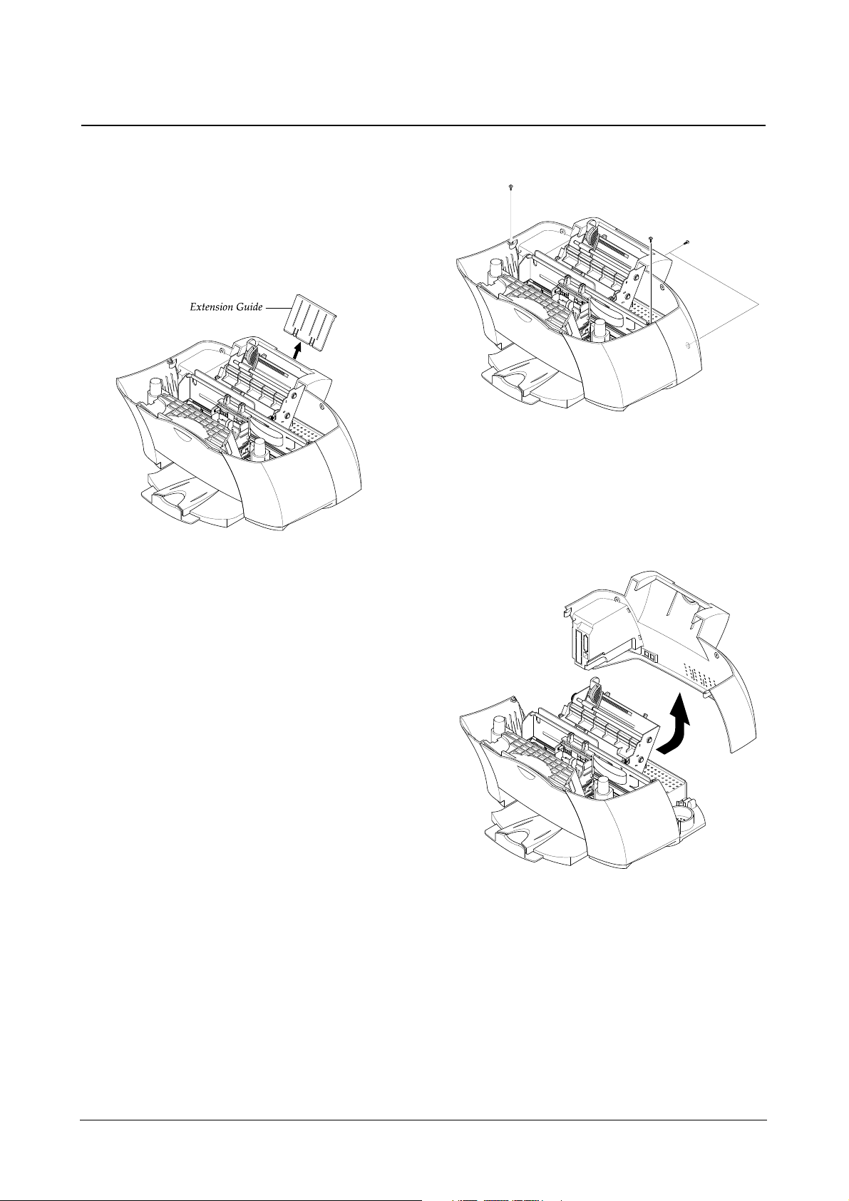
3-5 Rear Cover
1. Before you remove the rear Cover, you should
remove:
• Scanner Ass’y (see page 3-2)
2. Pull the extension guide upward and remove it.
3. Remove four screws securing the rear cover.
4. Remove the rear cover, as shown below.
Disassembly and Reassembly
3-10
Samsung Electronics
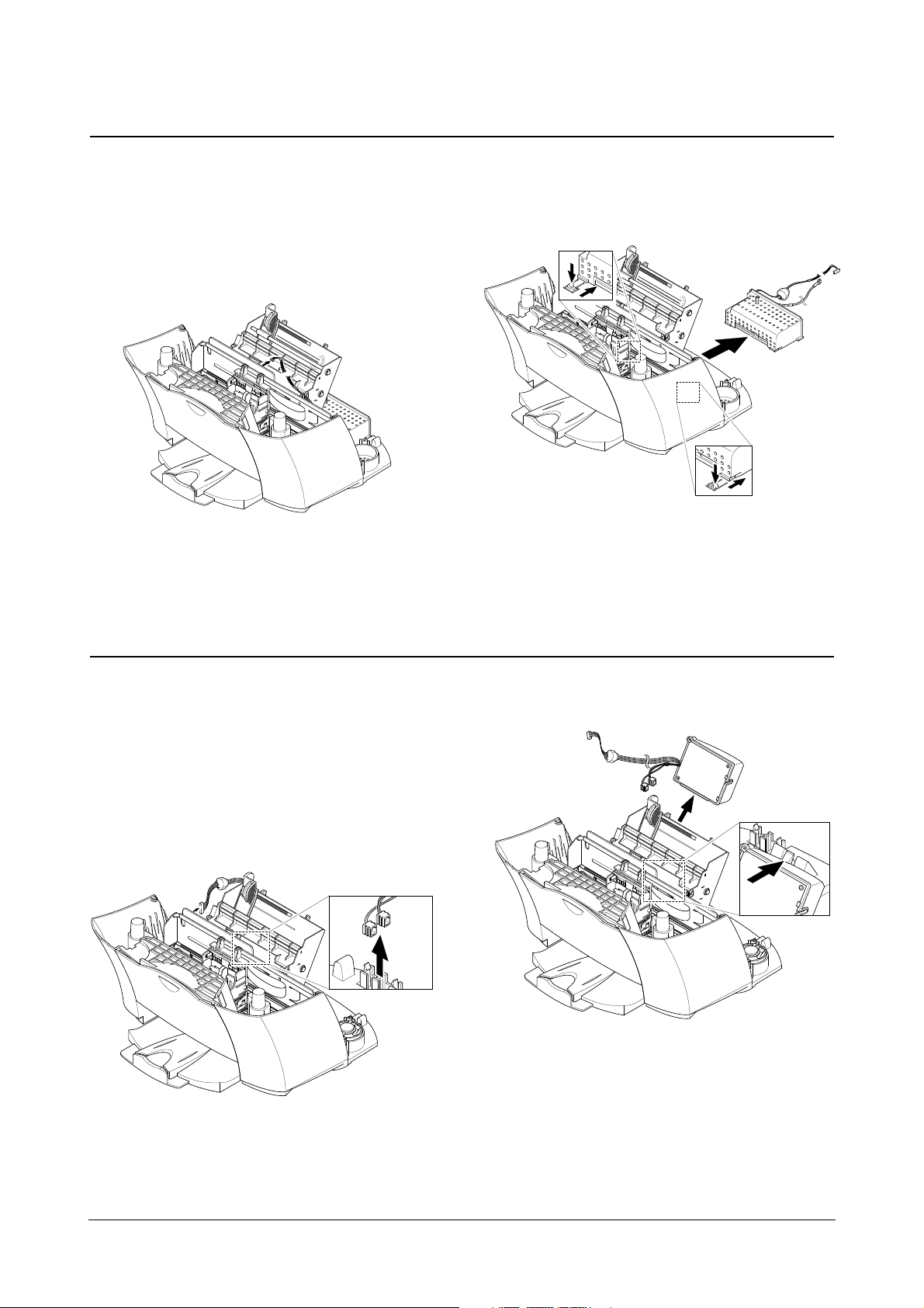
3-6 SMPS
1. Before you remove the SMPS, you should remove:
• Scanner Ass’y (see page 3-2)
• Rear Cover (see page 3-9)
2. Unplug the one connector from the main PBA.
3. Pushing down the Hooks on both ends, pullout the
SMPS.
3-7 LIU Board
1. Before you remove the LIU Board, you should
remove:
• Scanner Ass’y (see page 3-2)
• Rear Cover (see page 3-9)
2. Unplug the one connector and modular, as shown
below.
3. Pull up the Hook on both end, take out the LIU Board.
Disassembly and Reassembly
3-11
Samsung Electronics
3-8 Speaker Ass’y
1. Before you remove the speaker Ass’y, you should
remove:
• Scanner Ass’y (see page 3-2)
• Rear Cover (see page 3-9)
2. Remove the two screws securing the speaker Ass’y
and remove it.
3-9 ASF Feeder
1. Before you remove the asf feeder, you should
remove:
• Scanner Ass’y (see page 3-2)
• Rear Cover (see page 3-9)
• SMPS (see page 3-10)
2. Make sure the harness is released from the Hooks,
as shown below.
3. Remove three screws securing the ASF feeder to
the Main Cover.
Take out the ASF feeder.
Disassembly and Reassembly
3-12
Samsung Electronics
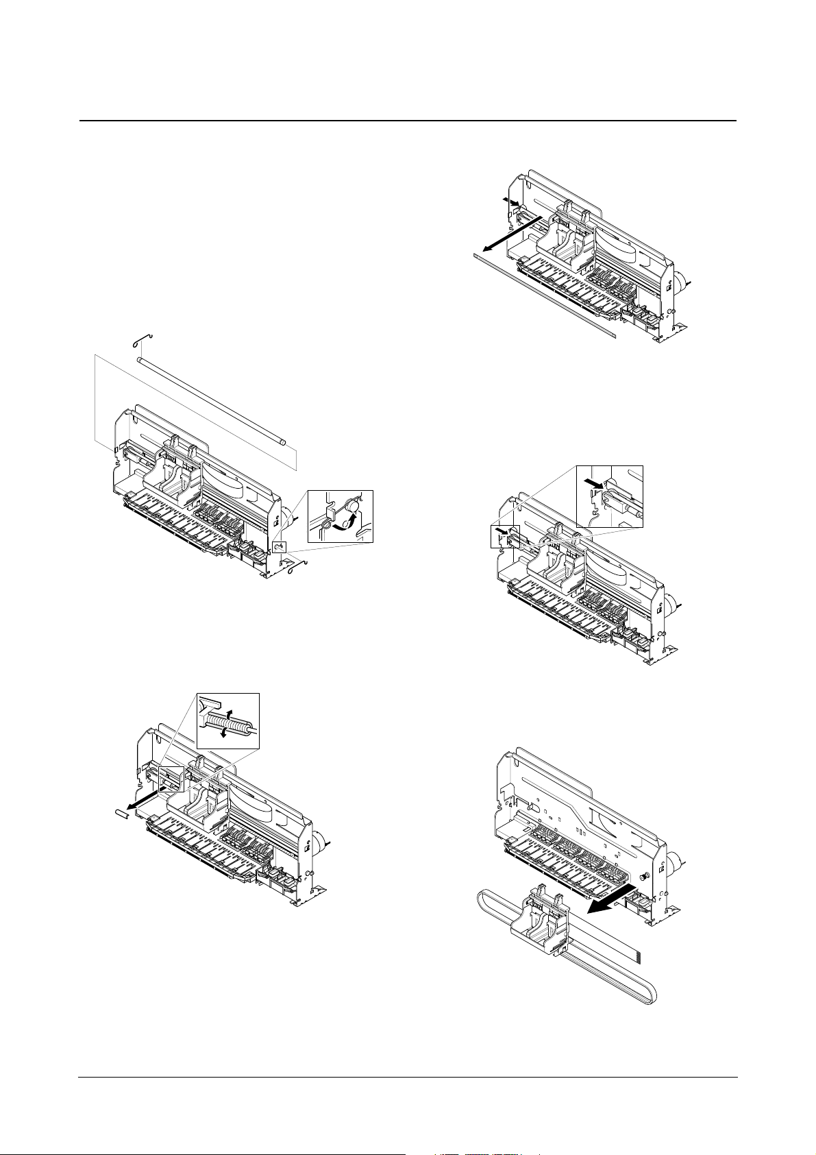
3-10 Cartridge Ass’y
1. Before you remove the cartridge Ass’y you should
remove:
• Scanner Ass’y (see page 3-2)
• Rear Cover (see page 3-9)
• Engine Ass’y
• ASF Feeder (see page 3-11)
2. Rotate to remove both Springs securing the carrier
shaft. Then take out the carrier shaft.
3. Remove the C-cab.
4. Take out the emcoder strip, as shown below.
5. Push the holder pulley to the right and take out the
belt.
6. Take out the cartridge carrier from the Main Frame.
Disassembly and Reassembly
3-13
Samsung Electronics
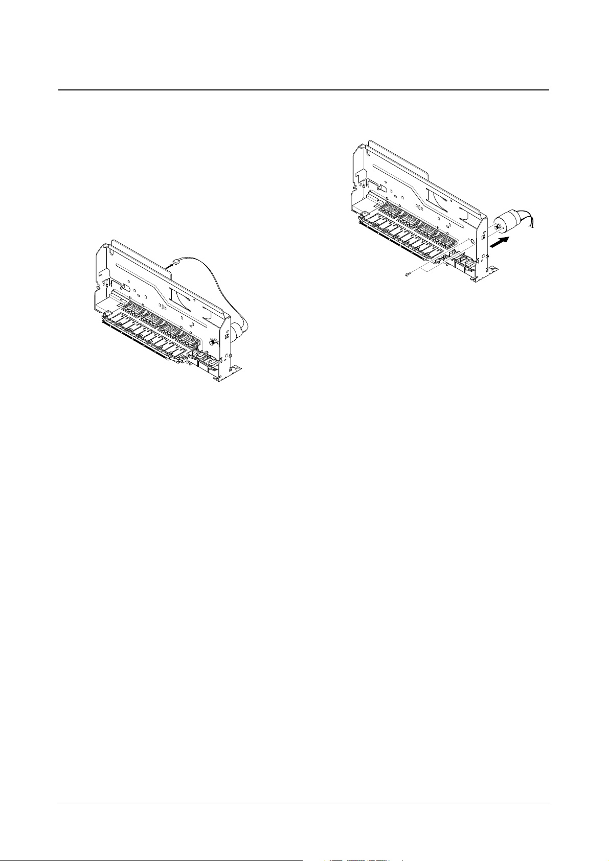
3-11 Carrier Motor
1. Before you remove the carrier motor, you should
remove:
• Scanner Ass’y (see page 3-2)
• Rear Cover (see page 3-9)
• Engine Ass’y
• ASF Feeder (see page 3-11)
• Cartridge Ass’y (see page 3-12)
2. Unplug the one connector from the main PBA.
3. Remove two screws securing the carrier motor
and take out the motor from the Main Frame.
 Loading...