

Samsung SCX 1000 Service Manual
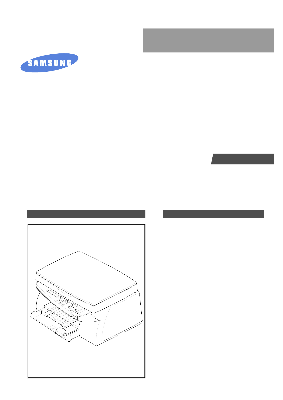
SERVICE
Mult-function Printer
SCX-1000I
SCX-1000SI
Manual
Mult-function Printer
CONTENTS
1. Precautions
2. Specifications
3. Disassembly and Reassembly
4. Maintenance & T roubleshooting
5. Exploded Views and Parts List
6. Electrical Parts List
7. Block Diagrams
8. PCB Diagrams
9. Schematic Diagrams

ELECTRONICS
© Samsung Electronics Co.,Ltd. August 2000
Printed in Korea.
VERSION NO. : 1.00 P/N.: JB-0006A

1. Precautions
Follow these safety, ESD, and servicing precautions to prevent personal injury and equipment damage.
1-1 Safety Precautions
1. Be sure that all built-in protective devices are in
place. Restore any missing protective shields.
2. Make sure there are no cabinet openings through
which people- particularly children- might insert
fingers or objects and contact dangerous voltages.
3. When re-installing chassis and assemblies, be
sure to restore all protective devices, including
control knobs and compartment covers.
4. Design Alteration Warning:
Never alter or add to the mechanical or electrical
design of this equipment, such as auxiliary
connectors, etc. Such alterations and
modifications will void the manufacturer’s
warranty.
5. Components, parts, and wiring that appear to
have overheated or are otherwise damaged
should be replaced with parts which meet the
original specifications. Always determine the
cause of damage or overheating, and correct any
potential hazards.
6. Observe the original lead dress, especially near
sharp edges, AC, and high voltage power
supplies. Always inspect for pinched, out-ofplace, or frayed wiring. Do not change the
spacing between components and the printed
circuit board.
7. Product Safety Notice:
Some electrical and mechanical parts have special
safety-related characteristics which might not be
obvious from visual inspection. These safety
features and the protection they provide could be
lost if a replacement component differs from the
original. This holds true, even though the
replacement may be rated for higher voltage,
wattage, etc.
Components critical for safety are indicated in
the parts list with symbols . Use only
replacement components that have the same
ratings, especially for flame resistance and
dielectric specifications. A replacement part that
does not have the same safety characteristics as
the original may create shock, fire, or other safety
hazards.
Samsung Electronics 1-1

1-2 Samsung Electronics
Precautions
1-2 ESD Precautions
Certain semiconductor devices can be easily
damaged by static electricity. Such components are
commonly called “Electrostatically Sensitive (ES)
Devices”, or ESDs. Examples of typical ESDs are:
integrated circuits, some field effect transistors, and
semiconductor “chip” components.
The techniques outlined below should be followed
to help reduce the incidence of component damage
caused by static electricity.
CAUTION: Be sure no power is applied to the
chassis or circuit, and observe all other safety
precautions.
1. Immediately before handling a semiconductor
component or semiconductor-equipped assembly,
drain off any electrostatic charge on your body
by touching a known earth ground. Alternatively,
employ a commercially available wrist strap
device, which should be removed for your personal
safety reasons prior to applying power to the unit
under test.
2. After removing an electrical assembly equipped
with ESDs, place the assembly on a conductive
surface, such as aluminum or copper foil, or
conductive foam, to prevent electrostatic charge
buildup in the vicinity of the assembly.
3. Use only a grounded tip soldering iron to solder
or desolder ESDs.
4. Use only an “anti-static” solder removal device.
Some solder removal devices not classified as
“anti-static” can generate electrical charges
sufficient to damage ESDs.
5. Do not use Freon-propelled chemicals. When
sprayed, these can generate electrical charges
sufficient to damage ESDs.
6. Do not remove a replacement ESD from its
protective packaging until immediately before
installing it. Most replacement ESDs are
packaged with all leads shorted together by
conductive foam, aluminum foil, or a comparable
conductive material.
7. Immediately before removing the protective
shorting material from the leads of a replacement
ESD, touch the protective material to the chassis
or circuit assembly into which the device will be
installed.
8. Maintain continuous electrical contact between
the ESD and the assembly into which it will be
installed, until completely plugged or soldered
into the circuit.
9. Minimize bodily motions when handling
unpackaged replacement ESDs. Normal motions,
such as the brushing together of clothing fabric
and lifting one’s foot from a carpeted floor, can
generate static electricity sufficient to damage an
ESD.
2. Specification
2-1 Copier
Scanner Type Flat-bed without ADF (Automatic Document Feeder)
Maximum Original Size A4/Letter
Maximum Paper Size A4/Letter/Legal
Maximum Scan Width 216 mm
Optical Resolution (HxV) 300 x 600 dpi
Copy Quality Fast, Normal, Best
Mono Copy Speed Maximum: 4cpm.
Color Copy Speed Maximum: 1.5cpm.
Maximum Print-edge Margin Top: 3.4mm, Bottom: 19.5mm, Each Side: 6.5mm
Multicopy 99 pages
Zoom Rate 25 % ~ 400 % (1 % Step)
Contrast Control 3 Steps
2-1Samsung Electronics
2-2 Printer
Technology Color Thermal Inkjet
Engine Type 2-Pen (K and CMY)
Operating System Windows 95/98/NT
Interface IEEE 1284 (ECP Support), USB (without HUB Mode)
Emulation HBP
Print Speed
(2)
Mono 9ppm Draft / 7ppm Normal
Color 4.5ppm Draft / 2ppm Normal
Print Resolution (H x V) Draft 300 x 600 dpi
Normal 600 x 600 dpi
Best 1200 x 1200 dpi (Addressable)
Maximum Paper Size A4, Letter, Legal
Effective Printing Width 8.0” (203 ± 1mm)
Paper Feeding Capacity Maximum150 Sheets
Output Tray Capacity Maximum 50 sheets
Maximum Cable Length 6 ft(1.8m) of standarol IEEE 1284
(3)
Note:
(2) Speed claims based on the test files: spdtst.sam(mono), spdtstc2.sam(color)/Letter size
(3) Non-standard cable can cause misoperations.

2-2 Samsung Electronics
Specification
2-3 Scanner
Operation System Windows 95/98/NT
Interface IEEE 1284 (ECP Support), USB (without HUB Mode)
Compatibility TWAIN
Device Platen Color CIS (Contact Image Sensor)
Scan Width Max.: 8.5” (216 mm), Effective: 8.2” (210 mm)
Color Depth 30 bit
Optical Resolution (H x V) 300 x 600 dpi
Interpolation Resolution Max. 4800 dpi
Pre-scan Mode Yes, 75 dpi
2-4 Ink-head
Mono Cartridge Color Cartridge
Head Babbage 208 nozzles Birch 192 nozzles
Ink type Pigment Dye
Ink Color Black Color (CMY)
Ink Yield High yield : 1075 pages 200 pages
2-5 Power Supply
Rated AC Input Voltage 110 ~ 240 VAC (Universal)
Rated Input Frequency 50 ~ 60 Hz
Minimum/Maximum AC Input 90 VAC/265 VAC
Maximum Input Current 3A
DC Channels
(4)
+5V +5%, +12V +2%, +30V +5%

Samsung Electronics 2-3
Specification
2-6 Dimension
Machine Size (W x D x H) 445 x 369x 258mm
Machine Weight About 7.8 Kg (Machine itself)
2-7 Packaging
Power Cord 1EA
IEEE 1284 Cable 1EA
USB Cable No
CD-ROM 2EA
Ink Cartridge Mono 1EA, Color 1EA
Manual 2vol.
2-8 Environmental Condition
Absolute Storage Temperature
(5)
-25oC ~ 60oC
Absolute Storage Humidity
(5)
10% RH ~ 90% RH
Recommended Temperature 16oC ~ 32oC
Operating Condition Humidity 40% RH ~ 70% RH
2-9 Machine Life
Product Life in Time 3 Years
Life Time in Pages 20,000 Printing Pages
Maximum Monthly Duty Cycle 1,200 Printing Pages except Ink-head
Note:
(5) Packing Condition

2-4 Samsung Electronics
Specification
MEMO

3. Disassembly and Reassembly
3-1 General Precautions on Disassembly
When you disassemble and reassemble components, you must use extreme caution. The close proximity of
cables to moving parts makes proper routing a must. If components are removed or replaced, any cables
disturbed by the procedure must be replaced as close as possible to their original positions. Before removing
any component from the machine, note the cable routing that will be affected.
Whenever servicing the machine, you must perform as follows:
1. Check to verify that documents are not stored in memory.
2. Unplug the power cord.
3. Use a flat and clean surface.
4. Replace only with authorized components.
5. Do not force to remove or planten plastic-material components.
6. Make sure all components are in their proper position.
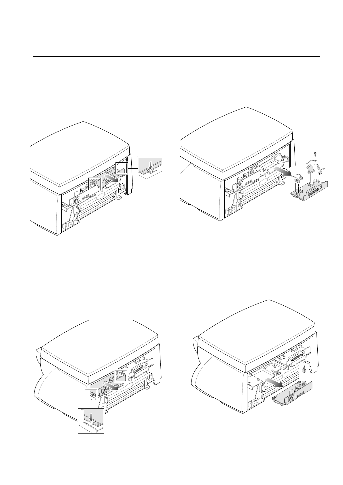
1. Remove the guide outer.
2. Remove two screws securing the rear cover.
Separate the rear cover from the main frame.
Samsung Electronics 3-1
3-2 Rear Cover
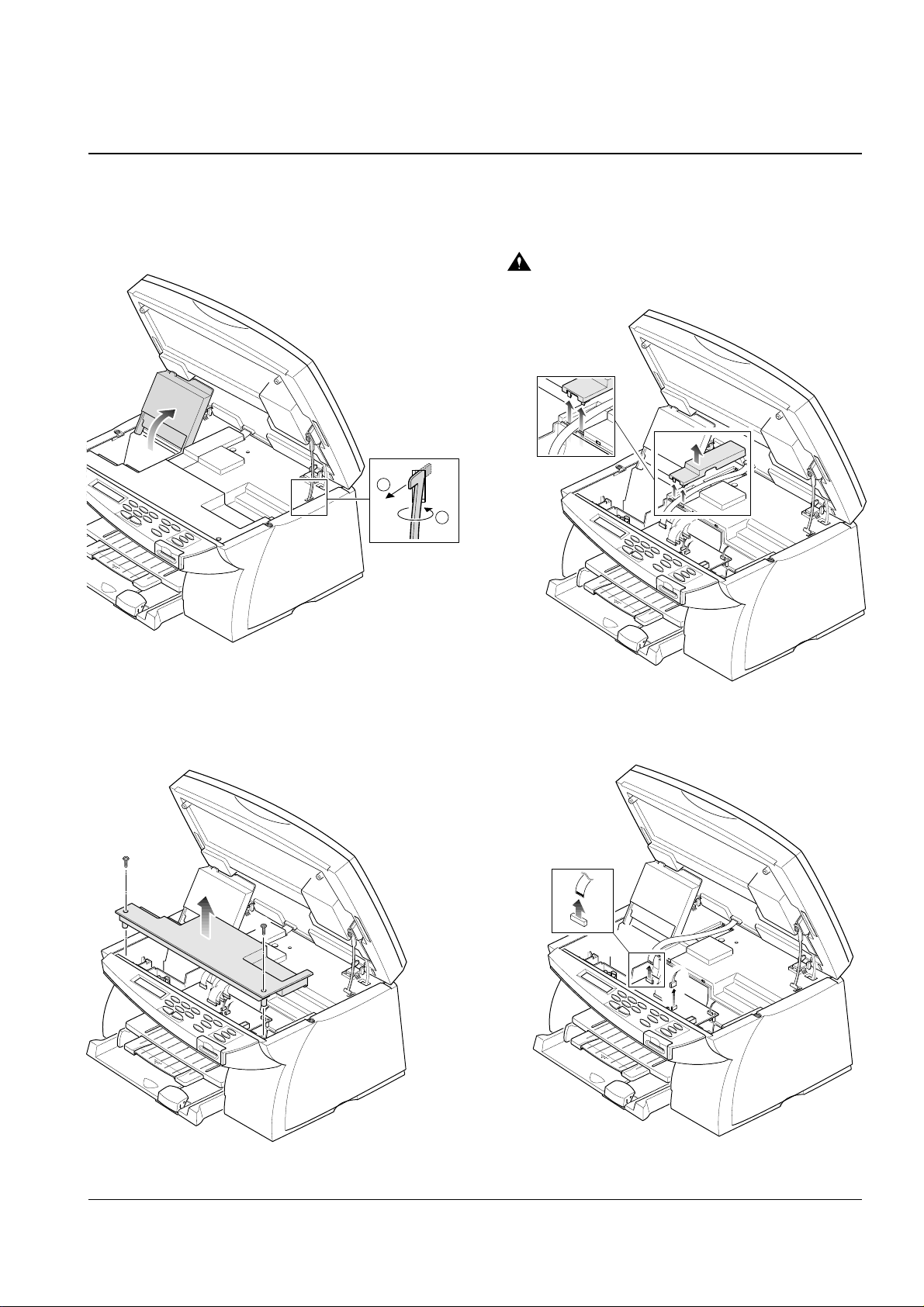
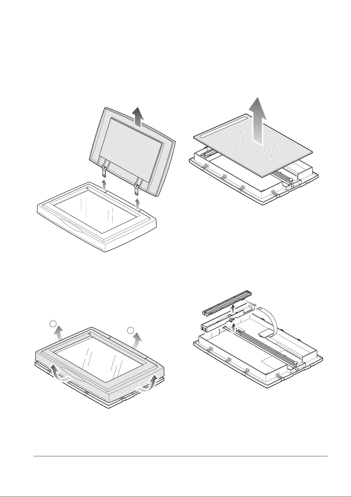
3-3 Scanner Unit Assembly
3-2 Samsung Electronics
Disassembly and Reassembly
1. Raise the scanner support to hold up the scanner
unit and remove the stopper holding the scanner
unit.
2. Remove two screws and take out the PCB cover.
4. Unplug the harness and one connector from
the main PBA.
3. Unlatch the harness cover by pushing on the
bottom of the tabs upward, then remove the
cover.
1
2
Unlatch the cover.
You should connect or remove the FPC cable
vertically to avoid the FPC cable pin damage.
FPC cable
7. Pull the scanner unit backward and remove the
assembly from the main frame.
3-3Samsung Electronics
Disassembly and Reassembly
6. Place the scanner support to its original
position.
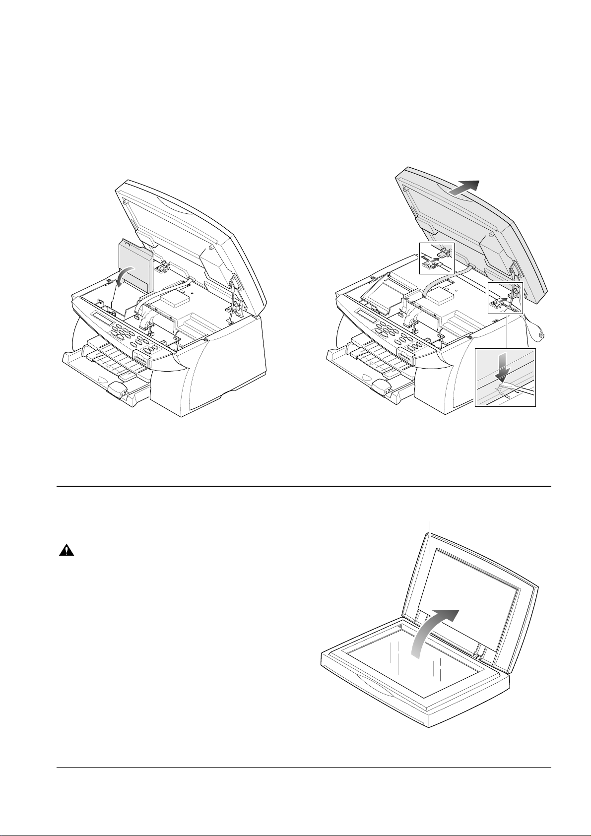
3-4 Scanner
1. Before you disassemble the scanner, you should
remove:
* Scanner unit assembly (See page 3-3)
Before you assemble or disassemble the
scanner, you should take on the wrist strap
device for ESD protection. (See 1-2 ESD
precausions)
2. Lift and open the platen cover.
Planten cover
3-4 Samsung Electronics
Disassembly and Reassembly
4. Unlatch the frame securing the scanning glass
and remove it.
5. Remove the glass from the main frame.
6. Lift the CIS and unplug one connector from the
CIS.
1
2
3. Pull the cover upward and remove it.
3-5Samsung Electronics
Disassembly and Reassembly
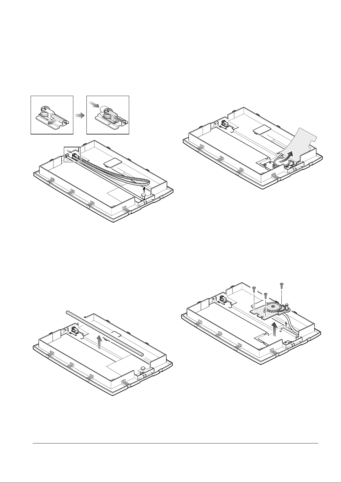
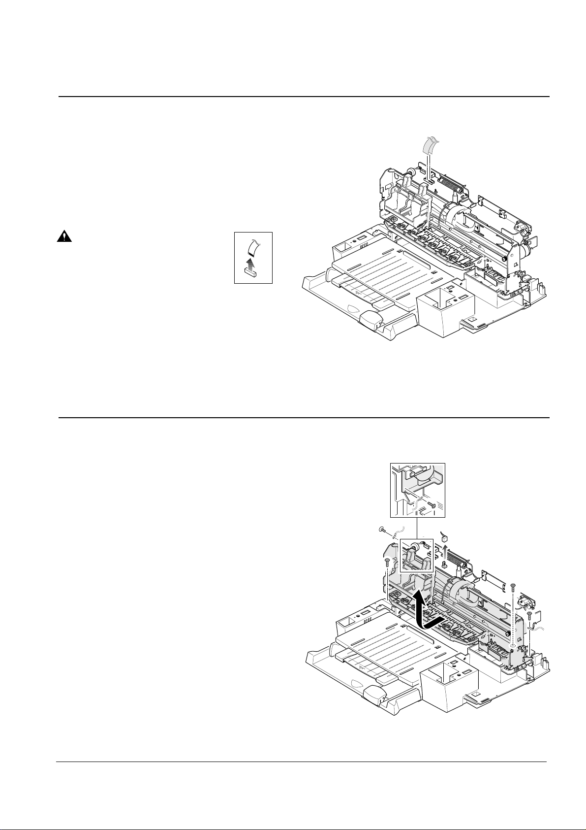
9. Remove the cover of the motor bracket.
10. Remove three screws and take out the motor
bracket.
8. Remove the shaft.
7. Remove C-cap, then push the part marked
with A and remove the belt.
A
3-6 Samsung Electronics
Disassembly and Reassembly
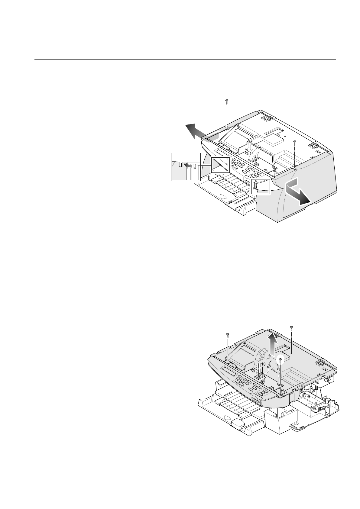
1. Remove two screws securing the PCB cover to the
main frame. Take out the PCB cover.
2. Unplug one connector from the PCB.
3. Unlatch the OPE panel to the direction of the
arrows and take out the cover.
3-5 OPE panel
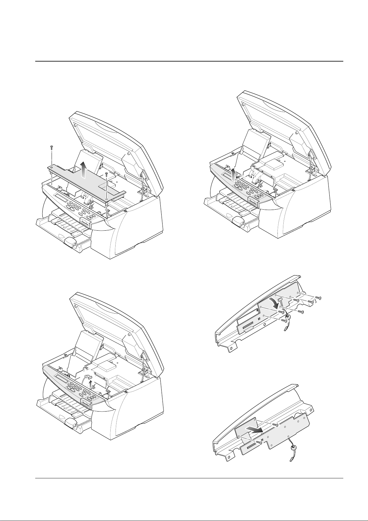
6. Remove two screws and remove the LCD
board with OPE board.
5. Remove six screws, then turn the OPE board
upside down.
3-7Samsung Electronics
Disassembly and Reassembly
3. Remove two screws securing the board and take
the board out.
1. Open the scanner unit.
2. Remove two screws securing the PCB cover.
Take out the cover from the main frame.
3. Remove two screws securing the main PBA to
the main frame and unplug all connectors. Take
out the main PBA.
3-7 Main PBA
You should connect or remove the
FPC cable vertically to avoid the
FPC cable pin damage.
1. Before you disassemble the smart board, you
should remove:
* OPE panel (See page 3-6)
2. Unplug one FPC cable from the PCB.
3-6 Smart board
3-8 Samsung Electronics
Disassembly and Reassembly
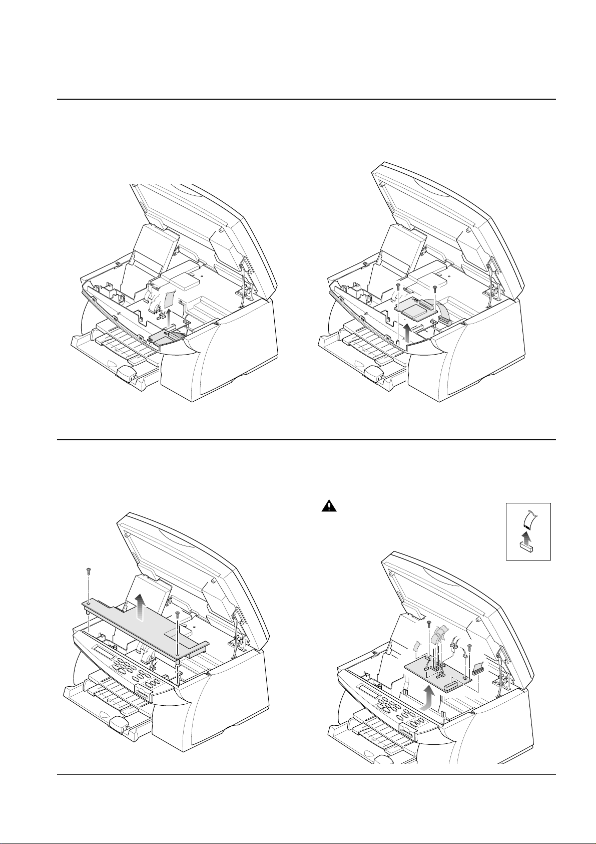
3-8 Drive PBA
1. Before you disassemble the drive PBA, you
should remove:
* Rear cover. (See page 3-1)
2. Unlatch the drive PBA, then pull it toward you.
3. Remove one ground screw and unplug all
connectors, then remove the drive PBA.
Push the locker
to unlatch the
board.
1. Before you disassemble the SMPS, you should
remove:
* Rear cover. (See page 3-1)
2. Unlatch the Drive PBA, then pull it toward you.
3. Remove one connector, then remove the SMPS.
3-9 SMPS
Push the locker to unlatch
the board.
3-9Samsung Electronics
Disassembly and Reassembly
1. Before you disassemble the side covers (R/L),
you should remove:
* Rear cover (See page 3-1)
* Scanner unit assembly (See page 3-2)
2. Remove two screws and remove the right and
left side covers.
3-10 Side Covers (R/L)
1. Before you disassemble the middle cover, you
should remove:
* Rear cover (See page 3-1)
* Scanner unit assembly (See page 3-2)
* Side covers (R/L) (See above)
2. Remove three screws and remove all connectors.
Then take out the middle cover.
3-11 Middle Cover
3-10
Disassembly and Reassembly
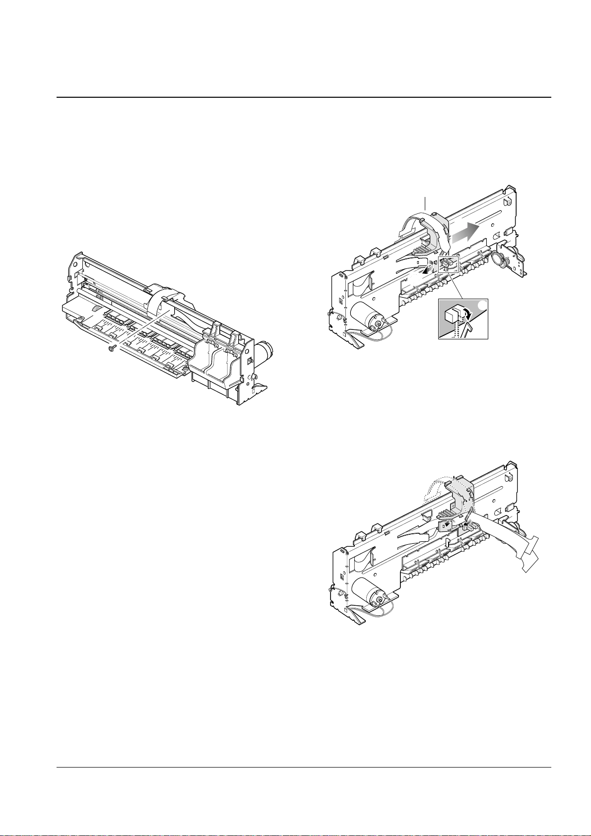
3-13 Engine Unit
3-12 FPC Cable
1. Before you disassemble the engine unit,
you should remove:
* All covers (See page 3-1, 3-9, 3-10)
* Scanner unit assembly (See page 3-2)
2. Remove four screws securing the engine unit, and
unplug one connector from the drive PBA.
3. Take out the engine unit from the ASF frame.
1. Before you disassemble the FPC cable
you should remove:
* All covers (See page 3-1, 3-9, 3-10)
* Scanner unit assembly(see page 3-2)
2. Unplug two FPC cables.
You should connect or remove the
FPC cable vertically to avoid the
FPC cable pin damage.
Samsung Electronics
3-11
Disassembly and Reassembly
1. Before you disassemble the FPC holder assembly
you should remove:
* All covers (See page 3-1, 3-9, 3-10)
* Scanner unit (See page 3-2)
* Engine unit. (See page 3-10)
2. Remove one screw securing the FPC holder
to the main frame.
3. Pull the part ¨ out to unlatch the FPC holder
and pull the sensor actuator ≠ out, then slide
the FPC holder in the direction of Æ.
4. Remove the FPC cable from the main frame.
3-14 FPC Holder Assembly
¨
FPC holder
≠
Æ
Samsung Electronics
3-12 Samsung Electronics
Disassembly and Reassembly
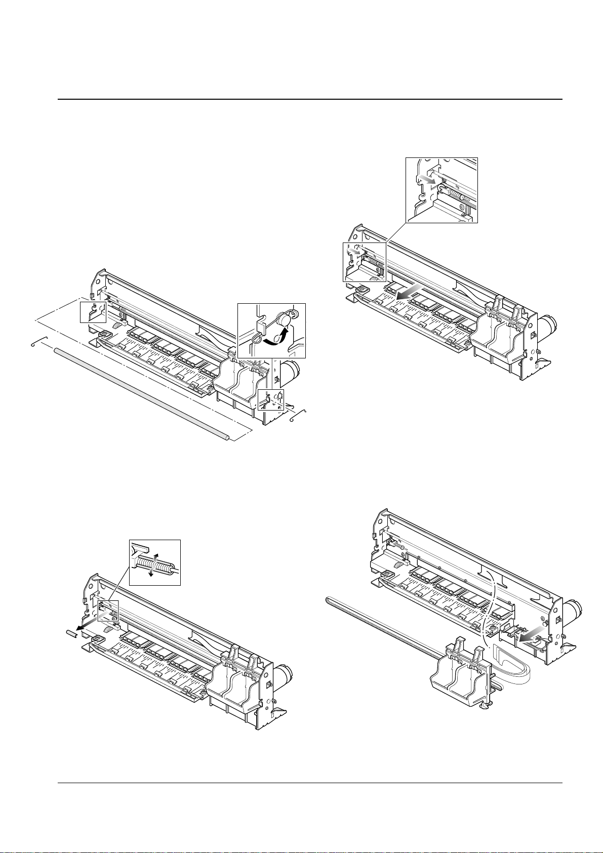
3. Remove the C-cap.
5. Take out the cartridge carrier from the main frame.
1. Before you disassemble the cartridge assembly
you should remove:
* All covers (See page 3-1, 3-9, 3-10)
* Scanner unit assembly (see page 3-2)
* Engine unit (See page 3-10)
* FPC holder assembly (See page 3-11)
2. Rotate to remove both springs securing the
carrier shaft. Then take out the carrier shaft.
4. Push the holder pulley to the right and take
out the belt.
3-15 Cartridge Assembly
3-13
Disassembly and Reassembly
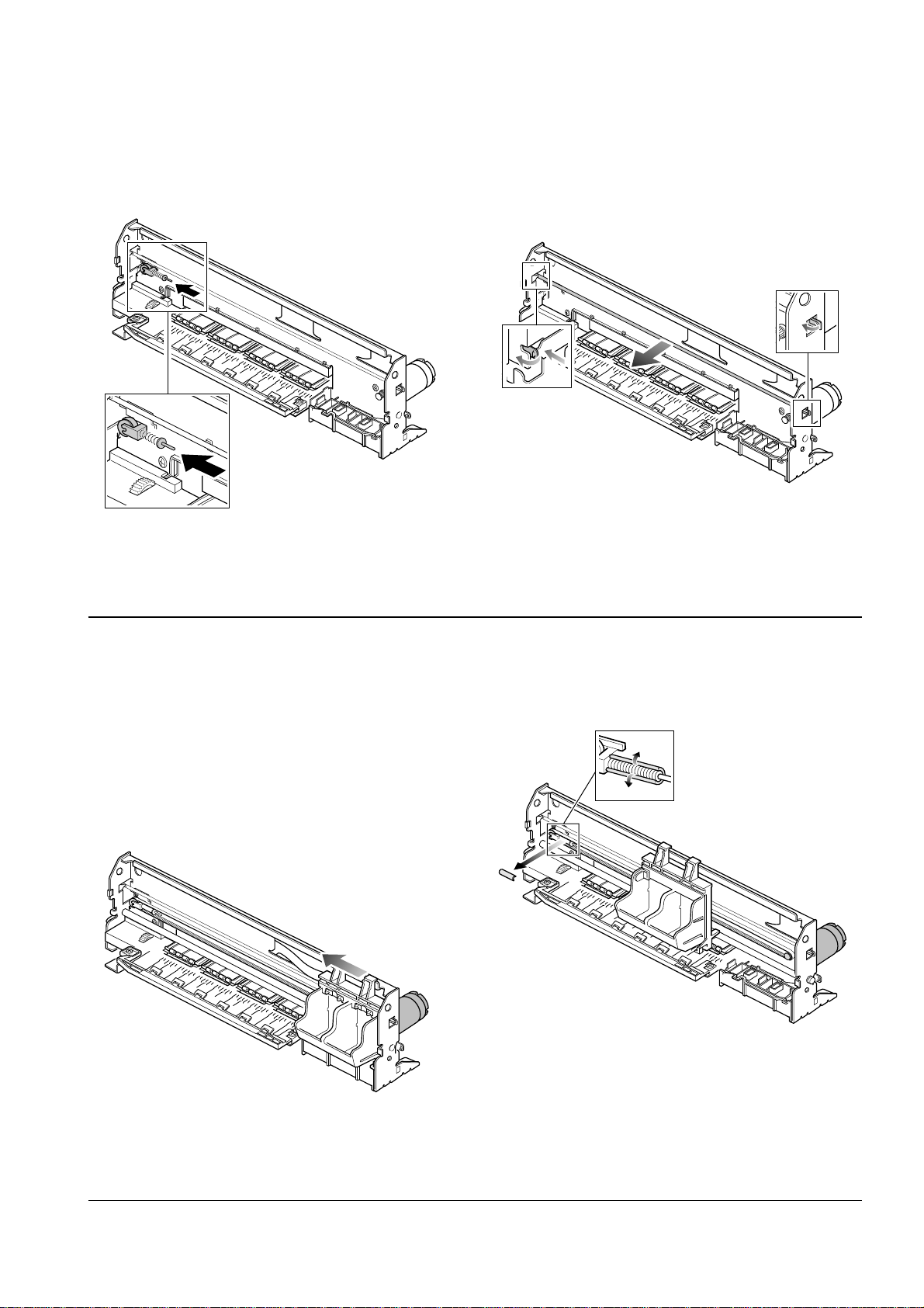
1. Before you disassemble the carrier motor
you should remove:
* All covers (See page 3-1, 3-9, 3-10)
* Scanner unit assembly (See page 3-2)
* Engine unit (See page 3-10)
2. Push the cartridge carrier to the direction of
arrow.
3. Remove the C-cap.
3-16 Carrier Motor
6. Push the holder pulley to the direction of
arrow and remove it from the main frame.
7. Unlatch the encoder by releasing both ends
hooked to the main frame using a sharp tool.
Take out the encoder.
Samsung Electronics
3-14
Disassembly and Reassembly
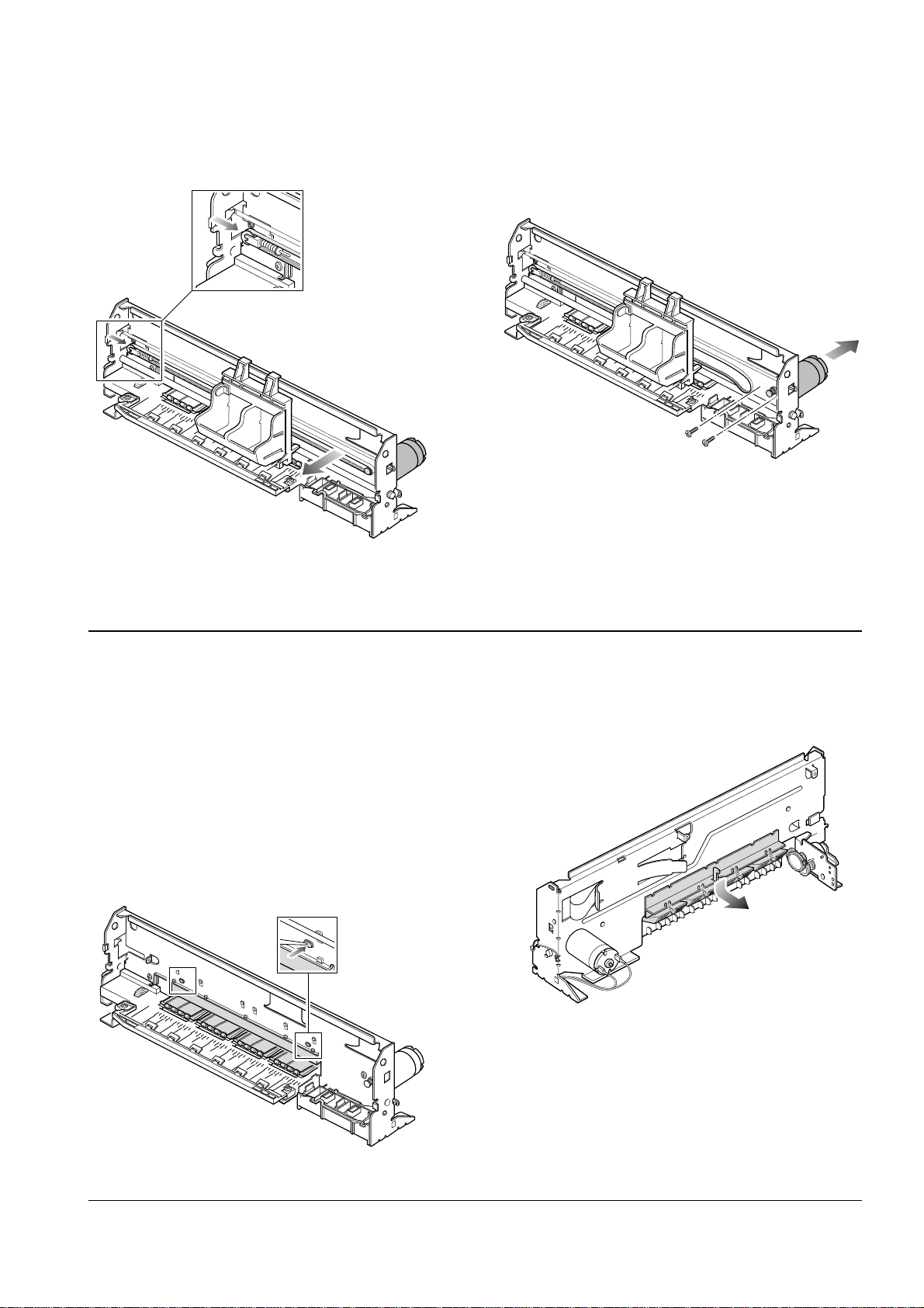
1. Before you disassemble the roller holder you
should remove:
* All covers (See page 3-1, 3-9, 3-10)
* Scanner unit assembly (see page 3-2)
* Engine unit (See page 3-10)
* FPC holder assembly (See page 3-11)
* Cartridge assembly (See page 3-12)
2. Unlatch the holder by pushing the parts
hooked to the main frame using a sharp tool.
3. Pull the holder downward and take it out from
the main frame.
3-17 Roller Holder
4. Push the holder pulley and remove the belt only. 5. Remove two screws securing the carrier motor
and take out the motor from the main frame.
Samsung Electronics
 Loading...