

Page 1

igh Resolution WDR Vandal-Resistant
H
Dome Camera
User Manual
SCV-3082
Page 2

H
igh Resolution WDR Vandal-Resistant
Dome Camera
User Manual
Co
pyright
©201 Samsung Techwin Co., Ltd. All rights rese rved.
ademark
Tr
The name of this product is the registered trademar k of Samsung Techwin Co., Ltd.
Other trademarks mentioned in this manual are the registered trademark of their respective company.
Restriction
msung Techwin Co., Ltd shall reserve the copyright of this document. Under no circumstances, this document
Sa
shall be reproduced, distribu ted or changed, partially or wholly, without formal authorization of Samsung Techwin.
sclaimer
Di
Samsung Techwin makes the best to verify the integrit y and correctness of the contents in this document, but
no formal guarantee shall be provided. Use of this document and the subsequent results shall be entirely on
the user’s own responsibility. Samsung Techwin reser ves the right to change the contents of this document
without prior notice.
Warranty
If the product does not operate properly in normal conditions, please let us know. Samsung Techwin will resolve
the problem for free of charge. The warrant y period is 3 years. However, the followings are excluded:
•
If the system behaves abnormally because you run a program irrelevant to the system operation.
•
Deteriorated per formance or natural worn- out in process of time
Design and specifications are subject to change without prior notice.
i
the registered logo of Samsung Techwin Co., Ltd.
s
Page 3

Before operating the camera, confirm the camera model and correct input power voltage.
To help you understand this manual thoroughly, we’ll introduce our model description.
■ SCV-3082 SERIES
• NTSC MODEL
• PAL MODEL
SCV-3082N SCV-3082P
■ MODEL DESCRIPTION
SCV-3082X
•
_
SIGNAL SYSTEM
•SIGNAL SYSTEM
→NTSC MODEL
N
P
→PAL MODEL
Page 4

safety information
CAUTION
RISK OF ELECTRIC SHOCK.
DO NOT OPEN
O REDUCE THE RISK OF ELECTRIC SHOCK, DO NOT REMOVE
CAUTION:
W
ARNING
To prevent damage which may result in fire or electric shock hazard, do not expose this
•
appliance to rain or moisture.
To prevent injury, this apparatus must be securely attached to the floor/wall in accordance
•
with the installation instructions.
WARNING
B
1.
e sure to use only the standard adapter that is specified in the specification sheet.
Using any other adapter could cause fire, electrical shock, or damage to the product.
2.
Incorrectly connecting the power supply or replacing battery may cause explosion, fire,
electric shock, or damage to the product.
3.
Do not connect multiple cameras to a single adapter. Exceeding the capacity may cause
abnormal heat generation or fire.
4.
Securely plug the power cord into the power receptacle. insecure connection may cause
fire.
5.
When installing the camera, fasten it securely and firmly. The fall of camera may cause
personal injury.
T
COVER (OR BACK) NO USER SERVICEABLE PARTS INSIDE. REFER
SERVICING TO QUALIFIED SERVICE PERSONNEL.
T
his symbol indicates that dangerous voltage consisting a risk of electric
shock is present within this unit.
his exclamation point symbol is intended to alert the user to the
T
presence of important operating and maintenance (servicing) instructions
in the literature accompanying the appliance.
4_ safety information
Page 5

D
6.
o not place conductive objects (e.g. screwdrivers, coins, metal parts, etc.) or containers
filled with water on top of the camera. doing so may cause personal injury due to fire,
electric shock, or falling objects.
Do not install the unit in humid, dusty, or sooty locations. doing so may cause fi re or
7.
electric shock.
8.
If any unusual smells or smoke come from the unit, stop using the product. in such case,
immediately disconnect the power source and contact the service center. continued use in
such a condition may cause fire or electric shock.
9.
If this product fails to operate normally, contact the nearest service center. never
disassemble or modify this product in any way. (samsung is not liable for problems caused
by unauthorized modifications or attempted repair.)
10.
W
hen cleaning, do not spray water directly onto parts of the product. doing so may cause
fire or electric shock.
CAUTION
1.
D
o not drop objects on the product or apply strong shock to it. Keep away from a location
subject to excessive vibrationor magnetic interference.
2.
Do not install in a location subject to high temperature (over 55°C), low temperature (below
-10°C), or high humidity. Doing so may cause fire or electric shock.
3.
If you want to relocate the already installed product, be sure to turn off the power and then
move or reinstall it.
4.
Remove the power plug from the outlet when then there is a lightning. Neglecting to do so
may cause fire or damage to the product.
5.
Keep out of direct sunlight and heat radiation sources. It may cause fire.
6.
Install it in a place with good ventilation.
7.
Avoid aiming the camera directly towards extremely bright objects such as sun, as this
may damage the CCD image sensor.
8.
Apparatus shall not be exposed to dripping or splashing and no objects filled with liquids,
such as vases, shall be placed on the apparatus.
9.
The Mains plug is used as a disconnect device and shall stay readily operable at any time.
10.
D
o not expose the camera to radioactivity. Radioactivity exposure may damage the CCD.
●
SAFETY INFORMA
TION
English_5
Page 6

safety information
FCC STATEMENT
T
his device complies with part 15 of the FCC Rules. Operation is subject to the following two
conditions :
This device may not cause harmful interference, and
1)
This device must accept any interference received including interference that may cause
2)
undesired operation.
CAUTION
his equipment has been tested and found to comply with the limits for a Class A digital
T
device, pursuant to part 15 of FCC Rules. These limits are designed to provide reasonable
protection against harmful interference when the equipment is operated in a commercial
environment.
This equipment generates, uses, and can radiate radio frequency energy and, if not
installed and used in accordance with the instruction manual, may cause harmful
interference to radio communications. Operation of this equipment in a residential area is
likely to cause harmful interference in which case the user will be required to correct the
interference at his own expense.
I
C Compliance Notice
This Class A digital apparatus meets all requirements of the Canadian
Interference.-Causing Equipment Regulations of ICES-003.
Correct
(
Applicable in the European Union and other European countries with separate collection systems)
This marking on the product, accessories or literature indicates that the product and its electronic accessories
(e.g. charger, headset, USB cable) should not be disposed of with other household waste at the end of their
working life. To prevent possible harm to the environment or human health from uncontrolled waste disposal,
please separate these items from other types of waste and recycle them responsibly to promote the sustainable
reuse of material resources.
Household users should contact either the retailer where they purchased this product, or their local government
office, for details of where and how they can take these items for environmentally safe recycling.
Business users should contact their supplier and check the terms and conditions of the purchase contract.
This product and its electronic accessories should not be mixed with other commercial wastes for disposal.
Correct
(
Applicable in the European Union and other European countries with separate battery return systems.)
This marking on the battery, manual or packaging indicates that the batteries in this product should not be
disposed of with other household waste at the end of their working life. Where marked, the chemical symbols
Hg, Cd or Pb indicate that the battery contains mercury, cadmium or lead above the reference levels in EC
Directive 2006/66. If batteries are not properly disposed of, these substances can cause harm to human health
or the environment.
To protect natural resources and to promote material reuse, please separate batteries from other types of waste
and recycle them through your local, free battery return system.
6_ safety information
Disposal of This Product
Electrical & Electronic Equipment)
(Waste
disposal of batteries in this product
Page 7
important safety instructions
Read these instructions.
1.
Keep these instructions.
2.
Heed all warnings.
3.
Follow all instructions.
4.
Do not use this apparatus near water.
5.
Clean only with dry cloth.
6.
Do not block any ventilation openings. Install in accordance with the manufacturer’s
7.
instructions.
Do not install near any heat sources such as radiators, heat registers, or other apparatus
8.
(including amplifiers) that produce heat.
Do not defeat the safety purpose of the polarized or grounding-type plug. A polarized plug
9.
has two blades with one wider than the other. A grounding type plug has two blades and
a third grounding prong. The wide blade or the third prong is provided for your safety. If
the provided plug does not fit into your outlet, consult an electrician for replacement of the
obsolete outlet.
rotect the power cord from being walked on or pinched particularly at plugs,
P
10.
convenience receptacles, and the point where they exit from the apparatus.
Only use attachments/accessories specified by the manufacturer.
11.
Use only with cart, stand, tripod, bracket, or table specified by the
12.
manufacturer, or sold with the apparatus.
nplug this apparatus when a card is used. Use caution when moving
U
13.
the cart/ apparatus combination to avoid injury from tip-over.
efer all servicing to qualified service personnel. Servicing is required when the apparatus
R
14.
has been damaged in any way, such as powersupply cord or plug is damaged, liquid has
been spilled or objects have fallen into the apparatus, the apparatus has been exposed to
rain or moisture, does not operate normally, or has been dropped.
Apparatus shall not be exposed to dripping or splashing and no objects
filled with liquids, such as vases, shall be placed on the apparatus
●
SAFETY INFORMA
TION
Samsung Techwin cares for the environment at all product manufacturing
stages to preserve the environment, and is taking a number of steps to provide
customers with more environment-friendly products.The Eco mark represents
Samsung Techwin’s will to create environment-friendly products, and indicates
that the product satisfies the EU RoHS Directive.
English_7
Page 8

contents
INTRODUCTION
9
INSTALLA
TION
13
CONNECTION
16
SETUP
18
TROUBLESHOOTING
35
SPECIFICA
TION
S
9
Featur
11
What’
12
Component names and
13
Installation
15
Adjust the panning and tilting
16
Connecting to Monitor
16
Connecting to Power
17
Using Coaxial Communications
18
Menu Configration
18
Menu Setup
35
T
36
Specifications
38
Dimension
es
s included
Functions
while watching the monitor
roubleshooting
8_ contents
36
Page 9

introduction
FEATURES
Ultra High Resolution
By adopting a diagonal 6mm (1/3”) 520K pixel (NTSC), 610K pixel (PAL) Color Double
Density CCD, the camera produces clear picture quality with a horizontal resolution of
650 TV lines for color and 700 TV lines for BW.
Excellent Sensitivity
The Built-in high sensitivity COLOR CCD produces a clear image.
-
-
lor :
0.1
Co
W :
.01 Lux (50IRE, @F1.2), 0.00002 LUX (SENS-UP, x512)
B/
0
Intelligence
ithout assistance from an external sensor, this camera independently detects and
W
traces objects while examining stillness and movement to activate the alarm.
SSNR3 (Samsung Super Noise Reduction) Function
The high-performance SV
afterimage to provide clear images even in dark environments.
Day & Night(ICR)
The camera identifies whether it is day or night and automatically switches to the
appropriate mode, depending on its environment. By day, the camera switches to color
mode in order to maintain optimal color. At night, it switches to B/W mode so as to obtain
better picture definition.
PROFILE
You can set a mode accor
- BASIC, DAY/NIGHT
PIP
Displays a full-size image along with the thumbnail.
SSDR(Samsung Super Dynamic Range)
For images with high contrast between bright and dark areas fr
conditions such as backlighting, this camera selectively illuminates darker areas while
retaining the same light level for brighter areas to even out the overall brightness.
WDR
By adopting a proprietary SV-V DSP chip, the camera delivers clear, high quality pictures
even when the scene is backlight, by increasing exposure in dark areas while decreasing
it in bright areas; a corrected image with clear details results.
PS(Virtual Progr
V
Adopting Samsung's unique development, the VPS(Virtual Pr
the sharpness of moving subject's outline. The VPS enables elective output in progressive
mode using the existing interlaced input and effectively enhances the sharpness of
captured pictures from video and still images. The function effectively removes blurred
outline problems resulting in excellent road monitoring and improved license plate
recognition.
Lux (50IRE, @F1.2), 0.0002LUX (SENS-UP, x512)
-V DSP chip ef
ding to the camera installation conditions.
, BACKLIGHT, ITS, INDOOR, USER
Scan)
essive
fectively removes low-light gain noise and
om difficult lighting
ogressive Scan) enhances
English_9
●
INTRODUCTION
Page 10

introduction
DIS (Digital Image Stabilizer)
The DIS function compensates for any camera movement, to produce more stable
pictures.
y
IP66 Approved/Dust and Rain Resistant
With dust and rain resistant design, the camera can be installed outside under
building eaves or places that are exposed to the dust and rain.
Miscellaneous Functions
HLC (High Light Compensation), SENS-UP, REVERSE, D-ZOOM, SHARPNESS and
PRIVACY functions are provided.
Communication
Coaxial communication methods are supported.
- Protocol: Pelco Coaxitron
D
OS
The camera’s OSD is complimented by 18 languages.
- NTSC: English, Korean, Japanese, Spanish, French, Portuguese, Taiwanese
- PAL: English, Chinese, German, Italian, French, Spanish, Russian, Czech, Polish,
Romanian, Serbian, Swedish, Danish, Turkish, Portuguese.
10_ introduction
Page 11

T’S INCLUDED
E
SPAÑOL
G
uía Rápida para la Configuración del SCV-3081
SCV-3081 Anleitung zur Schnelleinrichtung
DEUTSCH
➊
Domekuppel
➋
Abschirmkappe
➌
Supporto Pan : Für die Steuerung des Schwenkwinkels der Kamera.
➍
x3.9 Objektiv mit variabler Brennweite : 2.8 ~ 11mm (F1.2).
➎
Funktion-Setup-Schalter : Anzeigen des Bildschirmmenüs und Bewegen des Cursors in vier
Richtungen zur Statusbestä oder nach Änderung eines Elements.
➏
Video-Out-Anschlussbuchse : Über diesen Port werden Videosignale ausgegeben. Diesen Port mit
dem Port “Video IN” an einem Monitor verbinden.
➐
Drehbasis : Für die Steuerung des Drehwinkels der Kamera
➑
Netzeingang : Schließen Sie die für das jeweilige Modell angegebene Stromversorgung hier an.
➒
Erdungsanschluss
❿
D & N Eingang Anschlussterminal : Sie können zwischen Tag- und Nachtmodi umschalten, indem Sie ein
externes Signal an diesen Anschlussterminal anschließen.
⓫
MD Output Anschlussterminal :
Bewegungserkennungssignale werden durch diesen Anschluss ausgegeben.
⓬
Videoausgang für Anschluss von Monitor
➊
Cubierta del Domo
➋
Tapa Protectora
➌
Base de Paneo : Controla el ángulo de paneo de la cámara.
➍
Módulo del Lente Varifocal x3,9 : 2.8 ~ 11mm (F1.2).
➎
Botón de Configuración de Funciones : Muestra el menú en la pantalla y desplaza el cursor en las
cuatro direcciones para confirma estado o el cambio de un elemento seleccionado.
➏
Puerto de Salida de Video : Permite la salida de las señales de video. Conecte este puerto al puerto
de entrada de un monitor.
➐
Base de rotación : Commande de l’angle de rotation de la caméra.
➑
Terminal de entrada de alimentación : Conecte aquí la alimentación apropiada para cada modelo.
➒
Terminal de toma de tierra
❿
T
erminal de entrada D y N : Puede cambiar al modo Día y Noche conectando una señal externa a este
terminal.
⓫
Terminal de salida MD : La salida de las señales de detección de movimiento se realizan a través
de este terminal.
⓬
Terminal de Salida de Video al Monitor
EINST HAUPTMENÜ
1.LENS DC
2.BELICHTUNG
3.WEIβAB ATW
4.GEGENLICHT AUS
5.SSNR3 EIN
6.TAG/NACHT AUTO
7.PROFIL GRUND
8.SPEZIAL
9.BEENDEN SAVE
Ķ
Ķ
Ķ
Ķ
Ķ
Ķ
Ķ
Ķ
Ķ
ATW / AUßEN / INNEN / MANUELL / AWCĄSET
DC
H
ELLIGKEIT / SHUTTER / AGC / SENS-UP / ZURÜCK
AUS / BEN BLC / HLC / SSDR / WDR
EIN / AUS
SAVE / NOT SAVE / RÜCKS
GRUND / TAG/NACHT / GEGENLIGHT / ITS / INNEN / BEN
AUTO / EXTERN / COLOR / S/W
BILDEINST / TITEL KAM / SYNC / INTELLIGENCE / PRIVAT
/ DIS / SPRACHE / ZURÜCK
SAVE / NOT SAVE / RESET
CONFIG PRINCIPAL
1.LENTE DC
2.EXPOSIC
3.BAL BLAN ATW
4.CONTRALUZ OFF
5.SSNR3 ON
6.DIA/NOCHE AUTO
7.PROFIL BÁSICO
8.ESPEC
9.SALIR SAVE
D
C
BRILLO / SHUTTER / AGC / SENS-UP / VOLVER
ATW / EXTER / INTER / MANUAL / AWCĄSET
OFF / USUA BLC / HLC / SSDR / WDR
ON / OFF
BÁSICO / DIA/NOCHE / CONTRALUZ / ITS / INTER / USUA
AUTO / EXTERNO / COLOR / N/B
AJUST IMAG / TITULO CAM / SYNC / INTELIG. /
PRIVACIDAD / DIS / IDIOMA / VOLVER
Ķ
Ķ
Ķ
Ķ
Ķ
Ķ
Ķ
Ķ
Ķ
RE
D (MD_OUT
WHITE
(EXT_DN
)
BLACK (GND
)
BO
TT
O
M
➑
➏
➐
➌
⓬
❶
➍➎➋
⓫
❿
➒
RE
D
(M
D
_
OU
T
W
HI
T
E (E
XT
_D
N)
BL
A
CK
(GN
D
)
BOT
TOM
➑
➏
➐
➌
⓬
❶
➍➎➋
⓫
❿
➒
WHA
heck if the following items are included in the product package.
C
High Resolution WDR Vandal-Resistant
Dome Camera
User Manual
SCV-3082
U
ser Manual Quick Set-up Guide
Video Output Cable M4 Tapping Screw
W
rench
High Resolution WDR Vandal-
SCV-3082
Resistant Dome Camera
Quick Set-up Guide
emplate
T
SCV-3082
●
INTRODUCTION
English_11
Page 12

introduction
RED (MD_OUT
WHITE (EXT_DN)
BLACK (GND)
BOTTOM
COMPONENT NAMES AND FUNCTIONS
OVERVIEW
➌
2
❶
5
➏
⓬
⓫
❿
➒
➑
❶ Dome Cover
❷
Shield Case
❸
an Base : control panning angle of camera
P
❹
3
.9 Vari-focal Lens Module 2.8 ~ 11.0mm (F1.2)
❺
F
unction Setup Switch : Display the OSD menu and move the cursor up, down,
❻
V
ideo Output Terminal to Monitor
➐
R
otate Base : control rotating angle of camera.
➑
ower Input Connector
P
➒
Ground Terminal
❿
D & N Input Terminal : You can switch to Day & Night Mode by connecting
⓫
D Output Terminal: Motion detection signals are output through this terminal.
M
⓬
V
ideo Output Jack
M
12_ introduction
an external signal to this terminal.
e sure to connect the Day & Night input terminal to GND when using an external input.
B
➐
left,and right amend or confi rm changes.
4
Page 13
installation
DISASSEMBLING
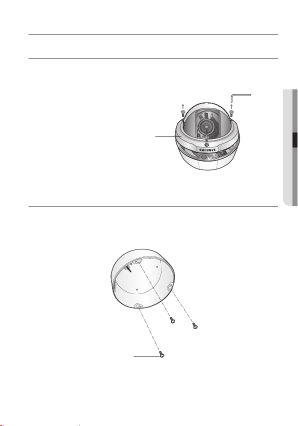
sing the L-wrench provided, loosen 3 screws by turning them counterclockwise and
U
separate the dome cover.
ome Cover
D
INST
ALLING THE CAMERA ON A CEILING OR WALL
Drill holes on the ceiling by matching to the holes on the case bed, and insert
1.
plastic anchors (HUD 5) (not included) fully into the holes. Fix the case bed on
the ceiling by using T
apping screws (TH M4 x L30). (3 places)
●
INST
ALLATION
T
apping screw
English_13
Page 14
installation
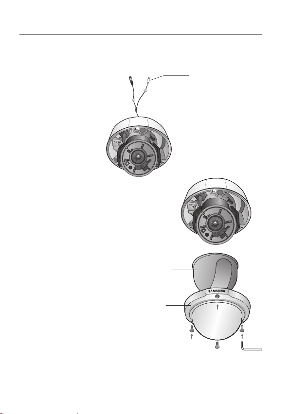
Connect Power and video cables and arrange them thr
2.
to pass when mounting the main body on the mounting bracket, note that not
to damage or squeeze the cables.
ower input terminal
P
3.
Adjust the lens in a desired direction.
4.
Secure the Shield case to the main unit.
5.
Assemble the camera on its mounting bracket
with the three screws using L Wrench (included).
S
hield case
D
ome cover
ough the hole you want
ideo output jack
V
M
14_ installation
he installation should be done by qualifi ed service personnel or system installers.
T
If the ceiling material is not strong enough to hold the installation screws, the camera may fall off.
Reinforce the ceiling as needed.
Page 15
ADJUST THE P
BOTTOM
P
1.
2.
ANNING, TILTING & ROTATION WHILE WATCHING THE MONITOR
3˚
1
76˚
1
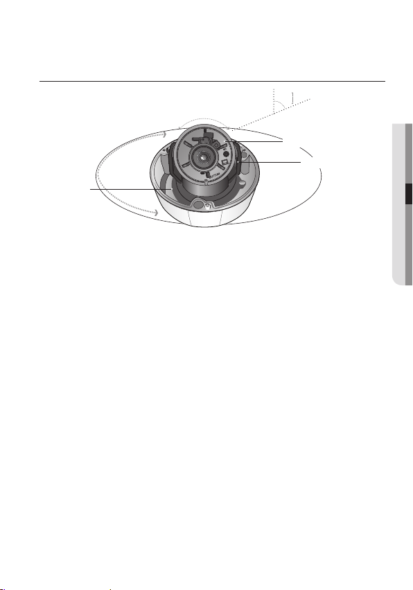
an Base
176˚
ou can adjust camera to any direction by using Pan, Tilt, Rotate mechanism.
Y
Pan Base moves by 176˚ to each side dir
Tilt Base covers total 73˚ angle(0˚ ~ 73˚).
Rotate Base moves by 174° to each side direction and 348° on the whole.
1
74˚
74˚
ection and 352˚ on the whole.
Methods of adjustment
The case of wall installation
1
After mounting the camera on a wall, adjust the panning angle so that the
7
R
otate Base
correct viewing angle is attained and the titling is correctly orientated.
2
And then adjust the tilting angle by rotating the tilt base.
➌
Loosen the rotate base hold screw and adjust rotate base for the best view
4
Tighten rotate base securing screw.
The case of ceiling installation
1
After mounting the camera on a ceiling, adjusting the panning angle to the
correct viewing position by rotating the pan base.
2
And then adjust the tilting angle by rotating the tilt base.
➌
Loosen the rotate base hold screw and adjust rotate base for the best view
4
Tighten pan and tilt securing screw.
hen you want to adjust the Pan/Tilt/Rotate Base, loosen, adjust and then tighten the Pan/Tilt/
W
M
Rotate Base screws.
ilt Base
T
●
INST
ALLATION
English_15
Page 16
connection
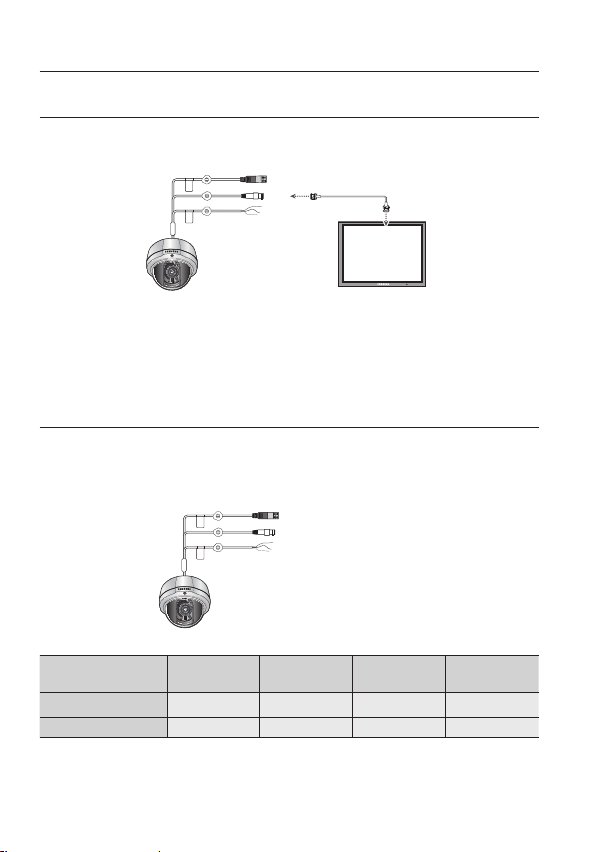
CONNECTING TO MONITOR
onnect the VIDEO-OUT jack to the VIDEO-IN jack of monitor.
C
CCTV Camera
As the connecting method varies with the instruments, refer to the manual supplied
with the instrument.
Only connect the cable when the power is turned off.
If necessary, you can connect the monitor to the REMOTE jack on the back of your
camera.
Monitor
CONNECTING TO POWER
C
onnect the adaptor to the power input connector as shown in the fi gure below.
The recommended adaptor specif cation for SCV-3082N/3082P is DC 12V / 500mA or AC 24V /
500mA.
Power Input
----
Terminal
W
hen the resistance value of copper wire is at [20°C(68°F)]
C
opper wire size
(AWG)
esistance (Ω/m) 0.078 0.050 0.030 0.018
R
#24 (0.22mm
Voltage Drop (V/m) 0.028 0.018 0.011 0.006
As shown in the table above, voltage decreases as the wire gets longer. Therefore use of
an excessively long adaptor output line for connection to the camera may
affect the performance of the camera.
16_ connection
2
) #
22 (0.33mm
2
) #
20 (0.52mm
2
) #
18 (0.83mm
2
)
Page 17
MENU
SEARCH
M
UL
TI
REC
MEN
U
P
RESET
GRO
UP
TRACK
CAM
1
2
3
4
5
6
7
8
9
0
MO
N
CLOSE
OPEN
NEAR
FAR
WIDE
TELE
PTZ
DVR
MTX
SETUP
ESC
FUNC
ENTER
1 2 3 4
5 6 7 8
9 10 11 12
13 14 15 16
A
LARM
HDD N
ETWORK BACKUPREC
D
VD RECORDER
REC
ZOOM
MODE
FRE
EZE
AU
DIO
BAC
KUP
AL
RAM
SEAR
CH
TELE WIDE VIEW PRESET
M
ENU
RE
TURN
USB
O
PEN/CLOSE
Standard voltage for camera operation : DC 12V ±10%, AC 24V ± 10%
*
* There may be some deviation in voltage drop depending on the type of wire and the
manufacturer.
e sure to connect power only after all the installation is complete.
B
M
Note that AC/DC adaptor is not supplied with camera.
Ground should be connected to the GND terminal.
●
CONNECTION
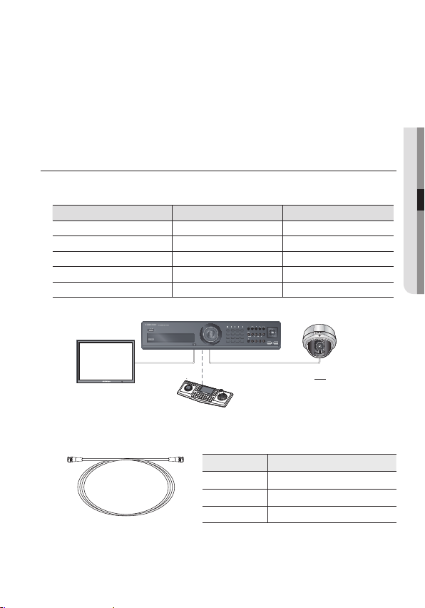
USING COAXIAL COMMUNICA
Coaxial Communications System
OSD Contr
ol method
AMERA DVR CONTROLLER
C
TIONS
SET MENU/ENTER OSD KEY
UP UP KEY JOYSTICK UP
DOWN DOWN KEY JOYSTICK DOWN
LEFT LEFT KEY JOYSTICK LEFT
RIGHT RIGHT KEY JOYSTICK RIGHT
D
VR
: BNC
•
---- : RS-485
•
ideo Cable
- V
The camera’s video output port is connected to the monitor with a BNC coaxial
cable, shown below : If the distance between the camera and the monitor exceeds
the recommended maximum, please use an auxiliary video amp.
istance Recommended Cable Specifi cation
D
300m 3C2V(RG-59/U)
450m 5C2V(RG-6/U)
It is recommended that pure copper coax cable is used and not copper coated steel, as this will
M
cause issues with the communication over the coaxial cable.
To ensure image quality, please connect only one-way video output from camera to other video
display devices.
600m 7C2V(RG-11/U)
English_17
Page 18
setup
W
HITE BAL
●
A
TW
●
O
UTDOOR
●
I
NDOOR
●
M
ANUAL
●
A
WC
→
S
ET
B
ACKLIGHT
●
O
FF
●
U
SER BLC
●
H
LC
●
WDR
S
SNR3
●
O
N
●
O
FF
D
AY/NIGHT
●
A
UTO
●
E
XTERN
●
C
OLOR
●
B
/W
S
PECIAL
●
I
MAGE ADJ
●
C
AM TITLE
●
S
YNC
●
I
NTELLIGENCE
●
P
RIVACY
●
D
IS
●
PROFILE
●
R
ETURN
E
XIT
●
S
AVE
●
N
OT SAVE
●
R
ESET
MENU SETUP
U
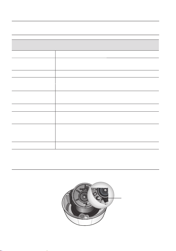
se the Function Setup switch beside of the lens.
BOTTOM
F
unction Setup switch
SSDR
●
O
FF
●
O
N
MENU CONFIGRATION
●
LENS
EXPOSURE
C
D
●
RIGHTNESS
B
●
SENS-UP
etup Menu
S
●
HUTTER
S
●
RETURN
●
GC
A
18_ setup
Page 19
English_19
●
SETUP
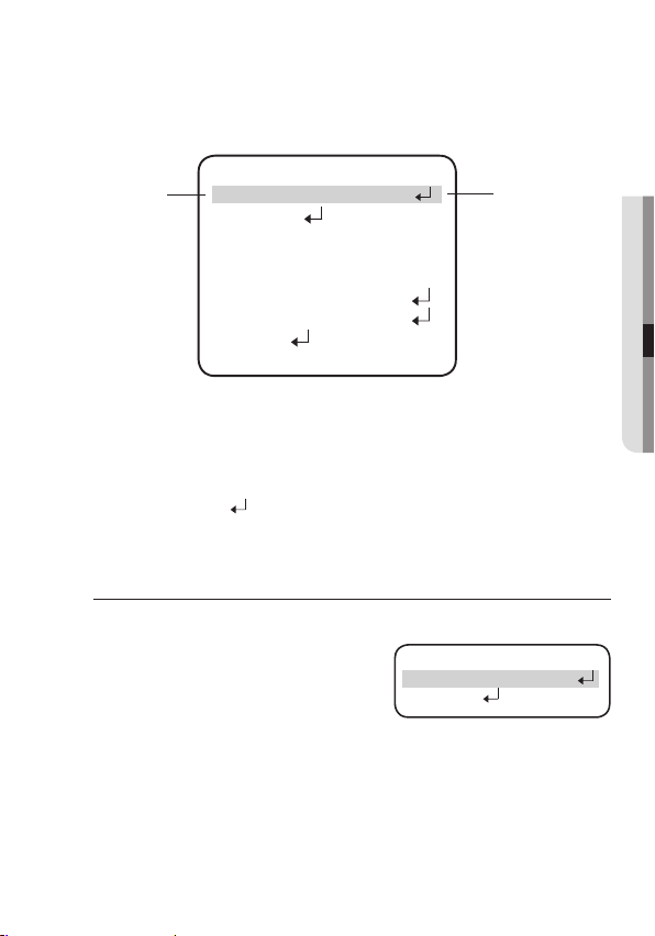
Press the Function Setup switch.
1.
Main setup menu is displayed on the monitor scr
AIN SETUP
elect the function
S
by moving up or
down direction of
function setup switch.
▶ 1
2
4.
5
6
9
Select a desir
2.
Place the cursor over a desir
Set up a selected item by using the Function Setup switch.
3.
o finish the setting, select ‘EXIT’ and press the Function Setup switch.
T
4.
M
ed function using the Function Setup switch.
A
n item with the icon also has sub menus. To select a sub menu, select an item with the icon
and press the Function Setup switch.
An item with the - - - icon is unavailable due to function settings.
M
.LENS DC
.EXPOSURE
3.
SSDR
.
.
.
7
WHITE BAL
BACKLIGHT
ON
SSNR3
DAY/NIGHT
8.SPECIAL
S
.EXIT
ed item.
ON
AUTO
OFF
A
TW
O
AVE
een.
FF
C
hange the status
by moving the
setup switch left or
right.
LENS
U
sing this function, you can control the screen brightness.
1.
When the SETUP menu screen is displayed,
select‘LENS’by using the Function Setup
switch so that the arrow indicates‘LENS’.
2.
The Lens mode has sub menu site as listed
below.
- BRIGHTNESS : Adjusts the video brightness.
- FOCUS ADJ : To adjust the lens focus correctly, you must activate the Focus
Settings mode. To activate the Focus Settings mode, adjust the lens focus,
and then deactivate the settings mode.
- RETURN : Select this to save the changes in the DC LENS menu and return to
the SETUP menu.
▶ 1.LENS DC
2.EXPOSURE
M
AIN SETUP
Page 20
setup
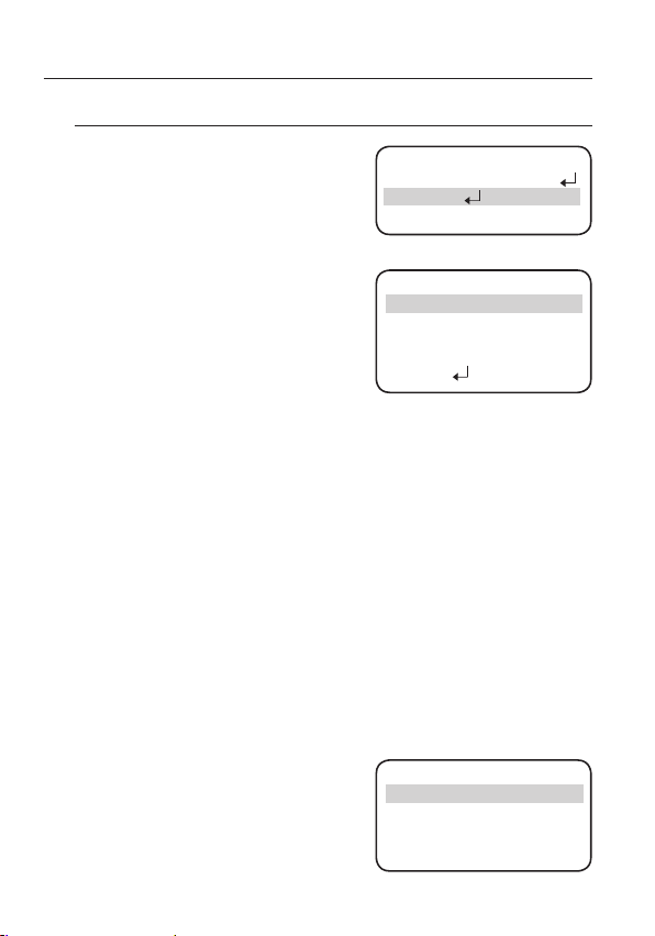
EXPOSURE
W
1.
hen the SETUP menu screen is displayed,
select EXPOSURE by using the Function
Setup switch so that the arrow indicates
'EXPOSURE'.
2.
Select a desired mode using the Function
Setup switch.
BR
SHUTTER : You can select shutter mode.
ESC : Select this to contr
-
MANUAL :
-
A.FLK :
-
-
---: Shutter speed is fixed at 1/60sec(1/50sec).
M
: Adjusts the video brightness.
IGHTNESS
speed automatically. If ESC is
selected, the shutter speed is
automatically controlled depending on the ambient illumination of the subject.
Y
ou can control shutter speed manually.
(NTSC MODEL : 1/60~1/120,000 sec, P
Select this when you experience pictur
there is a clash with the installed lighting frequency.
W
hen the SHUTTER is set to ESC after selecting the Internal Synchronization Type, the picture may
become unstable if the camera faces a bright fluorescent light. Therefore, take care when choosing
the installation position.
When the SHUTTER is set to MANUAL or A.FLK mode, SENS-UP will be disabled.
Set the shutter mode to --- if color rolling occurs.
ol the shutter
M
AIN SETUP
.LENS DC
1
▶ 2
.EXPOSURE
3
.SSDR
RIGHTNESS
B
.
▶ 1
2
.SHUTTER
.AGC
3
H
4
.SENS-UP
5.RETURN
XPOSURE SETUP
E
IIIIIIIIIIIIIIIIIIIII
-
O
O
FF
25
--
IGH
FF
AL MODEL : 1/50~1/120,000 sec)
e flicker, this happens when
20_ setup
A
GC (AUTO GAIN CONTRO
L)
: The higher the gain level, the brighter the scr
but the higher the noise.
-
OFF : Deactivates the AGC function.
Allows automatic gain contr
-
LOW :
Allows automatic gain contr
-
HIGH :
SENS-UP
: When it is night or dark, the
ol from 5.3dB to 32dB.
ol from 5.3dB to 37dB.
camera automatically detects the
light level and maintains a clear
pictur
e if this mode is activated.
-
OFF : Deactivates the SENS-UP function.
-
AUTO : Activates the SENS-UP function.
▶ A
x
UTO
Press SET to Return
een
IMIT
L
2
Page 21
English_21
●
SETUP
URN
(
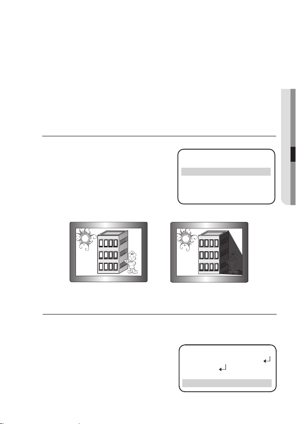
Samsung Super Dynamic Range)
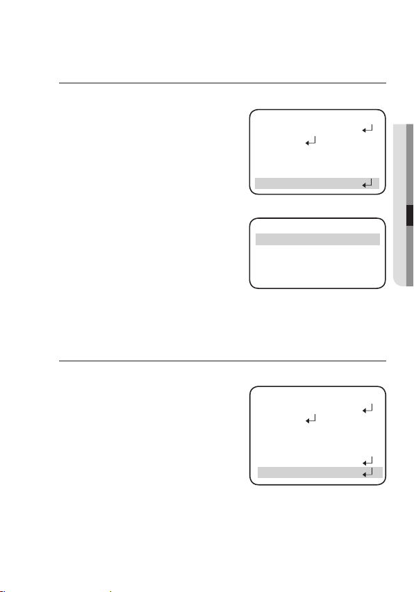
S
SDR illuminates darker areas of an
a
nd dark areas.
S
SDR OFF
SSDR ON
S
SDR SETUP
▶
LEVEL
IIIIIIIIIIIIIIIIIIIII
8
Press SET to Return
i
mage
w
hile retaining the same light level
f
or brighter
areas to even out the overall
brightness of
i
mages with high contrast
b
etween bright
and dark areas.
U
se the Function Setup
switch to
c
hange the SSDR level in the
sub menu
a
ccording to the contrast
between bright
RET
: Select this to save the changes in the EXPOSURE menu and r
the SETUP menu.
If you set the Function Setup switch to 'AUTO' mode, You can adjust the brightness by increasing
M
or decreasing the limit value. (x2~x512)
N
ote that the higher the SENS-UP level, the brighter the screen, but the more likely it is that an
after-image will appear.
Although Noise, Spots, and Whitish symptoms may occur in SENS-UP operation when the
sens-up level is increased, this is normal.
SSDR
WHITE BAL (WHITE BALANCE)
U
se the White Balance function to adjust the screen color.
1.
When the SETUP menu screen is displayed, select ‘White Bal.’ by using the
Function Setup switch so that the arrow
indicates ‘White Bal.’.
2.
Select a desired mode using the Function
Setup switch.
※ Select one of the following 5 modes, as
appropriate for your purpose.
1.LENS DC
2.EXPOSURE
▶
4.
.SSDR
3
HITE BAL
W
AIN SETUP
M
A
eturn to
O
FF
TW
Page 22
setup
ATW : Se
M
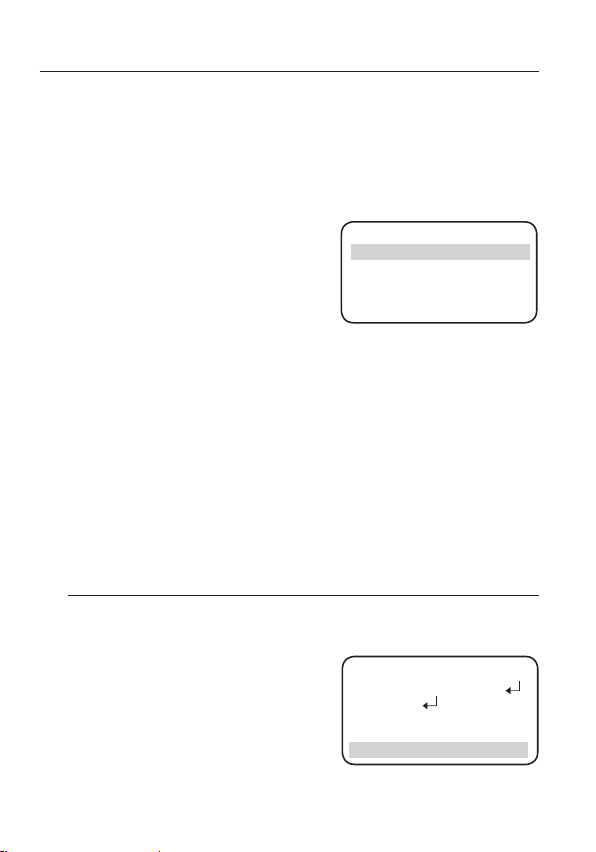
BACKLIGHT
is camera is designed so that it delivers a distinctive subject and background at
Th
the same time, even when the subject is in backlight, unlike conventional cameras, by
adopting a proprietary SV-V DSP chip.
When the SETUP menu screen is displayed,
1.
select ‘BACKLIGHT’ by using the Function
Setup switch so that the arrow indicates
BACKLIGHT .
Se
2.
switch depending on the camera purpose.
lect this when the color temperature is between 1,700°K and 11,000°K.
OU
: Select this when the color temperature is between 1,700°K and
TDOOR
11,000°K.(sodium light inclusion)
Select this When the color temperatur
e of environment surrounding
the subject is out of the control range (e.g. clear sky, or sunset)
DOOR
IN
:
Select this when the color temperature is between 4,500°K and 8,500°K.
MAN
:
Select this to fine-tune White
UAL
Balance manually. Set White
Balance first by using the A
or AWC mode. After that switch
to MANUAL mode, fine-tune the
White Balance and then press the
TW
▶ RED GAIN
BLUE GAIN
MANUAL
WB
IIIIIIIIIIIIIIIIIIIIIIIIIIII
IIIIIIIIIIIIIIIIIIIIIIIIIIII
Press SET to Return
Function Setup switch.
C→SET
AW
: To find the optimal luminance level for the curr
point the camera towards a sheet of white paper and press the
ent environment,
Function Setup switch. If the environment changes, readjust it.
White Balance may not work properly under the following conditions. In this case select the AWC
mode.
1
When the color temperature of the environment surrounding the subject is out of
the control range (e.g. clear sky or sunset).
2 Wh
en the ambient illumination of the subject is dim.
➌
If
the camera is directed towards a fluorescent light or is installed in a
place where illumination changes dramatically, the White Balance
operation may become unstable.
MA
IN SETUP
SSDR
3.
4.WHITE BAL ATW
lect a desired mode using the Function Setup
1.LENS DC
2.EXPOSURE
▶ 5.BACKLIGHT
23
24
5
5
O
FF
OFF
22_ setup
Page 23
ER BLC
M
ASK COLOR/TONE :
T
OP/BOTTOM/LEFT/RIGHT :
A
djust the area to be enhanced.
-
-
C
hange the color / brightness of the masking
area. (Black, Red, Blue, Cyan, Magenta)
OFF :
Not being used
US
: Enables a user to dir
ectly
select a desired area from a
picture, and to view the area
more clearly.
-
LEVEL : Adjust level of the BLC function.
-
TOP/BOTTOM/LEFT/RIGHT :
Adjust the ar
ea to be enhanced.
▶ 1.LEVEL
2.TOP
3.BOTTOM
4.LEFT
5. RIGHT
6. RETURN
LC SETUP
B
IIIIIIIIIIIIIIIIIIIII
IIIIIIIIIIIIIIIIIIIII
IIIIIIIIIIIIIIIIIIIII
IIIIIIIIIIIIIIIIIIIII
M
IDDLE
1
2
5
●
0
9
SETUP
70
50
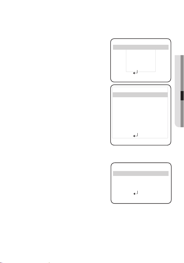
HLC (High Light Compensation) :
This function masks the str
minimize white out due to over exposure and
preserve much of the on-screen details when
the camera aims a strong light source.
-
EVEL : Adjusts the brightness level of a
L
monitoring area.
-
LIMIT : Enable to change the operating
condition.
W
WDR:
hen there are both bright
a
nd dark areas at the same time, this
m
ode makes both areas distinctive.
S
elect 'WDR' to adjust the WDR
L
IMIT and LEVEL.
IMIT : Adjust the WDR Sensitivity by
- L
- LEVEL :
selecting LOW, MIDDLE or
H
IGH.
Adjust the WDR Brightness by
ong light to
LC SETUP
H
▶ 1. LEVEL
2. LIMIT
3. MASK COLOR BLACK
4. MASK TONE
5.TOP
6.BOTTOM
7.LEFT
8.RIGHT
N
IGHT ONLY
IIIIIIIIIIIIIIIIIIIII
IIIIIIIIIIIIIIIIIIIII
IIIIIIIIIIIIIIIIIIIII
IIIIIIIIIIIIIIIIIIIII
IIIIIIIIIIIIIIIIIIIII
M
IDDLE
9. RETURN
W
DR SETUP
1.LIMIT
▶
2.LEVEL
3.MODE INDOOR
4.ANTI ROLLING
5. RETURN
IIIIIIIIIIIIIIIIIIIII
M
IDDLE
controlling the bar from 1 to 10.
- MODE : Indoor and outdoor backlight conditions ar
- ANTI ROLLING : Rolling caused around a fluorescent lamp is improved.
e appropriately selected.
English_23
1
210
O
5
10
05
1
0
5
FF
Page 24
setup
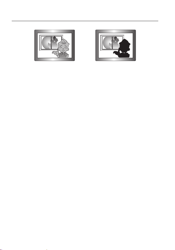
< WDR ON >
ecause there can be a difference in the effectiveness of HLC according to the amount of light
B
M
area in the screen, optimize the installation angle for the best HLC performance.
n a dark environment, the HLC is only activated when a high light that is larger than a certain area
I
is present.
The HLC is not activated in day light or when bright light is not present at night. (In NIGHT ONLY
mode).
When using the WDR function, the shutter is only available with the fixed (---) mode.
Since the performance of the WDR function may be affected by the area of the bright part of the
screen, optimize the installation angle for the best WDR performance.
If you increase LIMIT, the screen display may be distorted.
If you use the VPS (Virtual Progressive Scan) function, the CCD reads differently so you can not use
WDR simultaneously. If you set VPS to ON, WDR will be automatically set to FIXED Mode.
< WDR OFF >
24_ setup
Page 25
English_25
●
SETUP
SSNR3
his function reduces the background noise in a low luminance environments.
T
hen the SETUP menu screen is displayed,
W
1.
select 'SSNR3' by using the Function Setup
switch so that the arrow indicates 'SSNR3' .
elect a desired mode using the Function
S
2.
Setup switch.
OFF
: Deactivates SSNR3 so that noise is
S
et the SSNR3 mode to 'ON' and press the
3.
Function Setup switch. Then you can adjust
the noise reduction level.
M
educed.
not r
ON : Activates SSNR3 so that noise is r
ou cannot set the SSNR3 to 'ON' or 'OFF' when the AGC mode of the EXPOSURE menu is 'OFF'.
Y
hen adjusting the noise reduction level of the SSNR3 mode, remember that the higher the level
W
1
2
5.BACKLIGHT OFF
▶ 6.SSNR3 ON
educed.
▶ L
AIN SETUP
M
.LENS DC
.EXPOSURE
3
.SSDR
4.WHITE BAL ATW
SSNR3
IIIIIIIIIIIIIIIIIIIII
EVEL
Press SET to Return
set, the more the noise level will be reduced but that after image may also occur.
DAY/NIGHT
Y
ou can display pictures in color or black and white.
1.
When the SETUP menu screen is displayed,
select ‘DAY/NIGHT’ by using the Up and
Down buttons so that the arrow indicates
‘DAY/NIGHT’.
2.
Select a desired mode using the Left and
Right buttons according to the picture
display you want.
1.LENS DC
2.EXPOSURE
▶
AIN SETUP
M
3
.SSDR OFF
.WHITE BAL ATW
4
5.BACKLIGHT OFF
6.SSNR3 ON
7.DAY/NIGHT AUTO
OFF
1
5
: T
AUTO
he mode is switched to ‘Color’ in a normal environment, but switches to
‘B/W’ mode when ambient illumination is low. To set up the switching time
for AUTO mode, press the Function Setup
s
witch. You can turn on or off
the burst signal on B/W mode.
Page 26
setup
-
-
-
EXTER
COLO
B/
M
UTO SETUP
▶1.BURST MODE ON
2.COLORB/W
3.B/WCOLOR
DWELL TIME
4.RETURN
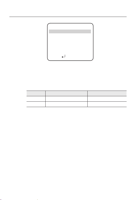
BURST MODE : Y
DWELL TIME :
DURATION :
ight levels are often site dependant.
※ L
N: This mode allows you to apply a desired filter to external signals.
Y
ou can select the duration time about changing the
day/night mode.
→3s, 5s, 7s, 10s, 15s, 20s, 30s, 40s, 60s
ou can select the brightness level at which the camera
Y
switches from day to night mode.
Fast 2.5 lux 5 lux
Slow 1 lux 7 lux
A
DURATION
DWELL TIME
DURATION
F
5
F
1
ou can turn on or off the burst signal on B/W mode.
olor → B/W B/W → Color
C
AST
SEC
AST
0 SEC
R: The picture is always displayed in color.
W: The picture is always displayed in black and white.
You can turn on or off the burst signal on B/W mode.
W
hen AGC in the EXPOSURE menu is ‘OFF’, ‘---’ mode operates as selecting ‘COLOR’ mode and
‘AUTO’ mode cannot be selected.
Be sure to connect the Day & Night input terminal to GND when using an external input.
The OSD key does not work for 3 seconds when switching to Color or B/W, to ensure stable
camera operation.
26_ setup
Page 27
English_27
●
SETUP
SPECIAL
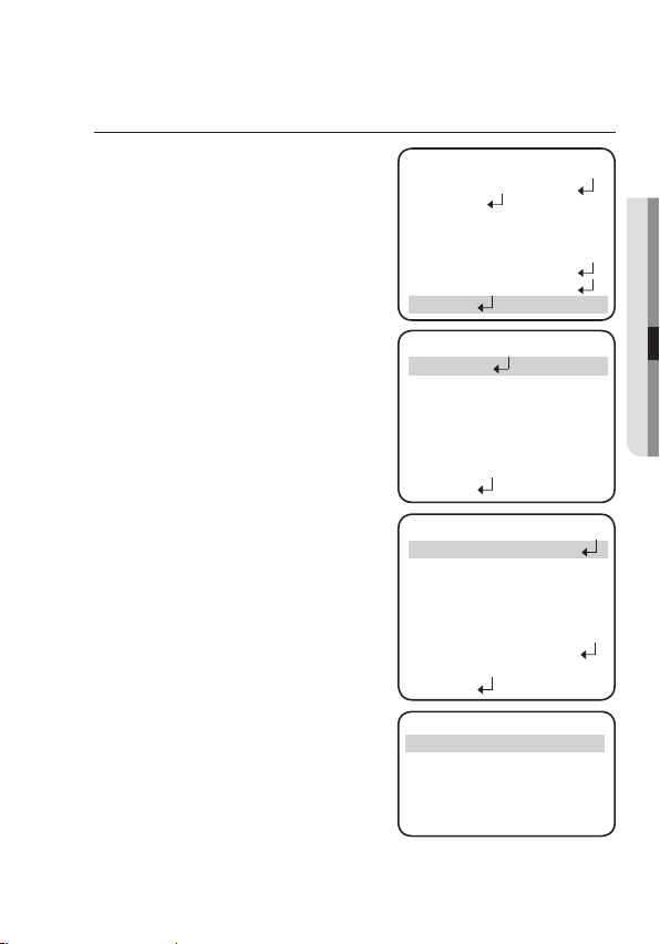
W
1.
hen the SETUP menu screen is displayed,
select ‘SPECIAL’ by using the Function Setup
switch so that the arrow indicates ‘SPECIAL’.
2.
Select a desired mode using the Function
Setup switch.
2
IMAGE ADJ :
1) When the SPECIAL menu screen is
)
Monitor
of video appropriate to your monitor.
-
-
-
VPS(Virtual Progressive Scan) : This is
an advanced technology that reproduces a
sharp progressive image. This is appropriate
to high quality recording and file transfer via
the Internet.
-
-
displayed, select ‘IMAGE ADJ’ by using
the Function Setup switch so that the
arrow indicates ’IMAGE ADJ‘.
Select a desired mode using the Function
Setup switch.
: Please change the settings value
LCD : Please select this menu item when
using an LCD monitor.
You can change the gamma, PED
level and color gain in the sub
menus.
CRT : Please select this menu item when
using a CRT monitor. You can
change the PED level, color gain in
the sub menus.
USER : Please use this menu item when
using a monitor other than standard ones. You can change the
gamma, PED level and color gain
in the sub menus.
OFF : Selects 2:1 Interlaced Scan as the Imaging Method.
ON : Selects Pr
ogressive Scan as the Imaging Method.
M
1.LENS DC
2.EXPOSURE
▶8.SPECIAL
▶ 1.IMAGE ADJ
2.CAM TITLE OFF
3.SYNC INT
4.INTELLIGENCE OFF
5.PRIVACY OFF
6.DIS OFF
7.PROFILE BASIC
8.RETURN
▶ 1. MONITOR LCD
2.VPS OFF
3.REVERSE OFF
4.PIP OFF
5.D-ZOOM OFF
6.FONT COLOR BLUE
7.SHARPNESS ON
8.LANGUAGE
9.RETURN
▶ GAMMA
PED LEVEL
AIN SETUP
3.SSDR
4.WHITE BAL ATW
5.BACKLIGHT OFF
6.SSNR3 ON
7.DAY/NIGHT AUTO
S
PECIAL
I
MAGE SETUP
ENGLISH
LCD MONITOR
0.55
COLOR GAIN
RESET
Press SET to Return
IIIIIIIIIIIIIIIIIIIII
IIIIIIIIIIIIIIIIIIIII
OFF
14
5
Page 28
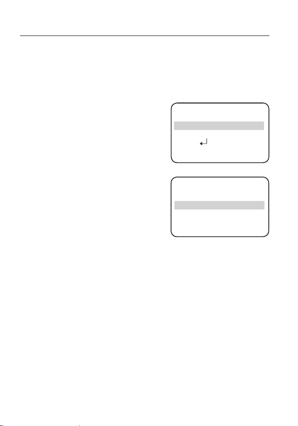
setup
REVERSE : You can reverse the picture.
-
-
-
-
PIP(Picture in Picture) : Displays a full-
size image along with the thumbnail to
provide more detailed information. The
position of the thumbnail is adjustable.
D-ZOOM : You can use a digital zoom of
x1 ~ x16.
FONT COLOR: You can change the OSD
font color. (White, Yellow, Green, Red, Blue)
SHARPNESS:
LANGUAGE
-
-
RETURN: Select this to save the settings
M
OFF : You don’t reverse the picture.
H-REV : You can flip the picture horizontally on the screen.
V-REV : You can flip the picture vertically on the screen.
HV-REV : You can flip the picture horizontally and vertically on the screen.
1.X POS
2.Y POS
3. RETURN
PIP SETUP
IIIIIIIIIIIIIIIIIIIII
IIIIIIIIIIIIIIIIIIIII
17
17
As you increase this value,
the picture outline becomes
stronger and clearer. Adjust
this value appropriately
depending on the sharpness
▶ LEVEL
of the picture.
:
You can select the menu
language according to your
requirements.
NTSC : Korean, English, French, Spanish, Japanese, Portuguese
SHARPNESS
IIIIIIIIIII
Press SET to Return
IIIIII
IIIII
10
, Taiwanese
PAL : English, Chinese, German, Italian, French, Spanish, Russian, Czech,
Polish, Romanian, Serbian, Swedish, Danish, Turkish, Portuguese
for the IMAGE ADJ menu and to
return
to the SPECIAL menu.
When the V-REV or H-REV mode is enabled, the text on the screen does not flip.
If you increase the SHARPNESS level too high, the picture may become distorted or noise may
appear.
28_ setup
Page 29
English_29
●
SETUP
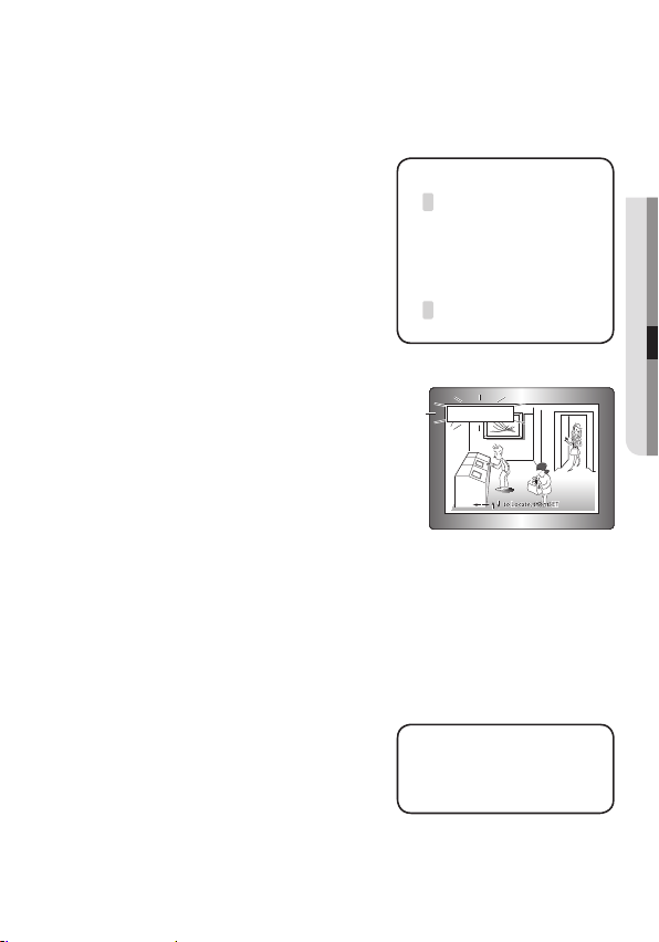
CAM TITLE
If you enter a title, the title will appear on the monitor
:
1
If the SPECIAL menu screen is
displayed, use the Function Setup
switch so that the arrow indicates
‘CAM TITLE’.
2 Set it to ‘ON’ by using the Function
Setup switch.
➌ Press the Function Setup switch.
se the Function Setup switch to
4
U
move to a desired letter and select
by pressing the switch.
the letter
Repeat this to enter multiple letters. You can enter
.
CAMERA TITLE SETUP
B C D E F G H I J K L M
A
N O P Q R S T U V W X Y Z
a b c d e f g h i j k l m
n o p q r s t u v w x y z
- . 0 1 2 3 4 5 6 7 8 9
← → C L R P O S E N D
_ _ _ _ _ _ _ _ _ _ _ _ _ _ _
up to 15 letters.
5 Enter a title, move the cursor to ’POS’
and press the Function Setup switch. The
FRONT DOOR
entered title appears on the screen. Select
the position to display the title on the screen
by using the Function Setup switch and
press. When the position is determined,
select ’END’ and press the Function Setup
switch to return to the SPECIAL menu.
the CAM TITLE menu is ‘OFF’, no title will be displayed on the monitor screen even if you
When
M
enter one.
Only English is available in the mode.
If you move the cursor to CLR and press the Function Setup switch, all the letters are deleted.
To edit a letter, change the cursor to the bottom left arrow and press the Function Setup switch.
Move the cursor over the letter to be edited, move the cursor to the letter to be inserted and then
press the Function Setup switch.
SYNC : In ar
at 60Hz(NTSC), 50Hz(PAL), you can
synchronize the output phase of multiple
cameras using the power synchronization
eas where the supply is
▶ PHASE
Press SET to Return
function (Line-Lock) without using a
synchronization signal generator.
YNC
S
IIIIIIIIIIIIIIIIIIIII
0
Page 30
setup
-
-
M
INT : Inter
nal Synchronization Type
LL : Power Synchronization Type, Line-lock
Press the Function Setup switch.
You can select a desired phase from 0 to 359 when select ‘phase’.
hen using AC power at 60Hz(NTSC), 50Hz(PAL) frequency, you can use the LL type
W
synchronization.
When the power is DC 12V, the SYNC menu is fixed to the ‘INT’ mode.
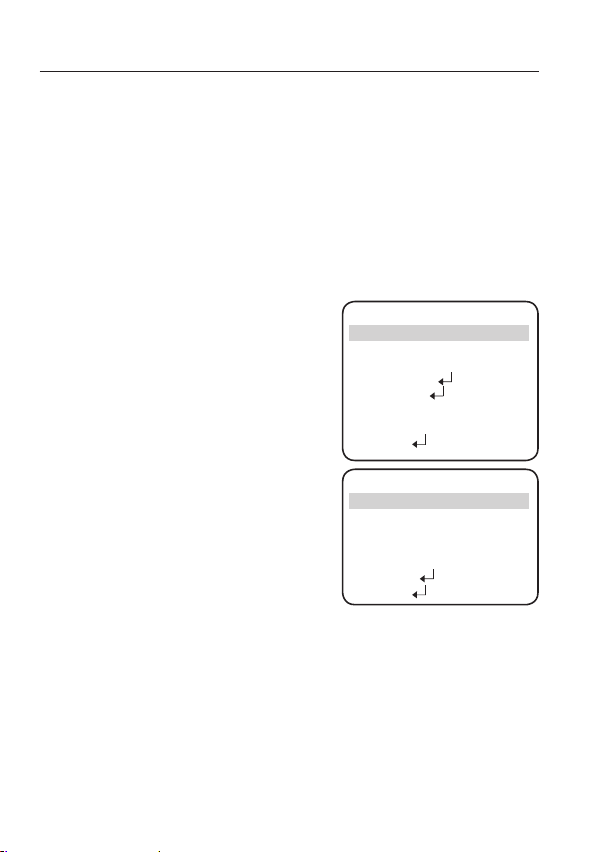
INTELLIGENCE:
MOTION : Select motion types to
-
OFF : Not being used.
DETECTION : Since the camera
-
TRACKING : Commands the camera to
-
ENCE :
▶
You can select up to 4 FENCE.
F
ODE : Determines whether to use
▶
M
YPE : Two types, line and area, of
▶
T
OUNT : Displays the number of times that an object enters or leaves a
▶
C
▶
F
ILL : Fill or remove color from the FENCE.
▶
P
OSITION : Defines the position and detection direction of a line or
1) LINE FENCE
S
-
- X POS / Y POS : Adjust the size and position of the selected line fence.
ommands the camera to motion-detect and trace an object.
C
detects motion without
any additional external
sensor, you can monitor
activity more efficient.
detect and trace a moving
object.
the fence selected in the
FENCE.
fences are available.
fenced area.
fenced area.
EL POS : Selects a position from POS1,POS2.
30_ setup
detect.
▶ 1.MOTION OFF
2.DETECT BOX ON
3.ALARM OUT OFF
4.DETECT AREA
5.MASK AREA
6.SENSITIVITY
7.DET.SIZE
8.RETURN
▶ 1.FENCE FENCE1
2.MODE OFF
3.TYPE LINE
4.COUNT OFF
5.FILL OFF
6.POSITION
7.RETURN
NTELLIGENCE
I
IIIIIIII
IIIIIIIIIII IIIIIIIIII
T
RACKING
III IIIIIIIIII
3
3
Page 31
English_31
●
SETUP
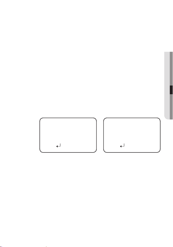
- DIRECTION
IR1 : Detects objects moving left to right on the fence line.
·
D
IR2 : Detects objects moving right to left on the fence line.
·
D
IR1/2 : Detects all objects moving crosswise on the fence line.
·
D
RETURN : Select this to save the POSITION menu settings and
return to the TRACKING menu.
2) AREA FENCE
- SEL POS : Selects a position from POS1 ~ POS4.
- X POS / Y POS : Adjust the size and position of the selected area fence.
- DIRECTION
·
IN : Detects objects entering the fenced area.
·
O
UT : Detects objects exiting the fenced area
·IN/OUT : Detects all objects entering and exiting the fenced area.
- RETURN : Select this to save the POSITION menu settings and return to
the TRACKING menu.
▶
RETURN : Select this to save the TRACKING menu settings and return to
the INTELLIGENCE menu.
1. SEL POS
2. X POS
3. Y POS
4. DIRECTION DIR1
5. RETURN
IIIIIIIIIIIIIIIIIIIII
IIIIIIIIIIIIIIIIIIIIIIIII
LINE FENCE
POS1
1. SEL POS
12
2. X POS
1
3. Y POS
4. DIRECTION IN
5. RETURN
FIXED/MOVED : Detects an object that emerges or disappears from the
or stays onscreen without movement
A detection (FIXED/MOVED) error may occur if :
M
· multiple motions occur continuously in random directions
· a fixed object moves in one position continuously
a second object screens the first moving object
·
DETECT BOX : Outlines an object on the scr
-
ALARM OUT : Releases a signal fr
-
movement matches a custom Motion Type.
camera when an object’s movement matches a custom
Motion Type.
een in a box when its
om the MD Output Terminal of the
AREA FENCE
POS1
IIIIIIIIIIIIIIIIIIIII
IIIIIIIIIIIIIIIIIIIIIIIII
.
12
s
creen,
1
Page 32
setup
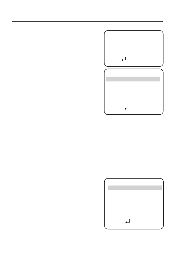
ETECT AREA : Defines the Motion
D
-
Detection area.
MASK AREA : Specify a detection
-
exception area to mask.
Select a mask area
number and specify the
size and position.
▶
A
REA : You can select up to 4 areas.
ODE : Determines whether to use the
▶
M
area selected in the AREA.
▶
T
OP / BOTTOM / LEFT / RIGHT :
Adjust the size and position of the
selected area.
▶
Select this to save the MASK
RETURN :
AREA menu settings and
the INTELLIGENCE
return to
menu.
SENSITIVITY : Set the sensitivity of the motion detection. When adjusting
-
the sensitivity, note that the lower the level means the higher
1. TOP
2. BOTTOM
3. LEFT
4. RIGHT
5. RETURN
▶1. AREA
2. MODE
3. TOP
4. BOTTOM
5. LEFT
6. RIGHT
7. RETURN
DETECT AREA
MASK AREA
IIIIIIIIIIIIIIIIIIIIIIIII
IIIIIIIIIIIIIIIIIIIII
IIIIIIIIIIIIIIIIIIIIIIIII
IIIIIIIIIIIIIIIIIIIII
AREA1
IIIIIIIIIIIIIIIIIIIIIIIII
IIIIIIIIIIIIIIIIIIIIIIII
IIIIIIIIIIIIIIIIIIIIIIIII
IIIIIIIIIIIIIIIIIIIIIIII
OFF
110
110
sensitivity.
DET. SIZE : Selects an object size to detect on the screen. When adjusting
-
the detection size, note that the higher the level means the bigger
detection size.
RETURN : Select this to save the INTELLIGENCE menu settings and return to
-
pRIVACy
1
2
-
AREA:
MODE :
-
the SPECIAL menu.
: Mask an area you want to hide on the screen,
When the SPECIAL menu screen is
displayed, press the Function Setup
switch so that the arrow indicates
‘PRIVACY’.
Set up the mode using the Function
Setup switch.
You can select up to 12 PRI
V
ACY
areas.
Determines whether to use
RIVACY AREA SETUP
P
▶ 1.AREA AREA1
2.MODE OFF
3.MASK COLOR GREEN
4.TRANSPARENCY OFF
5.SEL POS L_TOP
6.XPOS
7.YPOS
8.RETURN
I
I
IIIIIIIIIIIIIIIIIIII
IIIIIIIIIIIIIIIIIIII
the area selected in the AREA
SEL.
1
50
1
50
30
25
1
0
0
1
32_ setup
Page 33
English_33
●
SETUP
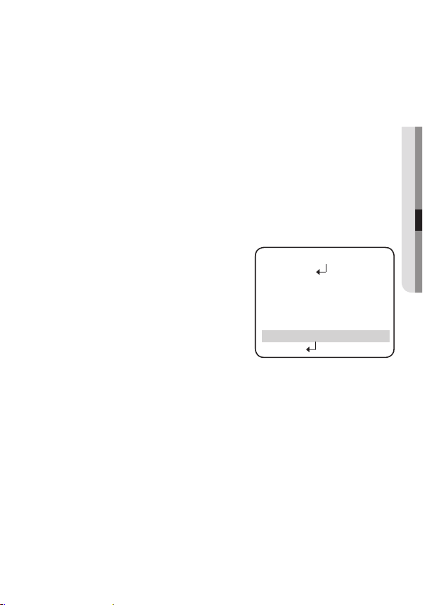
MASK COLOR : Determine
-
-
TRANSPARENCY :
SEL POS/XPOS/YPOS : Adjust the size and position of the selected area.
-
RETURN :
-
DI
S
This function mitigates any picture movement due to external factors such as wind.
M
PROFILE
-
BASIC : The most common envir
is set to meet.
-
DAY/NIGHT :
-
BACKLIGHT : It will be set automatically so you can distinguish the object from
-
ITS : It will be set automatically so you can easily check the traffic conditions.
-
INDOOR : It will be set automatically to help you take a picture in a regular
-
USER : Automatically configures the camera to your custom settings.
1)
2)
3)
4)
Select
SPECIAL menu.
(Digital Image Stabilizer) :
As the DIS function uses the digital zoom the camera's resolution will decrease.
DIS doesn’t operate when background illumination is too low.
DIS doesn’t operate when object pattern is monotonic as like sky or white wall.
elect a desired mode using the
S
:
Function Setup switch according
to the
picture
It will be set automatically
so it optimizes to the day
or night
respectively.
the background in a severe backlighting scene.
indoor lighting condition.
Select Custom for Simple Setup mode.
Configure the menu options to your custom settings.
The settings are automatically saved as Custom mode.
Profile user mode don't initialize when menu resets.
area color. You can select GREEN, RED, BLUE,
BLACK, WHITE and GRAY.
Adds or r
emoves transparency from the masking area.
this to save the PRIVACY menu settings and return to the
PECIAL
S
you want.
isplay
d
conditions,
onment
▶ 1.IMAGE ADJ
2.CAM TITLE OFF
3.SYNC INT
4.INTELLIGENCE OFF
5.PRIVACY OFF
6.DIS OFF
7.PROFILE BASIC
8.RETURN
Page 34

setup
I
n the PROFILE menu, you can configure the following camera settings at
*
ASIC DAY/NIGHTBACKLIGHTITS INDOOR USER
SHUTTER --- --- ---MANUAL(1/250)A.FLK -
AGC HIGH HIGH HIGH HIGH HIGH WHITE BAL ATW ATW ATW OUTDOOR INDOOR BACKLIGHT OFF OFF USER BLC OFF OFF -
SSNR3 ON ON ON ON ON -
DAY/NIGHT AUTO AUTO AUTO AUTO AUTO -
B
EXIT
S
elect a desired EXIT mode using the Function Setup switch depending on the camera
purpose.
SAVE : Save the current settings and exit the MAIN SETUP menu.
NOT SAVE : Do not save the current settings and exit the MAIN SETUP menu.
RESET: Resets the camera settings to the factory defaults.
Language and Monitor settings are not initialized.
once.
34_ setup
Page 35
troubleshooting
TROUBLESHOOTING
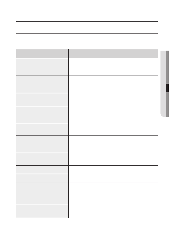
f you have trouble operating your camera, refer to the following table. If the guidelines do
I
not enable you to solve the problem, contact an authorized technician.
PROB
Nothing appears on the screen.
The image on the screen is dim.
he image on the screen is dark.
T
The camera is not working
properly, and the surface of the
camera is hot.
The DAY/NIGHT menu does not
work.
he SENS-UP function does not
T
work.
T
he INTELLIGENCE function does
not work.
olor is not correct.
C
he screen flickers continually.
T
W
not available:
T
he camera is out of focus.
SOLU
LEM
▶ Check that the power cord and line connection between the camera
and monitor are fixed properly.
C
heck that you have properly connected BNC cable to the camera.
▶
▶
Is the lens stained with dirt? Clean your lens with a soft, clean cloth.
heck the monitor and DVR settings.
▶
C
f the camera is exposed to very strong light, change the camera position.
▶
I
▶
djust the contrast feature of the monitor .
A
I
f you have an intermediate device, set the 75Ω / Hi-z properly.
▶
C
heck that you have properly connected the camera to an appropriate
▶
power source.
heck that AGC of EXPOSURE SETUP menu is ‘OFF’.
C
▶
heck that AGC of EXPOSURE SETUP menu is ‘OFF’.
▶ C
C
▶
heck that SHUTTER of EXPOSURE SETUP menu is ‘A.FLK’ or
‘MANUAL’.
▶
C
heck that INTELLIGENCE of menu is ‘OFF’.
heck the setting of WHITE BAL SETUP menu .
▶ C
heck that the camera is not pointing at the sun.
▶ C
hen coaxial communication is
▶M
recommended distance.
se the video amplifier equivalent to coaxitron if the
U
▶
recommended installation distance is exceeded.
▶C
heck that you have properly adjusted the zoom/focus
adjustment lever of lens.
TION
ake sure that the camera and monitor are installed within the
●
TROUBLESHOOTING
English_35
Page 36
specifications
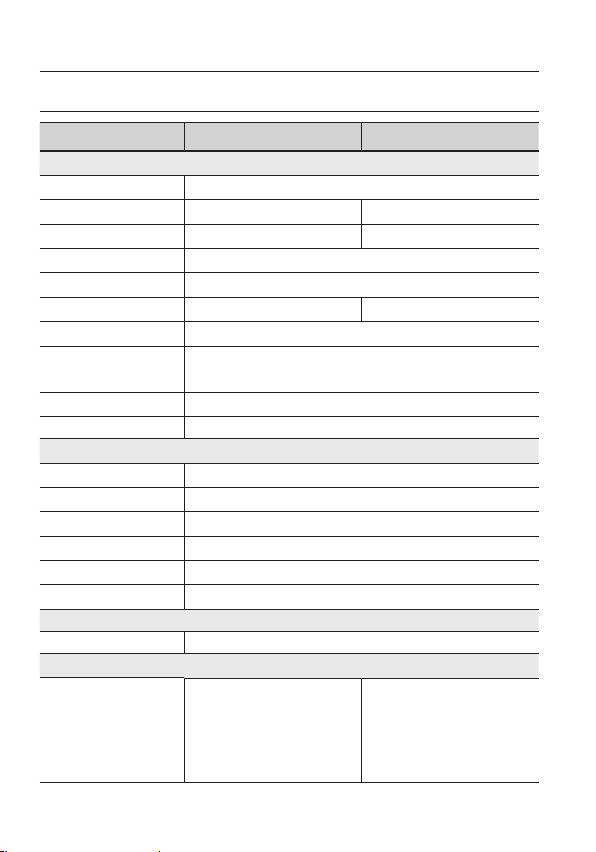
SPECIFICATIONS
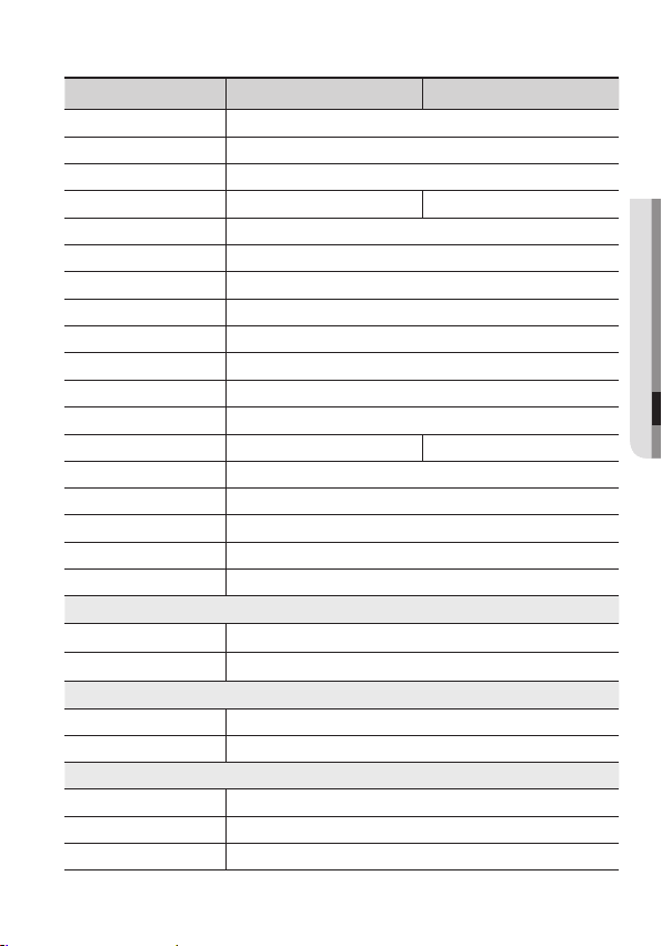
VIDEO
Imaging Device
Total Pixels
Effective Pixels
Scanning System
Synchronization
quency
Fre
Horizontal Resolution
Min. Illumination
S / N Ratio
Video
Output
Type
Lens
Focal Length(Zoom Ratio)
Max. Aperture Ratio
Angular Field of View
in. Object Distance
M
Lens Type
Mount Type
Pan / Tilt /Rotate
Pan/Tilt/Rotate Range
OPERA
n Screen Display
O
TIONA
L
1/3’’ Super HAD CCD ( Double Scan )
1028(H) x 508(V) 1028(H) x 596(V)
976(H) x 494(V) 976(H) x 582(V)
2 : 1 Interlace
Internal / Line Lock
H:15.734KHz / V:59.94Hz H:15.625KHz / V:50Hz
Color : 650 TV lines, B/W : 700 TV lines
COLOR : 0.1 Lux (50IRE, @F1.2), 0.0002Lux (SENS-UP, x512)
B/W : 0.01Lux (50IRE, @F1.2), 0.00002Lux (SENS-UP, x512)
52dB (AGC off, Weight on)
CVBS : 1.0 Vp-p / 75Ω composite
2.8 ~ 11mm (3.9x)
1:1.2(Wide) ~ 2.8(Tele)
H: 94.0°(Wide) ~ 26.0°(Tele) / V: 67.0°(Wide) ~ 20.0°(Tele)
0.2m
DC Auto Iris
Board Type
0°~352° / 0°~73° / 0°~348°
Multi-language Support by
Coaxial Cable
English, Japanese, Spanish, French,
Portuguese, Korean
SCV-3082 N SCV-3082 P
Multi-language Support by
Coaxial Cable
, Taiwanese
English, French, German, Spanish,
Italian, Chinese, Russian, Polish,
Czech, Romanian, Serbian, Swedish,
Danish, Turkish, Portuguese
36_ specifications
Page 37
Camera Title
Day & Night
Backlight Compensation
Wide Dynamic Range
Dynamic
Range (SSDR)
Digital Noise Reduction (SSNR
Ⅲ )
Digital Image Stabilization
Intelligent Video
Privacy Masking
Sens-up (Frame Integration)
Gain Control
White
Balance
Electronic Shutter Speed
Digital Zoom
Profile
ETC
Communication
Protocol
Off / On (Displayed 15 characters)
Auto (ICR) / EXTERNAL/ Color / B/W
Off/ USER BLC / HLC / WDR
128x (52dB) 160x (54dB)
Off / On
Off / On
Off / On
Yes
Off / On (12 Programmable zones)
2x ~ 512x
Off/ Low / High
ATW / Outdoor / Indoor / Manual / AWC (1,700K° ~ 11,000K°)
1/60 ~ 1/120,000 sec
Off / On (1x ~ 16x)
Basic, Day & Night, Backlight, ITS, Indoor, User
Virtual Progressive Scan, PIP, Reverse
Coaxial Control ( SPC-300 Compatible )
Coax: Pelco-C (Coaxitron)
ScV
-3082
n ScV
1/50 ~ 1/120,000 sec
Environmental
Operating Temperature / Humidity
-10°C ~ +55°C (+14°F ~ +131°F) / Less than 90% RH
Ingress Protection IP66
Electrical
Input Voltage
Power Consumption
AC 24V ± 10% , DC 12V±10%
Max. 3.6W
Mechanical
Color / Material
Dimension
Weight
※
This specification can be changed without notice for performance impr
Body: Ivory, ALDC12 / Dome Cover : PC
Ø137 x 106mm
721g
ovement of product.
-3082
p
English_37
●
●
●
TROUBLESHOOTING
SPECIFICA
TIONS
Page 38
specifications
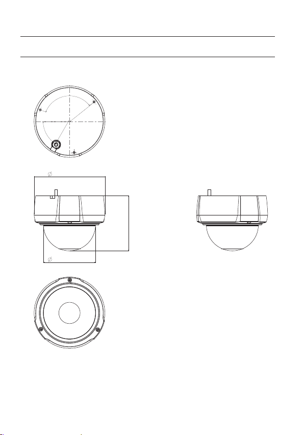
105.9 (4.17")
100.0 (3.94")
137.0 (5.39")
120°
60.3 (2.37")
51.5 (2.03")
60°
Unit : mm(Inches)
DIMENSION
38_ specifications
Page 39

MEMO
Page 40

SALES NETWORK
SAMSUNG TECHWIN CO., LTD.
Samsungtechwin R&D Center, 701, Sampyeong-dong, Bundang-gu, Seongnam-si, Gyeonggi-do, Korea, 463-400
TEL
: +82-70-7147-8740~60, FAX : +82-31-8018-3745
SAMSUNG TECHWIN AMERICA Inc.
100 Challenger Rd. Suite 700 Ridgefield Park, NJ 07660
Toll Free : +1-877-213-1222 Direct : +1-201-325-6920
Fax : +1-201-373-0124
www.samsungcctvusa.com
www.samsungtechwin.com
www.samsungsecurity.com
SAMSUNG TECHWIN EUROPE LTD.
Samsung House, 1000 Hillswood Drive, Hillswood Business Park
Chertsey, Surrey, UNITED KINGDOM KT16 OPS
TEL :
+44-1932-45-5300, FAX : +44-1932-45-5325
PT01-001038
A
 Loading...