

Samsung SCH-A310 Service Manual
SERVICE
PORTABLE CELLULAR
TELEPHONE
SCH-A310
Manual
PORTABLE CELLULAR TELEPHONE CONTENTS
1. General Introduction
2. Specification
3. Installation
4. NAM Programming
5. Product Support Tools
6. Circuit Description
7. Test Procedure
8. Trouble Shooting
9. Exploded Views and Parts List
10. Block Diagram
11. Electrical Parts List
12. PCB Diagrams
13. Circuit Diagrams

©Samsung Electronics Co.,Ltd. August. 2002
Pinted in Korea.
Code No.: GH68-03090A
BASIC.
ELECTRONICS

SAMSUNG Proprietary-Contents may change without notice
1-1
1. General Introduction
The SCH-A310 DBDM(Dual Band Dual Mode) phone functions as both analog phone working in AMPS
(Advanced Mobile Phone Service) mode and digital phone working in PCS (Personal Communication Service)
and GPS modes.
The following standards and minimum performance standards shall be met or exceeded by each subscriber
unit.
Air Interface
The Subscriber Unit shall be Dual mode and Dual band in compliance with ANSI J-STD-008 and TIA/EIA IS95A(Analog).
ANSI J-STD-008 : Personal Station-Base Station Compatibility Requirements for 1.8 to 2.0 GHz CDMA PCS.
ANSI J-STD-018 : Recommended Minimum Performance Requirements for 1.8 to 2.0 GHz CDMA Personal
Stations.
CDG Ref. Document #27 : High Rate Speech Service Option for Wideband Spread Spectrum System.
TIA/EIA IS-96A : Speech Service Option 1 Standard for Dual mode Wideband Spread Spectrum Cellular
Systems.
TIA/EIA IS-125 : Recommended Minimum Performance standards for Digital Cellular Wideband Spread
Spectrum Speech Service Option1.
TIA/EIA IS-126-A : Mobile Station Loop back Service Option standard.
TIA/EIA IS-95B : Mobile Station-Base Station Compatibility Standard for Dual-Mode Wideband Spread
Spectrum Cellular Systems;for the analog air interface.
TIA/EIA IS-98C : Recommended Minimum Performance Standard for Dual-Mode Wideband Spread PCS
Cellular Systems. Both Analog and CDMA sections apply.
TIA/EIA IS-801-1 : Position Determination Service standards for Dual Mode Spread Spectrum System.
CDMA Receiver/Transmitter Specifications and Requirements
The Subscriber Unit shall comply with ANSI J-STD-008 and meet or exceed TIA/EIA IS-98C. The Subscriber
Unit shall comply with Personal Station Class II.
Analog Receiver/Transmitter Specifications and Requirements
The Subscriber Unit shall comply with TIA/EIA IS-95B and meet or exceed TIA/EIA IS-95. The Subscriber Unit
shall comply with Mobile Station Power Class III (600 mW).

SAMSUNG Proprietary-Contents may change without notice
2-1
2. Specification
2-1 General
Item US PCS CDMA AMPS GPS
Tx Freq. range 1851.25~1908.75MHz 824.70~848.31MHz 824.04~848.97MHz -
Rx Freq. range 1931.25~1988.75MHz 869.70~893.31MHz 869.04~893.97MHz 1574~1576MHz
Channel Bandwidth 1.23MHz 1.23MHz 30KHz
Channel Spacing 50KHz 30KHz 30KHz -
Number of Channel 1200 20FA 832 -
Duplex Separation 80MHz 45MHz 45MHz -
Type of Emission 1M25F9W 1M25F9W 40K0F8W, 40K0F1D -
In/Output Impdance 50Ω 50Ω 50Ω -
Tx Intermediate
Frequency 263.6MHz 228.6MHz 228.6MHz -
Rx Intermediate
Frequency 183.6MHz 183.6MHz 183.6MHz -
1st(FTX+263.6MHz) 1st(FTX+228.6MHz) 1st(FTX+228.6MHz)
Tx Local Frequency 2nd(527.2MHz) 2nd(457.2MHz) 2nd(457.2MHz) -
1st(FRX+183.6MHz) 1st(FRX+183.6MHz) 1st(FRX+183.6MHz)
Rx Local Frequency 2nd(367.2MHz) 2nd(367.2MHz) 2nd(367.2MHz) -
TCXO Frequency 19.2MHz 19.68MHz 19.68MHz -
Freq. Stabillity (F
RX - 80 MHz) ± 150 Hz (FRX - 45 MHz) ± 300Hz ± 2.5ppm -
Operating
Temperature -30
o
C ~ +60 oC -30 oC ~ +60 oC -30 oC ~ +60 oC-
Supply Voltage 3.80V
Size and Weight STD : 113 * 47 * 22mm, 900mAh

SAMSUNG Proprietary-Contents may change without notice
2-2
Specification
2-2 1.9GHz CDMA(US PCS)
GENERAL
Frequency Range
. Transmitter : 1851.25 ~ 1908.75MHz
. Receiver : 1931.25 ~ 1988.75MHz
Channel Bandwidth : 1.23MHz
Channel Spacing : 50kHz
Number of Channels : 1200
Duplex Seperation : 80 MHz
Type of Emission : 1M25F9W
Input/Output Impedance : 50 ohms
Intermediate Freequency
. Transmitter : 263.6MHz
. Receiver : 183.6MHz
Local Frequency
. Transmitter : 1st(FTX +263.6MHz), 2nd(527.2MHz)
. Receiver : 1st(FRX +183.6MHz), 2nd(367.2MHz)
TCXO Frequency : 19.2MHz
Frequency Stability : (FRX-80MHz) +/- 150Hz
Operation Temperature : -30deg ±60deg
Supply Voltage : +3.8V

SAMSUNG Proprietary-Contents may change without notice
2-3
Specification
TRANSMITTER
Waveform Quality : 0.944 or more
Open Loop Power Control Range
. -25dBm : -60.5dBm ~ -41.5dBm
. -65dBm : -20.5dBm ~ +1.5dBm
. -104dBm : +15.0dBm ~ +25.5dBm
Minimum Tx Power Control : below -50dBm
Closed Loop Power Control Range : +/-24dB
Maximum RF Output Power : 25.5dBm
Occupied Bandwidth : 1.23MHz
Conducted Spurious Emission @1.25 MHz : -42dBc/30kHz
RECEIVER
Rx Sensitivity and Dynamic Range : -104dBm, FER=0.5% or less
: -25dBm, FER=0.5% or less
Conducted Spurious Emission
. 1930~1990 MHz : <-81dBm
. 1850~1910 MHz : <-61dBm
. All Other Frequencies : <-47dBm
Single Tone Desensitization : lower than 1 %
. Rx power level = -101dBm
. Tone power level = -30dBm
. Tone offset from carrier = +/-1.25 MHz
Intermodulation Spurious Response Attenuation : lower than 1 %
. Rx power = -101dBm
. Tone 1 power = -43dBm
. Tone 1 power = -43dBm
. Tone 1 offset from carrier = +/-1.25 MHz
. Tone 2 offset from carrier = +/-2.05 MHz

SAMSUNG Proprietary-Contents may change without notice
2-4
Specification
2-3 800MHz CDMA
GENERAL
Frequency Range
. Transmitter : 824.70 ~ 848.31MHz
. Receiver : 869.70 ~ 893.31MHz
Channel Bandwidth : 1.23MHz
Channel Spacing : 30kHz
Number of Channels : 20FA
Duplex Seperation : 45 MHz
Type of Emission : 1M25F9W
Input/Output Impedance : 50 ohms
Intermediate Freequency
. Transmitter : 228.6MHz
. Receiver : 183.6MHz
Local Frequency
. Transmitter : 1st(FTX +228.6MHz), 2nd(457.2MHz)
. Receiver : 1st(FRX +183.6MHz), 2nd(367.2MHz)
TCXO Frequency : 19.2MHz
Frequency Stability : (FRX-45MHz) +/- 300Hz
Operation Temperature : -30deg ~ 60deg
Supply Voltage : +3.8V
TRANSMITTER
Waveform Quality : 0.944 or more
Open Loop Power Control Range
. -25dBm : -57.5dBm ~ -38.5dBm
. -65dBm : -17.5dBm ~ +1.5dBm
. -104dBm : +18.0dBm ~ +30dBm

SAMSUNG Proprietary-Contents may change without notice
2-5
Specification
Minimum Tx Power Control : below -50dBm
Closed Loop Power Control Range : +/-24dB
Maximum RF Output Power : 26dBm
Occupied Bandwidth : 1.23MHz
Conducted Spurious Emission @900 KHz : -42dBc/30kHz
@1.25 MHz : -54dBc/30kHz
RECEIVER
Rx Sensitivity and Dynamic Range : -104dBm, FER=0.5% or less
: -25dBm, FER=0.5% or less
Conducted Spurious Emission
. 869~894 MHz : <-81dBm
. 824~849 MHz : <-61dBm
All Other Frequencies : <-47dBm
Single Tone Desensitization : lower than 1 %
. Rx power level = -101dBm
. Tone power level = -30dBm
. Tone offset from carrier = +/-900KHz
Intermodulation Spurious Response Attenuation : lower than 1 %
. Tone 1 offset from carrier = +/-900KHz
. Tone 2 offset from carrier = +/-1.700MHz
- Test 1, 2
Rx power = -101dBm
Tone 1 power = -43dBm
Tone 2 power = -43dBm
- Test 3, 4
Rx power = -90dBm
Tone 1 power = -32dBm
Tone 2 power = -32dBm
- Test 5, 6
Rx power = -79dBm
Tone 1 power = -21dBm
Tone 2 power = -21dBm

SAMSUNG Proprietary-Contents may change without notice
2-6
Specification
2-4 800MHz AMPS
GENERAL
Frequency Range
. Transmitter : 824.04°≠848.97 MHz
. Receiver : 869.04°≠893.97 MHz
Channel Spacing : 30kHz
Number of Channels : 832
Duplex Spacing : 45MHz
Frequency Stability : +/-2.5ppm(-30deg°≠ 60deg, -22°£F °≠140°£F)
Modulation/Demodulation
. Voice : FM
. Data : PM
Operating Temperature : -30deg°≠ 60deg, -22°£F °≠ 140°£F
Supply Voltate : 3.8V
TRANSMITTER
RF output power : 27dBm
Carrier ON/OFF conditions
. "ON" Condition : within +/-3dB of specification output(in 2 ms)
. "OFF" Condition : below -60dBm(in 2ms)
Compresssor
. Compression Rate : 2 : 1
. Attack Time : 3ms
. Recovery Time : 13.5ms
. Reference Input : input power level for producing a nominal +/-2.9kHz
: peak frequency deviation of transmitted carrier
Preamphasis : 6dB/OCT within 0.3 °≠ 3 kHz

SAMSUNG Proprietary-Contents may change without notice
2-7
Specification
Maximum Frequency Deviation
. F3 of G3 : +/-12 kHz
. Supervisory Audio Tone : +/-2 kHz(+/-10%)
. Signaling Tone : +/-8 kHz(+/-10%)
. Wideband Data : +/-8 kHz(+/-10%)
Post Deviation Limiter Filter
. 3.0 ~ 5.9 kHz : above 40 LOG(F/3000)dB
. 5.9 ~ 6.1 kHz : above 35dB
. 6.1 ~ 15 kHz : above 40 LOG(F/3000)dB
. Over 15 kHz : above 28 dB
Spectrum Noise Suppression
. For all modulation
fo +20 kHz °≠ fo + 45 kHz : above 26dB
. For modulation by voice and SAT
fo + 45 kHz : above 63dB+10LOG(PY)dB
. For modulation by WBD(without SAT) and ST(with SAT)
fo + 45 kHz ~ fo + 60 kHz : above 45 dB
fo + 60 kHz ~ fo + 90 kHz : above 65 dB
fo + 90 kHz ~ 2 fo : above 63 dB + 10 LOG(PY) dB
( where fo = carrier frequency
PY=mean output power in watts )
Harmonic and conducted Spurious Emissions : below 43 + 10 LOG(PY) dB
RECEIVER
De-emphasis : -6dB/OCT within 0.3 ~ 3 kHz
Expandor
. Expandor Rate : 1 : 2
. Attack time : within 3 ms
. Recovery Time : within 13.5 ms
. Reference input : output power level to a 1000Hz tone from a
carrier within +/-2.9 kHz peak frequency deviation
Sensitivity : 12 dB SINAD/-116dBm
Intermodulation Spurious Response Attenuation : above 65dB
RSSI Range : above 60dB
Protection Against Spurious Response Interference : above 60dB

SAMSUNG Proprietary-Contents may change without notice
2-8
Specification
In Band Conducted Spurious Emission
. Transmit Band : below -60 dBm
. Receive Band : below -80 dBm
Out of Band Conducted Spurious Emissions : below -47dBm
. Radiated Spurious Emission
Frequency Range : Maximum Allowable EIRP
25 ~ 70MHz : -45dBm
70 ~ 130MHz : -41dBm
130 ~ 174 MHz : -41 ~ -32dBm
174 ~ 260 MHz : -32 dBm
260 ~ 470 MHz : -32 ~ -26 dBm
470 ~ 1G MHz : -21 dBm
2-5 1500MHz GPS
GENERAL
Frequency Range : 1574~1576 MHz

SAMSUNG Proprietary-Contents may change without notice
2-9
Specification
IN IDLE MODE
IN CONVERSATION MODE
1 Sxxxxx : SID (System Identification) toggle
Nxxxxx : NID (Network Identification) toggle
2 SIx : Slot cycle index (lowest between the system
and the phone will be used)
1. SI0 : Slot Index 0
2. SI1 : Slot Index 1
3. SI2 : Slot Index 2
3 Handset Status : 0 - NO SVC
1 - Synchronization
2 - Paging (Idle)
3 - Reg. Access state
4 - Traffic Initialization
5 - Waiting for order
6 - Waiting for answer
7 - Conversation state
8 - Exit
4 T-xx : Tx adjust, Value ranges from -63~+63dB
5 Dxxx : Sector power in dBm
6 -xx : ec/lo
7 Pxxx : PN offset
8 CHxxxx : Channel number
9 TV : Tx vocoder rate (8 is full rate, 1 is 1/8th rate)
10 RV : Rx vocoder rate (8 is full rate, 1 is 1/8th rate)
11 xx : Walsh code used in traffic channel
12 System acquisition state
2-6 PCS Debug Display Information
To select debug display mode : Press [MENU] + [0] + [0], and press [0] + [4] + [0] + [7] + [9] + [3], and press [1].
Sxxxxx SIx x
T - xx Dxxx - xx
Pxxx CHxxxx
xx xx
1
4
7
6
8
5
12
2 3
TVx RVx xx x
T - xx Dxxx - xx
Pxxx CHxxxx
xx xx
9
3
12
10 11

SAMSUNG Proprietary-Contents may change without notice
2-10
Specification
1 SIDxxxxx : AMPS Home System ID
2 PWRx : Power Level 0 ~ 7
3 SATx : Supervisory Audio Tone code (0 ~ 2)
4 x (Using Frequency Band) : A Band or B Band
5 RSSIxxx : RSSI value
6 CHxxx : Channel number
7 Handset Status : 1 - Initialization state
2 - Idle state
3 - System Access state
4 - Voice channel state
8 System acquisition state
2-7 AMPS Debug Display Information
To select debug display mode : Press [MENU] + [0] + [0], and press [0] + [4] + [0] + [7] + [9] + [3], and press [1].
SIDxxxxx x x
PWRx RSSIxxx
SATx CHxxxx
xx xx
1
2
3
5
6
8
7 4
3. Installation
3-1 Installing the Battery
SAMSUNG Proprietary-Contents may change without notice
3-1
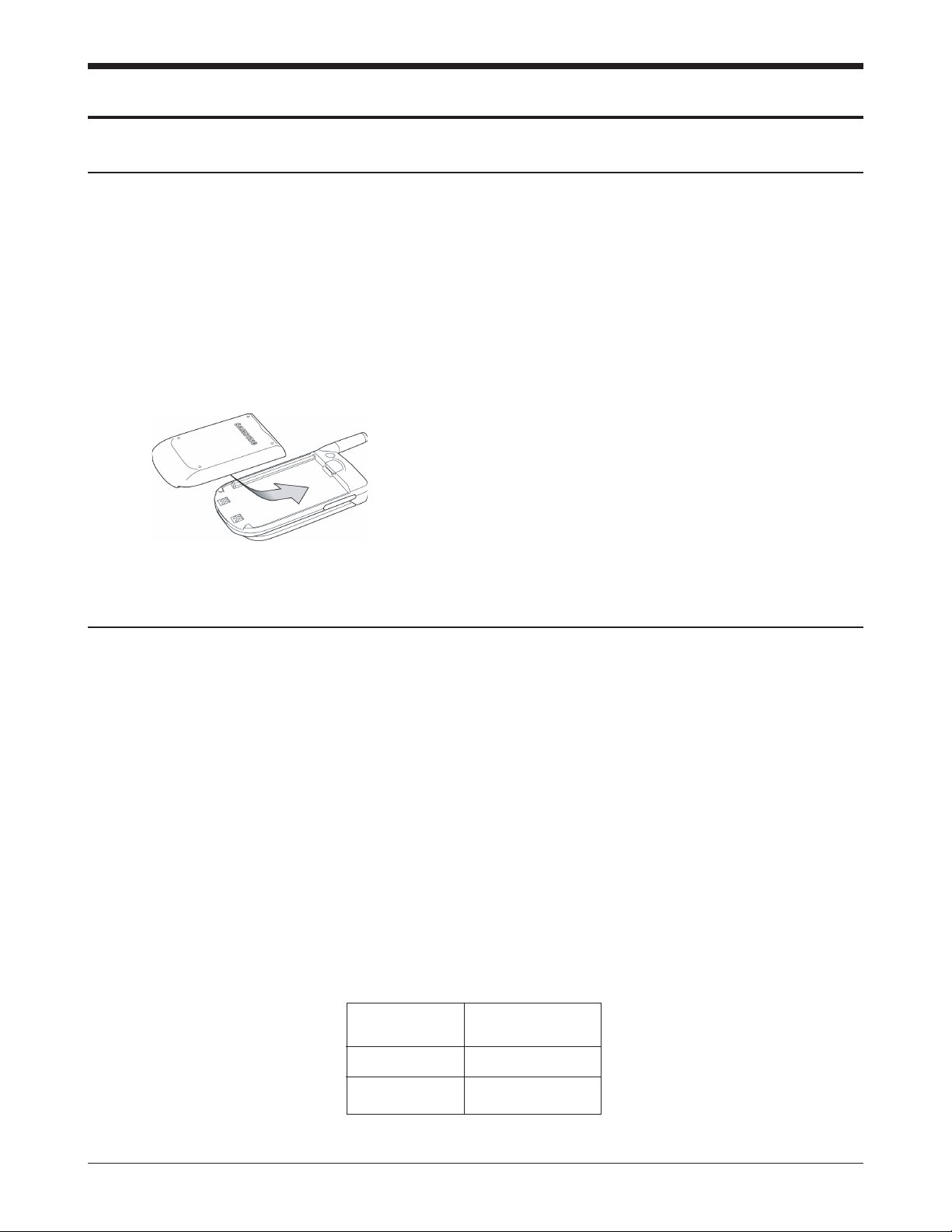
To attach the battery to your phone:
1. Gently place the battery into the provided slots on
the underside of the phone.
2. Slide the top end of the battery up (The top end of
the battery displays the word Samsung in raised
letters.) until you hear it click into place.
To remove the battery from your phone:
1. Turn the phone off (by pressing and holding
[PWR] until the closing animation begins).
2. On the back side of the phone, hold the button
down and push the battery toward the bottom
edge of the phone. The battery will then lift or fall
away from the phone.
3-2 Using the travel adaptor
1. With the battery in position in the phone, attach
the cord from the travel adaptor by plugging it
into the adaptor outlet at the bottom of the phone.
2. Connect the adaptor to a standard 110/220 free
volt AC wall outlet. The battery will begin
charging immediately, and the LED (located at the
top of your phone) will light and remain red
while the battery icon animates, the icon will
remain animated, even if the phone is turned off
during charging.
3. The LED indicates the status of the battery being
charged.
•Red indicates that the battery is charging.
•Green indicates that the battery is fully charged.
•Yellow indicates (1) the battery is not seated
correctly in the phone, (2) the adaptor is not
plugged in correctly, or (3) the battery is
inoperable. Please check the adaptor and/or
battery.
4. You can make a phone call when the phone is
plugged into the travel adaptor. The adaptor will
continue to charge the battery even when you are
making the call.
Specifications using DTC (Desk Top Charger)
Battery Type Standard Battery
(Li-ion, 900mAh)
Charging Time 2:30 hours
SEC Code GH43-00545A

SAMSUNG Proprietary-Contents may change without notice
3-2
Installation
3-3 For Mobile Mount
3-3-1 Cradle
1. Choose a location where it is easy to reach and
does not interfere with the driver’s safe
operation of the car.
2. Separate the two halves of the clamshell by
removing the two large slotted screws. See the
figure 3-2.
3. Drill holes and mount the lower half of the
clamshell by using the screws.
4. Place the cradle onto the remaining half of the
clamshell and assemble them by using the
screws.
5. Reassemble the two halves of the clamshell
together. Adjust the mounting angle and tighten
the two slotted screws.
Figure 3-2 Cradle Installation
CLAM SHELL
MOUNT UPPER
CLAM SHELL
MOUNT LOWER
CRADLE
FIXED SCREW
CAR
32
32
SCH-A310
MAIN PHONE
HANDS
FREE BOX

SAMSUNG Proprietary-Contents may change without notice
3-3
Installation
3-3-2 Hands-Free Box
1. Drill holes in a proper location for the handsfree box, attach the mounting bracket by using
the screws. See the figure 3-3.
2. Install the hands-free box into the bracket.
3-3-3 Speaker
1. Install the speaker into the appropriate position.
3-3-4 Hands-Free Microphone
1. It is recommended to install the microphone
where it is 30-45 cm (12-18”) away from the
driver. Choose the location where is least
susceptible to interference caused by external
noise sources, ie, adjacent windows, car audio
speakers, etc. Normal place is the sun visor.
2. Once the microphone has been correctly
positioned, connect the microphone wire to the
MIC jack on the hands-free box.
Figure 3-3 Hands-Free Box Installation
MOUNTING BRACKET
CAR
40
55

3-3-5 Cables
1. Connect the cradle and the hands-free box with
the data cable.
2. Connect the red wire to the battery (+) terminal,
black wire to the vehicle chassis, brown wire to
the Car Audio Mute port and orange wire to the
ignition port in the key box of vehicle or battery
(+) terminal.
3. Connect the other end of the power cable to the
PWR jack of the hands-free box.
Notes:
•It is recommended to connect the power cable
directly to the battery to avoid power noise.
•Make sure the connection between the battery (-)
terminal and vehicle chassis is made correctly.
•Make sure the fuse having a proper capacity is
used on the power cable.
•Make sure the cables do not pass over any sharp
metal edge that may damage it.
SAMSUNG Proprietary-Contents may change without notice
3-4
Installation

SAMSUNG Proprietary-Contents may change without notice
4-1
4. NAM Programming
4-1 NAM programming
Programming of all NAM parameters, e.g. Service Security Code, MCC, MNC, MIN#, CDMA Channel#,
vocoder rate, MOB_TERM, SID, SID/NID pairs, Slot Cycle Index, etc.
1) Press “Menu 6, ∗” Enter SPC Code “000000” Use Right navigation key to select items to program.
2) You can select MORE (Menu) when “Basic NAM 1 programming is complete.” displays. Select if you want
to program more detailed items than shown in basic NAM programming. Press OK to save or Right
navigation key to proceed to next item.
-> MORE programming not a required for NAM programming.
3) To toggle between settings, e.g. Home SID/NID pairs or selecting between Yes/No, use the Up/Down
navigation key:
A. For changing Home SID/NID pairs, select from SID/NID pair numbers 01 to 20 by pressing Up
navigation key Press [edit] by pressing Menu key to change setting Press OK key to save setting.
B. For changing Forn SID or NID Registration, Home Sys. Registration, etc. press Up/Down navigation
key to select between Yes or No. Press OK key to save setting.
4) Press End Key to save & exit NAM programming.
4-2 Field Debug Screen and Test Calls
1) Press “Menu 0, ∗” Enter “000000” ;
1 ; Debug Screen
2 : Test Calls:
Markov New 8K, Markov New 13K, Loop Back 8K, Loopback 13K,
TDSO Call Simple, TDSO Full
2) Repeat above 1) to exit Debug screen
4-3 A-Key programming via Keypad
1) Press “Menu 6, ∗” Enter SPC Code “000000” Menu (Soft key) - then you will see “Press[AKEY] to continue
AKEY: “ Menu ([AKEY] ) Enter the 20-digit AKEY. Press “OK” Key to save value.

SAMSUNG Proprietary-Contents may change without notice
4-2
NAM Programming
4-4 Channel Preset mode
1) Press “4 7 ∗ 6 8 # 1 3 5 8 0” in idle mode 001 021 and then:
for PRL based system selection enter 00000 and save(OK key).
for AMPS ; 10000 for System A, 10001 for System B
for 800MHz CDMA ; 2XXXX (XXXX is CDMA channel number)
for 1.9GHz CDMA ; 3XXXX (XXXX is PCS Channel number)
2) Press OK or “∗ Shift” key to save mode/channel value.
3) When “Saved” displays briefly, press 002 to exit test mode programming
4-5 MRU Table Review and Reset
You can review upto 12 system and channel information from the MRU Table, or reset the entire MRU table as
follows:
1) Press “4 7 ∗ 6 8 # 1 3 5 8 0” in idle mode 001 031 (MRU2 TABLE), then:
“MRU00: yzxxxx” where “y” is Mode definition(1; Analog, 2:Digital),
“z” is Band Class (0; 800MHz, 1; 1.9GHz), and
“xxxx” is Channel number, or A or B band for AMPS.
“MRU00” to “MRU11”, total of 12 MRU entries available.
Ex) for CDMA 800MHz Channel 384 in 4th MRU entry order:
“MRU03: 200384” will display.
Ex) for PCS 1.9GHz Channel 150 in 7th MRU entry order:
“MRU06: 210150” will display.
Ex) for AMPS A-band in1st MRU entry order: “MRU00: 100000” will display.
for AMPS B-band in 2nd entry order: “MRU01: 100001” will display.
2) To toggle up and down the MRU entry numbers from 00 to 11, press Up or Down navigation key.
3) To reset entire MRU table (00 to 11), enter “000000” at “MRU00:” setting, then press OK or “∗ Shift” key.
4) When “Saved” displays briefly, press 002 to exit test mode programming

SAMSUNG Proprietary-Contents may change without notice
4-3
NAM Programming
4-6 Using DM Data (over-the-air messaging)
1) Press “Menu, 0, ∗” in idle mode Enter SPC Code “000000” Press “5” Port Map.
2) Select “U1:DM&DL, U2:NULL” for Samsung DM, or “U1:QC_DM, U2:NULL” for Qualcomm DM.
3) If “U1:QC_DM, U2:NULL” is selected, the Qualcomm DM COM port must be set to COM1 and
Baud rate to 38400.
(Note) U1: UART 1, U2: UART 2
DM& DL : DM and Download Mode
( Please set this mode when you take a logging.)
DS & HF : Handsfree Mode
QC_DM : Qualcomm DM Mode
4-7 Making Markov Test Calls
1) Originate a desired phone number in normal idle mode to create an outgoing call list.
2) Press “Menu 0, ∗” Enter SPC Code “000000” Press “2”
3) Make a Markov Call by selecting “Markov New 13k”.
4) The MS will originate the Markov call using the first entry in the outgoing call list.
5) If the outgoing call list is empty(no outgoing call made), the MS will originate to a default number of
'1234567'.
4-8 Fax & Data Calls:
1) Press “Menu 8, 7” in idle mode
2) Toggle among “Data/Fax Off”, “Fax for Next Call”, “Fax until Powered Off”, “Modem for Next Call”,
“Modem until Powered Off” using Navigation Up/Down Key.
3) If “Fax/Data Off” is selected, phone will display “No incoming data/fax calls can be received”.
4) If “Fax for Next Call” is selected, phone will display “Waiting for fax call (no voice) for 10min”.
5) If “Fax until Powered Off” is selected, phone will display “No incomming voice calls can be received”.
6) If “Modem for Next Call” is selected, phone will display “Waiting for data call (no voice) for 10min”.
7) If “Modem until Powered Off” is selected, phone will display “No incomming voice calls can be received”.

SAMSUNG Proprietary-Contents may change without notice
4-4
NAM Programming
8) Text notification of “∗Data Only∗” or “∗Fax Only∗“ will be displayed.
9) Outgoing Fax/Data Calls: Using a computing device application software, originate
calls in any state in idle mode. (For details, refer to the Draft User Manual enclosed)
4-9 8K/13K Mobile Originated SMS
1) Set Vocoder Rate(8K EVRC, 13K) via NAM Programming
Enter [Menu], 9, ∗, “000000”, “4: Voice SO “
Then Choose desired vocoder rate from “Default”, “EVRC Call”, and “13k Call”.
Press OK key to save setting, then press END key to exit.
2) In idle mode, press “OK” Key to select from “1: New Messages”, “2: Voice”, “3: Text Inbox”, or
“4: Text Outbox”.
3) Select “1: New Messages” for Mobile Originated SMS messaging.
4) Press Destination mobile number or e-mail address thru the keypad then press OK key.
5) Enter text message at “2:Message” then press OK key to store. Press Menu key to select from ABC,
Number, T-9 Word, or Symbol mode.
6) Enter Call back number at “3:Call Back” then press OK key to store.
7) At “4: Options”, scroll using Up/Down navigation key, and select from options using Left/Right navigation
key for the “Priority” level, “Validity” Period, “Send Later” option, “Delivery Ack” On or Off,
or “Save Message” option.
8) At “5: Action”, press SEND key to transmit message, OK key to save message to Filed folder (not
implemented yet), “C” key to cancel MO messaging, or END key to quit.
9) If Save Message is set to “Auto Save”, the sent message is stored in the Txt Outbox.
4-10 Voice Privacy
1) In idle mode, press “Menu, 0” Enter “WXYZ” (where WXYZ is the last 4 digits of
the MIN number) Press “8” (Voice Privacy) Select from “standard” or
“enhanced” using the Up/Down navigation key down then press OK key to save value.
2) In conversation mode, press “Menu, 8”
Select from “standard” or “enhanced” using the Up/Down navigation key down
then press OK key to save value.

SAMSUNG Proprietary-Contents may change without notice
4-5
NAM Programming
4-11 Phone.com Browser IP Address & Port, Linger Timer Setting
1) IP Address
- Press “Menu, 3, 0” Enter “WXYZ” (where WXYZ is the last 4 digits of the MIN#)
- Press “1: Gateway”, then select “1: Address” for IP Address setting change. Select
from Address 1, 2, or 3, then scroll between IP “A”, “B”, or “C” using navigation key.
- Press OK key to access IP “A”, “B”, or “C”, enter new IP setting, then press OK key to store.
2) Port
- Press “Menu, 3, 0” Enter “WXYZ” (where WXYZ is the last 4 digits of the MIN#)
- Press “1: Gateway”, then select “2: Port” for port number setting change. Select from
Port 1, 2, or 3 for IP Address 1, 2, or 3, then select from Port A, Port B, or Port C.
- Press OK key to access Port A, B, or C, enter new Port number, then press OK key to store.
3) Linger Timer
- Press “Menu, 3, 0” Enter “WXYZ” (where WXYZ is the last 4 digits of the MIN#)
- Press “2: LingerTime”, then press [OK/Message] once.
- Enter the Default Linger Timer value ranging from 0 to 180 seconds, then press
[OK/Message] to save setting.
4-12 Auto Answer
1) Press “Menu, 8, 2” for Auto Answer.
2) Toggle using the navigation keys between, Off, after 1 ring, after 3 rings, and after 5 rings.
3)Press [OK/Message] to save setting. The mobile will automatically answer the incoming call after
the preset number of ring tones. (Useful feature for automatic equipment testing)

5. Product Support Tools
5-1 General
IMPORTANT INFORMATION
Purpose
The Product Support Tool (PST) offers you the ability to interface with the SAMSUNG DBDM telephone using
a PC. With this tool you can program the phones network system requirements and functionality, swap phone
data, and download software upgrades. This document supports UniPST version x.xx.
NOTE: This software must be executed in the Windows95/98 mode.
EQUIPMENT REQUIRED
Make sure you have the following equipment setup:
1. Minimum PC configuration: 586 CPU, 16MB RAM, Windows95/98, 5MB of disk space free for software
upgrade.
2. PST Software with appropriate cable (DM Cable for SAMSUNG DBDM phone).
3. Serial Port (16550 Serial Interface Card).
4. Power Supply (3.8 V) or Battery.
INSTALLATION
Software
1.Insert the PST floppy disk into drive (A:\).
2.Create an appropriate directory on the C:\ drive for PST software, Execute Setup.exe file,
The installation program creates folder and task bar on the windows95/98 start bar.
SAMSUNG DBDM Phone
The serial port should be configured to COM1 or COM2.
Use the following procedure to connect the phone, cable, and PC .
Plug the female end of the DM Cable into the 16550 card.
Pull the black rubber connector away from the socket at the base of the phone.
Plug the special connector on the cable into the socket at the base of the phone.
SAMSUNG Proprietary-Contents may change without notice
5-1
PC
Phone
DB Cable
(Parts No.:GH39-30525A)

SAMSUNG Proprietary-Contents may change without notice
5-2
Product Support Tools
5-2. PST (Product Support Tool)
5-2-1 Getting Started
MAIN MENU SCREEN
1. At the Windows95/98, Double Click “UniPst.exe”.
2. The Main Menu Screen will be displayed.
The Main Menu Screen shows the basic tasks that are available.
CAUTION: DO NOT attempt to program phone with a low battery.
PST SETUP
UniPst supports SAMSUNG DBDM portable telephone. You can select serial port COM1 or COM2.
5-2-2 Operation Procedure
Service Programming
The Service Programming screens enable you to set and change the service activation parameters of the
phones. These items can be changed individually or as a group via the “Edit Items” Property Sheet of the PST.
There are several pages on the Service Programming Property Sheet (See below Figure).
Read Data from File
Click “open” icon to select the name of a file whose extension is “mmc”. The values will be read from the
named file, and will initialize the parameter values seen on the Service programming screen
Read Data from Phone
Click Read from the Phone icon to upload the current programmable parameters of the phone. The values are
read from the phone, so the phone must have the power ON and be properly connected to the PST.
NOTE: To actually view the data you need to go to the Edit Items screens.
Edit Items
Click this icon to edit Number Assignment Module (NAM) items or UI items.
There are two types of screens:
1. Parameters associated with a particular Number Assignment Module (NAM)
2. UI items settings
Phone Book
Click this icon to edit Phone Book.
While you edit cell, you can use <Enter> and < UP , DOWN,LEFT,LIGHT Arrow> and <SPACE> key. If you
want to edit phone number or name , you must move rectangle box to cell where you want to edit , Write it
down . if <UP and DOWN Arrow> key is pressed, the cursor moves to next cell or previous cell.

SAMSUNG Proprietary-Contents may change without notice
5-3
Product Support Tools
Save Data to File
Click this icon to save the current parameters to a file. Once you enter a filename, Click <OK> button to write
all current parameters to that file. This way the same information can be downloaded into multiple phones.
Write to Phone
Click this icon to write the selected parameter values to the phone. Writing the selected values to the phone
may take up to a minute.
If there are dependencies in a field you can make all the changes in the proper fields and download the
information all together.
If you intend to use this “Write to Phone” feature, it is recommended that you do a “Read Data from Phone”
first, and then make the changes, so that nothing gets inadvertently overwritten.
NOTE: DO NOT TOUCH THE PHONE WHILE WRITING IS IN PROGRESS.
Software Download and Upgrade Screen
To begin a software upgrade or download, perform the following steps:
1. From the main menu screen choose DOWNLOAD MODE?
Click open icon to choose a BIN file of the new software to be loaded. Choose the appropriate BIN file, then
Click <Open> (see below figure).
2. Click Download? to begin downloading the file. You will notice various messages and a progress bar that
informs the user what percentage of the downloading has already occurred.
3. Click Mode Select box, then Select SERVICE MODE?to return to the Service Mode Screen.
NOTE: DO NOT POWER OFF WHILE THE PHONE IS BEING DOWNLOADED!

6. Circuit Description
6-1 Logic Section
SAMSUNG Proprietary-Contents may change without notice
6-1
6-1-1 Power Supply
To power on the phone, Pressing the PWR key with
the battery installed will short the V_BAT and
ON_SW signal. The V_DC, which is connected with
V_BAT, will be turned on simultaneously, The V_PD
and V_IF LDOs outputs of Regulator(U201, U322)
are turned on assuming V_BAT is greater than
2.85V.
Pressing the PWR key( )of the keypad for a few
seconds, The V_BAT voltage is applied to the
ON_SW, the ON_SW signal will transition high
when the PWR_HOLD signal is high.
The low state ONO\signal will be detected by the
MSM, when PWR_HOLD signal is high, to set the
PWR_HOLD signal low and power off the phone.
Once the PWR_HOLD signal is low all the LDOs
output of the Regulator(U201, U322)will be
powered off after typically 60ms delay and all the
logic of the PMIC will be reset to the shutdown
condition.
The V_PD output voltage of Regulator(U201) is
connected with V_MEM(used in memory),
V_LCD(used in LCD), V_MSMD(used in the digital
parts of MSM).
6-1-2 Inner Charging Circuit Part
The most important function of the charger shall be
done in the LTC1734(U240).
When the phone attached a battery is connected
with travel charging adapter, the inner charging
circuit of the LTC1734(U240) will charge by the
constant fast charge current.
When battery reaches regulation voltage of 4.2V
(default charging voltage for Li+mode), the charge
current drops quickly to 0mA by the programmed
data of the LTC1734 controlled from the MSM.
-Input voltage range : 4.75~8V
-Charging Temperature :0°C~40°C
-Charging Method : Constant Voltage/Current
-Charging Current : Max 550mA
-Charging Time : Standard (550mAh) 1.5 ~ 2 Hrs
Extended (900mAh) 3 ~ 3.5 Hrs
-Charging Mode : 1. Charging - RED Lamp
2. Completion -GREEN Lamp
-Charging Battery Regulation Voltage
1. Min 4.158V, Typical 4.2V, Max 4.242V
(at T
A : 0°C to +85°C)
2. Min 4.137V, Typical 4.2V, Max 4.263V
(at T
A : -40°C to +85°C)
-Over Battery Protection Voltage : Typical 5.2V
Universal Serial Bus Interface(U250)
SCH-A310 supports a Universal Serial Bus(USB)
interface, by the MSM 5100, to provide an efficient
interconnection between the mobile phone and a
Personal Computer(PC).
The MSM 5100's USB interface is designed to
comply with the Universal Serial Bus Specification,
Revision 1.1.
The USB interface of SCH-A310 and can be used to
transfer over-the-air data, or voice PCM samples
between the mobile phone and the USB host.
An external USB transceiver(U250) and 48MHz
crystal oscillator(OSC110) are required to implement
the USB interface.
END/

SAMSUNG Proprietary-Contents may change without notice
6-2
Circuit Description
6-1-3 Logic Part
The logic part consists of MSM, FROM, SRAM,
EEPROM, LCD and other input and output
peripherals.
MOBILE SYSTEM MODEM(U100:MSM5100)
The MSM5100 is designed to the IS-2000 standard
and enables up to a doubling of overall IS-95A/B
voice capacity and new, higher-data rate services.
The MSM5100 can support 153.6 kilobits per
second(kbps), providing manufacturers worldwide
ability to develop consumer products that provide
voice, high-speed data and video over wireless
networks. The MSM5100 chipset and system
software can support the phase1 1°øMC of the 3G
CDMA Multi Carrier IS-2000 standard, Release 0.
The MSM5100 device is available in the same 208pin FBGA production package allowing significant
reuse of existing MSM3100 chipset designs. The
MSM5100 integrates functions that support a trimode CDMA/FM subscriber unit. Subsystems
within the MSM5100 device include a CDMA
processor, a Digital FM(DFM) processor, a QDSP for
voice compression, an ARM7TDMI microprocessor.
Also integrated in the MSM5100 device are analog
functions such as an audio voice codec, PLL,
transmit DACS, ADCS, memories, USB controller,
peripheral interfaces, and an enhanced clock. It is
one of the most important components of the
CDMA cellular phone. The interface circuitry
consists of reset circuit, address bus (A0-A21), data
bus(D0-D15), and memory controls. The TCXO
clock of 19.68Mhz is used as the clock of SCH-A310
model.
FLASH ROM AND STATIC RAM (U120)
One 32MBIT Flash ROMs and 8MBIT Flash
ROM(U120) is used to store the cellular phone's
executable program and necessary data files and a
temporary data space to store the internal flag
informations, call processing data, timer data, and
other temporary data.
EEPROM(U190)
A 256KBIT EEPROM(U190) is used to store ESN,
NAM information, telephone directory, SMS
messages and other important information of the
phone.
KEYPAD
A key pad is used for the user interface function.
For key recognition, key matrix is operated by using
signals SCAN0-5 and KEY0-3 of the MSM.
LCD MODULE
The LCD module is a 128 X 128 dots graphic LCD
with one line of ICONS. Watch LCD is a 96 X 32
dots graphic LCD. The LCD contains a controller
which will display the information by 8-bit data
from the MSM. An external backlight circuitry is
used for easy operation in the dark.

6-1-4 RF Interface Part
CDMA, FM DATA INTERFACE
•I_OUT, I_OUT_N, Q_OUT, Q_OUT_N: TX analog
signal used during both CDMA and FM mode.
•C_RX_IDATA0-3 and C_RX_QDATA0-3: RX data
bus used during CDMA mode.
•FM_RX_IDATA and FM_RX_QDATA: RX data bus
used during FM mode.
CLOCK
TCXO_CLK: Reference clock used for generation of
CHIPX8. OSC141 : 32.768KHz sleep crystal. Clock
used during SLEEP.
ADC INTERFACE
Eight HK ADC are internally placed in the MSM.
These ADCs are used to read battery voltage,
battery typeand temperature.
RF INTERFACE
TX: TX_AGC_ADJ port is used to control the TX
power level and PA_ON signal is used to
control the power amplifier.
RX: RX_AGC_ADJ port is used to control the RX
gain and TRK_LO_ADJ is used to compensate
the TCXO module.
6-1-5 Audio Part
Internal CODEC in the MSM contains software
controlled amplifier for both the receiving and
transmitting sections. Also, the vocoding schemes
used will be 13kbps QCELP or 8K EVRC. Both
QCELP and EVRC vocoding are performed by the
MSM.
DIGITAL FM BLOCK
The digital FM processor is included in the Mobile
Station Modem(MSM) and brief descriptions of
each block are as follows :
FM TRANSMIT PROCESSOR
Pre-Emphasis Circuit
This part features +6dB/oct to reduce signal loss
and noise in Tx path.
Compressor
The compressor features 2:1 level compressor to
reduce signal loss and noise in Tx path. The zero
crossing level of the compressor is ±2.9 kHz/dev,
attack time is 3mS, and release time is 13.5mS.
Limiter
The limiter performs to cut ±0.53 Vp-p or higher
audio signal level so that the FM frequency
deviation is not over ±12 kHz/dev. The function is
used to avoid confusion over phone line. LPF is
used to reduce a specific high frequency of limited
signal.
SAMSUNG Proprietary-Contents may change without notice
6-3
Circuit Description
 Loading...