

Samsung SCH-611 Service Manual
SERVICE
CDMA Cellular Phone
SCH-611
Manual
CDMA Cellular Phone CONTENTS
1. General Introduction
2. Specification
3. Installation
4. NAM Programming
5. Product Support Tools
6. Troubleshooting
7. Exploded view and its Part List
8. Electrical Parts List
9. Block diagram
10. PCB diagrams
11. Circuit diagrams

©Samsung Electronics Co.,Ltd. Oct. 99
Printed in Korea.
Code No.: GH68-00668A
BASIC.
ELECTRONICS

1. General Description
The SCH-611 cellular phone functions as digital cellular phone working in CDMA(Code Division Multiple
Access) mode.
CDMA type digital mode applies DSSS (Direct Sequential Spread Spectrum) mode which first came to be used
in the military. The DSSS reduces channel cross talk and allow to use one frequency channel by multiple users
in the same specific area, resulting in increase of channel capacity to about ten times compared to that of analog
mode currently used.
Soft/Softer Handoff, Hard Handoff, and Dynamic RF Power Control technologies are combined into this phone
to reduce the call drop while usage.
CDMA digital cellular network consists of MSO (Mobile Switching Office), BSC (Base Station Controller),
BTS(Base Station Transmission System), and MS (Mobile Station). MS meets the specifications of the below:
• IS-95A : Mobile Station-Base Station Compatibility Standard for Dual-Mode Wideband Spread Spectrum
Cellular System
• IS-96A : Speech Service Option 1 Standard for Dual-Mode Wideband Spread Spectrum Cellular Systems
• IS-98A : Standards for Dual-Mode Wideband Spread Spectrum Cellular Mobile Station
• IS-126 : Mobile Station Loopback Service Options Standard
SAMSUNG Proprietary-Contents may change without notice
1-1
SAMSUNG Proprietary-Contents may change without notice
2-1
2. Specification
2-1 General
Frequency Range Digital Mode
Transmitter : 824 ~ 849 MHz
Receiver : 869 ~ 894 MHz
Channel Spacing : 1.23 MHz
Number of Channels : 20 FA
Duplex Spacing : 45 MHz
Frequency Stability : ±2.5 ppm (-30˚C ~ +60˚C, -4˚F ~ +140˚F)
Operating Temperature : -30˚C~+60˚C (-4˚F ~ +140˚F)
Operating Voltage
HHP : 3.6V DC (±10%)
Hands-free : 13.7V DC (±10%)
Operating Time
Digital Mode
Item Size Weight (g)
including slim battery 105 x 45 x 18 89
including standard battery 105 x 45 x 21 120
including extended battery 105 x 45 x 24 138
Item Standby Time Talk Time
slim battery up to 40 hours up to 80 hours
standard battery up to 75 hours up to 150 hours
extended battery up to 120 hours up to 240 hours

SAMSUNG Proprietary-Contents may change without notice
2-2
Specification
2-2 Digital Mode
Waveform Quality 0.944 or more
Time Reference ±1uS or less
Rx Sensitivity and Dynamic Range -104 dBm, FER=0.5 % or less
-25 dBm, FER=0.5 % or less
Tx Output Power 280 mW (24.5 dBm)
Tx Frequency Deviation ±300 Hz or less
Occupied Band Width 1.32 MHz
Tx Conducted Spurious Emission 900 kHz : -42 dBc / 30 kHz below
1.98 MHz: -54 dBc / 30 kHz below
Minimum Tx Power Control below -50 dBm
-25 dBm: -57.0 dBm ~ -38.5 dBm
Open Loop Power Control -65 dBm: -17.5 dBm ~ + 1.5 dBm
-104 dBm: +18.0 dBm ~ +30.0 dBm
Standby Output Power below -61 dBm
Test1: ±24 dB or less
Test2: 0 mS ~ 2.5 mS
Colsed Loop Tx Power Control Range Test3: ±24 dB or more
Test4: ±24 dB or more
Test5: ±24 dB or more
SAMSUNG Proprietary-Contents may change without notice
2-3
Specification
2-3 CDMA Debug Display Information (menu 8)
IN IDLE MODE
IN CONVERSATION MODE
1 : Sxxxxx : SID (System ldentification) toggle
Nxxxxx : NID (Network Identification) toggle
2 : SIx : Slot cycle index (lowest between the system and the phone will be used)
3 : Handset Status : 0 - Acquisition
1 - Synchronization
2 - Paging (Idle)
3 - Traffic Initialization
4 - Traffic Mode
5 - Exit
4 : T-xx : Tx adjust, Value ranges from +63 ~ -63dB
5 : Dxxx : sector power in dBm
6 : -xx : Ec/Io
7 : Pxxx : PN offset
8 : CHxxxx : channel number
9 : TEx : Tx vocoder rate (8 is full rate, 1 is 1/8th rate)
E : EVRC
V : 13k or 8k
10 : REx : Rx vocoder rate (8 is full rate, 1 is 1/8th rate)
11 : xx : Walsh code used in traffic channel
1253
64
Sxxxx
TEx
T-xx Dxxx -xx
CHxxxxPxxx
REx xx x
T-xx Dxxx -xx
CHxxx
Pxxx
SIx x
7
8
91011
3
SAMSUNG Proprietary-Contents may change without notice
3-1
3. Installation
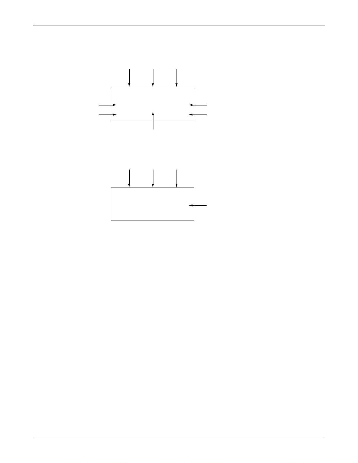
3-1 Installing a Battery Pack
1. To attach the battery pack after charging, align it with the phone about 1cm (1/2 inch away from its place so
that the two arrows on the phone are seen, the battery charge contacts pointing downward.
2. Slide the battery pack upwards until it clicks firmly into position. The phone is now ready to be turned on.
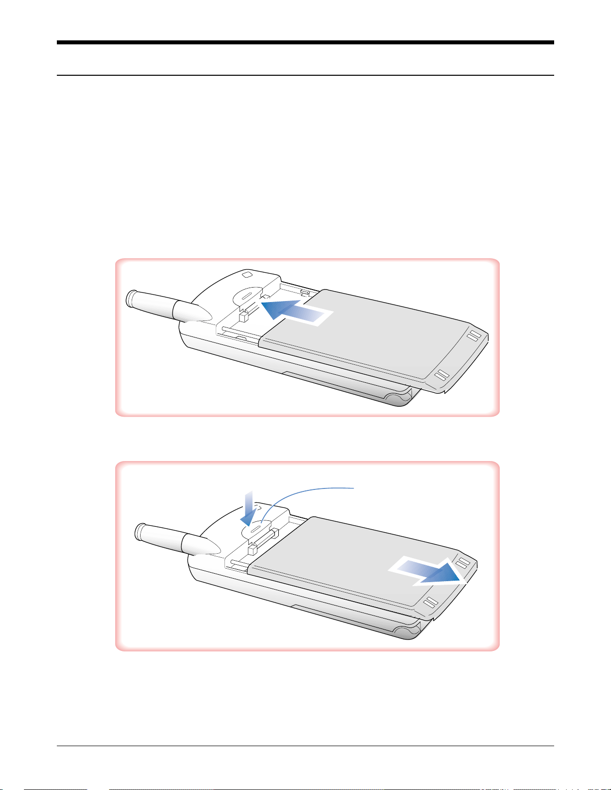
3. To remove the battery pack, release it by pressing the button on the rear of the phone.
4. Slide the battery pack downward about 1cm (1/2inch and lift it away from the phone.
Press this button to
release the battery pack

SAMSUNG Proprietary-Contents may change without notice
3-2
Installation
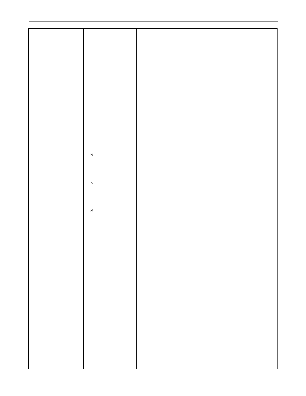
3-2 For Desk Top Use
1. Choose a proper location to install the charger for Desk Top use.
2. Plug the power cord of the charger into an appropriate wall socket. When the power is connected correctly,
the lamps turn on briefly.
3. To charge the battery pack, insert the battery pack into the rear slot of the charger. The lamp marked BAT on
the front panel of the charger lights up red.
4. If you do not wish to use the phone while charging the battery, insert the phone with the battery pack
attached into the front slot of the charger. The lamp marked PHONE on the front panel of the charger lights
up red.
Figure 3-1 Charging the Phone and Battery
SPECIFICATIONS USING “DTC 61AB”
Product Charging time (hours) Stand by time (hours) Talking time(min)
Front Rear Digital Digital
Slim Battery Pack (Li-ion: 500mAh) 2 2 40 80
Standard Battery Pack (Li-ion: 1000mAh) 2 2 75 150
Extended Battery Pack (Li-ion: 1600mAh) 2.5 6 120 240
Item Model Name Service Part#
Desk Top Rapid Charger DTC61AB GH44-00063A
Slim Battery Pack BTI61AB GH43-00023A
Standard Battery Pack BTS61AB GH43-00022A
Extended Battery Pack BTE61AB GH43-00021A
SLIM
BATTERY PACK
STANDARD
BATTERY PACK
EXTENDED
BATTERY PACK
SAMSUNG Proprietary-Contents may change without notice
3-3
Installation
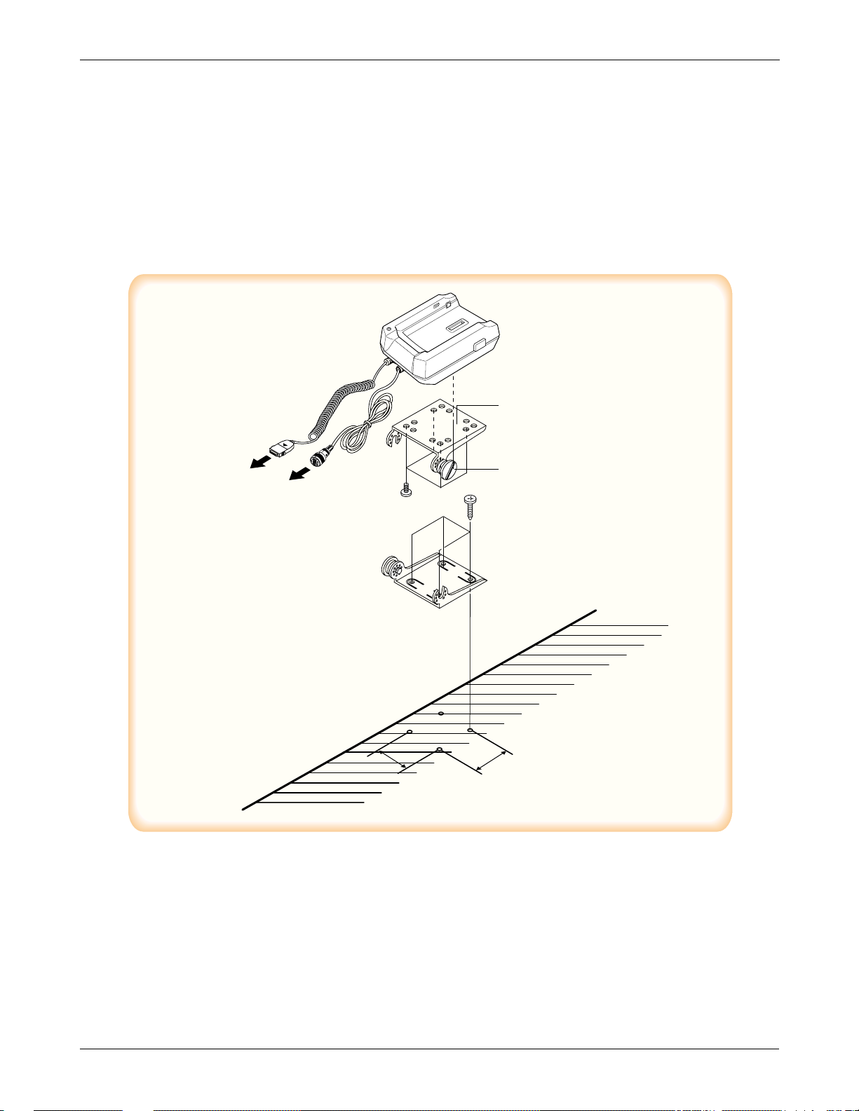
3-3 For Mobile Mount
3-3-1 Cradle
1. Choose a location where it is easy to reach and does not interfere with the driver’s safe operation of the car.
2. Separate the two halves of the clamshell by removing the two large slotted screws. See the figure 3-2.
3. Drill holes and mount the lower half of the clamshell by using the screws.
4. Place the cradle onto the remaining half of the clamshell and assemble them by using the screws.
5. Reassemble the two halves of the clamshell together. Adjust the mounting angle and tighten the two slotted
screws.
Figure 3-2 Cradle Installation
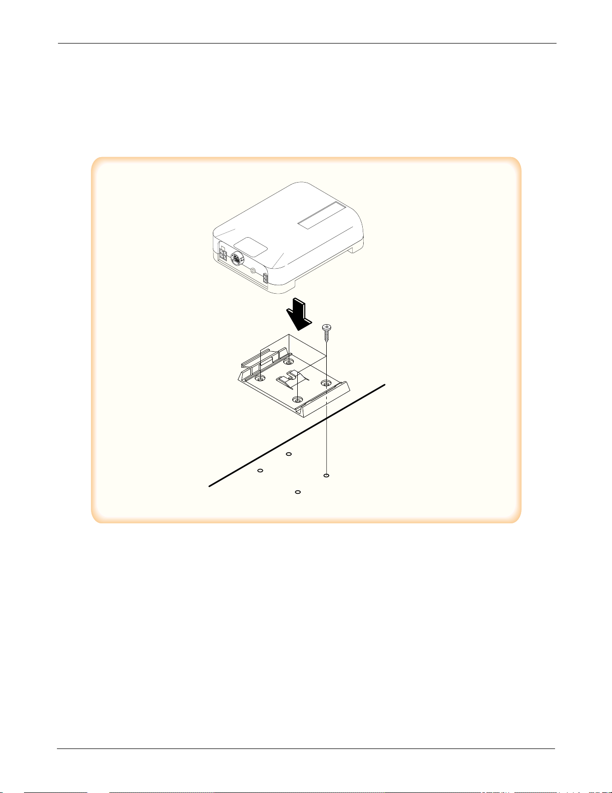
3-3-2 Hands-Free Box
1. Drill holes in a proper location for the hands-free box, attach the mounting bracket by using the screws. See
the figure 3-3.
2. Install the hands-free box into the bracket.
HANDS
FREE BOX
CELLULAR
PHONE
CRADLE
CLAM SHEEL
MOUNT UPPER
CLAM SHEEL
MOUNT LOWER
FIXED SCREW
CAR
32
32
SAMSUNG Proprietary-Contents may change without notice
3-4
Installation
3-3-3 Hands-Free Microphone
1. It is recommended to install the microphone where it is 30-45 cm (12-18inch away from the driver. Choose
the location where is least susceptible to interference caused by external noise sources, ie, adjacent windows,
radio speakers, etc. Normal place is the sun visor.
2. Once the microphone has been correctly positioned, connect the microphone wire to the MIC jack on the
hands-free box.
Figure 3-3 Hands-Free Box 1 Installation
MOUNTING BRACKET
Yellow(Ignition)
Micro Phone
White(Stereo Mute)
Red(Vehicle Battery)
Black(GND)
SAMSUNG Proprietary-Contents may change without notice
3-5
Installation
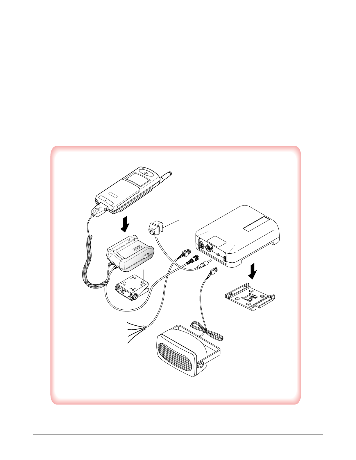
3-3-4 Cables
1. Connect the cradle and the hands-free box with the data cable. See the figure 3-4.
2. Connect the antenna cable to the RF jack of the cradle.
3. Connect the power cable as follows:
Connect the red wire to the battery (+) terminal, black wire to the vehicle chassis. Then connect the battery (-)
terminal to the vehicle chassis. Connect the yellow wire to the switched side of the ignition switch, and then
connect the white to the stereo mute wire from your vehicle stereo.
4. Connect the other end of the power cable to the PWR jack of the hands-free box.
Notes:
It is recommended to connect the power cable directly to the battery to avoid power noise.
Make sure the connection, in the vehicle, between the battery (-) terminal and vehicle chassis is made correctly.
Make sure the fuse having a proper capacity is used on the power cable.
Make sure the cables do not pass over any sharp metal edge that may damage it.
4. NAM Programming
NAM features can be programmed as follows:
Notes:
-If you enter the NAM program mode, each item shows the currently stored data. Go to the next item by
pressing OK.
-You can modify the data by entering a new data.
-If you enter a wrong digit, press CLR to delete the last digit. Press and hold CLR to delete all digits.
-To scroll items backwards or forwards, press the VOLUME button on the left side of the phone.
4-1 General Setup
LCD Display Key in Function
47 869#08#9 -selects NAM programming
NAM program 1 -choose ‘GENERAL’
1:General
2:Setup NAM1
3:Setup NAM2
ESN Volume ▼ -Electronic Serial Number of the phone is displayed
E9031F77
CAI version Volume ▼ -Common Air Interface version is displayed
3
VOC8/13/EVRC
SO_VOIC_EVRC Volume ▼ -Vocoder Rate
SCM Volume ▼ -Station Class Mark displays the power class,
00101010 transmission, slotted class, dual mode.
Lock Code Lock code, current ststus is displayed
0000 4-digit code -to change, enter new code.
OK -store it
Slot Mode Slot mode. ‘Yes’ indicates the slot mode.
Yes or # -changes the status.
OK -store it.
Slot Index Slot mode index. The higher, the longer sleeping time
2 0-7 -to change, enter new one.
OK -store it.
Pref NAM(1~4)... Preferred system selection for NAM(1~4).
Digital only o r # Up to four NAMs are allowed for the phone. This lists
OK one of the four NAMs and allows you to program
CDMA settings.
SAMSUNG Proprietary-Contents may change without notice
4-1

SAMSUNG Proprietary-Contents may change without notice
4-2
NAM Programming
4-2 Setting Up NAM1
LCD Display Key in Function
NAM Program 2 -Choose ‘Setup NAM1.’
1:General
2:Setup NAM1
3:Setup NAM2
Setup NAM1 1 -Choose ‘Phone #’
1:Phone #
2:CDMA
Phone # -directory number
1234567890 Phone number -to change, enter new one.
OK -store it.
Mobile ID # -Phone number currently used.
1234567890 Phone number -to change, enter new one.
OK -store it.
Setup NAM1 2 -choose ‘CDMA’
1:Phone #
2:CDMA
IMSI_MCC IMSI Moble Country Code, current code is displayed.
000 number -to change, enter new one.
OK -store it.
IMSI_MNC IMSI Mobile Network Code, current code is displayed.
00 number -to change, enter new one.
OK -store it.
CDMA pref.. Preferred system selection, current system is displayed.
A only or # -changes the system.
OK -store it.
CDMA ACCOLC CDMAAccess Overload Class, current status is displayed.
0 class number -to change, enter new one.
OK -store it.
Pchn Sys A Preferred channel currently used under system A
779 channel number -to change, enter new one.
OK -store it.
Pchn Sys B Preferred channel currently used under system B
779 channel number -to change, enter new one.
OK -store it.
SAMSUNG Proprietary-Contents may change without notice
4-3
NAM Programming
LCD Display Key in Function
Schn Sys A Second channel currently used under system A
738 channel number -to change, enter new one.
OK -store it.
Schn Sys B Second channel currently used under system B
738 channel number -to change, enter new one.
OK -store it.
CD Acq SID 1 1st Acquisition system ID, current status is displayed.
0 ID number -to change, enter new one.
OK -store it.
CD lockSID 1 1st lock system ID,current status is displayed.
0 ID number -to change, enter new one.
OK -store it.
CDMA Home SID CDMA Home system ID, current status is displayed
Yes or # -changes the status.
OK -store it.
CDMA fSID CDMA foreign SID, current status is displayed.
Yes or # -changes the system.
OK -store it.
CDMA fNID CDMA foreign NID, current status is displayed.
Yes or # -changes the system.
OK -store it.
SID #1 first SID written in the list, current status is displayed.
2222 number -to change, enter new one.
OK -store it.
NID #1 first NID written in the list, current status is displayed.
1 number -to change, enter new one.
OK -store it.
SID #2 2nd SID written in the list, current status is displayed.
2222 number -to change, enter new one.
OK -store it.
NID #2 2nd NID written in the list, current status is displayed.
2 number -to change, enter new one.
OK -store it.
SID #3 3rd SID written in the list, current status is displayed.
2222 number -to change, enter new one.
OK -store it.

SAMSUNG Proprietary-Contents may change without notice
4-4
NAM Programming
4-3 Setting Up NAM 2, 3, 4
The NAM 2, 3, 4 setup program is the same as ‘4-2 Setting Up NAM1’.
LCD Display Key in Function
SNID #3 3rd SID written in the list, current status is displayed.
3 number -to change, enter new one.
OK -store it.
SID #4 4th SID written in the list, current status is displayed.
2222 number -to change, enter new one.
OK -store it.
NID #4 4th NID written in the list, current status is displayed.
15 number -to change, enter new one.
OK -store it.
Setup NAM1 LCD returns to the NAM1 setup mode.
1:Phone #
2:CDMA

SAMSUNG Proprietary-Contents may change without notice
5-1
5. Product Support Tools
5-1 General
IMPORTANT INFORMATION
Purpose
The Product Support Tool (PST) offers you the ability to interface with the SAMSUNG CDMA telephone using
a PC. With this tool you can program the phones network system requirements and functionality, swap phone
data, and download software upgrades. This document supports UniPST version 1.xx.
NOTE: This software must be executed in the Windows95/98 mode.
EQUIPMENT REQUIRED
Make sure you have the following equipment setup:
1. Minimum PC configuration: 586 CPU, 16MB RAM, Windows95/98, 5MB of disk space free for software
upgrade.
2. PST Software with appropriate cable (DM Cable for SAMSUNG CDMA phone).
3. Serial Port (16550 Serial Interface Card).
4. Power Supply (3.8 V) or Battery
INST
ALLATION
Software
1.Insert the PST floppy disk into drive (A:\).
2.Create an appropriate directory on the C:\ drive for PST software, Execute Setup.exe file,
The installation program creates folder and task bar on the windows95/98 start bar.
SAMSUNG CDMA Phone
The serial port should be configured to COM1 or COM2.
Use the following procedure to connect the phone, cable, and PC .
Plug the female end of the DM Cable into the 16550 card.
Pull the black rubber connector away from the socket at the base of the phone.
Plug the special connector on the cable into the socket at the base of the phone.

SAMSUNG Proprietary-Contents may change without notice
5-2
Product Support Tools
5-2. PST (Product Support Tool)
5-2-1 Getting Started
MAIN MENU SCREEN
1. At the Windows95/98, Double Click “UniPst.exe”.
2. The Main Menu Screen will be displayed.
The Main Menu Screen shows the basic tasks that are available.
CAUTION: DO NOT attempt to program phone with a low battery.
PST SETUP
UniPst supports SAMSUNG CDMA portable telephone. You can select serial port COM1 or COM2.
5-2-2 Operation Procedure
Service Programming
The Service Programming screens enable you to set and change the service activation parameters of the
phones. These items can be changed individually or as a group via the “Edit Items” Property Sheet of the PST.
There are several pages on the Service Programming Property Sheet (See below Figure).
Read Data from File
Click “open” icon to select the name of a file whose extension is “mmc”. The values will be read from the
named file, and will initialize the parameter values seen on the Service programming screen
Read Data from Phone
Click Read from the Phone icon to upload the current programmable parameters of the phone. The values are
read from the phone, so the phone must have the power ON and be properly connected to the PST.
NOTE: To actually view the data you need to go to the Edit Items screens.
Edit Items
Click this icon to edit Number Assignment Module (NAM) items or UI items.
There are two types of screens:
1. Parameters associated with a particular Number Assignment Module (NAM)
2. UI items settings
Phone Book
Click this icon to edit Phone Book.
While you edit cell, you can use <Enter> and < UP , DOWN,LEFT,LIGHT Arrow> and <SPACE> key. If you
want to edit phone number or name , you must move rectangle box to cell where you want to edit , Write it
down . if <UP and DOWN Arrow> key is pressed, the cursor moves to next cell or previous cell.

SAMSUNG Proprietary-Contents may change without notice
5-3
Product Support Tools
Save Data to File
Click this icon to save the current parameters to a file. Once you enter a filename, Click <OK> button to write
all current parameters to that file. This way the same information can be downloaded into multiple phones.
Write to Phone
Click this icon to write the selected parameter values to the phone. Writing the selected values to the phone
may take up to a minute.
If there are dependencies in a field you can make all the changes in the proper fields and download the
information all together.
If you intend to use this “Write to Phone” feature, it is recommended that you do a “Read Data from Phone”
first, and then make the changes, so that nothing gets inadvertently overwritten.
NOTE: DO NOT TOUCH THE PHONE WHILE WRITING IS IN PROGRESS.
Software Download and Upgrade Screen
To begin a software upgrade or download, perform the following steps:
1. From the main menu screen choose DOWNLOAD MODE?
Click open icon to choose a BIN file of the new software to be loaded. Choose the appropriate BIN file, then
Click <Open> (see below figure).
2. Click Download? to begin downloading the file. You will notice various messages and a progress bar that
informs the user what percentage of the downloading has already occurred.
3.Click Mode Select box, then Select SERVICE MODE?to return to the Service Mode Screen.
NOTE: DO NOT POWER OFF WHILE THE PHONE IS BEING DOWNLOADED!
Test Jig
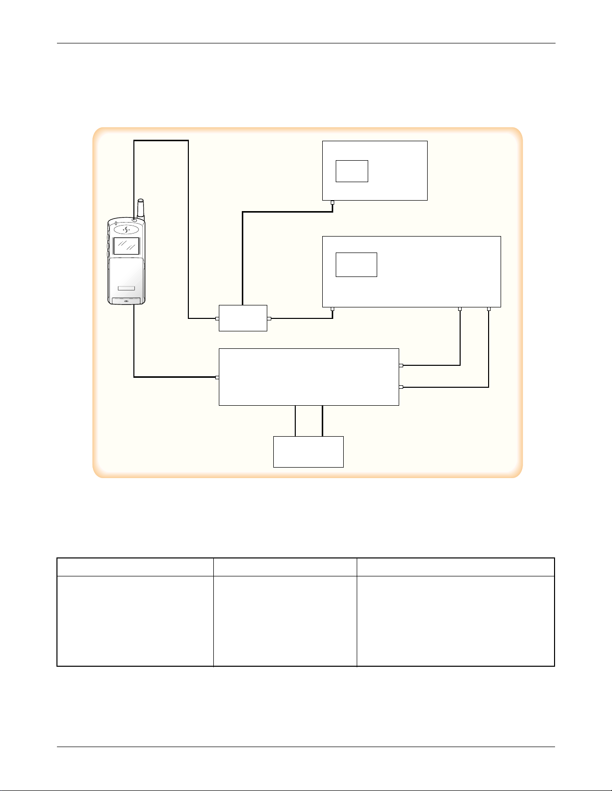
5-3 TEST PROCEDURE
5-3-1 Configuration of Test
SAMSUNG Proprietary-Contents may change without notice
5-4
Product Support Tools
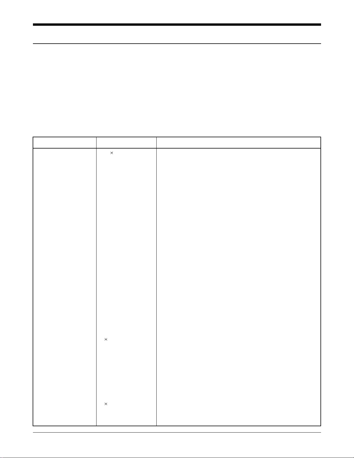
ITEMS PARTS # REMARK
RF test Cable GH39-00002A
Test cable GH39-30516A
DM Cable GH39-30525A
Test JIG GH80-10502A Including
(RF Interface Pack Ass’y) 1. Power Cable(Black,Red)
2. 9-pin RS232 data Cable
❈ CAUTION : Because there is the loss (0.33V at Max Power) of the test jig and Data cable, you’d better input
3.93V to the DC Power Supply to use 3.6V (Battery normal voltage) at Cellular phone
Items needed to purchase from SAMSUNG
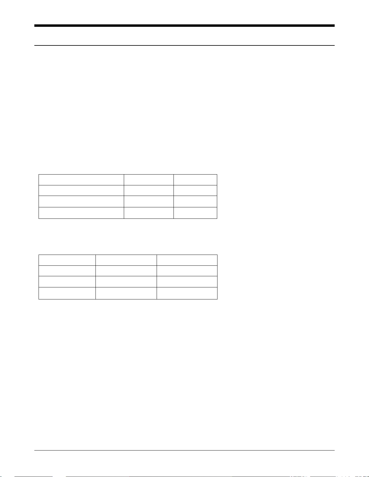
Spectrum Analyzer
HP8924C
RF In
RF
In/Out
Audio
Out
Audio
In
Directional
Coupler
To A-Out
To A-In
DC Power Supply
(+3.93V)
SAMSUNG Proprietary-Contents may change without notice
5-5
Product Support Tools
5-3-2 List of Equipment
- DC Power Supply
- Test Jig
- Test Cable
- CDMA Mobile Station Test Set HP8924C, HP83236A, CMD-80, etc
- Spectrum Analyzer(include CDMATest Mode) HP8596E
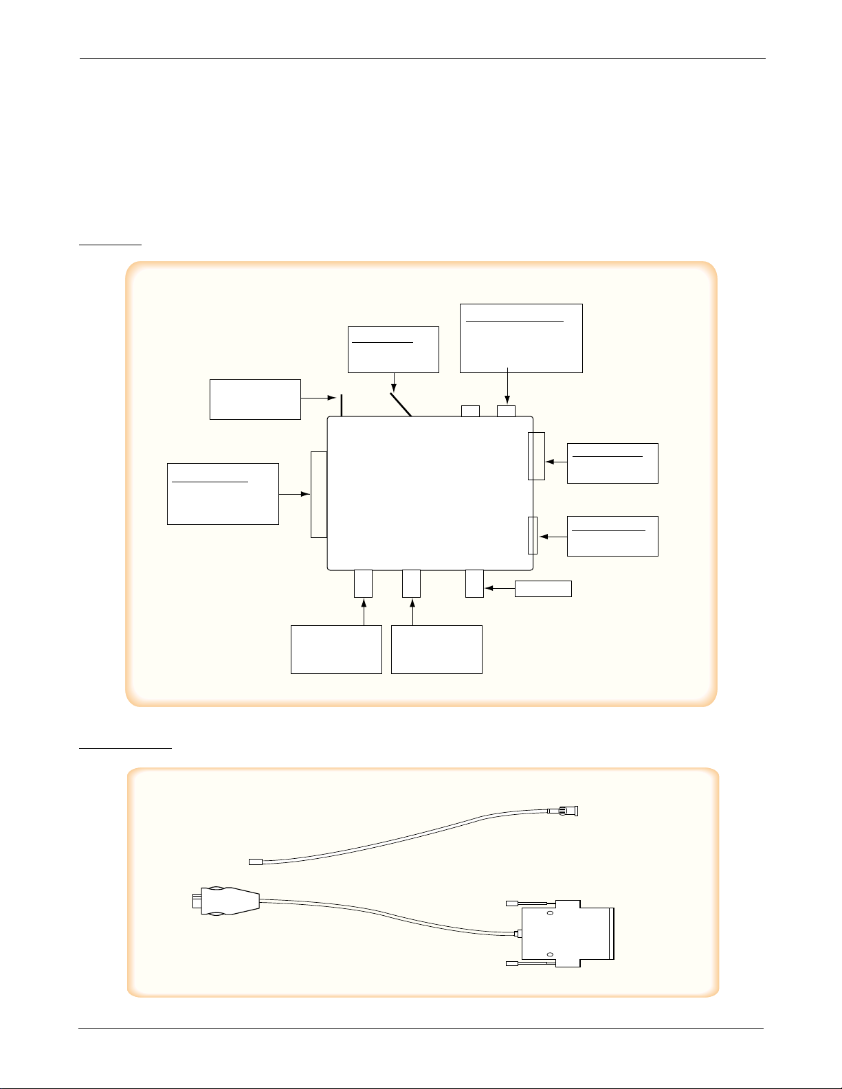
TEST CABLE
TEST JIG
AUDIO SELECT
LEFT : AUDIO IN
RIGHT : AUDIONOFF
DC POWER INPUT POR
T
CHANGE VOLTAGE LEVEL
BY MODEL (3.8VDC)
RED: +
BLACK: GND
D89 CONNECTOR
CONNECT TO IBM
PC SERIAL PORT
BJ1
1 CONNECTOR
CONNECT TO HP
SERIAL PORT
NOT USED
CONNECT TO
AUDIO IN PORT OF
TEST EQUIPMENT
(USE BNC CABLE)
CONNECT TO
AUDIO OUT PORT OF
TEST EQUIPMENT
(USE BNC CABLE)
DB25 CONNECT
OR
CPMMECT TO
DB25 CONNECTOR
OF TEST CABLE
UP: AUTO POWER ON
DOWN: NOT USE
AUTO
TO
A-OUT
TO
A-IN PROBE
HHP I/F TEST JIG
T
E
S
T
P
A
C
K
A-IN - DC3.8v +
TO_PC
TO_HP
1
2
3
4
5
6
TEST CABLE CONNECTIONS
1 MHC 172
2 RF CABLE (1.4 dB Loss)
3 BNC CONNECTOR (RF)
4 PLUG CONNECT TO SCH-611
5 DATA CABLE
6 Dsub 25PIN CONNECTOR (DATA)
SAMSUNG Proprietary-Contents may change without notice
5-6
Product Support Tools
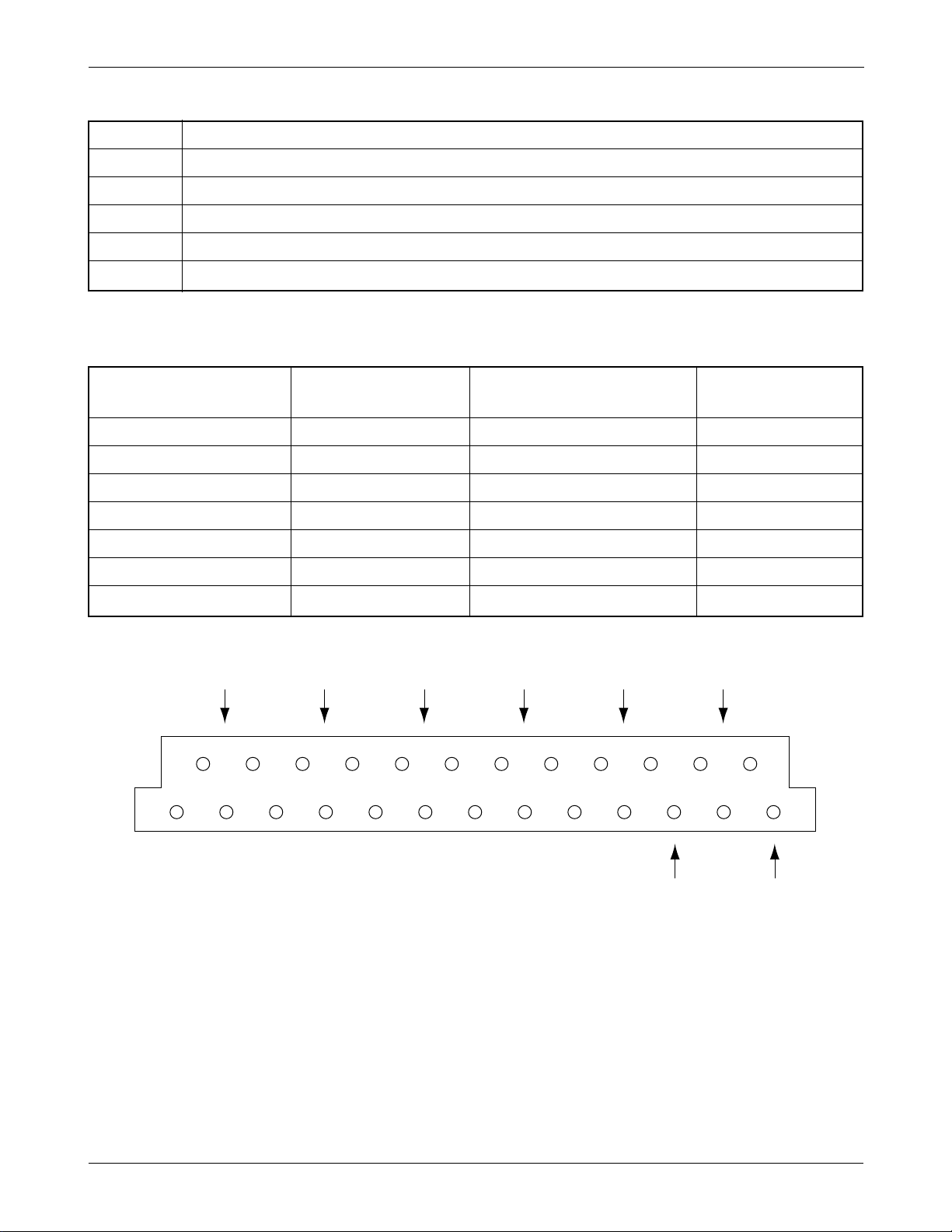
Dsub 25 PIN CONNECTOR PIN DESCRIPTION (TEST CABLE 1, BACK SIDE)
DATA DESCRIPTION Dsub CONN. DATA DESCRIPTION Dsub CONN.
PIN NO. PIN NO.
V_F 12,21 DP_RX_DATA 8
DGND 2,4,6,13,19 HP_PWR 9
BATT 15,16,22 RI 10
C_F 3,20 CD 11
TX_AUDIO 5 RTS 14
DP_TX_DATA 7 CTS 17
RX_AUDIO 1 DTR 18
15 17 19 21 23 25
14 16 18 20 22 24
246810
1357911 1312

SAMSUNG Proprietary-Contents may change without notice
5-7
Product Support Tools
5-4. CONVERSION TABLE OF FREQUENCY vs CHANNEL
T Y P E CHANNEL CONVERSION EQUATION REMARK
TX 1 ≤ N≤ 799 F=0.03 ✕ N + 825.00
FREQUENCY 990 ≤N≤1023 F=0.03 ✕ (N-1023) + 825.00
RX 1 ≤N≤ 799 F=0.03 ✕ N + 870.00
FREQUENCY 990 ≤N≤1023 F=0.03 ✕ (N-1023) + 870.00
Change to Test Mode
A. To change the phone’s state from Normal Mode to Test Mode, You should enter the following keys.
“ 7 5 9 # 8 1 3 5 8 0 “
B. The command “0 1” is Suspend.
C. To finish the Test Mode, You should enter the command “0 2”.
Channel Selection and Tx Power Output Level Control (Digital Mode)
A. Enter to Test Mode ( 7 5 9 # 8 1 3 5 8 0 ).
B. “0 1” : Suspend.
C. “0 9 0 3 6 3 #” : Set to ‘0363’ channel.
D. “0 7” : Carrier On.
E. “3 4” : Spread spectrum to 1.23MHz bandwidth.
F. “7 1 2 7 5 #” : Output RF power level setting.
“275” means AGC level and AGC level range is from 0 to 511.
N ; CH NUMBER
F ; FREQUENCY
SAMSUNG Proprietary-Contents may change without notice
6-1
6. Troubleshooting
6-1 Logic Section
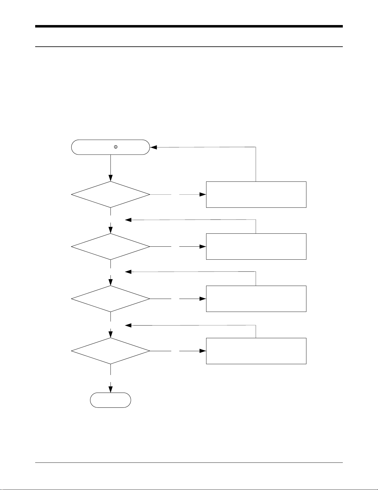
6-1-1 No Power
Check the signal from the battery
terminal to U 105 pin 1.
Check U105 and its neighboring
circuits.
Check U106 and its neighboring
circuits.
Check U211 and its neighboring
circuits.
Press button
U208 pin 13=3.6V?
U210 pin 4 input
=4V?
U210 pin 5 output
=3.7V?
U107 pin 5 output
=3.7V?
END
Yes
Yes
Yes
Yes
No
No
No
No
END/
SAMSUNG Proprietary-Contents may change without notice
6-2
Troubleshooting
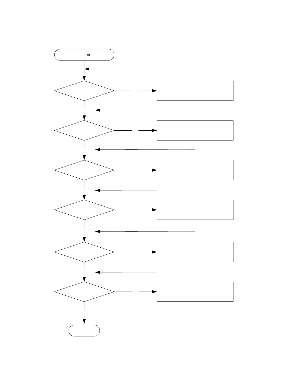
6-1-2 Abnormal Initial Operation (Normal +3.3V source)
TCXO CLK
applied to U401 pin 26?
Check TCXO output,
R400 and C400.
Replace if required.
Check U401 and its meighboring
circuit. Replace if required.
Check U109, MSM and its
neighboring circuits.
Check ‘H’ level input from J104
pin 17 to U401 pin 79.
replace if required.
Check Q125 and its neighboring
circuit. Replace if required.
Check the LCD pins and its
neighboring circuit.
Replace if required.
TCXO CLK signal output
from U401 pin 29?
RAM-CS signal output
from U109 pin 44?
CHIPX8 CLK signal output
from U401 pin 52?
Alert LED ON?
Normal initial
display on LCD?
END
Yes
Yes
No
No
Yes
No
Yes
No
Yes
Yes
No
No
Press button
END/
SAMSUNG Proprietary-Contents may change without notice
6-3
Troubleshooting
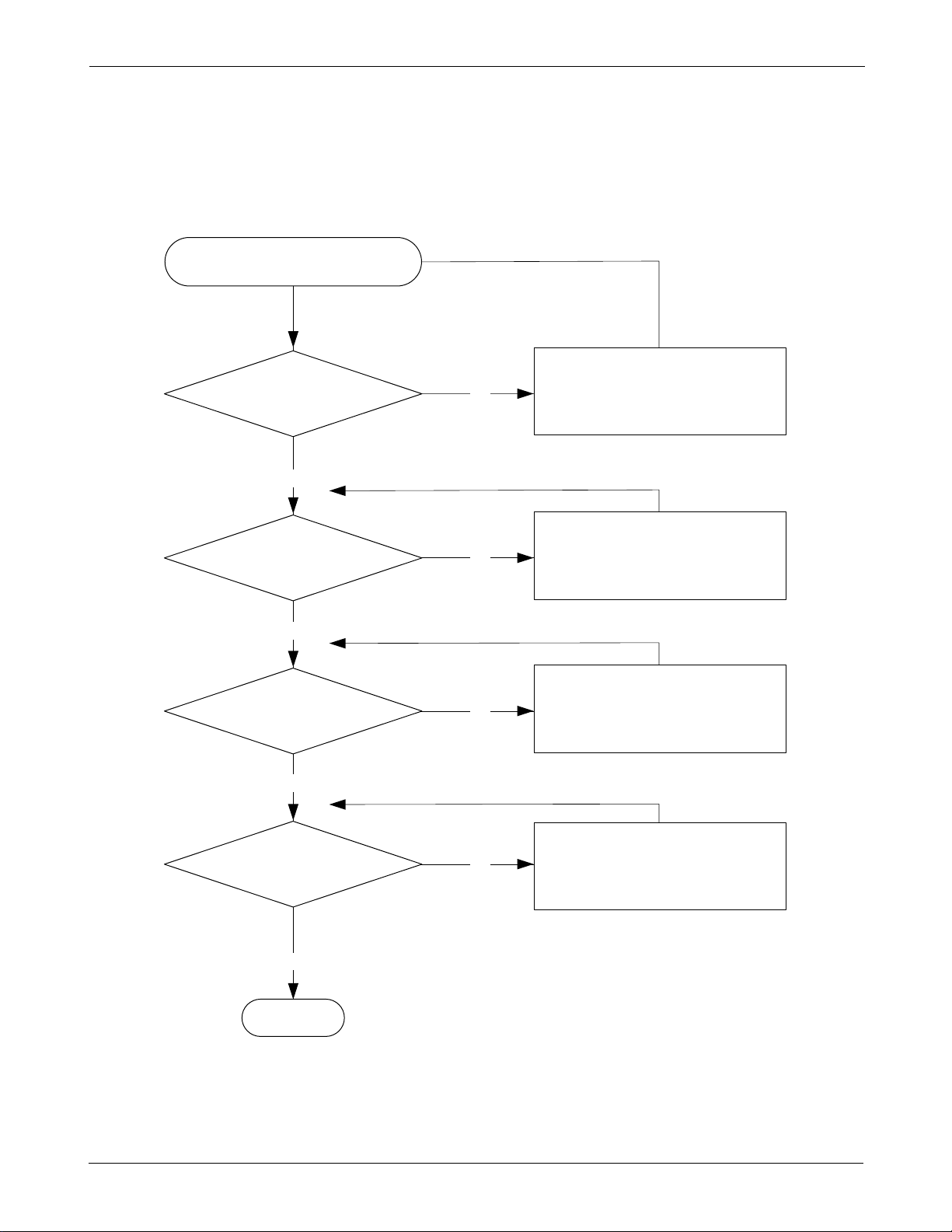
6-1-3 Abnormal Backlight Operation
Press and button on the phone
‘H’ level output from
U101 L7 to J105 pin 19?
‘H’ level input to
U139 pin 4,5?
Normal U139 operation?
Normal EL?
EL ON
Check EL.
Replace if required
Check U139, L201, Q139
and its neighboring circuits.
Replace if required
Check FPC.
Replace if required
Check U101 L7.
Replace if required
Yes
No
Yes
No
Yes
No
Yes
No
SAMSUNG Proprietary-Contents may change without notice
6-4
Troubleshooting
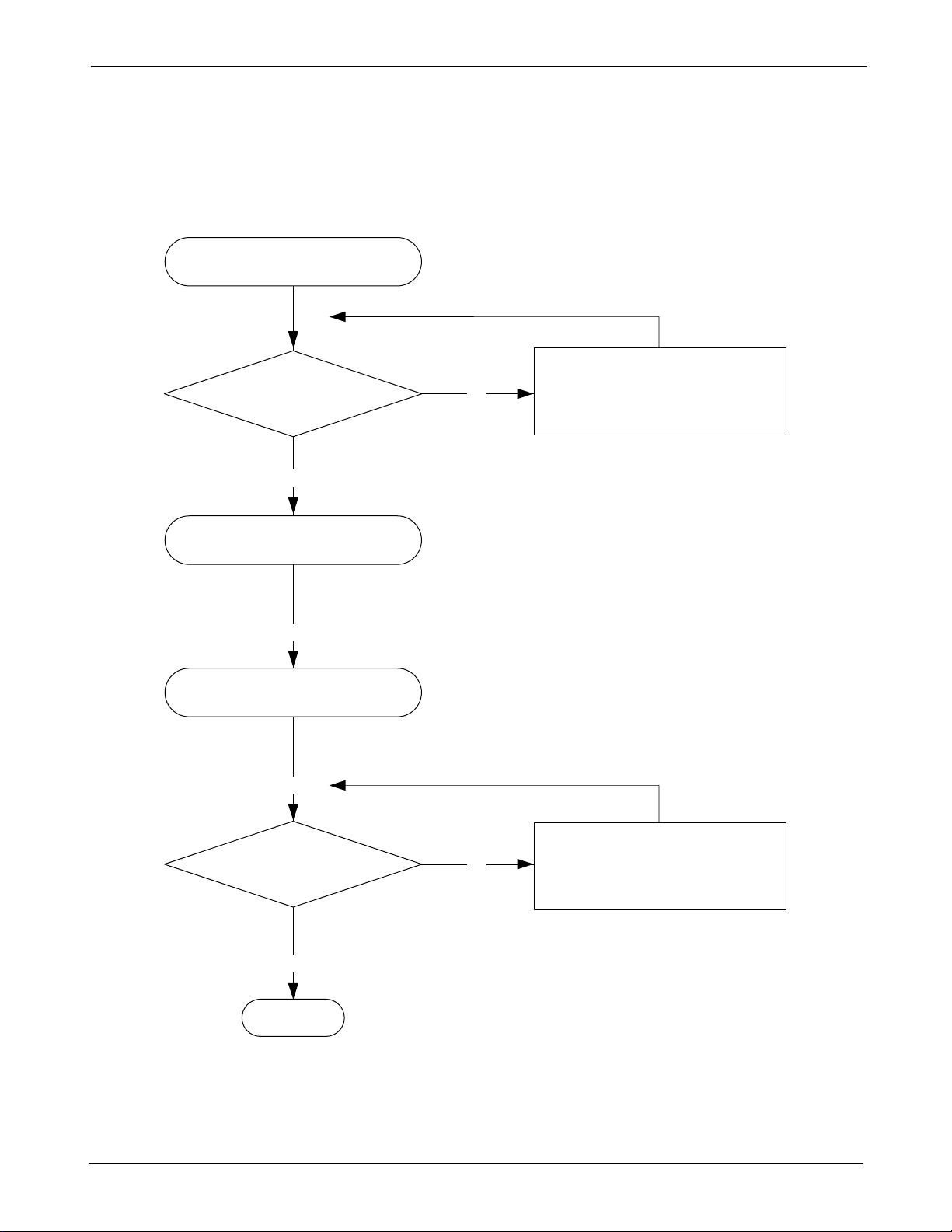
6-1-4 Abnormal Key Data input
Check initial status
Scanning signals
output from U101, C5, B4, D5, A5
C6, A5, D6
Check U101
Check U101 A2, A3, C4, B5, E5
Check J103
Normal key data input?
Replace the key pad assembly
END
Yes
Yes
Yes
Yes
No
No
 Loading...