

Samsung SCH-3500 Service Manual
SERVICE
PORTABLE CELLULAR
TELEPHONE
SCH-3500 Series
GHI
PQRS
ABC
JKL
SPACE
TUV
DEF
MNO
WXYZ
Manual
PORTABLE CELLULAR TELEPHONE CONTENTS
1. General Introduction
2. Specification
3. Installation
4. NAM Programming
5. Product Support Tools
6. Circuit Description
7. Test Procedure
8. Trouble Shooting
9. Exploded Views and Parts List
10. Block Diagram
11. Electrical Parts List
12. PCB Diagrams
13. Circuit Diagrams

SAMSUNG Proprietary-Contents may change without notice
1-1
1. General Introduction
The SCH-3500 DBDM(Dual Band Dual Mode) phone functions as both analog phone working in AMPS
(Advanced Mobile Phone Service) mode and digital phone working in PCS (Personal Communication Service)
mode.
The following standards and minimum performance standards shall be met or exceeded by each subscriber
unit.
Air Interface
The Subscriber Unit shall be Dual mode and Dual band in compliance with ANSI J-STD-008 and TIA/EIA IS95A(Analog).
ANSI J-STD-008 : Personal Station-Base Station Compatibility Requirements for 1.8 to 2.0 GHz CDMA PCS.
ANSI J-STD-018 : Recommended Minimum Performance Requirements for 1.8 to 2.0 GHz CDMA Personal
Stations.
CDG Ref. Document #27 : High Rate Speech Service Option for Wideband Spread Spectrum System.
TIA/EIA IS-96A : Speech Service Option 1 Standard for Dual mode Wideband Spread Spectrum Cellular
Systems.
TIA/EIA IS-125 : Recommended Minimum Performance standards for Digital Cellular Wideband Spread
Spectrum Speech Service Option1.
TIA/EIA IS-126-A : Mobile Station Loop back Service Option standard.
TIA/EIA IS-95A : Mobile Station-Base Station Compatibility Standard for Dual-Mode Wideband Spread
Spectrum Cellular Systems;for the analog air interface.
TIA/EIA IS-98A : Recommended Minimum Performance Requirements for 1.8 to 2.0 GHz CDMAPersonal
Stations.
CDMA Receiver/Transmitter Specifications and Requirements
The Subscriber Unit shall comply with ANSI J-STD-008 and meet or exceed TIA/EIA IS-98A. The Subscriber
Unit shall comply with Personal Station Class II.
Analog Receiver/Transmitter Specifications and Requirements
The Subscriber Unit shall comply with TIA/EIA IS-95A and meet or exceed TIA/EIA IS-95. The Subscriber Unit
shall comply with Mobile Station Power Class III (600 mW).
2. Specification
2-1 General
Frequency Range PCS Mode AMPS Mode
Transmitter 1850 ~ 1910 MHz 824 ~ 849 MHz
Receiver 1930 ~ 1990 MHz 869 ~ 894 MHz
Channel Spacing 1.25 MHz 30 kHz
Number of Channels 1200 832
Duplex Spacing 80 MHz 45 MHz
Frequency Stability (FRX - 80 MHz) ± 150 Hz ± 2.5 ppm
Operating Temperature -30 oC ~ 60 oC
Operating Voltage
HHP 3.6V DC (± 10%)
Hands-free 13.7V DC (± 10%)
Size and Weight
Including standard battery 11.2 x 5.2 x 2.5 cm, 146 cc, 146 g (5.1 ounces)
Including extended-life battery 11.2 x 5.2 x 3.0 cm, 175 cc, 166 g (5.8 ounces)
SAMSUNG Proprietary-Contents may change without notice
2-1

SAMSUNG Proprietary-Contents may change without notice
2-2
Specification
2-2 AMPS Mode
TRANSMITTER
RF output power : 0.6 W (+2/ - 4 dB)
Carrier ON/OFF Conditions
“ON” Condition : within ± 3 dB of specification output (in 2mS)
“OFF” Condition : below - 60 dBm (in 2mS)
Compressor
Compression Rate : 2:1
Attack Time : 3 mS
Recovery Time : 13.5 mS
Reference Input : Input level for producing a nominal ± 2.9 kHz peak
frequency deviation of transmitted carrier
Preamphasis : 6 dB/OCT within 0.3 ~ 3 kHz
Maximum Frequency Deviation
F3 of G3 : ±12 kHz (± 10 %)
Supervisory Audio Tone : ± 2 kHz (± 10 %)
Signaling Tone : ± 8 kHz (± 10 %)
Wideband Data : ± 8kHz (± 10 %)
Post Deviation Limiter Filter
3.0 kHz ~ 5.9 kHz : above 40LOG (F/3000) dB
5.9 kHz ~ 6.1 kHz : above 35 dB
6.1 kHz ~ 15 kHz : above 40 LOG (F/3000) dB
Over 15 kHz : above 28 dB
Spectrum Noise Suppression
For All Modulation
f0+ 20 kHz ~ f0+ 45 kHz : above 26 dB
For Modulation by Voice and SAT
f0+ 45 kHz : above 63 + 10LOG (Py) dB
For Modulation by WBD (without SAT) and ST (with SAT)
f0+ 45 kHz ~ f0+ 60 kHz : above 45 dB
f0+ 60 kHz ~ f0+ 90 kHz : above 65 dB
f0+ 90 kHz ~ 2f
0
: above 63 + 10LOG (Py) dB
(where f0= carrier frequency,
Py = mean output power in watts)
Harmonic and Conducted Spurious Emissions : above 43 + 10 LOG (Py) dB

SAMSUNG Proprietary-Contents may change without notice
2-3
Specification
Frequency Range Maximum Allowable EIRP
25 ~ 70 MHz -45 dBm
70 ~ 130 MHz -41 dBm
130 ~ 174 MHz -41 ~ -32 dBm
174 ~ 260 MHz -32 dBm
260 ~ 470 MHz -32 ~ -26 dBm
470 ~ 1 GHz -21 dBm
RECEIVER
DE-Emphasis : -6 dB/OCT within 0.3 ~ 3 kHz
Expander
Expansion Rate : 1:2
Attack Time : within 3 mS
Recovery Time : within 13.5 mS
Reference Input : Output level to a 1000 Hz tone from a carrier within ±
2.9 kHz peak frequency deviation
Sensitivity : 12 dB SINAD/-116 dBm
Intermodulation Spurious Response Attenuation : above 65 dB
RSSI Range : above 60 dB
Protection Against Spurious Response Interference : above 60 dB
In Band Conducted Spurious Emissions
Transmit Band : below -60 dBm
Receive Band : below -80 dBm
Out of Band Conducted Spurious Emissions : below - 47 dBm
Radiated Spurious Emissions

SAMSUNG Proprietary-Contents may change without notice
2-4
Specification
2-3 PCS Mode
TRANSMITTER
Waveform Quality : 0.944 or more
Open loop Power Control Range
-25 dBm : -60.5 dBm ~ 41.5 dBm
-65 dBm : -20.5 dBm ~ -1.5 dBm
-104 dBm : +15.0 dBm ~ +30.0 dBm
Minimum Tx Power Control : -50 dBm below
Closed Loop Power Control Range : ±24 dB
Maximum RF Output Power : 200 mW (+23 dBm)
Occupied Bandwidth : 1.23 MHz
Conducted Spurious Emissions @ 1.25 MHz : -42 dBc/30 KHz
RECEIVER
Rx Sensitivity and Dynamic Range : -104 dBm, FER=0.5% or less
(Rate Set 2) : -25 dBm, FER=0.5% or less
Conducted Spurious Emission
1930 ~ 1990 MHz : <-81 dBm
1850 ~ 1910 MHz : <-61 dBm
All Other Frequencies : <-47 dBm
Single Tone Desensitization : lower than 1%
Rx power = -101 dBm
Tx power = +15 dBm(According to IS-98C)
Tone power = -30 dBm
Tone offset from carrier = ±1.25 MHz
Intermodulation Spurious Response Attenuation : lower than 1%
Rx power = -101 dBm
Tone power 1 = -43 dBm
Tone power 2 = -43 dBm
Tone 1 offset from carrier = ±1.25 MHz
Tone 2 offset from carrier = ±2.05 MHz
SAMSUNG Proprietary-Contents may change without notice
2-5
Specification
IN IDLE MODE
IN CONVERSATION MODE
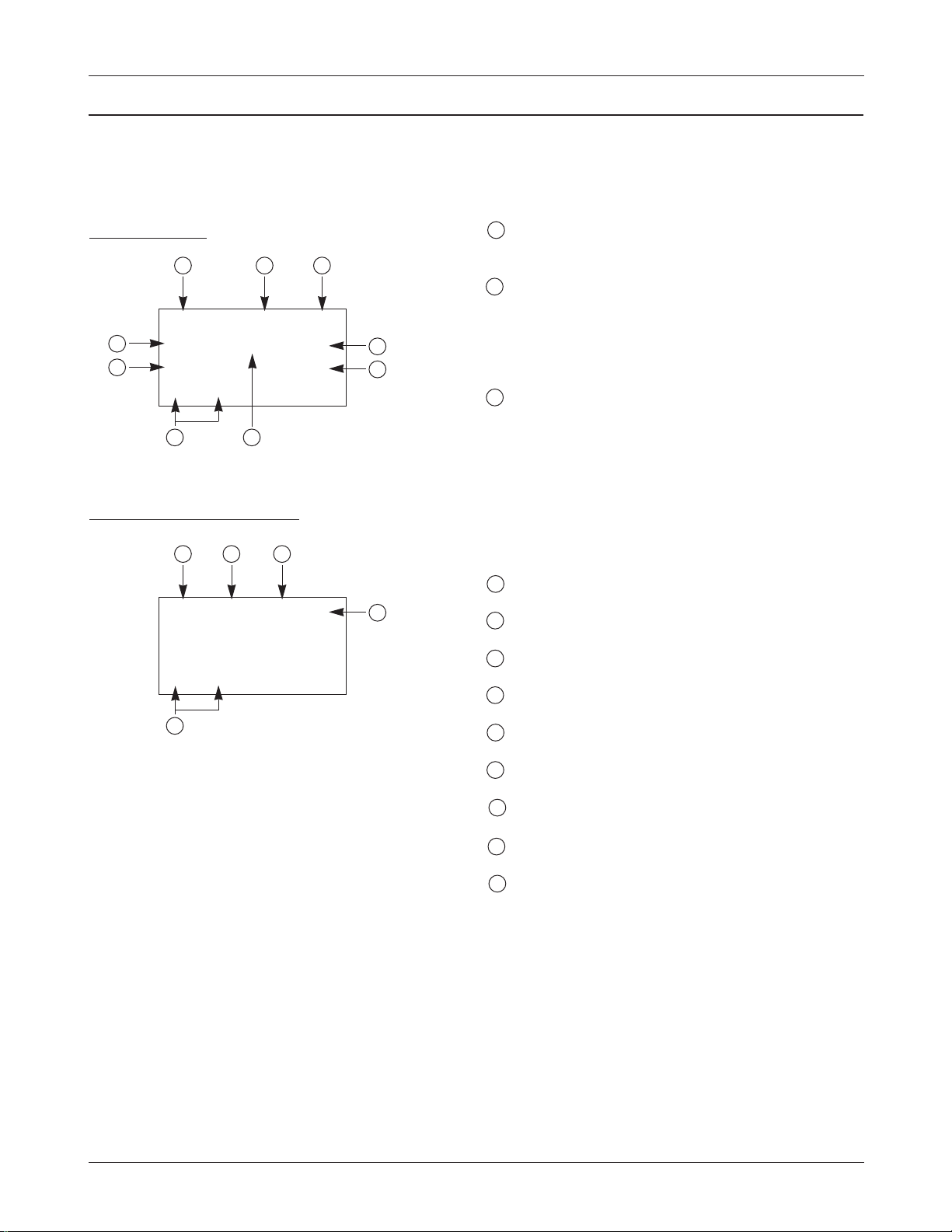
1 Sxxxxx : SID (System Identification) toggle
Nxxxxx : NID (Network Identification) toggle
2 SIx : Slot cycle index (lowest between the system
and the phone will be used)
1. SI0 : Slot Index 0
2. SI1 : Slot Index 1
3. SI2 : Slot Index 2
3 Handset Status : 0 - NO SVC
1 - Synchronization
2 - Paging (Idle)
3 - Reg. Access state
4 - Traffic Initialization
5 - Waiting for order
6 - Waiting for answer
7 - Conversation state
8 - Exit
4 T-xx : Tx adjust, Value ranges from -63~+63dB
5 Dxxx : Sector power in dBm
6 -xx : ec/lo
7 Pxxx : PN offset
8 CHxxxx : Channel number
9 TV : Tx vocoder rate (8 is full rate, 1 is 1/8th rate)
10 RV : Rx vocoder rate (8 is full rate, 1 is 1/8th rate)
11 xx : Walsh code used in traffic channel
12 System acquisition state
2-4 PCS Debug Display Information
To select debug display mode : Press [MENU] + [9] + [0], and press [0] + [4] + [0] + [7] + [9] + [3], and press [1].
Sxxxxx SIx x
T - xx Dxxx - xx
Pxxx CHxxxx
xx xx
1
4
7
6
8
5
12
2 3
TVx RVx xx x
T - xx Dxxx - xx
Pxxx CHxxxx
xx xx
9
3
12
10 11
SAMSUNG Proprietary-Contents may change without notice
2-6
Specification
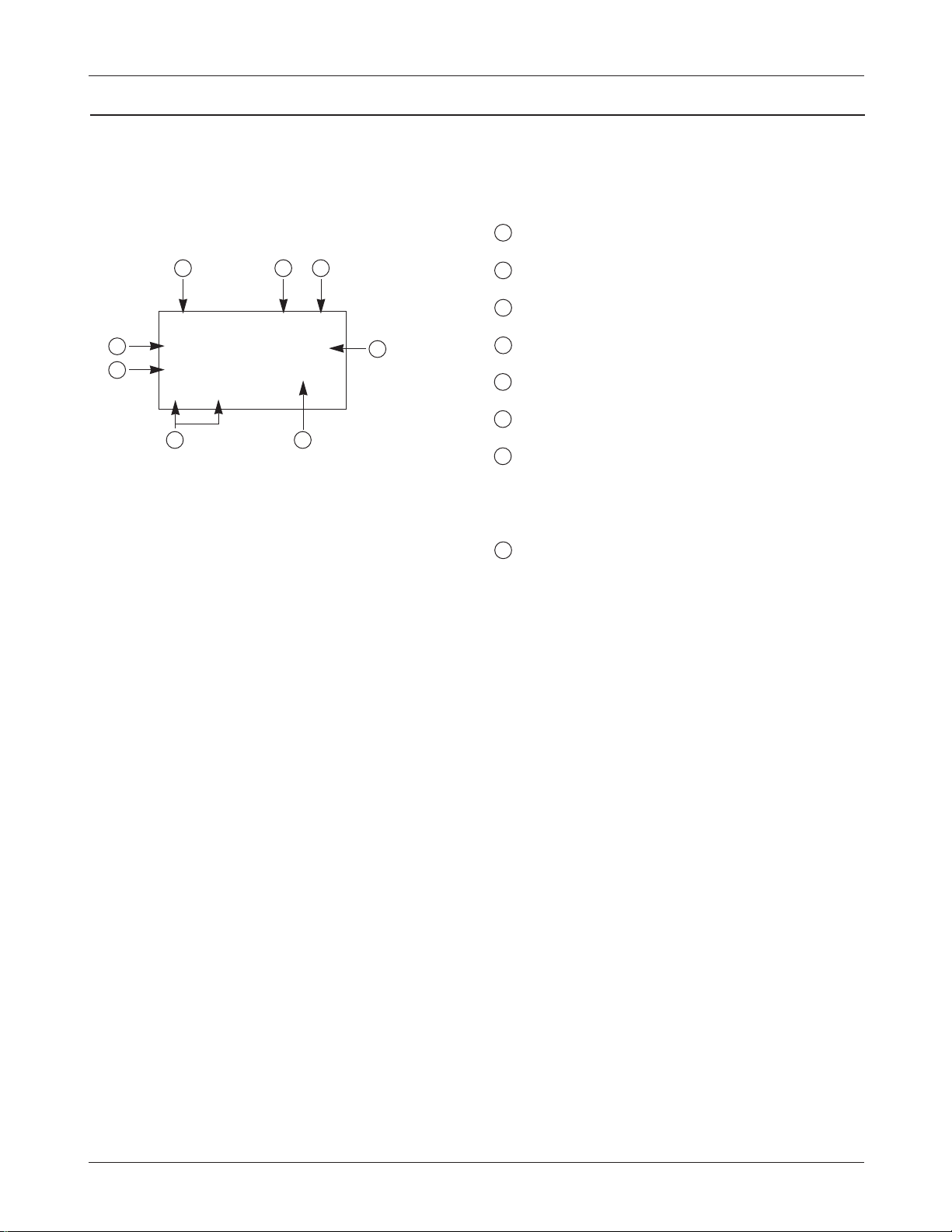
1 SIDxxxxx : AMPS Home System ID
2 PWRx : Power Level 0 ~ 7
3 SATx : Supervisory Audio Tone code (0 ~ 2)
4 x (Using Frequency Band) : ABand or B Band
5 RSSIxxx : RSSI value
6 CHxxx : Channel number
7 Handset Status : 1 - Initialization state
2 - Idle state
3 - System Access state
4 - Voice channel state
8 System acquisition state
2-5 AMPS Debug Display Information
To select debug display mode : Press [MENU] + [9] + [0], and press [0] + [4] + [0] + [7] + [9] + [3], and press [1].
SIDxxxxx x x
PWRx RSSIxxx
SATx CHxxxx
xx xx
1
2
3
5
6
8
7 4
3. Installation
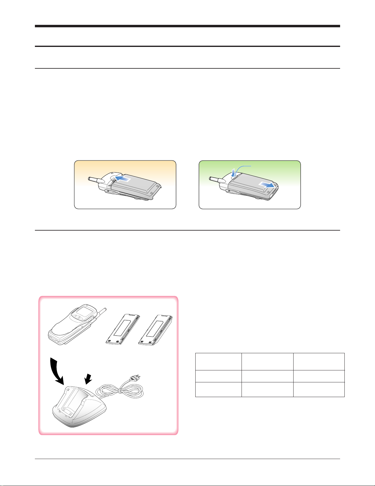
3-1 Installing a Battery Pack
SAMSUNG Proprietary-Contents may change without notice
3-1
Figure 3-1 Charging the Phone and Battery
1. To attach the battery pack after charging, align it
with the phone about 1cm (1/2”) away from its
place so that the two arrows on the phone are
seen, the battery charge contacts pointing
downward.
2. Slide the battery pack upwards until it clicks
firmly into position. The phone is now ready to
be turned on.
3. To remove the battery pack, release it by
pressing the button on the rear of the phone.
4. Slide the battery pack downward about 1cm
(1/2”) and lift it away from the phone.
3-2 For Desk Top Use
1. Choose a proper location to install the charger
for desk top use.
2. Plug the power cord of the charger into an
appropriate wall socket. When the power is
connected correctly, the lamps turn on briefly.
3. To charge the battery pack, insert the battery
pack into the rear slot of the charger. The lamp
marked BATT on the front panel of the charger
lights up red.
4. If you do not wish to use the phone while
charging the battery, insert the phone with the
battery pack attached into the front slot of the
charger. The lamp marked PHONE on the front
panel of the charger lights up red.
Specifications using DTC (Desk Top Charger)
Battery Type Standard Battery Extended battery
(Li-ion, 1000mAh) (Li-ion, 1600mAh)
Charging Time 3 hours 4 hours
SEC Code GH43-10316B GH43-00121A
SCH-3500 MAIN
STANDARD
BATTERY
PACK (BTS350)
EXTENDED
BATTERY PACK
(BTE350)
DTC : DTC350
Press this button to
release the battery pack.
SAMSUNG Proprietary-Contents may change without notice
3-2
Installation
3-3 For Mobile Mount
3-3-1 Antenna
1. Choose a proper location to install the antenna.
•The center of the roof top provides the best
performance.
•The edge of the rear trunk also provides a
good performance. However, the antenna
should be higher than the roof of the car.
•In case of on-glass antenna, you should align
the antenna base with the round plate to
connect the cables correctly.
2. Mount the antenna vertically, connect the
antenna cable.
3. Tighten the antenna nut fully.
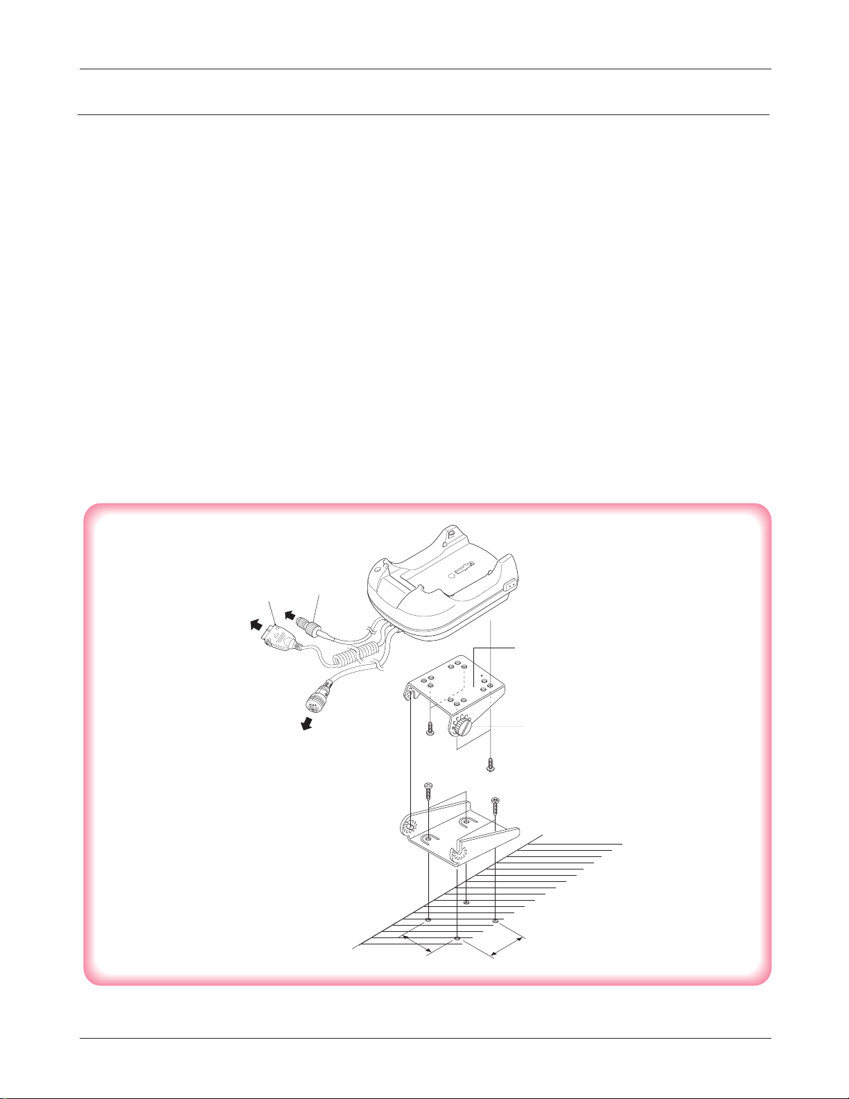
3-3-2 Cradle
1. Choose a location where it is easy to reach and
does not interfere with the driver’s safe
operation of the car.
2. Separate the two halves of the clamshell by
removing the two large slotted screws. See the
figure 3-2.
3. Drill holes and mount the lower half of the
clamshell by using the screws.
4. Place the cradle onto the remaining half of the
clamshell and assemble them by using the
screws.
5. Reassemble the two halves of the clamshell
together. Adjust the mounting angle and tighten
the two slotted screws.
Figure 3-2 Cradle Installation
SCH-3500
MAIN PHONE
ANTENNA
CLAM SHELL
MOUNT UPPER
CLAM SHELL
MOUNT LOWER
CRADLE
FIXED SCREW
CAR
HANDS
FREE BOX
32
32
SAMSUNG Proprietary-Contents may change without notice
3-3
Installation
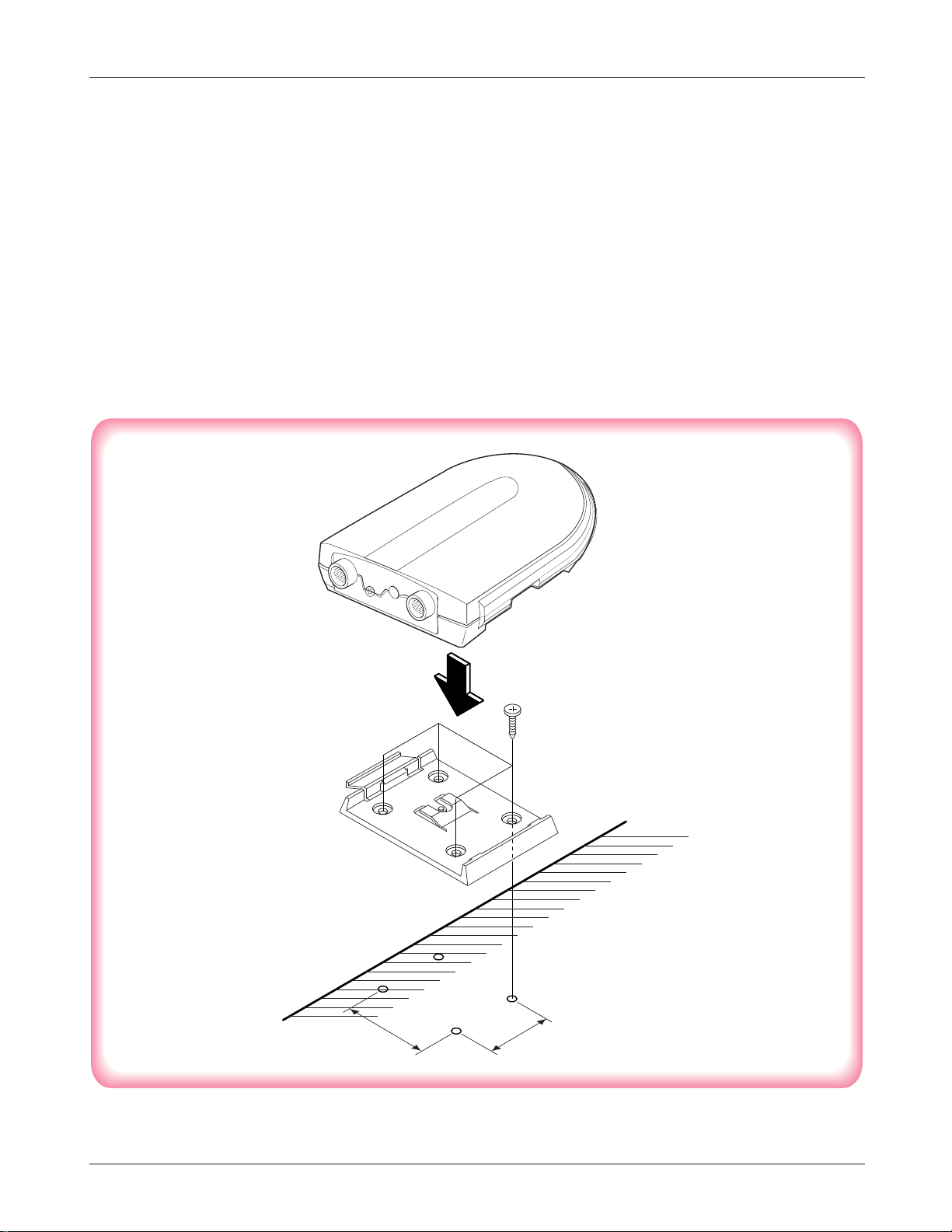
3-3-3 Hands-Free Box
1. Drill holes in a proper location for the handsfree box, attach the mounting bracket by using
the screws. See the figure 3-3.
2. Install the hands-free box into the bracket.
3-3-4 Speaker
1. Install the speaker into the appropriate position.
3-3-5 Hands-Free Microphone
1. It is recommended to install the microphone
where it is 30-45 cm (12-18”) away from the
driver. Choose the location where is least
susceptible to interference caused by external
noise sources, ie, adjacent windows, car audio
speakers, etc. Normal place is the sun visor.
2. Once the microphone has been correctly
positioned, connect the microphone wire to the
MIC jack on the hands-free box.
Figure 3-3 Hands-Free Box Installation
MOUNTING BRACKET
CAR
40
55
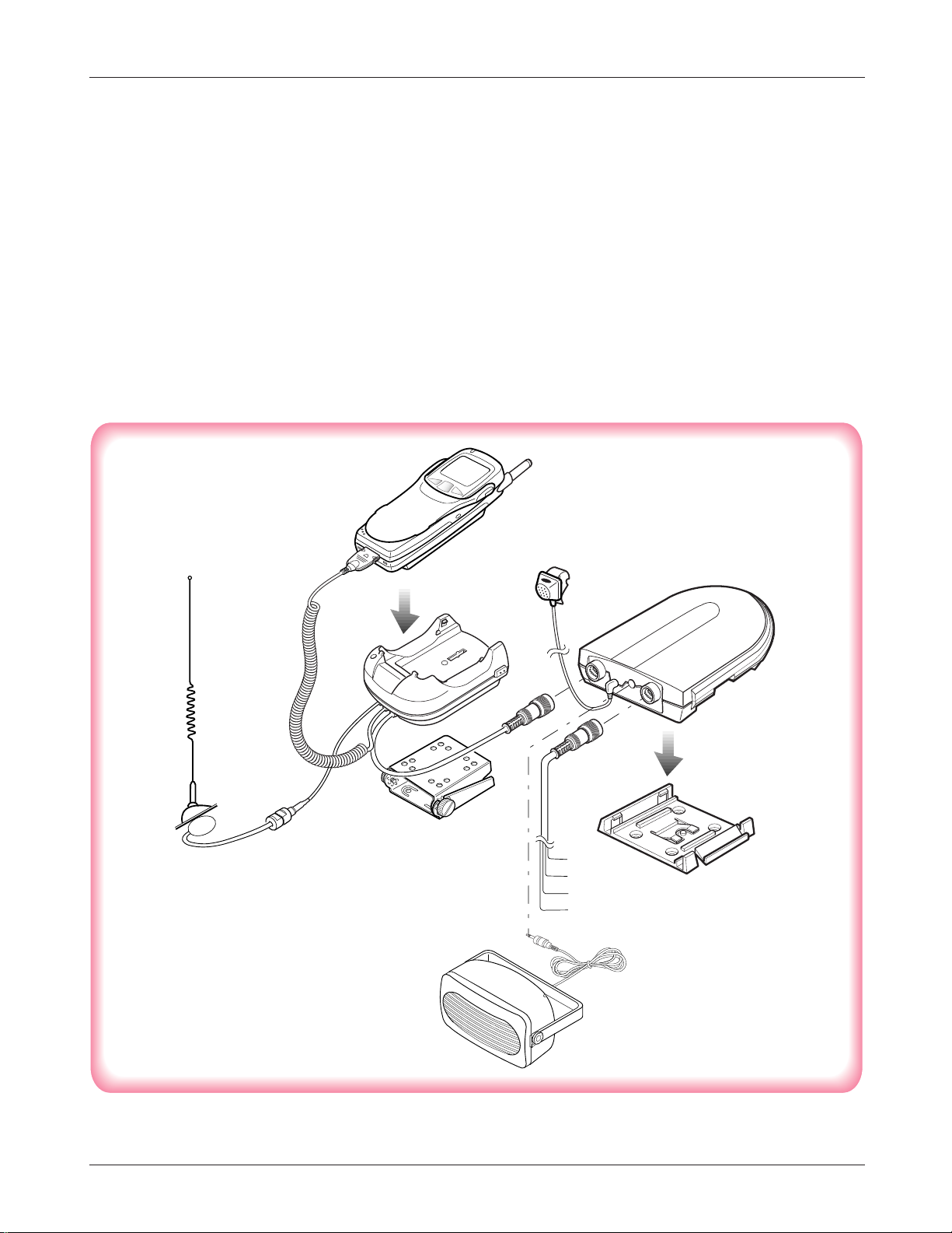
3-3-6 Cables
1. Connect the cradle and the hands-free box with
the data cable. See the figure 3-4.
2. Connect the antenna cable to the RF jack of the
cradle.
3. Connect the red wire to the battery (+) terminal,
black wire to the vehicle chassis, brown wire to
the Car Audio Mute port and orange wire to the
ignition port in the key box of vehicle or battery
(+) terminal.
4. Connect the other end of the power cable to the
PWR jack of the hands-free box.
Notes:
•It is recommended to connect the power cable
directly to the battery to avoid power noise.
•Make sure the connection between the battery (-)
terminal and vehicle chassis is made correctly.
•Make sure the fuse having a proper capacity is
used on the power cable.
•Make sure the cables do not pass over any sharp
metal edge that may damage it.
Figure 3-4 Cable Connections
Red
Black
Brown
Orange
SAMSUNG Proprietary-Contents may change without notice
3-4
Installation
SAMSUNG Proprietary-Contents may change without notice
4-1
4. NAM Programming
NAM features can be programmed as follows:
Notes:
- If you enter the NAM program mode, each item shows the currently stored data. Go to the next item by
pressing OK.
- You can modify the data by entering a new data.
- If you enter a wrong digit, press CLR to delete the last digit. Press and hold CLR to delete all digit.
- To scroll items backwards press the VOLUME button on the left side of the phone.
4-1 Single NAM
4-1-1 General Setup
LCD Display Key in Function
Menu, 6, 0 Select NAM programming
6-digit code Enter random 6 digit code (MSL)
2 Choose ‘General’
Volume „ Electronic Serial Number of the phone is displayed
Volume „ Common Air Interface version is displayed
Volume „
Volume „ Station Class Mark displays the power class, transmission,
slotted class, dual mode.
Lock code, current status is displayed.
4-digit code -to change, enter new code.
OK -stores it.
Slot mode. ‘Yes’ indicates the slot mode.
ˆ or ¤ -changes the status.
OK -store it.
Slot mode index. The higher, the longer sleeping time.
0 ~ 7 -to change, enter new one.
OK -stores it.
Enter Lock
??????
ESN
B0000000
CAI version
1
VOC8/13/EVRC
SO_VOICE_13K
SCM
10101010
Lock Code
0000
Slot Mode
Yes
Slot Index
2
SVC Menui m
1:Phone#
2:General
3:NAM
4-1-3 Setting Up NAM
LCD Display Key in Function
3 Choose ‘NAM’.
IMSI Mobile Country Code, current code is displayed.
Number -to change, enter new one.
OK -stores it.
IMSI Mobile Network Code, current code is displayed.
Number -to change, enter new one.
OK -stores it.
CDMA Access Overload Class, current status is displayed.
Class number -to change, enter new one.
OK -stores it.
CDMA Home system ID, current status is displayed
ˆ or ¤ -change the status
OK -store it.
SAMSUNG Proprietary-Contents may change without notice
4-2
NAM Programming
SVC Menui m
1:Phone#
2:General
3:NAM
IMSI_MCC
310
IMSI_MNC
00
CDMA ACCOLC
0
4-1-2 Phone #
LCD Display Key in Function
1 Choose ‘Phone#’.
Phone number
OK
Mobile ID
OK
SVC Menui m
1:Phone#
2:General
3:NAM
Phone #
1234567890
Mobile ID #
1234567890
CDMA HomeSID
Yes

LCD Display Key in Function
CDMA foreign SID, current status is displayed.
ˆ or ¤ -change the system.
OK -store it.
CDMA foreign NID, current status is displayed.
ˆ or ¤ -change the system
OK -store it.
SID written in the list, current status is displayed.
Number -to change, enter new one.
OK -store it.
NID written in the list, current status is displayed.
Number -to change, enter new one.
OK -store it.
SAMSUNG Proprietary-Contents may change without notice
4-3
NAM Programming
CDMA fSID
Yes
CDMA fNID
Yes
HOME SID
4120
NID
65535
5. Product Support Tools
5-1 General
IMPORTANT INFORMATION
Purpose
The Product Support Tool (PST) offers you the ability to interface with the SAMSUNG DBDM telephone using
a PC. With this tool you can program the phones network system requirements and functionality, swap phone
data, and download software upgrades. This document supports UniPST version x.xx.
NOTE: This software must be executed in the Windows95/98 mode.
EQUIPMENT REQUIRED
Make sure you have the following equipment setup:
1. Minimum PC configuration: 586 CPU, 16MB RAM, Windows95/98, 5MB of disk space free for software
upgrade.
2. PST Software with appropriate cable (DM Cable for SAMSUNG DBDM phone).
3. Serial Port (16550 Serial Interface Card).
4. Power Supply (3.8 V) or Battery.
INSTALLATION
Software
1.Insert the PST floppy disk into drive (A:\).
2.Create an appropriate directory on the C:\ drive for PST software, Execute Setup.exe file,
The installation program creates folder and task bar on the windows95/98 start bar.
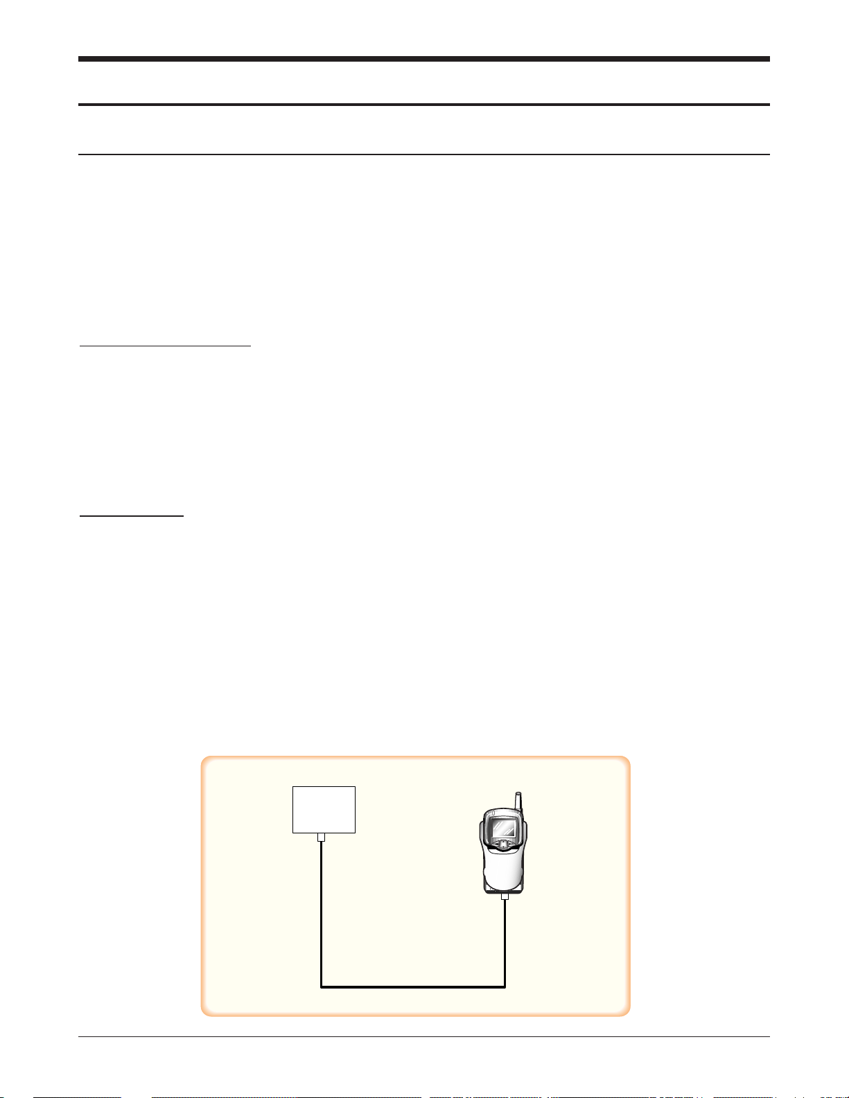
SAMSUNG DBDM Phone
The serial port should be configured to COM1 or COM2.
Use the following procedure to connect the phone, cable, and PC .
Plug the female end of the DM Cable into the 16550 card.
Pull the black rubber connector away from the socket at the base of the phone.
Plug the special connector on the cable into the socket at the base of the phone.
SAMSUNG Proprietary-Contents may change without notice
5-1
PC
Phone
DB Cable
(Parts No.:GH39-30525A)

SAMSUNG Proprietary-Contents may change without notice
5-2
Product Support Tools
5-2. PST (Product Support Tool)
5-2-1 Getting Started
MAIN MENU SCREEN
1. At the Windows95/98, Double Click “UniPst.exe”.
2. The Main Menu Screen will be displayed.
The Main Menu Screen shows the basic tasks that are available.
CAUTION: DO NOT attempt to program phone with a low battery.
PST SETUP
UniPst supports SAMSUNG DBDM portable telephone. You can select serial port COM1 or COM2.
5-2-2 Operation Procedure
Service Programming
The Service Programming screens enable you to set and change the service activation parameters of the
phones. These items can be changed individually or as a group via the “Edit Items” Property Sheet of the PST.
There are several pages on the Service Programming Property Sheet (See below Figure).
Read Data from File
Click “open” icon to select the name of a file whose extension is “mmc”. The values will be read from the
named file, and will initialize the parameter values seen on the Service programming screen
Read Data from Phone
Click Read from the Phone icon to upload the current programmable parameters of the phone. The values are
read from the phone, so the phone must have the power ON and be properly connected to the PST.
NOTE: To actually view the data you need to go to the Edit Items screens.
Edit Items
Click this icon to edit Number Assignment Module (NAM) items or UI items.
There are two types of screens:
1. Parameters associated with a particular Number Assignment Module (NAM)
2. UI items settings
Phone Book
Click this icon to edit Phone Book.
While you edit cell, you can use <Enter> and < UP , DOWN,LEFT,LIGHT Arrow> and <SPACE> key. If you
want to edit phone number or name , you must move rectangle box to cell where you want to edit , Write it
down . if <UP and DOWN Arrow> key is pressed, the cursor moves to next cell or previous cell.

SAMSUNG Proprietary-Contents may change without notice
5-3
Product Support Tools
Save Data to File
Click this icon to save the current parameters to a file. Once you enter a filename, Click <OK> button to write
all current parameters to that file. This way the same information can be downloaded into multiple phones.
Write to Phone
Click this icon to write the selected parameter values to the phone. Writing the selected values to the phone
may take up to a minute.
If there are dependencies in a field you can make all the changes in the proper fields and download the
information all together.
If you intend to use this “Write to Phone” feature, it is recommended that you do a “Read Data from Phone”
first, and then make the changes, so that nothing gets inadvertently overwritten.
NOTE: DO NOT TOUCH THE PHONE WHILE WRITING IS IN PROGRESS.
Software Download and Upgrade Screen
To begin a software upgrade or download, perform the following steps:
1. From the main menu screen choose DOWNLOAD MODE?
Click open icon to choose a BIN file of the new software to be loaded. Choose the appropriate BIN file, then
Click <Open> (see below figure).
2. Click Download? to begin downloading the file. You will notice various messages and a progress bar that
informs the user what percentage of the downloading has already occurred.
3. Click Mode Select box, then Select SERVICE MODE?to return to the Service Mode Screen.
NOTE: DO NOT POWER OFF WHILE THE PHONE IS BEING DOWNLOADED!

6. Circuit Description
6-1 Logic Section
SAMSUNG Proprietary-Contents may change without notice
6-1
6-1-1 Power Supply
With the battery installed on the phone and by
pressing the PWR key, the VBATT and ON_SW
signals will be connected. This will turn on Q905
(2SC4081BR). This in turn will be supplied to
regulators (U905 and U907), thus releasing them
from the shut-down state to output regulated 3.0V.
The VBATT applied to ON_SW will turn on Q907
(DTC144EE) resulting in the signal ON_SW_SENSE
to change state from HIGH to LOW. This will allow
MSM to send out PS_HOLD (logical HIGH) to turn
on Q905 even after the PWR key is released.
The voltage (+3.0VD) from U907 is used in the
digital parts of MSM. The voltage (+3.0VA) from
U905 is used in the analog part.
6-1-2 Logic Part
The Logic part consists of internal CPU of MSM,
Memory and EEPROM. The MSM receives TCXO
and CHIPX8 clock signals from the IFR and controls
the phone during the CDMA and the FM mode. The
major components are as follows:
•CPU : ARM7TDMI Micro-processor
•Memory : U801 (MB84VD21194-85-PBS)
16M Flash ROM, 4M SRAM
•EEPROM : U903 (M24256)
256K Serial EEPROM
CPU
ARM7TDMI microprocessor is used for the main
processing. The CPU controls all the circuitry. For
the CPU clock, 27 MHz resonator is used.
MEMORY (U801)
16M Flash and 4 M SRAM one package is used to
store the terminals programs , the internal flag
information, call processing data, and timer data.
Using the down-loading program, the program can
be changed even after the terminal is fully
assembled.
EEPROM (U903)
One 256 kbit EEPROM is used to store ESN, NAM,
power level, volume level, and telephone number.
KEYPAD
For key recognition, key matrix is setup using
SCAN0-6 of STORE signals and KEY0-3 of input
ports of MSM. Ten LEDs and backlight circuitry are
included in the keypad for easy operation in the
dark.
LCD MODULE
LCD module contains a controller which will
display the information onto the LCD by 8-bit data
from the MSM.

SAMSUNG Proprietary-Contents may change without notice
6-2
Circuit Description
6-1-3 Baseband Part
MOBILE SYSTEM MODEM (MSM)
The MSM equipped with the ARM7TDMI core is an
important component of the CDMA cellular phone.
The MSM comes in a 196 pins BGA package. The
interface block diagram is shown on page 6-3.
MICROPROCESSOR INTERFACE
The interface circuitry consists of reset circuit,
address bus (A0-A19), data bus (AD0-AD15), and
memory controls (ALE, DT_R, HWR/, LWR/,
ROM_CS).
INPUT CLOCK
•CPU clock: 27 MHz
•TXCO(pin L2): 4.92 MHz. This clock signal from
the IFR is the reference clock for the MSM except
in CDMA mode.
•CHIPX8(pin H2) : 9.8304 MHz. The reference clock
used during the CDMA mode.
•SLEEP-XTAL-IN/OUT(pins M10, P12) : 32.768
kHz
IFT/IFR INTERFACE
CDMA, FM Data Interface
•TXIQDATA0-7 (pins L1, J3, K2, K1, J4, H3, J1, J2) :
TX data bus used during both CDMA and FM
mode.
•C_RX_IDATA0-3 (pins G1-G4) and
C_RX_QDATA0-3 (pins F1-F4) : RX data bus used
during CDMA mode.
•FM_RX_IDATA (pin E4) and FM_RX_QDATA (pin
E3) : RX data bus used during FM mode.
Clock
•TX_CLK (pin H1), TX_CLK/(pin H4) : Analog to
Digital Converter (ADC) reference clock used in
TX mode.
•CHIPX8 : ADC reference clock used in CDMA RX
mode.
•FMCLK : Reference clock in FM RX mode.
ADC Interface
ADC_CLK (pin C1), ADC_ENABLE (pin C2) and
ADC_DATA (pin B1) are required to control the
internal ADC in the IFT/IFR.
Data Port Interface
Includes the UART. Also, supports Diagnostic
Monitor (DM) and HP equipment interface.
CODEC Interface
The MSM outputs 2.048 MHz PCM_CLK (pin B11)
and 8 kHz PCM_SYNC (pin C11) to the CODEC
(U902). The voice PCM data from the MSM (U908)
PCM_DIN (pin A12) is compressed into 8 kHz by
QCELP algorithm in the CDMA mode. In FM mode,
the data is processed by D_FM.
RF Interface
TX : TX_AGC_ADJ (pin K3) port is used to control
the TX power level and PA_ON (pin L4) signal is
used to control the power amplifier.
RX : RX_AGC_ADJ (pin M1) port is used to control
the RX gain and TRK_LO_ADJ (pin N3) is used to
compensate the TCXO clock.
General Purpose I/O Register Pins
Input/output ports to control external devices.
Power Down Control
When the IDLE/ signal turns LOW, only the TX
sections will be disabled. If both the IDLE/ and
SLEEP/ changes to LOW, all the pins except for the
TXCO is disabled.
 Loading...