

Page 1
3. Installation
3-1 Installing a Battery Pack
1. To attach the battery pack after charging, align
it with the phone about 1cm (1/2") away from
its place so that the two arrows on the phone
are seen, the battery charge contacts pointing
downward.
2. Slide the battery pack upwards until it clicks
firmly into position. The phone is now ready
to be turned on.
3-2 For Desk Top Use
1. Choose a proper location to install the charger
for desk top use.
2. Plug the power cord of the charger into an
appropriate wall socket. When the power is
connected correctly, the lamps turn on briefly.
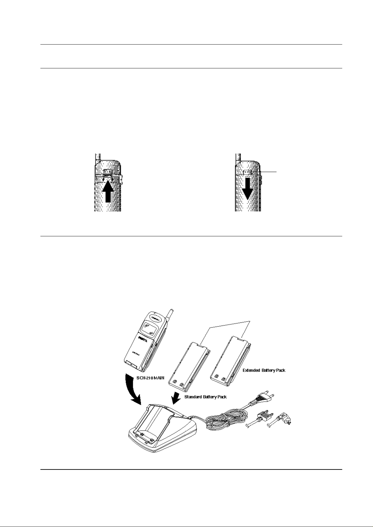
3. To remove the battery pack, release it by
pressing the button on the rear of the phone.
4. Slide the battery pack downward about 1cm
(1/2") and lift it away from the phone.
Press this button to release
the battery pack
3. To charge the battery pack, insert the battery
pack into the rear slot of the charger. The lamp
marked BAT on the front panel of the charger
lights up red.
4. If you do not wish to use the phone while
charging the battery, insert the phone with the
battery pack attached into the front slot of the
charger. The lamp marked PHONE on the
front panel of the charger lights up red.
Figure 3-1 Charging the Phone and Battery
Samsung Electronics - Contents may change without notice. 3-1
Page 2

Installation
Item Model Name Service Part#
Desk Top Rapid Charger DTC58 GH44-40034A
Standard Battery Pack BTL850SB GH43-10104A
Extended Battery Pack BTL1350EB GH43-10103A
SPECIFICATIONS USING “DTC 58”
Product Charging time Stand by time (hours) Talking time (min)
(hours) Digital Analog Digital Analog
Standard Battery Pack (Li-ion: 800mAh) 2 ~ 3 50 ~ 55 10 ~ 12 150 100
Extendard Battery Pack (Li-ion: 1350mAh) 2.5 ~ 3.5 85 ~ 90 16 ~ 18 250 170
3-3 For Mobile Mount
3-3-1 Antenna
1. Choose a proper location to install the
antenna.
The center of the roof top provides the best
performance.
The edge of the rear trunk also provides a
good performance. However, the antenna
should be higher than the roof of the car.
In case of on-glass antenna, you should
align the antenna base with the round plate
to connect the cables correctly.
2. Mount the antenna vertically, connect the
antenna cable.
3. Tighten the antenna nut fully.
3-2 Samsung Electronics - Contents may change without notice.
Page 3

3-3-2 Cradle
Installation
1. Choose a location where it is easy to reach and
does not interfere with the driver's safe
operation of the car.
2. Separate the two halves of the clamshell by
removing the two large slotted screws. See the
figure 3-2.
3. Drill holes and mount the lower half of the
clamshell by using the screws.
4. Place the cradle onto the remaining half of the
clamshell and assemble them by using the
screws.
5. Reassemble the two halves of the clamshell
together. Adjust the mounting angle and
tighten the two slotted screws.
Figure 3-2 Cradle Installation
Samsung Electronics - Contents may change without notice. 3-3
Page 4

Installation
3-3-3 Hands-Free Box
1. Drill holes in a proper location for the handsfree box, attach the mounting bracket by using
the screws. See the figure 3-3.
2. Install the hands-free box into the bracket.
3-3-4 Hands-Free Microphone
1. It is recommended to install the microphone
where it is 30-45 cm (12-18") away from the
driver. Choose the location where is least
susceptible to interference caused by external
noise sources, ie, adjacent windows, radio
speakers, etc. Normal place is the sun visor.
2. Once the microphone has been correctly
positioned, connect the microphone wire to
the MIC jack on the hands-free box.
Figure 3-3 Hands-Free Box Installation
3-4 Samsung Electronics - Contents may change without notice.
Page 5

3-3-5 Cables
Installation
1. Connect the cradle and the hands-free box
with the data cable. See the figure 3-4.
2. Connect the antenna cable to the RF jack of the
cradle.
3. Connect the power cable as follows:
Connect the red wire to the battery (+)
terminal, black wire to the battery (-) terminal.
Then connect the orange wire to the switched
side of the ignition switch, and then connect
the brown wire to the stereo mute wire from
your vehicle stereo.
4. Connect the other end of the power cable to
the PWR jack of the hands-free box.
Notes:
It is recommended to connect the power cable
directly to the battery to avoid power noise.
Make sure the connection, in the vehicle,
between the battery (-) terminal and vehicle
chassis is made correctly.
Make sure the fuse having a proper capacity is
used on the power cable.
Make sure the cables do not pass over any sharp
metal edge that may damage it.
Figure 3-4 Cable Connections
Samsung Electronics - Contents may change without notice. 3-5
Page 6

Installation
3-6 Samsung Electronics - Contents may change without notice.
 Loading...