

Samsung SCH-1500 Service Manual
PORTABLE CELLULAR
TALK END/
123
456
7809
ABC DEF
MNOJKLGHI
PQRS
CLR
OK
MENU
TUV
OPER
WXYZ
TELEPHONE
SCH-1500 Series
Manual
SERVICE
PORTABLE CELLULAR TELEPHONE CONTENTS
1. General Introduction
2. Specification
3. Installation
4. Nam Programming
5. Product Support Tools
6. Circuit Description
7. Test Procedure
8. Trouble Shooting
9. Exploded Views and Parts List
10. PCB Diagrams
11. Electrical Parts List
12. Block & Circuit Diagrams

ELECTRONICS
Samsung Electronics Co.,Ltd.

1. General Introduction
The SCH-1500 DBDM phone functions as both analog phone working in AMPS (Advanced Mobile Phone
Service) mode and digital phone working in PCS (Personal Communication Service) mode.
The following standards and minimum performance standards shall be met or exceeded by each subscriber
unit.
Air Interface
The Subscriber Unit shall be Dual mode and Dual band in compliance with ANSI J-STD-008 and TIA/EIA IS95A(Analog).
ANSI J-STD-008 : Personal Station-Base Station Compatibility Requirements for 1.8 to 2.0 GHz CDMA PCS.
ANSI J-STD-018 : Recommended Minimum Performance Requirements for 1.8 to 2.0 GHz CDMA Personal
Stations.
CDG Ref. Document #27 : High Rate Speech Service Option for Wideband Spread Spectrum System.
TIA/EIA IS-96A : Speech Service Option 1 Standard for Dual mode Wideband Spread Spectrum Cellular
Systems.
TIA/EIA IS-125 : Recommended Minimum Performance standards for Digital Cellular Wideband Spread
Spectrum Speech Service Option1.
TIA/EIA IS-126-A : Mobile Station Loop back Service Option standard.
CDMA Receiver/Transmitter Specifications and Requirements
The Subscriber Unit shall comply with ANSI J-STD-008 and meet or exceed TIA/EIA IS-98A. The Subscriber
Unit shall comply with Personal Station Class II.
Analog Receiver/Transmitter Specifications and Requirements
The Subscriber Unit shall comply with TIA/EIA IS-95A and meet or exceed TIA/EIA IS-95. The Subscriber Unit
shall comply with Mobile Station Power Class III (600mW).
Samsung Electronics 1-1

General Introduction
Memo
1-2 Samsung Electronics

2. Specification
2-1 General
Frequency Range PCS Mode AMPS Mode
Transmitter : 1850 ~ 1910 MHz 824 ~ 849 MHz
Receiver : 1930 ~ 1990 MHz 869 ~ 894 MHz
Channel Spacing : 1.25 MHz 30 kHz
Number of Channels : 1200 832
Duplex Spacing : 80 MHz 45 MHz
Frequency Stability : (FRX - 80MHz) ± 150Hz ± 2.5 ppm
Operating Temperature : -30 oC ~ 60 oC
Operating Voltage
HHP : 7.2V DC (± 10%)
Hands-free : 13.7V DC (± 10%)
Size and Weight
including standard battery : 14.6 x 5.4 x 2.5 cm, 191 cc, 220 g (7.7 ounces)
including extended-life battery : 14.6 x 5.4 x 3.35 cm, 250 cc, 226 g (7.9 ounces)
Samsung Electronics 2-1

Specification
2-2 AMPS Mode
TRANSMITTER
RF output power : 0.6 W (+2/ - 4 dB)
Carrier ON/OFF Conditions
ÒONÓ Condition : within ± 3 dB of specification output (in 2mS)
ÒOFFÓ Condition : below - 60 dBm (in 2mS)
Compressor
Compression Rate : 2:1
Attack Time : 3 mS
Recovery Time : 13.5 mS
Reference Input : Input level for producing a nominal ± 2.9 kHz peak
frequency deviation of transmitted carrier
Preamphasis : 6 dB/OCT within 0.3 ~ 3 kHz
Maximum Frequency Deviation
F3 of G3 : ± 12 kHz (± 10 %)
Supervisory Audio Tone : ± 2 kHz (± 10 %)
Signaling Tone : ± 8 kHz (± 10 %)
Wideband Data : ± 8kHz (± 10 %)
Post Deviation Limiter Filter
3.0 kHz ~ 5.9 kHz : above 40LOG (F/3000) dB
5.9 kHz ~ 6.1 kHz : above 35 dB
6.1 kHz ~ 15 kHz : above 40 LOG (F/3000) dB
Over 15 kHz : above 28 dB
Spectrum Noise Suppression
For All Modulation
f0+ 20 kHz ~ f0+ 45 kHz : above 26 dB
For Modulation by Voice and SAT
f0+ 45 kHz : above 63 + 10LOG (Py) dB
For Modulation by WBD (without SAT) and ST (with SAT)
f0+ 45 kHz ~ f0+ 60 kHz : above 45 dB
f0+ 60 kHz ~ f0+ 90 kHz : above 65 dB
f0+ 90 kHz ~ 2f
0
: above 63 + 10LOG (Py) dB
(where f0= carrier frequency,
Py = mean output power in watts)
Harmonic and Conducted Spurious Emissions : above 43 + 10 LOG (Py) dB
2-2 Samsung Electronics

Specification
RECEIVER
DE-Emphasis : -6 dB/OCT within 0.3 ~ 3 kHz
Expander
Expansion Rate : 1:2
Attack Time : within 3 mS
Recovery Time : within 13.5 mS
Reference Input : Output level to a 1000 Hz tone from a carrier within ±
2.9 kHz peak frequency deviation
Sensitivity : 12 dB SINAD/-116 dBm
Intermodulation Spurious Response Attenuation : above 65 dB
RSSI Range : above 60 dB
Protection Against Spurious Response Interference : above 60 dB
In Band Conducted Spurious Emissions
Transmit Band : below -60 dBm
Receive Band : below -80 dBm
Out of Band Conducted Spurious Emissions : below - 47 dBm
Radiated Spurious Emissions
Frequency Range Maximum Allowable EIRP
25 ~ 70 MHz -45 dBm
70 ~ 130 MHz -41 dBm
130 ~ 174 MHz -41 ~ -32 dBm
174 ~ 260 MHz -32 dBm
260 ~ 470 MHz -32 ~ -26 dBm
470 ~ 1 GHz -21 dBm
Samsung Electronics 2-3

Specification
2-3 PCS Mode
TRANSMITTER
Waveform Quality : 0.944 or more
Open loop Power Control Range
-25 dBm : -60.5 dBm ~ 41.5 dBm
-65 dBm : -20.5 dBm ~ -1.5 dBm
-104 dBm : +15.0 dBm ~ +30.0 dBm
Minimum Tx Power Control : -50 dBm below
Closed Loop Power Control Range : ±24 dB
Maximum RF Output Power : 200 mW (+23 dBm)
Occupied Bandwidth : 1.23 MHz
Conducted Spurious Emissions @ 1.25 MHz : -42 dBc/30 KHz
RECEIVER
Rx Sensitivity and Dynamic Range : -104 dBm, FER=0.5% or less
(Rate Set 1) : -25 dBm, FER=0.5% or less
Conducted Spurious Emission
1930 ~ 1990 MHz : <-81 dBm
1850 ~ 1910 MHz : <-61 dBm
All Other Frequencies : <-47 dBm
Single Tone Desensitization : lower than 1%
Rx power = -101 dBm
Tone power = -30 dBm
Tone offset from carrier = ±1.25 MHz
Intermodulation Spurious Response Attenuation : lower than 1%
Rx power = -101 dBm
Tone power 1 = -43 dBm
Tone power 2 = -43 dBm
Tone 1 offset from carrier = ±1.25 MHz
Tone 2 offset from carrier = ±2.05 MHz
2-4 Samsung Electronics

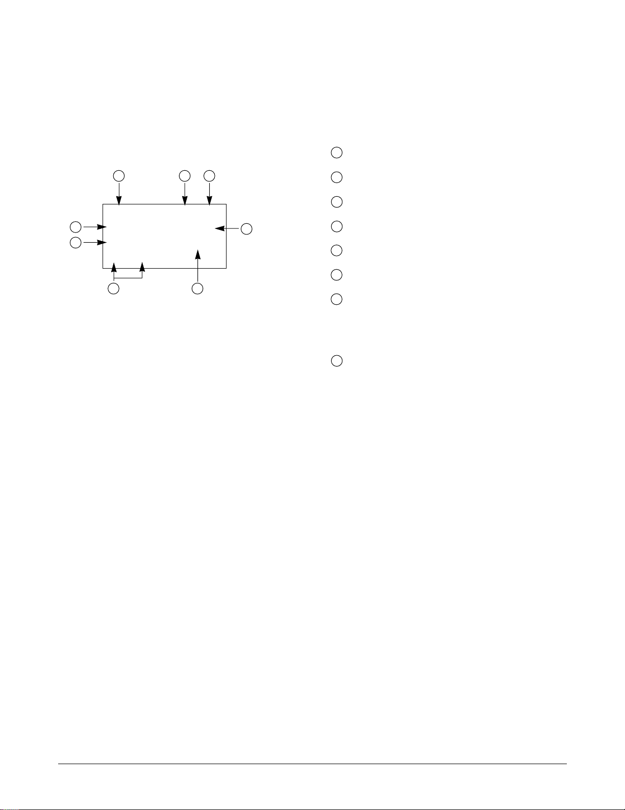
2-4 PCS Debug Display Information
To select debug display mode : Press [MENU] + [8] + [0], and press [0] + [4] + [0] + [7] + [9] + [3] or
press [0] + [0] + [0] + [0] + [0] + [0].
Specification
IN IDLE MODE
1
2 3
SIDxxxxx SIx x
4
7
T - xx Dxxx - xx
Pxxx CHxxxx
xx xx
12
IN CONVERSATION MODE
9
5
10 11
TVx RVx xx x
T - xx Dxxx - xx
Pxxx CHxxxx
xx xx
1 Sxxxxx : SID (System Identification) toggle
Nxxxxx : NID (Network Identification) toggle
2 SIx : Slot cycle index (lowest between the system
and the phone will be used)
1. SI0 : Slot Index 0
6
8
3 Handset Status : 0 - NO SVC
4 T-xx : Tx adjust, Value ranges from +63~0~63dB
3
5 Dxxx : Sector power in dBm
6 -xx : ec/lo
7 Pxxx : PN offset
2. SI1 : Slot Index 1
3. SI2 : Slot Index 2
1 - Synchronization
2 - Paging (Idle)
3 - Reg. Access state
4 - Traffic Initialization
5 - Waiting for order
6 - Waiting for answer
7 - Conversation state
8 - Exit
12
8 CHxxxx : Channel number
9 TV : Tx vocoder rate (8 is full rate, 1 is 1/8th rate)
10 RV : Rx vocoder rate (8 is full rate, 1 is 1/8th rate)
11 xx : Walsh code used in traffic channel
12 System acquisition state
Samsung Electronics 2-5
Specification
2-5 AMPS Debug Display Information
To select debug display mode : Press [MENU] + [8] + [0], and press [0] + [4] + [0] + [7] + [9] + [3] or
press [0] + [0] + [0] + [0] + [0] + [0].
1 SIDxxxxx : AMPS Home System ID
1
7 4
2 PWRx : Power Level 0 ~ 7
3 SATx : Supervisory Audio Tone code (0 ~ 3)
SIDxxxxx x x
2
3
PWRx RSSIxxx
SATx CHxxxx
5
xx xx
8
6
4 x (Using Frequency Band) : A Band or B Band
5 RSSIxxx : RSSI value
6 CHxxx : Using Channel
7 Handset Status : 1 - Initialization state
2 - Idle state
3 - System Access state
4 - Voice channel state
8 System acquisition state
2-6 Samsung Electronics

3. Installation
SCH-1500 MAIN
STANDARD
BATTERY
PACK : BTL859S
EXTENDED
BATTERY PACK
: BTL1359L
DTC : DTC59
Press this button to release
the battery pack.
3-1 Installing a Battery Pack
1. To attach the battery pack after charging, align it
with the phone about 1cm (1/2Ó) away from its
place so that the two arrows on the phone are
seen, the battery charge contacts pointing
downward.
2. Slide the battery pack upwards until it clicks
firmly into position. The phone is now ready to
be turned on.
3-2 For Desk Top Use
1. Choose a proper location to install the charger
for desk top use.
2. Plug the power cord of the charger into an
appropriate wall socket. When the power is
connected correctly, the lamps turn on briefly.
3. To remove the battery pack, release it by
pressing the button on the rear of the phone.
4. Slide the battery pack downward about 1cm
(1/2Ó) and lift it away from the phone.
3. To charge the battery pack, insert the battery
pack into the rear slot of the charger. The lamp
marked BAT on the front panel of the charger
lights up red.
4. If you do not wish to use the phone while
charging the battery, insert the phone with the
battery pack attached into the front slot of the
charger. The lamp marked PHONE on the front
panel of the charger lights up red.
Specifications using DTC
Battery Type Standard Battery Extended battery
(Li-Ion, 850mAH) (Li-Ion, 1350mAH)
Charging Time 3 hours 5 hours
SEC. code GH43-10114A GH43-10113A
Figure 3-1 Charging the Phone and Battery
Samsung Electronics 3-1
Installation
HHP ANTENNA
CLAM SHELL
MOUNT UPPER
CLAM SHELL
MOUNT LOWER
CRADLE
FIXED SCREW
CAR
HANDS
FREE BOX
56
40
3-3 For Mobile Mount
3-3-1 Antenna
1. Choose a proper location to install the antenna.
¥The center of the roof top provides the best
performance.
¥The edge of the rear trunk also provides a
good performance. However, the antenna
should be higher than the roof of the car.
¥In case of on-glass antenna, you should align
the antenna base with the round plate to
connect the cables correctly.
2. Mount the antenna vertically, connect the
antenna cable.
3. Tighten the antenna nut fully.
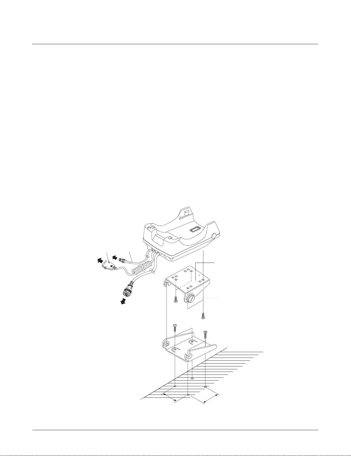
3-3-2 Cradle
1. Choose a location where it is easy to reach and
does not interfere with the driverÕs safe
operation of the car.
2. Separate the two halves of the clamshell by
removing the two large slotted screws. See the
figure 3-2.
3. Drill holes and mount the lower half of the
clamshell by using the screws.
4. Place the cradle onto the remaining half of the
clamshell and assemble them by using the
screws.
5. Reassemble the two halves of the clamshell
together. Adjust the mounting angle and tighten
the two slotted screws.
Figure 3-2 Cradle Installation
3-2 Samsung Electronics
Installation
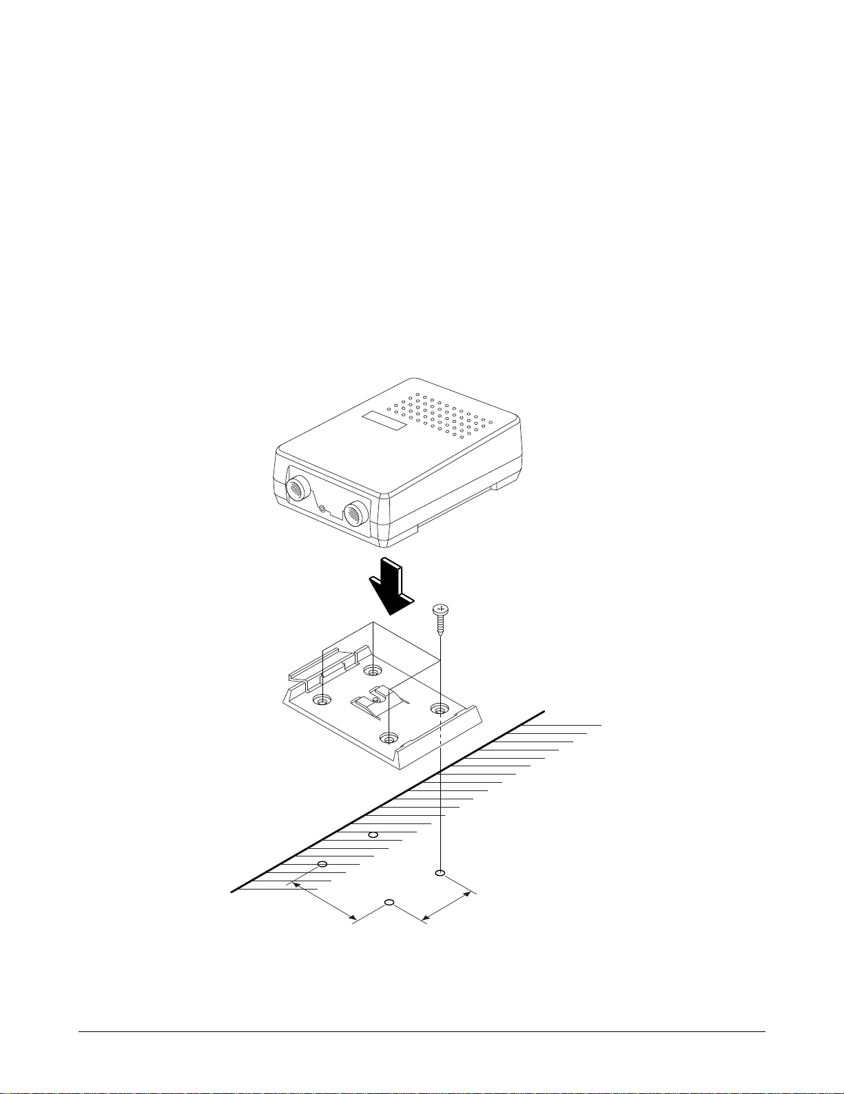
MOUNTING BRACKET
56
40
3-3-3 Hands-Free Box
1. Drill holes in a proper location for the handsfree box, attach the mounting bracket by using
the screws. See the figure 3-3.
2. Install the hands-free box into the bracket.
3-3-4 Hands-Free Microphone
1. It is recommended to install the microphone
where it is 30-45 cm (12-18Ó) away from the
driver. Choose the location where is least
susceptible to interference caused by external
noise sources, ie, adjacent windows, radio
speakers, etc. Normal place is the sun visor.
2. Once the microphone has been correctly
positioned, connect the microphone wire to the
MIC jack on the hands-free box.
Figure 3-3 Hands-Free Box Installation
Samsung Electronics 3-3
Installation
1
ABC
DEF
GHI
PQRS
TUV
WXYZ
OPER
JKL
MNO
2
3
4
5
6
7
8
CLR
OK
MENU
9
*
0
#
TALK
END/
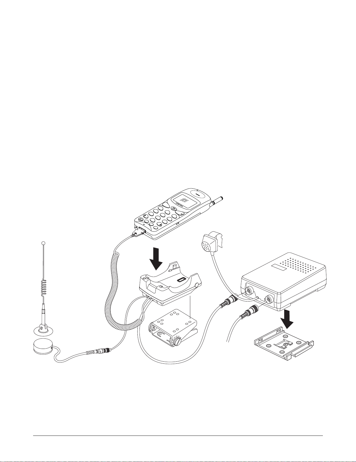
3-3-5 Cables
1. Connect the cradle and the hands-free box with
the data cable. See the figure 3-4.
2. Connect the antenna cable to the RF jack of the
cradle.
3. Connect one of the power cable to the battery or
ignition terminal. Connect the red wire to the
battery (+) terminal, black wire to the vehicle
chassis. Then connect the battery (-) terminal to
the vehicle chassis.
4. Connect the other end of the power cable to the
PWR jack of the hands-free box.
Notes:
¥It is recommended to connect the power cable
directly to the battery to avoid power noise.
¥Make sure the connection between the battery (-)
terminal and vehicle chassis is made correctly.
¥Make sure the fuse having a proper capacity is
used on the power cable.
¥Make sure the cables do not pass over any sharp
metal edge that may damage it.
Figure 3-4 Cable Connections
3-4 Samsung Electronics

4. NAM Programming
NAM features can be programmed as follows:
Notes:
- If you enter the NAM program mode, each item shows the currently stored data. Go to the next item by
pressing OK.
- You can modify the data by entering a new data.
- If you enter a wrong digit, press CLR to delete the last digit. Press and hold CLR to delete all digit.
- To scroll items backwards press the VOLUME button on the left side of the phone.
4-1 Single NAM
4-1-1 General Setup
LCD Display Key in Function
Menu, 5, 0 Select NAM programming
Enter Lock
??????
SVC Menumi
1:Phone#
2:General
3:NAM
ESN
B0000000
CAI version
1
SCM
10101010
Lock Code
0000
Slot Mode
No
6-digit code Enter random 6 digit code (MSL)
2 Choose ÔGENERALÕ
Volume ¹ Electronic Serial Number of the phone is displayed
Volume ¹ Common Air Interface version is displayed
Volume ¹ Station Class Mark displays the power class, transmission,
slotted class, dual mode.
Lock code, current status is displayed.
4-digit code -to change, enter new code.
OK -stores it.
Slot mode. ÔYesÕ indicates the slot mode.
m or i -changes the status.
OK -store it.
Slot Index
2
Samsung Electronics 4-1
0 ~ 7 -to change, enter new one.
OK -stores it.
Slot mode index. The higher, the longer sleeping time.

NAM Programming
4-1-2 Phone #
LCD Display Key in Function
SVC Menumi
1:Phone#
2:General
3:NAM
Phone #
1234567890
Mobile ID #
1234567890
1 Choose ÔPhone#Õ
Phone number
OK
Mobile ID
OK
4-1-3 Setting Up NAM
LCD Display Key in Function
SVC Menumi
1:Phone#
2:General
3:NAM
Volume ¹ NAM Programming Menu is displayed.
SVC Menumi
3:NAM
IMSI_MCC
310
IMSI_MNC
00
CDMA ACCOLC
0
4-2 Samsung Electronics
3 Choose ÔSetup NAMÕ.
IMSI Mobile Country Code, current code is displayed.
Number -to change, enter new one.
OK -stores it.
IMSI Mobile Network Code, current code is displayed.
Number -to change, enter new one.
OK -stores it.
CDMA Access Overload Class, current status is displayed.
Class number -to change, enter new one.
OK -stores it.

LCD Display Key in Function
NAM Programming
CDMA Home SID
Yes
CDMA fSID
Yes
CDMA fNID
Yes
HOME SID
1700
NID
1
CDMA Home system ID, current status is displayed
m or i -changes the status
OK -stores it.
CDMA foreign SID, current status is displayed.
m or i -changes the system.
OK -stores it.
CDMA foreign NID, current status is displayed.
m or i -changes the system
OK -stores it.
SID written in the list, current status is displayed.
Number -to change, enter new one.
OK -store it.
NID written in the list, current status is displayed.
Number -to change, enter new one.
OK -stores it.
Samsung Electronics 4-3

NAM Programming
4-2 Dual NAM
4-2-1 General Setup
LCD Display Key in Function
Menu, 5, 0 Select NAM programming
Enter Lock
??????
SVC Menumi
1:Phone#
2:General
3:NAM1
4:NAM2
ESN
B0000000
CAI version
1
SCM
10101010
Lock Code
0000
6-digit code Enter random 6 digit code (MSL)
2 Choose ÔGENERALÕ
Volume ¹ Electronic Serial Number of the phone is displayed
Volume ¹ Common Air Interface version is displayed
Volume ¹ Station Class Mark displays the power class, transmission,
slotted class, dual mode.
Lock code, current status is displayed.
4-digit code -to change, enter new code.
OK -stores it.
Slot Mode
No
Slot Index
2
4-4 Samsung Electronics
m or i -changes the status.
OK -store it.
0 ~ 7 -to change, enter new one.
OK -stores it.
Slot mode. ÔYesÕ indicates the slot mode.
Slot mode index. The higher, the longer sleeping time.

4-2-2 Phone # NAM1
LCD Display Key in Function
NAM Programming
SVC Menumi
1:Phone#
2:General
3:NAM1
4:NAM2
Phone #
1:NAM1
2:NAM2
Phone #
1234567890
Mobile ID #
1234567890
4-2-3 Phone # NAM2
1 Choose ÔPhone#Õ
1 Choose ÔNAM1Õ
Phone number
OK
Mobile ID
OK
LCD Display Key in Function
SVC Menumi
1:Phone#
2:General
3:NAM1
4:NAM2
Phone #
1:NAM1
2:NAM2
Phone #
1234567890
Mobile ID #
1234567890
1 Choose ÔPhone#Õ.
2 Choose ÔNAM2Õ.
Phone number
OK
Mobile ID
OK
Samsung Electronics 4-5

NAM Programming
4-2-4 Setting Up NAM1
LCD Display Key in Function
SVC Menumi
1:Phone#
2:General
3:NAM1
4:NAM2
SVC Menumi
3:NAM1
IMSI_MCC
310
IMSI_MNC
00
CDMA ACCOLC
0
Volume ¹ NAM Programming Menu is displayed.
3 Choose ÔSetup NAM1Õ.
IMSI Mobile Country Code, current code is displayed.
Number -to change, enter new one.
OK -stores it.
IMSI Mobile Network Code, current code is displayed.
Number -to change, enter new one.
OK -stores it.
CDMA Access Overload Class, current status is displayed.
Class number -to change, enter new one.
OK -stores it.
CDMA Home SID
Yes
CDMA fSID
Yes
CDMA fNID
Yes
HOME SID
1700
NID
1
CDMA Home system ID, current status is displayed
m or i -changes the status
OK -stores it.
CDMA foreign SID, current status is displayed.
m or i -changes the system.
OK -stores it.
CDMA foreign NID, current status is displayed.
m or i -changes the system
OK -stores it.
SID written in the list, current status is displayed.
Number -to change, enter new one.
OK -store it.
NID written in the list, current status is displayed.
Number -to change, enter new one.
OK -stores it.
4-6 Samsung Electronics

4-2-5 Setting Up NAM2
LCD Display Key in Function
NAM Programming
SVC Menumi
1:Phone#
2:General
3:NAM1
4:NAM2
SVC Menumi
4: NAM2
IMSI_MCC
310
IMSI_MNC
00
CDMA ACCOLC
0
Volume ¹ NAM Programming Menu is displayed.
4 Choose ÔSetup NAM2Õ.
IMSI Mobile Country Code, current code is displayed.
Number -to change, enter new one.
OK -stores it.
IMSI Mobile Network Code, current code is displayed.
Number -to change, enter new one.
OK -stores it.
CDMA Access Overload Class, current status is displayed.
Class number -to change, enter new one.
OK -stores it.
CDMA Home SID
Yes
CDMA fSID
Yes
CDMA fNID
Yes
HOME SID
1700
NID
1
CDMA Home system ID, current status is displayed
m or i -changes the status
OK -stores it.
CDMA foreign SID, current status is displayed.
m or i -changes the system.
OK -stores it.
CDMA foreign NID, current status is displayed.
m or i -changes the system
OK -stores it.
SID written in the list, current status is displayed.
Number -to change, enter new one.
OK -store it.
NID written in the list, current status is displayed.
Number -to change, enter new one.
OK -stores it.
Samsung Electronics 4-7

NAM Programming
Memo
4-8 Samsung Electronics

5. Product Support Tools
5-1 General
These tools enable you to edit or transfer all the EEPROM data of SCH-1500 DBDM phone.
Equipment Required
¥ IBM compatible PC (above 386, 33MHz, 8MB
RAM, DOS 5.0, 500K of memory free to execute
program, and 1MB of disk space free for software
upgrade.)
¥ SCH-1500 DM cable
¥ SCH-1500 Battery
Connection
Connect the test jig to COM1 port on the PC and
connect the interface cable of the test jig to the
phone.
Caution : When you use the PST program with a
notebook PC, you might encounter some problems.
Check your serial port setup in your notebook PC
(see your notebook PC manual).
Software Installation
1. Insert the PST floppy disk into drive (A:).
2. Create an appropriate directory to the drive (C:)
for PST software.
3. Copy all files of the drive (A:) to the directory
you made.
4. Execute PSTxx.EXE to run the PST program.
Note : There are three executable files in the new
directory you made:
PSTxx.EXE: PST program where xx is the PST
version number.
DonÕt worry about the serial port setup when you
use a desktop PC.
Samsung Electronics 5-1

Product Support Tolls
5-2 Product Support Tool (PST)
The Product Support Tool(PST) offers you the
ability to interface with the SCH-1500 DBDM phone
using a personal computer. You can program the
phone, swap phone data, and download software
upgrades.
Notes :
¥ This software is made to be executed on the MS-
DOS, not on the DOS mode within Windows95. If
this software is executed on Windows 95 by
mistake, it may work abnormally and damage the
phone especially while downloading. Please
check the mode you are using.
¥ You can transfer EEPROM data one unit at a time.
¥ It is illegal to copy to several units.
5-2-1 Getting Started
MAIN MENU SCREEN
1. At the DOS prompt, type ÒPSTxxÓ where xx is
the release version.
2. The Main Menu screen is displayed.
Notes :
¥ The Main Menu screen shows the basic tasks that
are available.
¥ Move the cursor through the menu choices and
press <Enter> key to select a task.
EXITING THE PROGRAM
1. Press <Esc> key until you find the Main Menu
screen.
2. Select the ÒQUITÓ option on the Main Menu or
press <Alt-X> key, and the PST program is over.
EDITING FIELDS
Once you are in a particular screen, you may want
to change a value of any field. A highlighted cursor
can be moved to each editable field by using the
arrow keys. A field can only be edited if the cursor
is on that field (that is, if the field is highlighted.)
1. Begin the editing process by pressing <Enter>
key.
2. To accept the new value, press <Enter> key. To
about edit mode and return to the old value,
press <Esc> key.
3. The value of some field that is fixed types will be
changed by just pressing <Enter> key.
See table 5-1 for the list of editing keys.
5-2-2 Operation Procedure
SERVICE PROGRAMMING
The Service Programming screens enable you to set
and change the service parameters of the phones,
read and write to internal phone book, and transfer
phone book data to other phone. There five options
listed on the Service Programming Main Menu.
The parameter modification is done on the ÒEdit
ParametersÓ screens. The variables found on those
screens can be preset from a phone or a previously
saved file. Select ÒRead Data from FileÓ or ÒRead
Data from PhoneÓ to preset the values.
READ DATA FROM FILE
Use this command to enter the name of a file whose
extension is ÒmmcÓ. The values read from the
named file will initialize the parameter values seen
on the ÒEdit Parameters.Ó
5-2 Samsung Electronics

Product Support Tolls
READ DATA FROM PHONE
Use this command to replace the current
programmable parameter values with the values
that are currently programmed into the phone.
The values are read from the phone that must be
properly connected to the PST with power on.
EDIT PARAMETERS
Use this command to edit Number Assignment
Module (NAM) items and User Preference (U1)
items
There are five screens.
1. General Settings: some writable, some read only.
2. Parameters associated with NAM 1.
3. Parameters associated with NAM 2.
4. First User Preferences.
5. Second User Preferences.
Function Keys
SAVE DATA TO FILE
Use this command to save the current parameters in
a file. Once you enter a filename, press <Enter> key
to write all current parameters to the file.
WRITE ALL TO PHONE
Use this command to write the changed parameter
values to the phone.
Writing the changed values to the phone may take
up to a minute.
Notes :
¥ Some items have dependencies on other items,
and they will be written to the phone together.
¥ If you intend to use this ÒWrite All to PhoneÓ
feature, it is recommended that you do a ÒRead
Data from PhoneÓ first, and then make the
changes, so that nothing gets inadvertently
overwritten.
Esc : Save and Exit
F1 : Displays help message about a selected field.
F6 : Takes you to the General parameters screen.
F7 : Takes you to the NAM 1 parameters screen.
F8 : Takes you to the NAM 2 parameters screen.
F9 : Takes you to the first UI preferences.
F10 : Takes you to the second UI preferences.
Valid & Invalid Data
Upon startup, all items are initialized ÒinvalidÓ.
All fields display the question marks instead of
data. After reading from a phone or a file, if the
question marks still show in a field, then that item
has never been written to the phone or saved to the
file.
5-3Samsung Electronics

Product Support Tolls
SOFTWARE DOWNLOADER
Use this screen to download new software to the
phone. The various windows are displayed to
inform the user of the phone data and the progress
of download.
The software downloader task of the PST is
responsible for downloading a BIN file into the
flash memory on the phone. It verifies that the
given BIN file is compatible with the target phone,
and performs all the protocol necessary to
successfully download the file.
To begin a software downloader, use the following
procedure.
1. Press <F4> key to choose a BIN file of the new
software to be loaded into the phone. An Edit
box will pop up asking for BIN file name. Enter
full file name or press <Enter> key to see the
lists of BIN files in the current directory. Using
the arrow key, choose the appropriate BIN file,
then press <Enter> key.
SETUP
You can setup SCH-1500 only. Use this screen to
choose com.port. you want to setup.
Function keys
SPACE : Scroll through menu.
ENTER : Accepts the phone type chosen.
ESC and ALT-x : Cancel operation and returns to
Main Menu.
QUIT
You can exit the PST program.
2. Press <F8> key to change the mode of the phone
from hands-free mode to DM offline mode. This
function is to view the software and hardware
version of the phone. By setting the phone to
DM offline mode, the upper left window should
display the phone's data. If the phone fails to
change mode, an error sound and message will
occur. In that case, please check the power, link,
and COM port configuration.
3. Press <ALT-D> key to begin download. Various
messages and progress bar will inform the user
of the progress of the download.
Caution : DO NOT REMOVE POWER WHILE THE
PHONE IS BEING DOWNLOADED !
4. Press <Esc> key to return to Main Menu.
5-4 Samsung Electronics

6. Circuit Description
6-1 Logic Section
6-1-1 Power Supply
With the battery installed on the phone and by
pressing the PWR key, the VBATT and ON_SW
signals will be connected. This will turn on Q110
(2SC4081BR) and will drive DC-DC converter
(U130) to output 5.2V. This in turn will be supplied
to regulators (U110 and U120), thus releasing them
from the shut-down state to output regulated 3.3V.
The VBATT applied to ON_SW will turn on Q111
(DTC144EE) resulting in the signal ON_SW_SENSE
to change state from HIGH to LOW. This will allow
MSM to send out PS_HOLD (logical HIGH) to turn
on Q110 even after the PWR key is released.
The voltage (+3.3VD) from U120 is used in the
digital parts of MSM and BBA. The voltage
(+3.3VA) from U110 is used in the analog part of
BBA and Audio circuit.
CPU
INTEL 80186 CMOS type 16-bit microprocessor is
used for the main processing. The CPU controls all
the circuitry. For the CPU clock, 27MHz resonator is
used.
FLASH ROM (U106)
One 8 MBIT FROM is used to store the terminal's
program. Using the down-loading program, the
program can be changed even after the terminal is
fully assembled.
SRAM (U107)
One 2 MBIT SRAM is used to store the internal flag
information, call processing data, and timer data.
6-1-2 Logic Part
The Logic part consists of internal CPU of MSM,
RAM, ROM and EEPROM. The MSM receives
TCXO and CHIPX8 clock signals from the BBA and
controls the phone during the CDMA and the FM
mode. The major components are as follows:
¥CPU : INTEL 80186 core
¥FROM : U126 (MBM29LV800T) - 8MBIT
FLASH ROM
¥SRAM : U127 (KM68U2000LTGI) - 2MBIT
STATIC RAM
¥EEPROM : U113 (AT24C128W) - 128KBIT
SERIAL EEPROM
EEPROM (U108)
One 128 KBIT EEPROM is used to store ESN, NAM,
power level, volume level, and telephone number.
KEYPAD
For key recognition, key matrix is setup using
SCAN0-6 of STORE signals and KEY0-3 of input
ports of MSM. Eight LEDs and backlight circuitry
are included in the keypad for easy operation in the
dark.
LCD MODULE
LCD module contains a controller which will
display the information onto the LCD by 8-bit data
from the MSM. It also consists a DC-DC converter
to supply -3.5V for fine view angle and LCD
reflector to improve the display efficiency.
Samsung Electronics 6-1

Circuit Description
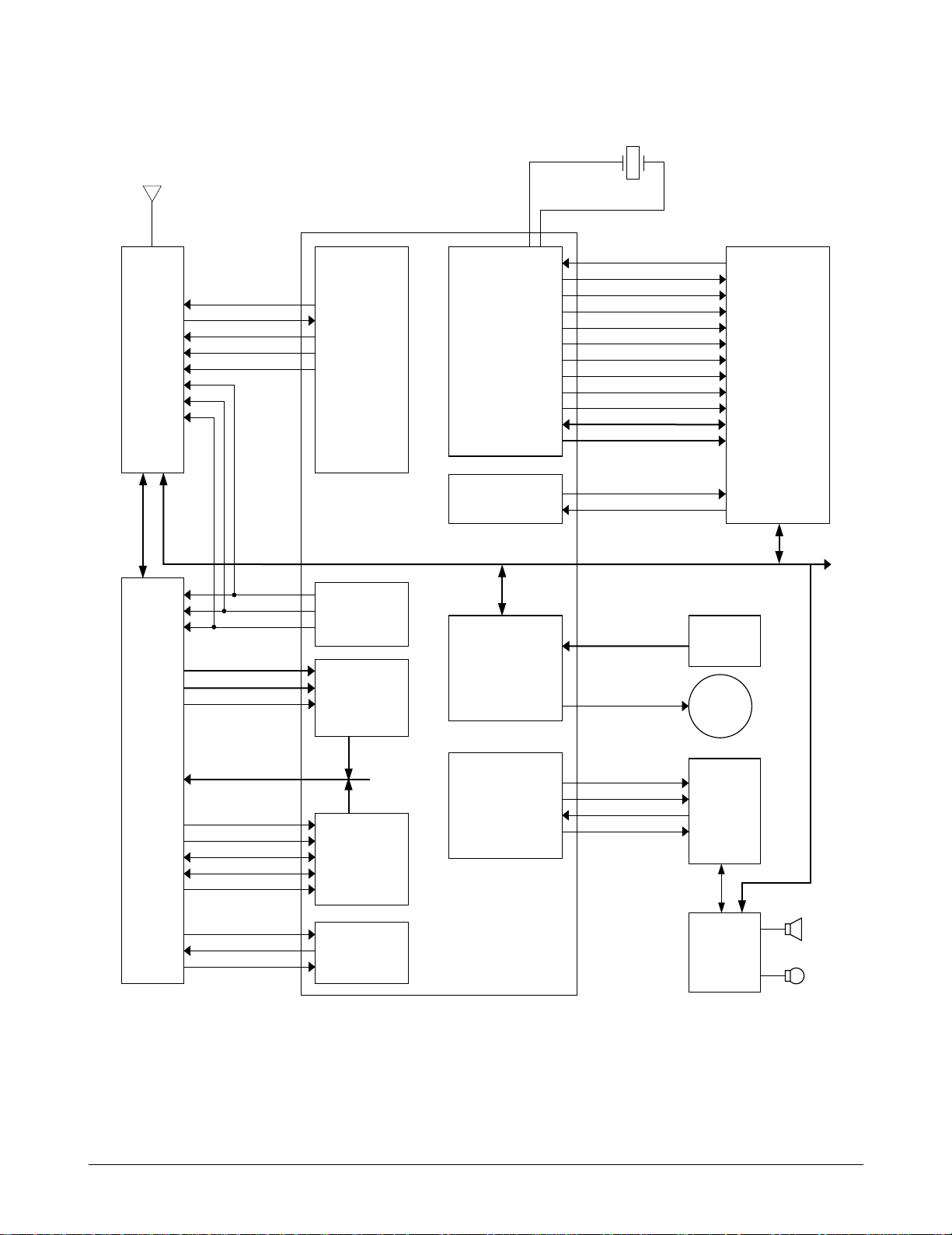
6-1-3 Baseband Part
MOBILE SYSTEM MODEM (MSM)
The MSM equipped with the INTEL 80186 CPU
core is an important component of the CDMA
cellular phone. The MSM comes in a 176 pins TQFP
package. The interface block diagram is shown on
page 6-3.
MICROPROCESSOR INTERFACE
The interface circuitry consists of reset circuit,
address bus (A0-A19), data bus (AD0-AD15), and
memory controls (ALE, DT_R, HWR/, LWR/,
RAM_CS/, ROM_CS).
INPUT CLOCK
¥CPU clock: 27 MHz
¥TXCO/4 (pin 34): 4.92 MHz. This clock signal from
the BBA is the reference clock for the MSM except
in CDMA mode.
¥CHIPX8 : 9.8304 MHz. The reference clock used
during the CDMA mode.
BBA INTERFACE
ADC Interface
ADC_CLK (pin 3), ADC_ENABLE (pin 1) and
ADC_DATA (pin 2) are required to control the
internal ADC in the BBA.
Data Port Interface
Includes the UART. Also, supports Diagnostic
Monitor (DM) and HP equipment interface.
CODEC Interface
The MSM outputs 2.048 MHz PCM_CLK (pin 19)
and 8 KHz CODEC_SYNC (pins 16,20) to the
CODEC (U310). The voice PCM data from the MSM
(U101) PCM_DIN (pin135) is compressed into 8KHz
by QCELP algorithm in the CDMA mode. In FM
mode, the data is processed by D_FM.
RF Interface
TX : TX_AGC_ADJ (pin 35) port is used to control
the TX power level and PA_ON (pin 44) signal is
used to control the power amplifier.
CDMA, FM Data Interface
¥TXIQDATA0-7 (pins 24-32) : TX data bus used
during both CDMA and FM mode.
¥C_RX_IDATA0-3 (pins 16-20) and C_RX_QDATA0-
3 (pins 12-15) : RX data bus used during CDMA
mode.
¥FM_RX_IDATA (pin 7) and FM_RX_QDATA (pin
8) : RX data bus used during FM mode.
Clock
¥TX_CLK (pin 22), TX_CLK/(pin 23) : Analog to
Digital Converter (ADC) reference clock used in
TX mode.
¥CHIPX8 : ADC reference clock used in CDMA RX
mode.
¥FMCLK : Reference clock in FM RX mode.
RX : AGC_REF (pin 36) port is used to control the
RX gain and TRK_LO_ADJ (pin 45) is used to
compensate the TCXO clock.
General Purpose I/O Register Pins
Input/output ports to control external devices.
Power Down Control
When the IDLE/ signal turns LOW, only the TX
sections will be disabled. If both the IDLE/ and
SLEEP/ changes to LOW, all the pins except for the
TXCO is disabled.
6-2 Samsung Electronics
ANTENNA
PA_ON
SYNTH_LOCK
TRK_LO_ADJ
TX_AGC_ADJ
RX_AGC_ADJ
RESIN/
XTAL
RESOUT
LWR/
HWR/
RD/
DT_R/
PCS6/
RAM_CS/
ROM_CS/
EEPROM_CS/
AD0~AD15
A0~A19
PCM_CLK
PCM_SYNC
PCM_DIN
PCM_DOUT
DP_TX_DATA
DP_RX_DATA
KEYSENSE0~4
RINGER
IDLE/
SLEEP/
FM/
C_RX_IDATA0~3
C_RX_QDATA0~3
CHIPX8
FM_RX_IDATA
FM_RX_QDATA
FM_RX_STB
ADC_ENABLE
ADC_DATA
ADC_CLK
FM_RX_CLK
TXCO/4
I_OFFSET, Q_OFFSET
TXCLK, TXCLK/
TX_IQDATA0~7
CDMA
MODE
FM
MODE
RF
UNIT
Q5312
CDMA
BASEBAND
ANALOG 2
(BBA2)
MODE
CONTROL
SUPPORT
GENERAL
PURPOSE
INTERFACE
CODEC
AMP
SPK
MIC
KEYPAD
VOCODER
CORE
MSM 1. 0 CORE
(CDMA
PROCESSING)
DFM
PROCESSING
GENERAL
PURPOSE
ADC
SUPPORT
RF
INTERFACE
MSM2
80186
MICROPROCESSOR
CORE
FIFOED SERIAL
DATA PORT
EXTERNAL
RAM, ROM,
EEPROM,
DISPLAY &
OTHER
PERIPHERALS
RINGER
Circuit Description
Figure 6-1 Baseband Block Diagram
6-3Samsung Electronics

Circuit Description
6-1-4 Audio Part
TX AUDIO PATH
The voice signal output from microphone is filtered
and amplified by the internal OP-AMP and is
converted to PCM data by the CODEC (U310). This
signal is then applied to the MSM (U100)'s internal
vocoder.
RX AUDIO PATH
The PCM data out from the MSM is converted to
audio signal by ADC of CODEC (U310), is then
amplified by the speaker amplifier (U330) to be sent
to the speaker unit.
FM TX PATH
RX AUDIO PATH
De-Emphasis Circuit
This circuit is 1st LPF featuring -6dB/oct to reduce
signal loss and noise in Rx path.
Expander
The expander features 1:2 level to reduce signal loss
and noise in Rx path. The zero crossing level of the
expander is ±2.9 kHz/dev, attack time is 3 mS, and
release time is 13.5 mS.
Volume Adjust
Volume can be adjusted up to 6 steps for the user to
obtain a proper loudness of received signal.
Pre-Emphasis Circuit
The circuit features +6dB/oct to reduce signal loss
and noise in Tx path.
Compressor
The compressor features 2:1 level to reduce signal
loss and noise in Tx path. The zero crossing level of
the compressor is ±2.9 kHz/dev, attack time is 3 mS,
and release time is 13.5 mS.
Limiter
The limiter performs to cut ±0.53 Vp-p or higher
audio signal level so that the FM frequency
deviation is not over ±12kHz/dev. The function is
used to avoid confusion over phone line. LPF is
used to reduce a specific high frequency of limited
signal.
6-1-5 TX WBD, ST, And SAT
These signals are generated from MSM. The
modulation level of TX WBD and ST is
±8kHz/dev, and SAT is ±2kHz/dev.
6-1-6 Buzzer Driving Circuitry
Buzzer generates alert tone. When the buzzer
receives the timer signal from the MSM, it generates
alert tone. The buzzer level is adjusted by the alert
signal's period generated from the MSM timer.
6-1-7 Key Tone Generator
Ringer signal (pin 49) out from MSM (U100) is
passed through 2 serial LPF consisting of R341,
C342, R340, and C341, amplified at the speaker amp
(U330), and comes out to speaker. In hands-free
mode, the key tone is applied to RX audio line
through the LPF and C338, R335.
6-4 Samsung Electronics
 Loading...