

Page 1
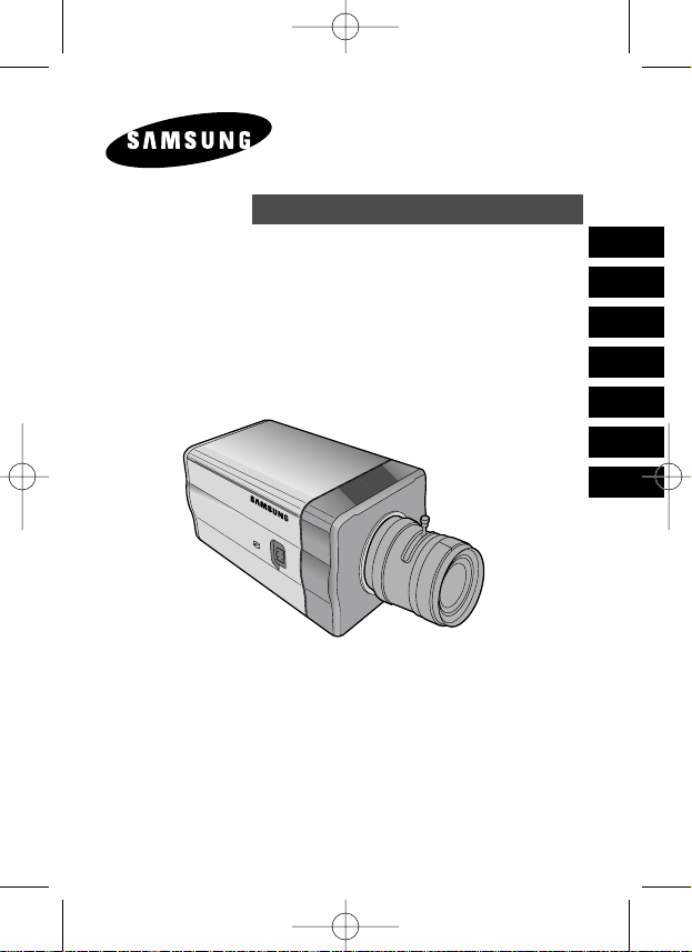
SCC-B2391(P)
SCC-B2091P
SCC-B2300
User’s Manual
DIGITAL COLOR CAMERA
E
D
F
Sp
I
Pl
R
(AB68-00511B)SCC-B2391-01Eng 2005.6.17 3:44 PM ˘`1
Page 2
E
Important Safety Instructions
CAUTION: TO REDUCE THE
RISK OF ELECTRIC SHOCK,
DO NOT REMOVE REAR
COVER. NO USER
SERVICEABLE PARTS INSIDE.
REFER TO QUALIFIED
SERVICE PERSONNEL.
To prevent damage which may result in fire or electric shock hazard,
do not expose this appliance to rain or moisture.
This device complies with part 15 of the FCC Rules. Operation is
subject to the following two conditions.
1) This device may not cause harmful interference, and
2) This device must accept any interference that may cause undesired
operation.
CAUTION:
Danger of explosion if battery is incorrectly replaced.
Replace only with the same or equivalent type recommended by the
manufacturer.
Dispose of used batteries according to the manufacturer’s instructions.
This symbol indicates
high voltage is present
inside. It is dangerous to
make any kind of contact
with any inside part of this
product.
This symbol alerts you
that important literature
concerning operation and
maintenance has been
included with this product.
CAUTION
RISK OF ELECTRIC
SHOCK DO NOT OPEN
2
(AB68-00511B)SCC-B2391-01Eng 2005.6.17 3:44 PM ˘ `2
Page 3
3
E
1. Read these instructions.
2. Keep these instructions.
3. Heed all warnings.
4. Follow all instructions.
5. Do not use this apparatus near water.
6. Clean only with dry cloth.
7. Do not block any ventilation openings. Install in accordance
with the manufacturer’s instructions.
8. Do not install near any heat sources such as radiators, heat
registers, or other apparatus (including amplifiers) that produce
heat.
9. Do not defeat the safety purpose of the polarized or groundingtype plug. A polarized plug has two blades with one wider than
the other. A grounding type plug has two blades and a third
grounding prong. The wide blade or the third prong are provided
for your safety. If the provided plug does not fit into your outlet,
consult an electrician for replacement of the obsolete outlet.
10. Protect the power cord from being from being walked on or
pinched particularly at plugs, convenience receptacles, and the
point where they exit from the apparatus.
11. Only use attachments/accessories specified by the manufacturer.
12. Use only with cart, stand, tripod, bracket, or table specified by
the manufacturer, or sold with the apparatus. When a used,
caution when moving the cart/apparatus combination to avoid
injury from tip-over.
13. Unplug this apparatus. When a cart is used, use caution when
moving the cart/apparatus combination to avoid injury from tipover.
14. Refer all servicing to qualified service personnel. Servicing is
required when the apparatus has been damaged in any way,
such as power-supply cord or plug is damaged, liquid has been
spilled or objects have fallen into the apparatus, the apparatus
has been exposed to rain or moisture, does not operate
normally, or been dropped.
(AB68-00511B)SCC-B2391-01Eng 2005.6.17 3:44 PM ˘ `3
Page 4

4
E
Chapter 1
Introduction ........................................................ 5
Chapter 2
Special Features ............................................. 6
Chapter 3
Installation ........................................................... 7
Checking the contents of the package .............. 7
Precautions in Installation and Use ................... 8
Connecting Auto Iris Lens Connector ................ 9
Lens Fixing
........................................................... 10
Setting Lens Selection Switch
.................... 11
Back Focus Adjustment
................................ 11
Connecting Cables and Checking Operation ....... 13
Chapter 4
Part Names and Functions ............................... 15
Product Specification ........................................ 20
Contents
(AB68-00511B)SCC-B2391-01Eng 2005.6.17 3:44 PM ˘ `4
Page 5
5
E
DAYNIGHT camera is a low brightness camera, which improves the sensitivity
by operating with a color mode at the over of regular brightness and operated
with a B/W mode by canceling the IR Cut function at the below of regular
brightness. Also, it can be used linked with the separated infrared ray emission
device. SCC-B2391(P)/B2091P has a high resolution with the 540 TV Lines of
horizontal resolution through the digital signal processing and OLPF.
❉
In the mechanical fluorescent light environment, if you attach MANUAL IRIS
LENS and turn the ELC switch among FUNCTION switches on, color may be
rolled.
In this case, supply AC power before you turn L/L switch among FUNCTION
switches on. (NTSC:60HZ , PAL:50HZ)
Chapter 1 Introduction
[DAYNIGHT]
It is a function of a color camera to delete the fiter with
the IR Cut function in an illumination below the standard
value so that it has a better sensitivity.
COLOR ROLLING is the problem that color on the
monitor screen changes non-periodically.
This happens when White Balance is not fixed,
because a mechanical fluorescent light flickers
when it’s cycle is the same to the cycle of the power
frequency.
(AB68-00511B)SCC-B2391-01Eng 2005.6.17 3:44 PM ˘ `5
Page 6
6
E
High Sensitivity
It has an up-to-date 1/3" Super-HAD IT CCD for an image of high sensitivity.
Resolution
It realizes high resolution resulting from full digital image processing
supported by a state-of-art digital signal technology.
Superior Back Light Adjustment Function
In case the object has a bright illumination or sunlight behind it, this camera
adjusts the image shaded by the back light for clear photographs.
Digital Power Supply Synchronization Method
The Full Digital Method Line Lock is realized in this camera, which adjusts
the vertical camera synchronization directly to improve controllability and
reliability of the camera.
Chapter 2 Special Features
(AB68-00511B)SCC-B2391-01Eng 2005.6.17 3:44 PM ˘ `6
Page 7
7
E
This chapter describes what should be checked before installation, how to
set the installation environment, and what should be done during installation.
Then, it describes how to install the camera and connect the cable in actual
circumstances.
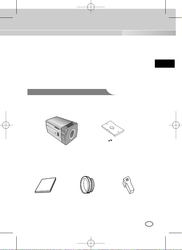
Camera
Holder(Mount)
C Mount Adapter
Chapter 3 Installation
Auto Iris
Lens Connector
User's Manual
Camera
Be sure to check if the following items are included in the package.
Checking the contents of the package
(AB68-00511B)SCC-B2391-01Eng 2005.6.17 3:44 PM ˘ `7
Page 8
8
E
① Do not attempt to disassemble the camera yourself.
➁ Be cautious in handling the camera. Avoid striking or shaking the
camera. Be cautious to avoid damage on the camera caused by improper
storage or operation.
➂ Do not expose this camera to rain or moisture. Do not operate this
camera on a wet place.
➃ Do not use strong or abrasive detergents when cleaning the camera
body. Use a dry cloth to clean the camera.
⑤ Keep the camera at a cool place away from the direct sunlight. Leaving it
under the direct sunlight may result in the malfunction of the unit.
Precautions in Installation and Use
(AB68-00511B)SCC-B2391-01Eng 2005.6.17 3:44 PM ˘ `8
Page 9
9
E
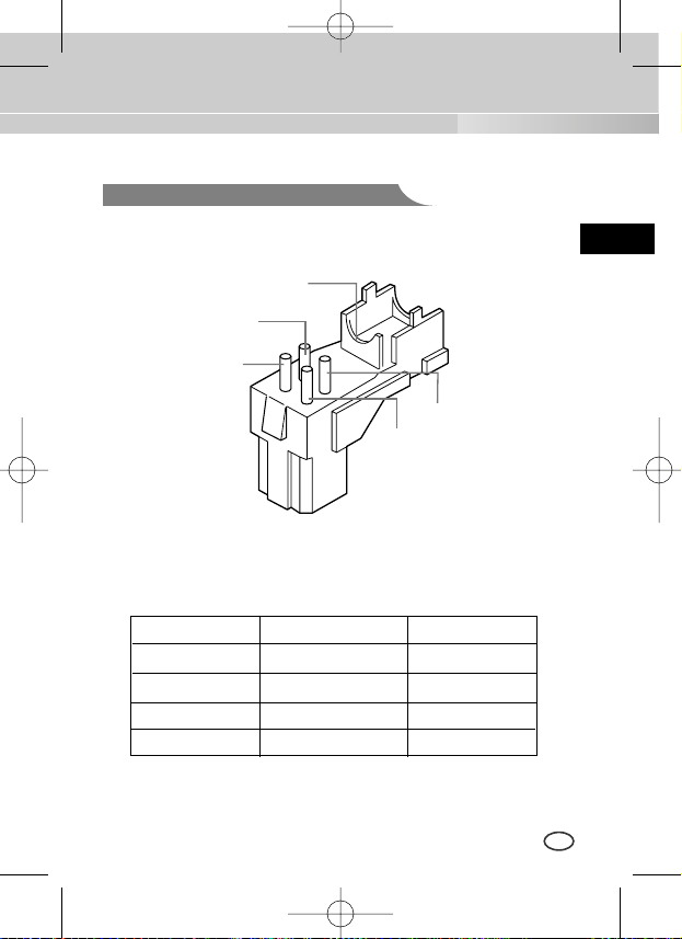
Connecting Auto Iris Lens Connector
Prepare the following Auto Iris Lens Connector supplied with the camera.
Connect the cable of the control cable, whose covering is stripped, to the
Auto Iris Lens Connector as shown below.
Rb
Pin3
Pin2
Pin4
Pin1
Pin No. DC Control Type VIDEO Control Type
1 Damp(-) Power (+12V)
2 Damp(+) N/A
3 Drive(+) VIDEO Signal
4 Drive(-) GROUND
(AB68-00511B)SCC-B2391-01Eng 2005.6.17 3:44 PM ˘ `9
Page 10
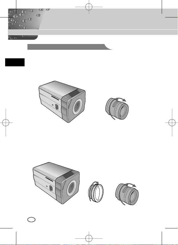
In case of CS lenses
Turn the CS lens clockwise until it is fixed as shown as follows.
In case of C lenses
Turn the C-mount adapter clockwise to fix it. Then turn the C lens
clockwise until it is fixed as follows.
Lens Fixing
CS lens
C lens
10
E
(AB68-00511B)SCC-B2391-01Eng 2005.6.17 3:44 PM ˘ `10
Page 11
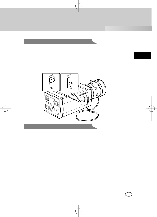
Setting Lens Selection Switch
11
E
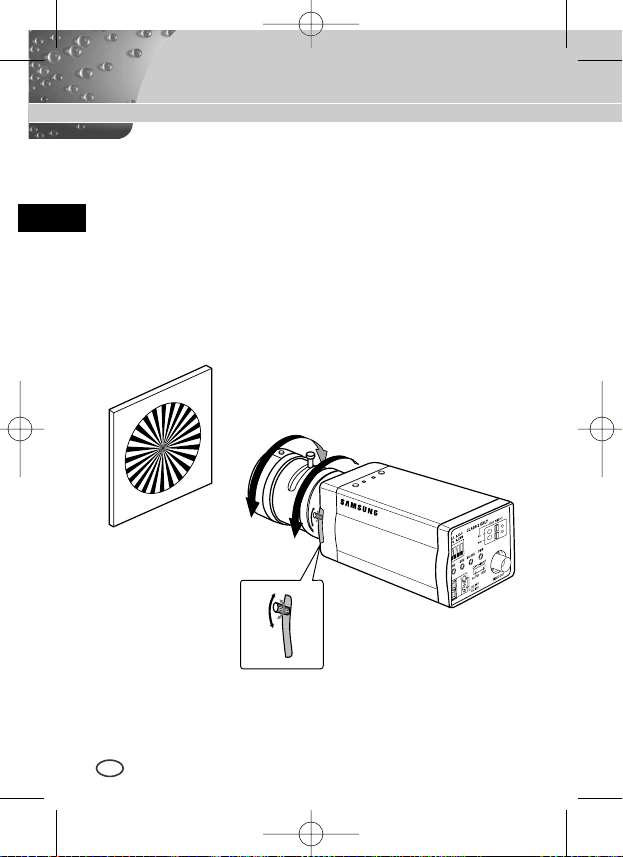
Back Focus Adjustment
The camera back focus is adjusted at the plant before delivery, but some
lenses are out of focus though the number differs in types. If it's the case,
you should make the back focus adjustment as follows. First, this is the back
focus adjustment procedure for fixed focus lenses.
Lenses without zoom function
① Image an object with high resolution(letticed) at more than 10m distance
and put the lens focus ring in the infinite(
∞
) position.
➁ Rotate the BACK FOCUS control bar until the object is seen best.
➂ Tighten the BACK FOCUS control bar fixing screw.
When lens mounting is completed, set the Lens selection Switch on the side
of the camera according to the mounted lens type. When the mounted lens
is an Auto Iris Lens of the DC control type, set the Lens Selection Switch to
"DC". When the mounted lens is an Auto Iris Lens of the Video control type,
set the Lens Selection Switch to "VIDEO".
(AB68-00511B)SCC-B2391-01Eng 2005.6.17 3:44 PM ˘ `11
Page 12
12
E
Lenses with zoom function
① Image an object with high resolution(letticed) at a distance of 3 to 5 m
and zoom in the lens as close to TELE as possible. Then adjust the lens
focus bar until the object is seen best.
➁ Zoom in the lens as close to WIDE as possible and adjust the BACK
FOCUS adjustment bar until the object is seen best.
➂ Repeat from ①to ➁ above 2 or 3 times until the focus on the ZOOM
TELE side is in line with that on the ZOOM WIDE side.
BACK FOCUS
CONTROL BAR
(AB68-00511B)SCC-B2391-01Eng 2005.6.17 3:44 PM ˘ `12
Page 13
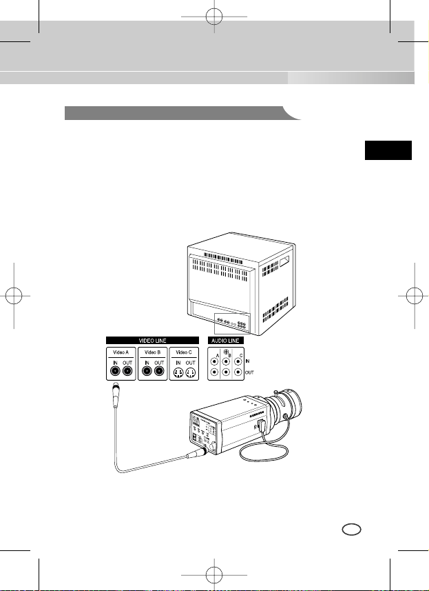
Connecting Cables and Checking Operation
13
E
1 First, connect the connector of the BNC cable to the Video Out terminal
2 Second, connect the other connector of the BNC cable to the Video In
terminal.
BNC cable
Video Out Terminal
Video In Terminal of
Monitor Rear Surface
(AB68-00511B)SCC-B2391-01Eng 2005.6.17 3:44 PM ˘ `13
Page 14
14
E
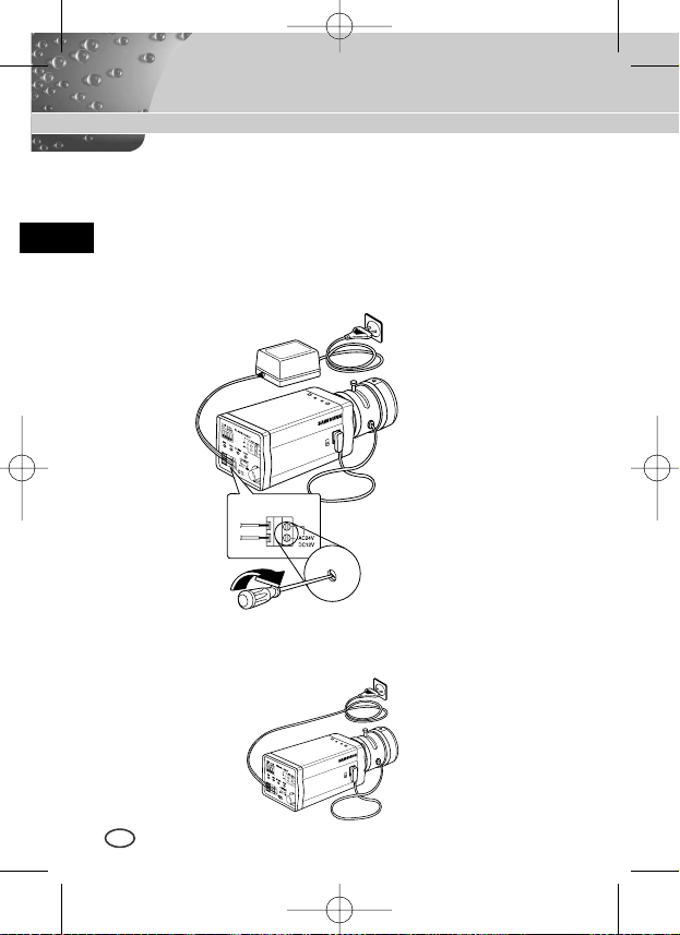
3 Third, connect the power cable.
① AC24V/DC12V Power Input Camera.
Connect 2 lines of the power adapter using a screwdriver to the power
IN Terminal of the camera as shown below.
❉
Without the distinction of the polarity, connect to the AC24V or DC12V
power source.
➁ AC230V Power Input Camera
Connect the power input cord to the AC230V power source.
(AB68-00511B)SCC-B2391-01Eng 2005.6.17 3:44 PM ˘ `14
Page 15
15
E
Chapter 4 Part Names and Functions
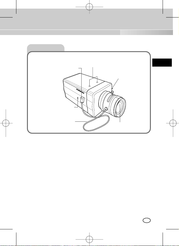
Side View
①
Mount Adapter Fixing Groove
This groove is used for screwing the mount adapter, a part of the bracket where the
camera will be installed.
➁
Camera Lens(Option)
This lens is installed in the camera.
❉
A camera lens with a stained surface should be cleaned softly with a lens
tissue or ethanol painted cotton cloth.
➂
Auto Iris Lens Connector
This connector provides the automatic shutter lens with power supply, control signal,
video signal, or DC signal necessary for the control of the lens shutter.
➃
Auto Iris Lens Control Cable
This cable transmits signal which controls the Iris.
⑤
ALC Lens Selection Switch
This Switch is used for select the type of Lens.
➅
Back Focus Control Bar
This bar is used for set back focus of the camera.
➃
Auto Iris Lens
Control Cable
⑤
ALC Lens
Selection Switch
➂
Auto Iris Lens
Connector
①
Mount Adapter Fixing
Groove
➅
Back Focus
Control Bar
➁
Camera Lens
(AB68-00511B)SCC-B2391-01Eng 2005.6.17 3:44 PM ˘ `15
Page 16

Rear View
16
E
AC24V/DC12V Camera (SCC-B2391(P)/B2300)
AC230V Camera (SCC-B2091P)
⑤
⑤
⑦
⑧
⑨
➁
➅
⑦
⑧
①
①
⑨
➂ ➃
➂ ➃
➁
➅
(AB68-00511B)SCC-B2391-01Eng 2005.6.17 3:44 PM ˘ `16
Page 17

17
E
① Power connection port
AC24V/DC12V Camera : It is a port connected to the power adaptor cable.
AC230V Camera : It is Power cord.
➁ POWER LED
If the power of a camera is supplied normally, the LED is ON.
➂➃INC and DEC Switch
Both switches increase or decrease the profit of RED and BLUE to fix a color
temperature as you wish while AWB among the FUNCTION switches is
off(USER) and control the vertical synchronous phase while both AWB and
L/L are on.
⑤ FUNCTION Switch
1. L/L 2. ELC
3. FL 4. AWB
SW1 SW2 SW3 SW4
ON
(AB68-00511B)SCC-B2391-01Eng 2005.6.17 3:44 PM ˘ `17
Page 18

18
E
1) SW1(L/L) :
Set to OFF, the camera activates the internal synchronization mode and set to ON, the power
synchronization mode. If you connect multi cameras to the sequential switcher to enter the
automatic conversion mode, the screen will bounce every screen while the camera stays in
INT(internal synchronization). Such bouncing phenomena may be cleared and screen conversion
becomes smooth by setting the L/L switch to ON and using the INT/DEC switch to control the
vertical synchronous phase.
❉
If you want to control the vertical synchronous phase with the INT/DEC switch when L/L is set
to ON, you shall set SW4 to AWB ON.
❉
In case of DC12V, INT(internal synchronizer) will be fixed without regard to ON/OFF of L/L.
2) SW2(ELC) :
Use this switch with the Manual Iris Lens. While this switch is ON, the speed of the electronic
shutter varies with the brightness of the subject from 1/60(50) to 1/100,000 sec for automatically
controlling the brightness of the screen. However, with the Auto Iris Lens (DC or Video Control),
be sure to switch OFF.
Color Rolling may occur in this mode. In that case, input AC power source to the camera and
select SW1 "ON".
(NTSC : 60HZ, PAL : 50HZ)
3) SW3(FL):
This is to prevent flicker on the screen when NTSC system is used in 50HZ power supply region
and PAL system is used in 60HZ power supply region. That is to prevent shaking on the
screen resulted from the discordance of the vertical sync frequency and the flicker frequency of
the illumination. While this switch is ON, the electronic shutter is fixed to 1/100sec (NTSC) or
1/120 sec (PAL).
4) SW4(AWB):
When setting up ON, the color of screen is adjusted automatically in accordance with the change
of lighting color temperature by the change of outer environment. (ATW) If the lighting condition is
steady, OFF setting is available. The camera memorizes the lighting color temperature at the
time when the switch setting is changed from ON to OFF, and the camera color is adjusted to the
memorized color temperature. (AWC) If the lighting color temperature is changed and you want
to make the camera be memorized/operated with the changed color temperature, re-operate the
switch On/Off operation. However, be aware that an error may occur under the following
conditions.
First, a case that the subject is big, single color of the high chroma, and in the center of
the screen or a case with almost no white color on the screen.
Second, a case with a specific illumination such as a natrium lamp
(AB68-00511B)SCC-B2391-01Eng 2005.6.17 3:44 PM ˘ `18
Page 19

19
E
➅
DC IRIS Level Controller
When the ALC lens selection switch is set to DC, use the same control bar as the
driver to control the IRIS level.
⑦
Video Output Port
This port shall be connected to the monitor video input port or equivalent. You
may output camera video signals through this port.
⑧
DAYNIGHT Selection Switch
If you set this switch to AUTO, the DAYNIGHT function will be automatically
activated according to the illumination. Under poor illumination, IR Filter will be
automatically eliminated in the black and white mode(BW Mode) to raise the
sensitivity but under good illumination, IR Filter will be automatically inserted in
the color mode(COLOR Mode).
IR Filter responds to the preset Duration Time (Delivery Condition:10 seconds).
When you convert DAYNIGHT in the AUTO mode, you shall set Duration Time
as follows. (Please turn off the L/L switch and the AWB switch to begin with).
Whenever you convert the DAYNIGHT selection switch from EXT to AUTO while
you hold on to the INC/DEC switch, DURATION TIME becomes 10s, 30s, 60s,
90s, 120s, and 150s in sequence. Upon setup, you shall cancel pressing the
INC/DEC switch to save the setup condition in the camera. Upon saving, the
DAYNIGHT mode will be automatically converted depending on DURATION
TIME even in the event of POWER On/Off.
For resetting, please repeat the above procedure. (Upon resetting, you may r
eturn both L/L and AWB to the previous condition.)
If you set this switch to EXT, COLOR/BW Mode varies depending on the external
signal input to the DAYNIGHT external signal input port(
⑨
).
⑨
DAYNIGHT External Signal Input Port
When the DAYNIGHT selection switch(⑧) is set to EXT, COLOR/BW Mode
varies depending on the input signal to this port.
The input terminal shall be DC5V pull-up input and over 0.2mA.
OFF : Open contact
ON : Closed contact
(AB68-00511B)SCC-B2391-01Eng 2005.6.17 3:44 PM ˘ `19
Page 20

20
E
Product Specification
ITEM
Contents
Product Type CCTV Camera
Broadcasting System PAL STANDARD SYSTEM
CCD 1/3 Super-HAD CCD
Effective Pixels 752(H) x 582(V)
Scanning Type 625 Line, 2:1 Interlace
INTERNAL : 15,625Hz(H)
50 Hz(V)
LINE LOCK :
15,625Hz(H)
50 Hz(V)
INTERNAL
LINE LOCK(When AC Power source is used)
Resolution(H) 540(Color)/570(B/W) TV Lines
S/N Ratio About 50dB
DAYNIGHT
AUTO / EXT
Frequency
Sync Type
Minimum Illumination
of Object
0.3 Lux(Color) / 0.06 Lux(B/W)
(AB68-00511B)SCC-B2391-01Eng 2005.6.17 3:44 PM ˘ `20
SCC-B2391P/B2091P
Page 21

ITEM
Contents
ALC
DC IRIS LENS
ALC/ELC
VIDEO LENS
ELC
Electronic Shutter Iris Function (Max. 1/100 Ksec)
Color Temperature
AWB/MANUAL
BLC
ON
AGC
ON
Video Output
COMPOSITE VIDEO OUT
1V p_p 75Ω/BNC
Operating Temp
-10°C~+50
°C
Operating Humidity
~90%
Size 68(W)x55(H)x128.5(D)mm(included BNC)
21
E
Power Source
B2391P : AC24V±10%(50Hz±0.3Hz), DC12V+10%~-5%
B2091P : AC220V~AC240V(50Hz
±
0.3Hz)
Power Consumption
B2391P : About 3W
B2091P : About 4W
Weight
B2391P :
450g
B2091P : 550g
(AB68-00511B)SCC-B2391-01Eng 2005.6.17 3:44 PM ˘ `21
Page 22

ITEM
Contents
Product Type CCTV Camera
Broadcasting System NTSC STANDARD SYSTEM
CCD 1/3 Super-HAD CCD
Effective Pixels
B2391 :
768(H) x 494(V)
B2300 :
510(H) x 492(V)
Scanning Type 525 Line, 2:1 Interlace
INTERNAL : 15,734Hz(H)
59.94 Hz(V)
LINE LOCK : 15,750Hz(H)
60 Hz(V)
INTERNAL
LINE LOCK(When AC Power source is used)
Resolution(H) B2391 : 540(Color)/570(B/W) TV Lines
B2300 : 400(Color)/420(B/W) TV Lines
S/N Ratio About 50dB(AGC OFF)
DAYNIGHT
AUTO / EXT
22
E
SCC-B2391/B2300
Frequency
Sync Type
Minimum Illumination
of Object
B2391 : 0.3 (Color) / 0.06 (B/W)Lux
B2300 : 0.2 (Color) / 0.03 (B/W)Lux
Product Specification
(AB68-00511B)SCC-B2391-01Eng 2005.6.17 3:44 PM ˘ `22
Page 23

23
E
ITEM
Contents
ALC
DC IRIS LENS
ALC/ELC
VIDEO LENS
ELC
Electronic Shutter Iris Function (Max. 1/100 Ksec)
Color Temperature
AWB/MANUAL
BLC
ON
AGC
ON
Video Output
COMPOSITE VIDEO OUT
1V p_p 75Ω/BNC
AC24V ±10%(60Hz±0.3Hz), DC12V+10%~-5%
Power Consumption About 3Watts
Operating Temp
-10°C~+50
°C
Operating Humidity
~90%
Size 68(W)x55(H)x128.5(D)mm(included BNC)
Weight
450g
Power Source
(AB68-00511B)SCC-B2391-01Eng 2005.6.17 3:44 PM ˘ `23
Page 24

Part No.:AB68-00511B
Correct Disposal of This Product
(Waste Electrical & Electronic Equipment)
(Applicable in the European Union and other European countries with separate collection systems)
This marking shown on the product or its literature, indicates that it should not be disposed with other
household wastes at the end of its working life. To prevent possible harm to the environment or human
health from uncontrolled waste disposal, please separate this from other types of wastes and recycle it
responsibly to promote the sustainable reuse of material resources.
Household users should contact either the retailer where they purchased this product, or their local
government office, for details of where and how they can take this item for environmentally safe recycling.
Business users should contact their supplier and check the terms and conditions of the purchase contract.
This product should not be mixed with other commercial wastes for disposal.
(AB68-00511B)SCC-B2391-01Eng 2005.6.17 3:44 PM ˘ `24
Page 25

Pl
Instrukcja obs∏ugi
KOLOROWA KAMERA
SCC-B2391(P)
SCC-B2091P
SCC-B2300
(AB68-00511B)SCC-B2391-06Pl 2005.6.17 3:31 PM ˘ ` 111
Page 26

2
Pl
OSTRO˚NIE: ABY ZMNIEJSZYå
RYZYKO PORA˚ENIA PRÑDEM NIE
NALE˚Y ZDEJMOWAå TYLNEJ CZ¢ÂCI
OBUDOWY. BRAK TAM CZ¢ÂCI DO
SAMODZIELNEJ NAPRAWY PRZEZ
U˚YTKOWNIKA. ZG¸OÂ USZKODZENIE
DO WYKWALIFIKOWANEGO PUNKTU
SERWISU.
W celu unikni´cia uszkodzeƒ, które mogà doprowadziç do po˝aru
lub pora˝enia pràdem, nie wystawiaç urzàdzenia na deszcz i nie
umieszczaç w miejscach wilgotnych.
Urzàdzenie podlega zasadom FCC (Federalnej Komisji
Komunikacyjnej). Funkcjonowanie podporzàdkowane jest
nast´pujàcym warunkom:
1) urzàdzenie nie mo˝e powodowaç zak∏óceƒ
2) Urzàdzenie musi zaakceptowaç zak∏ócenia, które mog´
prowadziç do niew∏aÊciewego funkcjonowania.
OSTRZE˚ENIE:
Wymiana baterii na niew∏aÊciwe grozi wybuchem.
Wymieniaj baterie na identyczne lub na baterie zamienne zalecane
przez producenta.
Zu˝yte baterie nale˝y wyrzuciç zgodnie z zaleceniami producenta.
Symbol ten ostrzega
przed wysokim
napi´ciem wewnàtrz.
Niebezpieczny jest
kontakt z jakimikolwiek
elementami wewnàtrz
urzàdzenia.
Symbol ten informuje, i˝
do produktu do∏àczono
opis funkcjonowania oraz
utrzymania urzàdzenia.
OSTRO˚NIE!
NIE OTWIERAå - GROZI
PORA˚ENIEM PRÑDEM
Important Safety Instructions
(AB68-00511B)SCC-B2391-06Pl 2005.6.17 3:31 PM ˘ ` 112
Page 27

3
Pl
1. Zapoznaj si´ z instrukcjami.
2. Zachowaj instrukcje obs∏ugi.
3. Zwracaj uwag´ na wszystkie ostrze˝enia.
4. Post´puj zgodnie z instrukcjami.
5. Nie u˝ywaj tego urzàdzenia w pobli˝u wody.
6. CzyÊç jedynie suchà szmatkà.
7. Nie blokuj wejÊç wentylacyjnych. Dokonaj instalacji zgodnie ze
wskazówkami proucenta.
8. Nie instaluj w pobli˝u êróde∏ ogrzewania, takich jak: grzejniki,
kaloryfery, i inne urzàdzenia ( równie˝ wzmacniacze), które
powodujà podwy˝szonà temperatur´.
9. Nie ograniczaj bezpieczeƒstwa wtyczki polaryzowanej lub
uziemienia. Wtyczka polaryzowana posiada dwie blaszki, jednà
szerszà od drugiej. Wtyczka uziemienia posiada dwa metalowe
bolce i trzeci uziemiajàcy. Szerokie blaszki lub bolec
uziemiajàcy majà zapewniç bezpieczeƒstwo. JeÊli wtyczka w
zestawie nie pasuje do gniazda, które znajduje si´ w miejscu
instalacji, skonsultuj si´ z elektrykiem w celu wymiany gniazda.
10. Zabezpiecz przewód zasilania przed deptaniem lub
ÊciÊni´ciem, szczególnie w miejscu gdzie ∏àczy si´ z wtyczkà,
przy prze∏àcznikach i przy wyjÊciu urzàdzenia.
11. U˝ywaj jedynie zalecanych przez producenta dodatkowych
urzàdzeƒ / akcesoriów.
12. Ustawiaj jedynie na wózkach, stojakach, statywach podpórkach
lub stolikach wskazanych przez producenta lub sprzedawanych
wraz z urzàdzeniem. Aby uniknàç przewrócenia i uszkodzenia
podczas przesuwania z∏àczonego zestawu nale˝y zachowaç
ostro˝noÊç.
13. Roz∏àcz urzàdzenie. JeÊli u˝ywasz wózka, ostro˝nie przesuwaj
wózek/ zainstalowane na nim urzàdzenie aby uniknàç
uszkodzeƒ w wyniku przewrócenia si´ sprz´tu.
14. Wszelkie naprawy powierz wykwalifikowanej obs∏udze
technicznej. Urzàdzenie nale˝y naprawiç w przypadku ka˝dego
uszkodzenia, np. uszkodzenie przewodu sieciowego, wtyczki,
rozlania p∏ynu na urzadzenie, lub w celu usuni´cia przedmiotu,
który znalaz∏ si´ wewnàtrz urzàdzenia, w przypadku gdy
urzàdzenie zosta∏o wystawione na deszczu lub w wilgoci, kiedy nie
funkcjonuje w∏aÊciwie lub zosta∏o upuszczone.
(AB68-00511B)SCC-B2391-06Pl 2005.6.17 3:31 PM ˘ ` 113
Page 28

4
Pl
Rozdzia∏ 1
Wprowadzenie.......................................................5
Rozdzia∏ 2
Charakterystyka.....................................................6
Rozdzia∏ 3
Instalacja ................................................................7
Sprawdzanie zawartoÊci opakowania ..................7
Ârodki ostro˝noÊci podczas instalacji i
u˝ytkowania ...........................................................8
Pod∏àczanie z∏àcza obiektywu z automatycznà ....
przes∏onà................................................................9
Mocowanie obiektywu.........................................10
Ustawienia w∏àcznika wyboru obiektywu...........11
Regulacja ostroÊci t∏a ..........................................11
Pod∏àczanie przewodów I sprawdzania ................
funkcjonowania....................................................13
Rozdzia∏ 4
Nazwy i funkcje cz´Êci.........................................15
Dane techniczne..................................................20
Spis treÊci
(AB68-00511B)SCC-B2391-06Pl 2005.6.17 3:31 PM ˘ ` 114
Page 29

Kamera DAYNIGHT(Dzieƒ/noc) jest kamerà o niskiej jasnoÊci, co powoduje
zwi´kszenie czu∏oÊci przy funkcjonowaniu w trybie kolorów w jasnoÊci powy˝ej
przeci´tnej jasnoÊci zaÊ w trybie B/W po anulowaniu funkcji IR Cut poni˝ej
regularnej jasnoÊci. Mo˝e byç równie˝ stosowana w po∏àczeniu z oddzielnym
urzàdzeniem emitujàcym promieniowanie podczerwieni. Kamera ta ma wysokà
rozdzielczoÊç 540 Linii TV rozdzielczoÊci poziomej poprzez przetwarzanie
sygna∏u cyfrowego oraz OLPF.
❉
W otoczeniu Êwiat∏a jarzeniowego za∏àczenie Obiektyw z MANUALNÑ
PRZES¸ONÑ (automatycznej przes∏ony) i w∏àczenie przycisku ELC wÊród
prze∏àczników funkcyjnych (FUNCTION) mo˝e powodowaç falowanie barw. W
takim przypadku nale˝y przed w∏àczeniem przycisku funkcyjnego L/L pod∏àczyç
zasilania pràdem zmiennym AC. (NTSC:60HZ , PAL:50HZ)
5
Pl
Rozdzia∏ 1 Wprowadzenie
[DAYNIGHT]
Jest to funkcja kamery kolorowej s∏u˝àca usuwaniu filtra
z funjkcjà IR Cut w oÊwietleniu poni˝ej standardowej
wartoÊci, co poprawia czu∏oÊç.
Falowanie barw polega na nieregularnych zmianach
barw na ekranie. Problem ten pojawia si´, gdy balans
bieli nie jest ustawiony ze wzgl´du na migotanie Êwiat∏a
jarzeniowego wywo∏ane zmianami napi´cia zasilania.
(AB68-00511B)SCC-B2391-06Pl 2005.6.17 3:31 PM ˘ ` 115
Page 30

6
Pl
Wysoka czu∏oÊç
Dla obrazu o wysokiej czu∏oÊci posiada nowoczesny 1/3" Super-HAD IT
CCD .
RozdzielczoÊç
Wysoka rozdzielczoÊç zapewniona jest dzi´ki pe∏nemu cyfrowemu
przetwarzaniu obrazu w po∏àczeniu z doskona∏à technologià sygna∏u
cyfrowego.
Funkcja regulacji oÊwietlenia w tle
W przypadku, gdy w tle za obiektem znajduje si´ ostre oÊwietlenie lub
promienie s∏oneczne, kamera reguluje jasnoÊç obiektu przyciemnionego
przez to oÊwietlenie w celu uzyskania w∏aÊciwego oÊwietlenia fotografii.
Metoda synchronizacji zasilania cyfrowego
Kamera ta wyposa˝na jest w Full Digital Method Line Lock. Funkcja ta
dostosowuje symchronizacj´ pionowà bezpoÊrednio, w celu poprawienia
jakoÊci obs∏ugi i niezawodnoÊci kamery.
Rozdzia∏ 2 Charakterystyka
(AB68-00511B)SCC-B2391-06Pl 2005.6.17 3:31 PM ˘ ` 116
Page 31

7
Pl
Rozdzia∏ ten opisuje co nale˝y sprawdziç przed zainstalowaniem, w jaki
sposób przygotowaç otoczenie instalowanego urzàdzenia i w jaki sposób
nale˝y je zainstalowaç. Nast´pnie opisany zosta∏ sposób instalacji kamery
oraz po∏àczenia przewodów w danych warunkach.
Rozdzia∏ 3 Instalacja
Sprawdê, czy nast´pujàce elementy znajdujà si´ w opakowaniu.
Sprawdzanie zawartoÊci opakowania
Uchwyt
(Mocowanie)
Zasilacz
mocowania C
Automatyczna przes∏ona
¸àcze obiektywu
Instrukcja obs∏ugi
Kamera
(AB68-00511B)SCC-B2391-06Pl 2005.6.17 3:31 PM ˘ ` 117
Page 32

8
Pl
① Nie rozmontowuj kamery samodzielnie
➁ Ostro˝nie obchodê si´ z kamerà. Unikaj wstrzàsów lub uderzeƒ.
Przechowuj i pos∏uguj si´ kamerà we w∏aÊciwy sposób, by uniknàç jej
uszkodzenia.
➂ Nie wystawiaj kamery na dzia∏anie deszczu lub wilgoci. Nie u˝ywaj
kamery w mokrych miejscach.
➃ Podczas czyszczenia unikaj silnie dzia∏ajàcych Êrodków. Kamer´ nale˝y
przecieraç suchà szmatkà.
⑤ UmieÊç kamer´ w ch∏odnym miejscu z dala od bezpoÊredniego
promieniowania s∏onecznego. BezpoÊredni wp∏yw promieni s∏onecznych
mo˝e powodowaç niew∏aÊciwe funkcjonowanie kamery.
Ârodki ostro˝noÊci podczas instalacji i u˝ytkowania
(AB68-00511B)SCC-B2391-06Pl 2005.6.17 3:31 PM ˘ ` 118
Page 33

9
Pl
Pod∏àczanie z∏àcza obiektywu z automatycznà przes∏onà
Przygotuj do∏àczone do kamery z∏àcze obiektywu z automatycznà przes∏onà.
Pod∏àcz przewód obs∏ugi z os∏onà w paski do z∏àcza obiektywu z
automatycznà przes∏onà.
Nr Koƒcówki Typ kontroli pràdu sta∏ego Typ kontroli VIDEO
1 Damp(-) Power (+12V)
2 Damp(+) N/A
3 Drive(+) Sygna∏ VIDEO
4 Drive(-) UZIEMIENIE
Rb
Pin3
Pin2
Pin4
Pin1
(AB68-00511B)SCC-B2391-06Pl 2005.6.17 3:31 PM ˘ ` 119
Page 34

Dla obiektywów CS
Przekr´caj obiektyw CS zgodnie z kierunkiem ruchu wskazówek zegara
dopóki nie zostanie zamocowany jak na obrazku.
Dla obiektywów C
Przekr´caj z∏àcze do monta˝u C zgodnie z ruchem wskazówek zegara,
by go zamocowaç. Nast´pnie przekr´ç obiektyw C zgodnie z ruchem
wskazówek zegara w celu jego zamocowania.
Mocowanie obiektywu
Obiektyw CS
Obiektyw C
10
Pl
(AB68-00511B)SCC-B2391-06Pl 2005.6.17 3:31 PM ˘ ` 120
Page 35

Regulacja ostroÊci t∏a
Ustawienia w∏àcznika wyboru obiektywu
11
Pl
OstroÊç t∏a regulowana jest przed dostarczeniem, jednak niektóre
obiektywy sà nieostre mimo ˝e liczba ró˝ni si´ w zale˝noÊci od typu. W
takim przypadku nale˝y dokonaç nast´pujàcej regulacji.
Jest to proces regulacji ostroÊci t∏a dla zamocowanych obiektywów.
Obiektywy bez funkcji zoom
① Obejmij obiekt o du˝ej rozdzielczoÊci w dystansie powy˝ej 10m i ustaw
obr´cz przes∏ony w pozycji nieskoƒczonoÊci
(∞).
➁ Przekr´ç BACK FOCUS do chwili najlepszej widocznoÊci obiektu.
➂ Umocnij pozycj´ ustawienia BACK FOCUS przykr´cajàc Êrubk´.
Po zamontowaniu obiektywu ustaw przycisk wyboru obiektywu z boku
kamery zgodnie z rodzajem zamontowanego obiektywu.
W przypadku zamontowania obiektywu z automatycznà przes∏onà
dzia∏ajàcego pod zasilaniem DC, ustaw prze∏àcznik wyboru obiektywu w
pozycji “DC”.
Je˝eli zamontowany obiektyw to obiektyw z automatycznà przes∏onà typu
video, ustaw prze∏àcznik wyboru obiektywu na “VIDEO”.
(AB68-00511B)SCC-B2391-06Pl 2005.6.17 3:31 PM ˘ ` 121
Page 36

12
Pl
Obiektywy z funkcjà zoom
① Obejmij obiekt o du˝ej rozdzielczoÊci w dystwnsie 3-5 m i przybli˝
zoom obiektywu najbli˝ej TELE jak to mo˝liwe. Nast´pnie reguluj
ostroÊç obiektywu by ustawiç go w najlepszej widocznoÊçi.
➁ Przybli˝ zoom w oobiektywie najbli˝ej jak to mo˝liwe do WIDE i
reguluj BACK FOCUS a˝ do uzyskania najlepszej widocznoÊci
obiektu.
➂ 2 lub 3-krotnie powtórz kroki ① i ➁ do momentu, gdy obiektyw w
ZOOM TELE b´dzie w równiej linii z linià z boku ZOOM WIDE.
Ognisko z ty∏u Kontrolka
(AB68-00511B)SCC-B2391-06Pl 2005.6.17 3:31 PM ˘ ` 122
Page 37

Pod∏àczanie przewodów I sprawdzania funkcjonowania
13
Pl
1 Po∏àcz z∏àcze przewodu BNC do terminaly Video In.
2 Pod∏àcz inne z∏àcza kabla BNC do terminalu Video In.
Przewód BNC
Terminal WyjÊcia
Video
terminal Video In z ty∏u
urzàdzenia
(AB68-00511B)SCC-B2391-06Pl 2005.6.17 3:31 PM ˘ ` 123
Page 38

14
Pl
3 Pod∏àcz przewód zasilania
① Kamera o zasilaniu AC24V/DC12V
Pod∏àcz dwie linie zasilacza za pomocà Êrubokr´tu z terminalem IN
kamery, jak na rysunku poni˝ej.
❉
Bez polaryzacji po∏àcz do êród∏a zasilania AC24V lub DC12V
➁ Kamera o zasilaniu AC230V
Po∏àcz przewód zasilania do êród∏a zasilania AC230V.
(AB68-00511B)SCC-B2391-06Pl 2005.6.17 3:31 PM ˘ ` 124
Page 39

15
Pl
Rozdzia∏ 4 Nazwy i funkcje cz´Êci
Widok z boku
①
Mocowanie zasilania Wy˝∏obienie
Wy˝∏obienie to wykorzystywane jest w celu przykr´cenia z∏àcznika, tego elementu
gdzie kamera b´dzie zainstalowana.
➁
Obiektyw kamery (opcja)
Obiektyw ten instalowany jest w kamerze.
❉
Obiektyw kamery w przypadku poplamienia powierzchni nale˝y czyÊciç
chusteczkà do obiektywów lub bawe∏nianà szmatkà zmoczonà w etanolu.
➂
¸àcznik obiektywu Auto Iris
¸àcznik ten doprowadza zasilanie, sygna∏ kontrolny lub sygna∏ DC do automatycznej
przes∏ony.
➃
Przewód zasilanie obiektywu z automatycznà przes∏onà
Przewód ten doprowadza sygna∏ kontrolujàcy przes∏on´.
⑤
ALC prze∏àcznik wyboru obiektywu
S∏u˝y wybieraniu rodzaju obiektywu.
➅
Ognisko z ty∏u Kontrolka
Przycisk ten s∏u˝y do ustawiania ogniska t∏a kamery.
➃
Przewód zasilanie
obiektywu z automatycznà
przes∏onà
⑤
ALC prze∏àcznik
wyboru obiektywu
➂
¸àcznik obiektywu Auto Iris
①
Mocowanie zasilania
Wy˝∏obienie
➅
Ognisko z ty∏u
Kontrolka
➁
Obiektyw kamery
(AB68-00511B)SCC-B2391-06Pl 2005.6.17 3:31 PM ˘ ` 125
Page 40

16
Pl
Widok z ty∏u
AC24V/DC12V Kamera (SCC-B2391(P)/B2300)
AC230V Kamera (SCC-B2091P)
⑦
⑧
⑨
➁
➅
⑦
⑧
①
➁
➅
⑤
⑤
①
⑨
➂ ➃
➂ ➃
(AB68-00511B)SCC-B2391-06Pl 2005.6.17 3:31 PM ˘ ` 126
Page 41

17
Pl
① Port zasilania
Kamera AC24V/DC12V: Jest to port po∏àczony do przewodu zasilania.
Kamera AC230V: Przewód zasilania.
➁ Dioda zasilania
JeÊli zasilanie kamery odbywa si´ bez zak∏óceƒ dioda jest w pozycji
ON(w∏àczonej).
➂➃Prze∏àcznik INC oraz DEC
Obydwa prze∏àczniki zwi´kszajà lub zmniejszajà korzystne ustawienia barwy
czerwonej i niebieskiej w celu ustawienia oczekiwanej temperatury barwy,
zaÊ AWB jeden z prze∏àczników funkcyjnych (FUNCTION) jest wy∏àczony
(OFF) (U˚YTKOWNIK) i kontroluje pionowà synchronicznà faz´ podczas
gdy AWB oraz L/L sà w∏àczone.
⑤ Prze∏àcznik funkcji
1. L/L 2. ELC
3. FL 4. AWB
SW1 SW2 SW3 SW4
ON
(AB68-00511B)SCC-B2391-06Pl 2005.6.17 3:31 PM ˘ ` 127
Page 42

18
Pl
1) SW1(L/L) :
W pozycji OFF kamera aktywuje tryb synchronizacji wewn´trznej, w pozycji ON tryb
synchronizacji mocy. Pod∏àczanie kilku kamer do prze∏àcznika sekwencyjnego w celu
wejÊcia w tryb automatycznej konwersji, ekran poka˝e ka˝dy z obrazów, gdy kamera
pozostanie w trybie INT (synchronizacja wewn´trzna). Zjawisko to mo˝na wyczyÊciç i
konwersja kamery staje si´ p∏ynna poprzez ustawienie L/L w pozycj´ ON i u˝ywanie
prze∏àcznika INT/DEC w celu kontroli poziomej fazy synchronicznej.
❉
W celu obs∏ugi pionowej fazy synchronicznie z INT/DEC podczas gdy L/L jest ustawiony w
pozycje ON, nale˝y ustawiç SW4 w pozycj´ AWB ON.
❉
Dla DC 12 V, INT (internal synchronizer, synchronizator wewn´trzny) zostanie ustawiony
bez zwiàzku z pozycjà ON/OFF w L/L.
2) SW2(ELC) :
Tego prze∏àcznika u˝ywaj w przypadku obiektywu o przes∏onie manualnej. Gdy jest on
w∏àczony (ON) pr´dkoÊç elektronicznej przes∏ony ró˝ni si´ w zale˝noÊci od jasnoÊci
przedmiotu od 1/60(50) do 1/100.000 sek. w celu automatycznej kontroli jasnoÊci ekranu.
Jednak˝e w przypadku obiektywu z przes∏onà automatycznà (DC lub video) nale˝y
prze∏àcznik ten wy∏àczyç.
W trybie tym mo˝e pojawiç si´ falowanie barw.
W takim wypadku nale˝y pod∏àczyç kamer´ do zasilania AC i prze∏àczyç SW1 w
pozycj´ “ON”.
(NTSC : 60HZ, PAL : 50HZ)
3) SW3(FL):
Zapobiega migotaniu obrazu na ekranie przy systemie NTSC w regionach zasilania
50HZ i systemie PAL w regionach zasilania 60 HZ.
Zapobiega poruszeniom na ekranie spowodowanych niespójnoÊcià pionowych
cz´stotliwoÊci synchronicznych i cz´stotliwoÊci migotania oÊwietlenia. W∏àczenie ON
powoduje ustawienie elektronicznej migawki w 1/100 sek(NTSC) i 1/120 sek (PAL).
4) SW4(AWB):
W∏àczenie ustawieƒ powoduje dostosowanie barwy ekranu automatycznie zgodnie ze
zmianami temperatury barwy oÊwietlenia spowodowanymi oÊwietleniem otoczenia
(ATW). JeÊli oÊwietlenie jest niezmienne mo˝na wy∏àczyç ustawnienie.Kamera
zapami´tuje temperatur´ barwy oÊwietlenia w chwili prze∏àczania z pozycji ON w OFF i
do zapami´tanej temperatury barwy dostosowana zostaje barwa obrazu.(AWC)
Je˝eli oÊwietlenie zmienia si´ i chcesz, by kamera zmieni∏a ustawienia temperatury
barwy, ponownie prze∏àcz przycisk ON/OFF.
Jednak˝e w nast´pujàcych przypadkach mo˝e wystàpiç b∏àd.
Po pierwsze przy du˝ym rozmiarze obiektu o jednorodnym zabarwieniu wysokiej
chromatycznoÊci znajdujàcym si´ w centrum ekranu, gdzie w obrazie nie wyst´puje
prawie biel.
Po drugie, w przypadku specyficznego oÊwietlenia, np. za pomocà lampy natrium.
(AB68-00511B)SCC-B2391-06Pl 2005.6.17 3:31 PM ˘ ` 128
Page 43

19
Pl
➅
Kontrola poziomu DC IRIS (migawki zasilanej pràdem)
Kiedy prze∏àcznik wyboru obiektywu ALC ustawiony jest w pozycji DC, u˝ywaj
tego samego sterownika jak driver, w celu obs∏ugiwania poziomu IRIS.
⑦
Port wyjÊcia video
Port ten powinien zostaç po∏àczony z portem wejÊcia video monitora lubjego
ekwiwalentem. Port ten s∏u˝y do wyjÊcia sygna∏ów kamery.
⑧
Przycisk wyboru DAYNIGHT
Ustawienie tego prze∏àcznika w pozycj´ AUTO powoduje automatyczne
aktywowanie funkcji DAYNIGHT. W s∏abym oÊwietleniu filtr IR zostanie
automatycznie wprowadzony do trybu barwy (COLOR).
Filtr IR odpowiada ustawionemu czasowi trwania (wanrunek dostarczenia:
10sekund).
Przy konwertowaniu DAYNIGHT w tryb AUTO nale˝y wykonaç nast´pujàce
operacje ustawiania czasu trwania (nale˝y wy∏àczyç przycisk L/L i AWB).
Przy ka˝dej konwersji DAYNIGHT z EXT na AUTO podczas przestawiania EXT
w AUTO równoczeÊnie przytrzymujàc prze∏àcznik, czas trwania przestawia si´
10s, 30s, 60s, 90s, 120s i 150s w sekwencji.
Po ustawieniu nale˝y anulowaç poprzez przyciÊni´cie INC/DEC aby zapisaç w
kamerze ustawione warunki. Po zapisaniu, tryb DAYNIGHT b´dzie
automatycznie konwertowany w zale˝noÊci od czasu trwania, nawet w przypadku
prze∏àczania ON/OFF.
Aby zresetowaç nale˝y powtórzyç powy˝szà procedur´ (po zresetowaniu mo˝na
ponownie uruchomiç L/L oraz AWB do poprzedniego stanu).
Wybór trybu EXT/COLOR/BW ró˝ni si´ w zale˝noÊci od sygna∏u zewn´trznego
wprowadzonego do zewn´trznego portu wejÊcia sygna∏u DAYNIGHT
(⑨).
⑨
Port wejÊcia sygna∏u zewn´trznego DAYNIGHT
Kiedy prze∏àcznik DAYNIGHT(⑧) ustawiony jest w trybie EXT, COLOR/BW tryb
ró˝ni si´ w zale˝noÊci od sygna∏u wprowadzonego do tego portu.
Sygna∏ ten powinien wynosiç DC5V i ponad 0.2 mA.
OFF : kontakt otwarty
ON : kontakt zamkni´ty
(AB68-00511B)SCC-B2391-06Pl 2005.6.17 3:31 PM ˘ ` 129
Page 44

20
Pl
Dane techniczne
SCC-B2391P/B2091P
POZYCJA
OPIS
Typ produktu Kamera CCTV
System nadawania SYSTEM PAL STANDARD
CCD 1/3”Super-HAD CCD
Pixele efektywne 752(H) x 582(V)
Typ skanowania 625 linii, 2:1 Interlace
WEWN¢TRZNE : 15,625Hz(H)
50 Hz(V)
BLOKADA LINII : 15,625Hz(H)
50 Hz(V)
RozdzielczoÊç 540(kolor)/570(B/W) Linii TV
Stosunek S/N Oko∏o 50dB
DAYNIGHT
AUTO / EXT
Cz´stotliwoÊç
Typ Sync
Minimalne naÊwietlenie
przedmiotu
0.3 Lux(kolor) / 0.06 Lux(B/W)
WEWN¢TRZNE
BLOKADA LINII
(Przy zastosowaniu zasilania pràdu zmiennego)
(AB68-00511B)SCC-B2391-06Pl 2005.6.17 3:31 PM ˘ ` 130
Page 45

21
Pl
POZYCJA
OPIS
ALC/ELC
Temperatura koloru
AWB/R¢CZNY
AGC
W¸
WyjÊcie video
Z¸O˚ONE WYJÂCIE VIDEO
1V p_p 75Ω/BNC
Temperatura dopuszczalna
-10°C~+50
°C
WilgotnoÊç dopuszczalna
~90%
Rozmiar 68(W)x55(H)x128.5(D)mm(included BNC)
èród∏o zasilania
B2391P : AC24V±10%(50Hz±0.3Hz), DC12V+10%~-5%
B2091P : AC220V~AC240V(50Hz±0.3Hz)
ALC
OBIEKTYW DC IRIS(migawka zasilana pràdem)
OBIEKTYW VIDEO
ELC
Funkcja elektronicznej migawki obiektywu
(Max. 1/100 Ksek)
W¸
Zu˝cie energii
BLC
(Kompensacja oÊwietlenia t∏a)
B2391P : Oko∏o 3Wat
B2091P : Oko∏o 4Wat
Waga
B2391P :
450g
B2091P : 550g
(AB68-00511B)SCC-B2391-06Pl 2005.6.17 3:31 PM ˘ ` 131
Page 46

POZYCJA
OPIS
Typ produktu Kamera CCTV
System nadawania SYSTEM NTSC STANDARD
CCD 1/3”IT Metoda CCD
Pixele efektywne
B2391 :
768(H)x494(V)
B2300 :
510(H)x492(V)
Typ skanowania 525 linii, 2:1 Interlace
WEWN¢TRZNE : 15,734Hz(H)
59.94 Hz(V)
BLOKADA LINII : 15,750Hz(H)
60 Hz(V)
B2391 : 540(kolor)/570(B/W) Linii TV
B2300 : 400(kolor)/420(B/W) Linii TV
Stosunek S/N Oko∏o 50dB (AGC WY¸.)
DAYNIGHT
AUTO / EXT
22
Pl
SCC-B2391/B2300
Cz´stotliwoÊç
Typ Sync
RozdzielczoÊç
Minimalne naÊwietlenie
przedmiotu
B2391 : 0.3 Lux(kolor) / 0.06Lux(B/W)
B2300 : 0.2 Lux(kolor) / 0.03Lux(B/W)
WEWN¢TRZNE
BLOKADA LINII
(Przy zastosowaniu zasilania pràdu zmiennego)
Dane techniczne
(AB68-00511B)SCC-B2391-06Pl 2005.6.17 3:31 PM ˘ ` 132
Page 47

23
Pl
POZYCJA
OPIS
ALC/ELC
Temperatura koloru
AWB/R¢CZNY
AGC
W¸
WyjÊcie video
Z¸O˚ONE WYJÂCIE VIDEO
1V p_p 75Ω/BNC
Temperatura dopuszczalna
-10°C~+50
°C
WilgotnoÊç dopuszczalna
~90%
Rozmiar 68(Szer.)x55(Wys.)x128.5(D)mm (w∏àcznie z BNC)
èród∏o zasilania
AC24V ±10%(60Hz±0.3Hz), DC12V+10%~-5%
ALC
OBIEKTYW DC IRIS(migawka zasilana pràdem)
OBIEKTYW VIDEO
ELC
Funkcja elektronicznej migawki obiektywu
(Max. 1/100 Ksek)
W¸
Zu˝cie energii
BLC
(Kompensacja oÊwietlenia t∏a)
Oko∏o 3Wat
Waga
450g
(AB68-00511B)SCC-B2391-06Pl 2005.6.17 3:31 PM ˘ ` 133
Page 48

Part No.:AB68-00511B
Prawid∏owe usuwanie produktu
(zu˝yty sprz´t elektryczny i elektroniczny)
Oznaczenie umieszczone na produkcie lub w odnoszàcych si´ do niego tekstach wskazuje, ˝e produktu
po up∏ywie okresu u˝ytkowania nie nale˝y usuwaç z innymi odpadami pochodzàcymi z gospodarstw
domowych. Aby uniknàç szkodliwego wp∏ywu na Êrodowisko naturalne i zdrowie ludzi wskutek
niekontrolowanego usuwania odpadów, prosimy o oddzielenie produktu od innego typu odpadów oraz
odpowiedzialny recykling w celu promowania ponownego u˝ycia zasobów materialnych jako sta∏ej
praktyki.
W celu uzyskania informacji na temat miejsca i sposobu bezpiecznego dla Êrodowiska recyklingu tego
produktu u˝ytkownicy w gospodarstwach domowych powinni skontaktowaç si´ z punktem sprzeda˝y
detalicznej, w którym dokonali zakupu produktu, lub z organem w∏adz lokalnych.
U˝ytkownicy w firmach powinni skontaktowaç si´ ze swoim dostawcà i sprawdziç warunki umowy zakupu.
Produktu nie nale˝y usuwaç razem z innymi odpadami komercyjnymi.
(AB68-00511B)SCC-B2391-06Pl 2005.6.17 3:31 PM ˘ ` 134
 Loading...