

Samsung SCC-B2311P, SCC-B2011P User Manual [pl]

Be sure to read the “Safety Precautions” in this manual
to ensure correct use and operation of this product.
DIGITAL COLOR CAMERA
User’s guide
SCC-B2311
SCC-B2310
SCC-B2311P
SCC-B2011P
User’s guide
Руководство пользователя
Instrukcja obsługi
E
E
RU
PL

User’s guide
IMPORTANT SAFETY INSTRUCTIONS
1. Read these instructions.
2. Keep these Instructions.
3. Heed all warnings.
4. Follow all instructions.
E
5. Do not use this apparatus near water.
6. Clean only with dry cloth.
7. Do not block any ventilation openings. Install in accordance with the
manufacturer’s instructions.
8.
Do not install near any heat sources such as radiators, heat registers,
stoves, or other apparatus(including amplifiers) that produce heat.
9. Do not defeat the safety purpose of the polarized or grounding-type
plug. A polarized plug has two blades with one wider than the other.
A grounding type plug has two blades and a third grounding prong.
The wide blade or the third prong are provided for your safety. If the
provided plug does not fit into your outlet, consult an electrician for
replacement of the obsolete outlet.
10. Protect the power cord from being walked on or pinched particularly
at plugs, convenience receptacles, and the point where they exit
from the apparatus.
11. Only use attachment/accessories specified by the manufacturer.
12. Use only with the cart, stand, tripod, bracket, or table specified by
the manufacturer, or sold with the apparatus. When a cart is used,
use caution when moving the cart/apparatus combination to avoid
injury from tip-over.
13. Unplug this apparatus during lightning storms or when unused for
long periods of time.
Refer all servicing to qualified service personnel. Servicing is required
14.
when the apparatus has been damaged in any way, such as
powersupply cord or plug is damaged, liquid has been spilled or objects
have fallen into the apparatus, the apparatus has been exposed to rain
or moisture, does not operate normally, or has been dropped.
This device complies with Part 15 Rules. Operation is subject to
the following two conditions: (1) this deivce may not cause harmful
interference, and (2) the device must accept any interference received,
including interference that may cause undesired operation.
2
User’s guide
Safety Precautions
The purpose of safety precautions is to prevent accidental injury or property
damage. Always observe all safety precautions.
▶ The precautions are divided into “Warnings” and “Cautions” as
distinguished below:
E
Warning
Ignoring this precaution
may result in death or
serious injury.
1. Be sure to use only the standard adapter which is specified in the
2. Check the external connection terminals first before connecting the power
3. Do not connect multiple cameras to a single adapter. (Exceeding the
4. Securely plug the power cord into the power receptacle.
(A loose connection may result in fire.)
Warnings
specification sheet. (Using any other adapter could cause fire, electrical
shock, or damage to the product).
source and signal wires.
capacity may cause abnormal heat generation or fire.)
Caution
Ignoring this precaution
may result in injury or
damage to property.
3

User’s guide
5. When mounting the camera on a wall or ceiling, fasten it safely and
securely. (A falling camera may cause personal injury.)
6. Do not place conductive objects (e.g., screwdrivers, coins, and metal
things) or containers filled with water on top of the camera. (Serious injury
may result from fire, electrical shock, or falling objects.)
7. Do not install the unit in humid, dusty, or mines locations.
(Doing so may cause fire or electrical shock.)
8. If any unusual smells or smoke come from the unit, stop using the
E
product. In such case, immediately disconnect the power source and
contact the service center. (Continued use in such a condition may cause
fire or electrical shock.)
9. If this product fails to operate normally, contact the store of purchase or
your nearest service center. Never disassemble or modify this product in
any way. (Problems caused by unauthorized user disassembly or repairs
are not covered by your warranty.)
10. When cleaning, do not spray water directly onto parts of the product.
(Doing so may cause fire or electrical shock.) Gently wipe the surface
with a dry cloth. Never use detergents or chemical cleaners on the
product, as this may result in discoloration of surface or cause damage
to the finish.
11. To disconnect the apparatus from the mains, the plug must be pulled out
from the mains socket, therefore the mains plug shall be readily operable.
1. Do not drop objects on the product or apply strong shock to it. Keep
away from a location subject to excessive vibration or magnetic
interference.
2. Do not install in a location subject to high temperature, low temperature,
or high humidity. (Doing so may cause fire or electrical shock.)
3. Avoid a location which is exposed to direct sunlight, or near heat sources
such as heaters or radiators.
(Neglecting to do so may result in a risk of fire.)
4. If you want to relocate the already installed product, be sure to turn off
the power before moving or reinstalling it.
5. Install in a well-ventilated location.
6. Remove the power plug from the outlet when there is a lightning storm.
(Neglecting to do so may cause fire or damage to the product.)
4
Cautions

Table Of Contents
User’s guide
Chapter 1 Overview ..................................................... 5
Chapter 2 Features ...................................................... 6
Chapter 3 Installation ................................................... 8
Package.................................................... 8
Installation and Use Instructions .............. 9
Connect the auto iris lens connector....... 10
Install the lens........................................... 11
Adjust the selection switch ...................... 12
Adjust the back focus .............................. 13
Connect the cables and
check the operation ................................. 15
Chapter 4 Parts & Description..................................... 17
Specifications ............................................. 24
E
5

User’s guide
[Chapter 1] Overview
The DAYNIGHT camera is a low-illumination device that
Operates in color mode while illumination is above certain
level and in operates in B/W mode in low contrast scenes
therefore enhancing the color sensitivity. It is a high-resolution
E
camera that has implemented the horizontal resolution of 540
lines by taking advantage of the Digital Signal Processing
and OLPF technologies. (SCC-B2311(P), SCC-B2011P)
[DAYNIGHT]
A feature that switches to B/W from color mode at less than a certain
illumination to enhance the sensitivity.
※ In mechanical fluorescent lightning conditions, you can
experience so-called “color rolling” if you have installed
the manual iris lens on the camera and positioned the
function switch from ELC to ON. In this case, connect the
camera to the power source (AC) and position the L/L
switch on the rear panel to ON. (NTSC: 60Hz, PAL: 50Hz)
- What is Color Rolling?
This occurs because the mechanical fluorescent lightning blinks
from power frequencies, where the color temperature input to
the camera is not certain so the color on the screen changes
irregularly (red, blue, yellow, etc).
→
This problem can be solved by using the Line Lock
function or the Auto Iris Lens.
6

User’s guide
[Chapter 2] Features
High Color Sensitivity
The camera adopts the latest 1/3” super-HAD IT CCD to get the
benefit of high color sensitivity.
Resolution
Introduces Full Digital Image Processing from the digital signal
technology to implement a high-resolution image.
Excellent Back Light Compensation
This will guarantee a sharp image by compensating for the back
light even if the sunlight or bright lightening reflects against the
subject.
Digital Power Synchronization
Adopts the full digital line lock system to enable you to adjust
the vertical synchronization of the camera, an enhancement of
manipulation and reliability.
Sense Up
Uses the field storage system to provide a sharp image; even in
low contrast scenes (dark scenes).
DAYNIGHT
Operates in color mode at higher than a certain illumination while
operating in B/W mode to enhance the color sensitivity of the subject in
low contrast scenes.
E
7

User’s guide
DNR(Digital Noise Reduction)
Uses the full digital system to effectively remove the random noise
on the image. Especially, it’s useful to use LSS (Sense-Up).
E
Dynamic CCD Defect Compensation
Uses advanced technology to compensate CCD defects in any
mode, to give clear, sharp and noise-free images, even in low
contrast scenes.
8
User’s guide
[Chapter 3] Installation
In this chapter, we will provide you with general instructions for
product installation and preferred places as well as considerations
before installation.
Now, let’s install the camera and connect necessary cables.
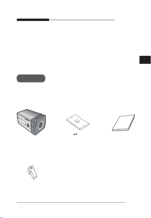
Package
You must check that all the components and accessories listed
below are included in the product package.
E
Camera
Auto Iris Lens
Connector
Camera Holder
(Mount Adaptor)
screw x2
User’s guide
9

Installation and Use Instructions
① There is no user serviceable part inside. So do never
E
disassemble the product.
② Always take caution in handling the product. Do not
put force on or shake the product and make sure to
follow the instructions to avoid possible damage to the
product from an accident.
③ Do not expose it to rain or moisture and keep away
from wet places.
④ Do not use strong abrasives to clean up camera body
and only use a dry cloth to dirt off.
⑤ Do not expose it to direct sunlight and keep it cool.
Otherwise, it can cause a malfunction or an error.
User’s guide
10
User’s guide
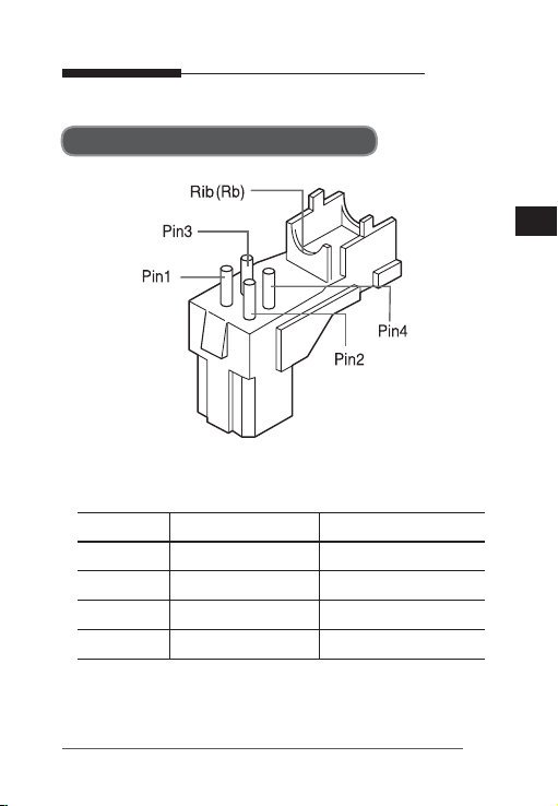
Connect the auto iris lens connector
Remove the sheath round the iris control cable and connect it to
each of the auto iris lens connector as described below.
Pin Number DC Control Type Video Control Type
1 Damp(–) Voltage (+12V)
2 Damp(+) Not Used
3 Drive(+) Video Signal
4 Drive(–) Ground
E
11
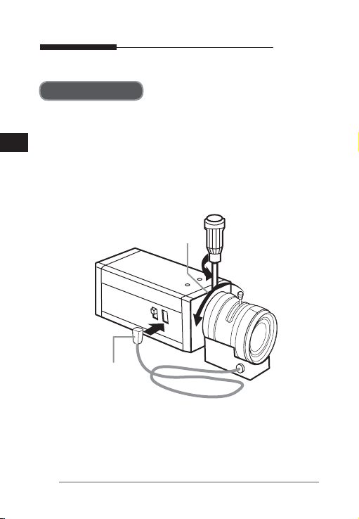
Install the lens
Loosen the single screw on the adjustable ring of the flange
back by turning it anti-clockwise and turn the ring in the “C”
E
direction (anti-clockwise) to the end. Otherwise, it can cause
damage to the internal image sensor or the lens when you
install the lens on the camera.
C direction
Iris Control Cable
User’s guide
12
User’s guide
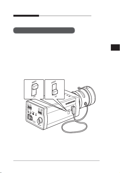
Position the selection switch
You must position the lens selection switch on the side of the
camera, depending on the lens type. If the installed lens is of
DC control type, position the selection switch to “DC” and, for
video control type, switch it to “VIDEO”.
E
13

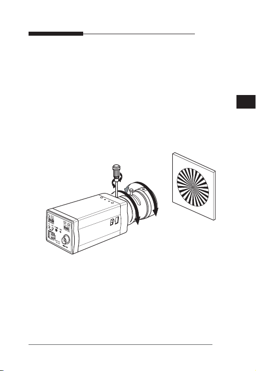
Adjust the back focus
The back focus of a camera is predefined by the factory default.
However, some models are out of focus depending on the lens
E
type. If your camera is out of focus, follow the instructions below
to adjust the back focus. The following is the procedure used to
set the proper back focus point in fixed focus lenses.
Lens without zooming feature
① Capture a sharp subject (with a grid pattern) more than 10m
apart and adjust the focus ring to the infinity (∞).
② Adjust the adjustable ring of the flange back so that you can
capture the sharpest image.
③ Fasten the screw of the adjustable ring of the flange back.
Lens with zooming feature
① Capture a sharp subject (with a grid pattern) 3-5m apart and
adjust the zoom in the TELE (zooming) direction as possible
and also adjust the focus ring so that you can capture the
sharpest image.
② Adjust the zoom in the WIDE direction as possible and
turn the adjustable ring of the flange back so that you can
capture the sharpest image.
③ Repeat ① and ② above 2-3 times to match the focus from
the ZOOM TELE side with that from the ZOOM WIDE side.
User’s guide
14
User’s guide
④ Fasten the screw of the adjustable ring of the flange back.
- If you darken the image before adjusting the focus by
attaching the ND filter to the front of the lens, you can get
a sharper focus.
E
15

Connect the cables and check the operation
1. Connect one end of the BNC cable to the VIDEO OUT port
of the monitor.
E
2. Connect the other end of the BNC cable to the VIDEO In port.
IN
VIDEO IN Terminal on
the rear of moniter
BNC Cable
VIDEO OUT Terminal
3. Connect the camera to the power adaptor. Use a slotted
flat (-) screwdriver to connect one end of the two-line power
adaptor to the DC/AC IN port of the camera.
(GND: marked with a white line on the cable)
- You can plug in to a power outlet regardless of the polarity
for both AC 24V and DC 12V adaptor.
OUT
User’s guide
16

User’s guide
AC24V/DC12V models (SCC-B2311, B2310, B2311P)
AC220V models (SCC-B2011P)
E
17
User’s guide
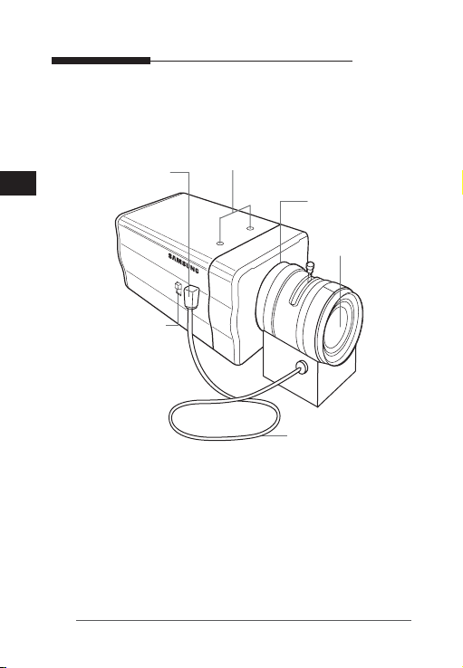
[chapter 4] Parts & Description
① Mount Adaptor Holes
⑥ Auto Iris Lens
④ Flange Back
② Auto Iris Lens
Control Cable
E
⑤ ALC Lens Selection
Switch
③ Auto Iris Lens
Connector
① Mount Adaptor Holes
Used to fix the mount adaptor with a screw if you want to
mount the camera on the bracket.
② Auto Iris Lens (Optional)
A lens to be installed on the camera
If the camera gets dirty on the surface of the lens, apply ethanol to
the provided tissue or a dry cloth and wipe it out.
18
Adjustable Ring

User’s guide
③ Auto Iris Lens Connector
Provides power source and control/ video/DC signal with iris
lens that are required to control the iris of the lens.
④ Flange Back Adjustable Ring
Used to adjust the back focus of the camera.
⑤ ALC Lens Selection Switch
Switch for selecting the type of the lens on the camera.
- DC : position the switch to “DC” if the auto iris lens that
requires the DC control signal is installed on your
camera.
- VIDEO : position the switch to “VIDEO” if the auto iris lens
that requires the video control signal is installed on
your camera.
⑥ Auto Iris Lens Control Cable
Transfers the control signal from the camera to the iris lens.
E
19

User’s guide
AC24V/DC12V Models (SCC-B2311, B2310, B2311P)
E
⑤
③
①
AC220V Models (SCC-B2011P)
⑤
③
⑥
20
⑥
②
⑦
④
②
④
⑦
⑧
①
⑧

User’s guide
① Power Port
Port that is connected to the power (adaptor) cable.
- For SCC-B2311, SCC-B2310 and SCC-2311P
Connects to AC 24V or DC 12V.
- For SCC-B2011P
Connects to AC 230V.
② Power Indication LED
If properly supplied with power, the LED turns on.
③ Vertical Synchronization Phasing Switch (Left)
Used to adjust the vertical synchronization phasing. If pressed,
the vertical synchronization moves to the left.
④ Vertical Synchronization Phasing Switch (Right)
Used to adjust the vertical synchronization phasing. If pressed,
the vertical synchronization moves to the right.
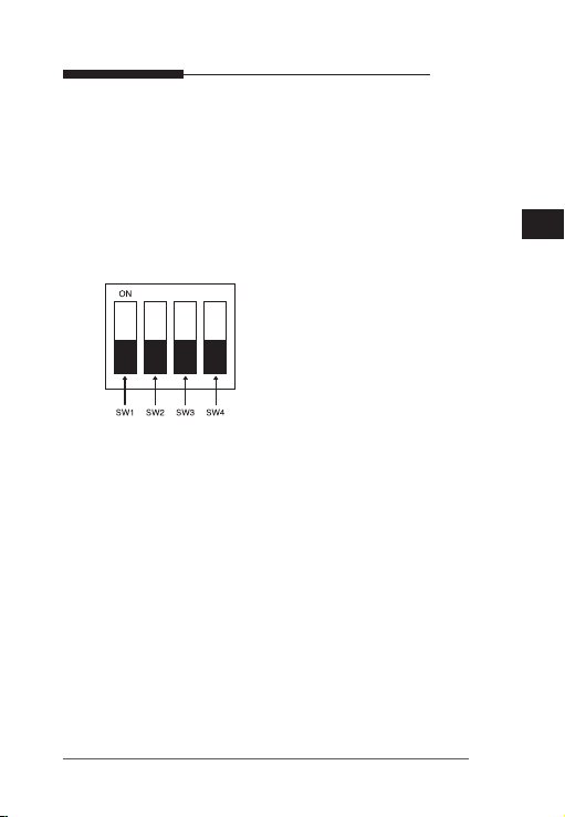
⑤ FUNCTION SWITCH-1
1. L/L
2. ELC
3. FL(Flickerless)
4. LSS
1) SW1 (L/L) :
If set to OFF, it operates in the internal synchronization
mode and if set to ON, it operates in the power
synchronization mode. If multiple cameras are connected
to such as a sequential switcher in auto switch mode, the
E
21

User’s guide
camera in the internal sync mode occurs a skip every time
it moves to other scene. However, this can be solved by
positioning the L/L switch to ON and using the level bar to
E
adjust the vertical sync phasing.
- If your camera uses DC 12V for power source, it operates
in the internal mode regardless of the position (On/Off) of
the L/L switch.
2) SW2(ELC) :
Use this for the manual iris lens. If set to ON, the electronic
shutter speed varies between 1/60 and 1/120,000 second
to keep the screen brightness proper. However, you must
position this switch to OFF if you are using the auto iris
lens (DC or Video control type). Because, in this mode, the
camera can show the color rolling effect when operating
under the mechanical fluorescent lightning. If this happens,
apply the AC power and set the SW1 (L/L) to ON. (NTSC:
60Hz, PAL: 50Hz)
3) SW3 (FL) :
It is an anti-flicker system in 50Hz areas for NTSC and,
in 60Hz areas for PAL that prevents the flickering of the
image due to mismatch between the vertical sync frequency
and the on-off frequency of the lightning. If set to ON, the
electronic shutter speed stays at either 1/100sec (NTSC) or
1/120sec (PAL).
※Note : If SW2 (ELC) is set to ON, the anti-flicker system
does not work even if SW3 is positioned to ON.
22
User’s guide
4) SW4(LSS) :
It is a Sense-Up function that keeps storing the image field
into memory to remove the random noise on the image and
increase the brightness and the contrast ratio. If set to ON,
the camera automatically switches to a maximum of 128
times of storage mode for sharper image.
⑥ FUNCTION SWITCH-2
1. AGC
2. DNR
3. D/N
4. AWB
1) SW1(AGC)
This switch turns on or off the AGC (Auto Gain Control)
function of the camera. If set to ON, the AGC automatically
increases the gain in a low contrast scene of which the iris
couldn’t control the brightness.
2) SW2(DNR)
This switch reduces the random noise on the image. In
particular, this is more effective when the SW4 on the
function switch -1 is set to ON.
3) SW3(D/N)
This indicates the DAY & NIGHT function. If set to ON, the
camera outputs a color image during the daytime and enhances
the color sensitivity of the subject in a low contrast scene,
especially at night by turning off the IR cutoff filter.
23
E

User’s guide
※Note : If SW1 (AGC) is set to OFF, the Day & Night function
does not work even if SW3 is positioned to ON.
E
4) SW4(AWB)
If set to ON, it automatically adjusts the image color
according to the temperature change of the lightning color.
Under a very irregular lightning condition (such as car
headlight), if set to ON, it captures a subject normally (white)
and if set to OFF, it remembers the then normal color temp
to operate at a certain white balance level. Note that AWB
can cause an error in the following conditions. First, if a big
subject of a uniform color with a high saturation exists in the
center of the screen or if few part of the image is in white.
Second, if the lightning is made of special material like
sodium.
⑦ DC IRIS Level Bar
If the ALC lens selection switch is set to DC, use a screwdriver
to adjust the iris level on this bar.
※Note : -
The IRIS range of the DC lens is about between 80IRE and
120IRE. In other words, the DC lens adopts a variable range
limitation system, rather than IRIS Full Open/Close system.
-
Depending on the type of the lens used that allows setting the
value below 75 IRE may cause IRIS hunting. Therefore, make sure
that the range is set to an appropriate level (higher than 80 IRE).
⑧ Video Out Port
Connected to the Video Out port of a monitor. The video signal
is output via this port.
24

Specifications
【 SCC-B2311, SCC-B2310 】
Item Description
Product Type Surveillance Camera
Broadcasting System NTSC STANDARD SYSTEM
Imaging Device 1/3”IT, S-HAD-CCD
Number of Effective
Pixels
Scanning 525 Line, 2:1 interlace
Line Frequency
Synchronous Mode
Horizontal Resolution
S/N Ratio Approx. 50dB
Minimum Subject
Illumination
ALC/ELC
FL(FLICKERLESS) OFF/ON
LSS(SenseUP) OFF/ON (Auto x 128)
DNR OFF/ON
DN (DAYNIGHT) OFF/ON (Auto)
Color Temp ATW(Auto White Balance)/AWC
BLC (Back Light Compensation)
AGC OFF/ON
Signal Out
Power AC24V ±10%(60Hz±0.3Hz), DC12V+10%~-5%
Power Consumption Approx. 3.0 Watts
Temperature -10˚C ~ +50˚C
Moist ~90%
Dimension 65 (W)x 55 (H)x 138 (D)mm(BNC included)
Weight 440 g
SCC-B2311: 768(H) x 494(V)
SCC-B2310: 510(H) x 492(V)
INTERNAL : 15,734Hz(H) 59.94 Hz(V)
LINELOCK : 15,750Hz(H) 60 Hz(V)
INTERNAL
LINE LOCK(AC 24V)
SCC-B2311 : 540 TV Lines
SCC-B2310 : 330 TV Lines
SCC-B2311 : 0.12 Lux (F1.2, 15 IRE, Sense-up off)
0.0009 Lux (F1.2, 15 IRE, Sense-up x 128)
SCC-B2310 : 0.06 Lux (F1.2, 15 IRE, Sense-up off)
0.0005 Lux (F1.2, 15 IRE, Sense-up x 128)
ALC
DC IRIS LENS
VIDEO LENS
ELC
Electronic Shutter Iris(max. 1/120Ksec)
ON
COMPOSITE VIDEO OUT
1V p_p 75Ω / BNC
User’s guide
E
25
 Loading...