

Samsung SCC-B2307P, SCC-B2303P, SCC-B2007P User Manual
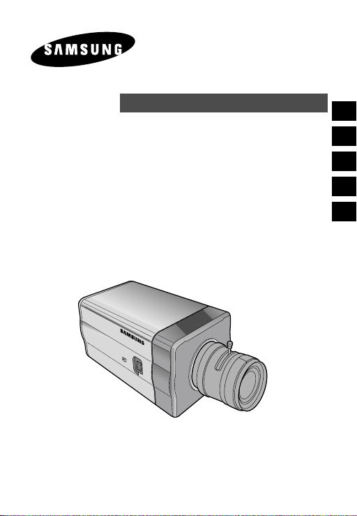
DAY/NIGHT COLOR CAMERA
E
SCC-B2303(P)/B2003P
SCC-B2307P/B2007P
User’s Manual
Es
D
F
I
Important Safety Instructions
CAUTION
E
RISK OF ELECTRIC
SHOCK DO NOT OPEN
CAUTION: TO REDUCE THE
RISK OF ELECTRIC SHOCK,
DO NOT REMOVE REAR
COVER. NO USER
SERVICEABLE PARTS INSIDE.
REFER TO QUALIFIED
SERVICE PERSONNEL.
This symbol indicates
high voltage is present
inside. It is dangerous to
make any kind of contact
with any inside part of
this product.
This symbol alerts you
that important literature
concerning operation and
maintenance has been
included with this
product.
To prevent damage which may result in fire or electric shock hazard,
do not expose this appliance to rain or moisture.
This device complies with part 15 of the FCC Rules. Operation is
subject to the following two conditions.
1) This device may not cause harmful interference, and
2) This device must accept any interference that may cause undesired
operation.
CAUTION:
Danger of explosion if battery is incorrectly replaced.
Replace only with the same or equivalent type recommended by the
manufacturer.
Dispose of used batteries according to the manufacturer’s instructions.
2 3
1. Read these instructions.
2. Keep these instructions.
3. Heed all warnings.
4. Follow all instructions.
5. Do not use this apparatus near water.
6. Clean only with dry cloth.
7. Do not block any ventilation openings. Install in accordance
with the manufacturer’s instructions.
8. Do not install near any heat sources such as radiators, heat
registers, or other apparatus (including amplifiers) that produce
heat.
9. Do not defeat the safety purpose of the polarized or groundingtype plug. A polarized plug has two blades with one wider than
the other. A grounding type plug has two blades and a third
grounding prong. The wide blade or the third prong are
provided for your safety. If the provided plug does not fit into
your outlet, consult an electrician for replacement of the
obsolete outlet.
10. Protect the power cord from being from being walked on or
pinched particularly at plugs, convenience receptacles, and the
point where they exit from the apparatus.
11. Only use attachments/accessories specified by the
manufacturer.
12. Use only with cart, stand, tripod, bracket, or table specified by
the manufacturer, or sold with the apparatus. When a used,
caution when moving the cart/apparatus combination to avoid
injury from tip-over.
13. Unplug this apparatus. When a cart is used, use caution when
moving the cart/apparatus combination to avoid injury from tipover.
14. Refer all servicing to qualified service personnel. Servicing is
required when the apparatus has been damaged in any way,
such as power-supply cord or plug is damaged, liquid has been
spilled or objects have fallen into the apparatus, the apparatus
has been exposed to rain or moisture, does not operate
normally, or been dropped.
E

Contents
Chapter 1 Introduction
Chapter 1 Introduction ........................................................ 5
E
Chapter 2 Special Features ............................................. 6
Chapter 3 Part Names and Functions ............................... 7
Chapter 4 Installation .......................................................... 12
Cautions for Installation and Use .......................13
Connecting Automatic Shutter Lens Connector
Fixing Lens and Adjusting Lens Selection Switch
Adjusting Back Focus ........................................ 16
Connecting Cables ............................................ 18
Chapter 5 Camera Set-Up ................................................. 20
Appendix Product Specification ........................................ 39
NOTE: Avoid aiming the camera directly towards extremely bright
objects such as the sun, as this may damage the CCD image sensor.
........... 14
....... 15
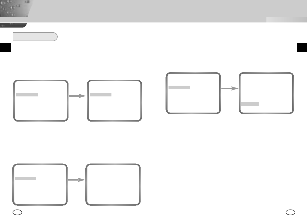
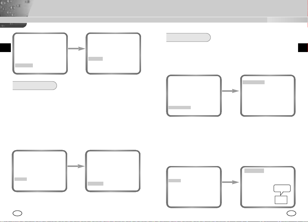
The DAY/NIGHT Camera operates in a color mode in an the
illumination over the standard value and otherwise in B/W mode by
deleting the IR Cut function, which contributes to the improvement
of sensitivity so that it is called a low illumination camera which is
able to identify objects in a dark area. Meanwhile, it has
incorporated a Sense Up function owing to a low speed shutter and
a field accumulation method to improve its low illumination feature
prominently.
[DAY/NIGHT]
It is a function of a color camera to delete the fiter with the
IR Cut function in an illumination below the standard value
so that it has a better sensitivity.
The DAY/NIGHT Camera is mostly used in dark places like
basement parking lots with a comparatively low illumination. In
daytime, it provides a color screen of high density with a horizontal
resolution of 480, and, at night, it utilizes the DAY/NIGHT function
as well as the Sense Up function to identify objects. In same cases,
you may use this camera in relation to the infrared ray emission
equipment additionally.
E
4 5
Chapter 2 Special Features
Chapter 3 Part Names and Functions
High Sensitivity
It has an up-to-date 1/3" Super(EXview)-HAD IT CCD for an image of high
sensitivity.
Low Illumination Function
It has both a low illumination function and DAY/NIGHT function based on
digital signal technology in order to operate in the worst environment
without light.
Digital Zoom Function
It has a digital zoom function for a 10 time enlargement as a maximum. (If
you turn the PIP function to the Digital Zoom mode, the whole screen will
be displayed as a PIP screen.
Superior Back Light Adjustment Function
In case the object has a bright illumination or sunlight behind it, this camera
adjusts the image shaded by the back light for clear photographs.
Digital Power Supply Synchronization Method
The Full Digital Method Line Lock is realized in this camera, which adjusts
the vertical camera synchronization directly to improve controllability and
reliability of the camera.
Resolution
It realizes high resolution resulting from full digital image processing
supported by a state-of-art digital signal technology.
Output Signal Setting
It is able to reverse video output signals and set both a vertical and
horizontal profile.
6 7
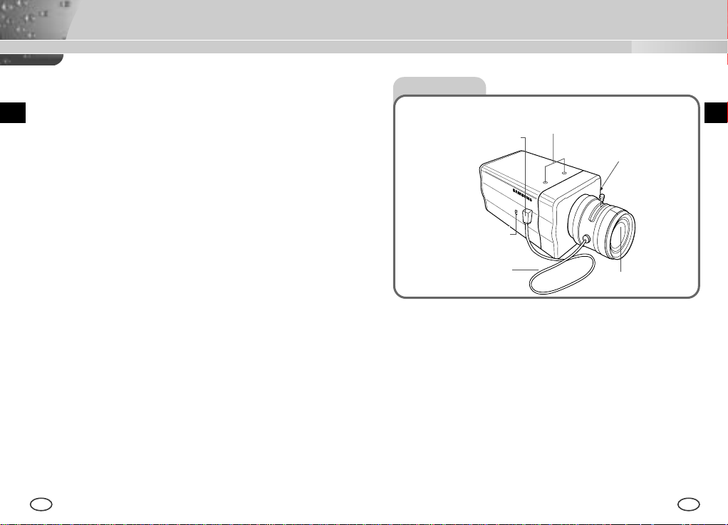
Side View
Mount Adapter Fixing
Auto Iris Lens
Connector
ALC Lens
Selection Switch
Automatic Shutter
Lens Control Cable
Mount Adapter Fixing Groove
This groove is used for screwing the mount adapter, a part of the bracket
where the camera will be installed.
Camera Lens(Option)
This lens is installed in the camera.
* A camera lens with a stained surface should be cleaned softly with a lens
tissue or ethanol painted cotton cloth.
Auto Iris Lens Connector
This connector provides the automatic shutter lens with power supply,
control signal, video signal, or DC signal necessary for the control of the
lens shutter
Groove
Back Focus
Control Bar
Camera Lens
EE
Auto Iris Lens Control Cable
This cable transmits the control signal from the camera to control the lens
shutter.
Back Focus Control Bar
It controls the back focus.
ALC Lens Setting Switch
This switch sets the Auto Iris lens type for use.
DC : When you attach an Auto Iris lens requiring the DC control signal,
please put this switch in the DC position.
VIDEO : When you attach an Auto Iris lens requiring the video control
signal, please put this switch in the VIDEO position.
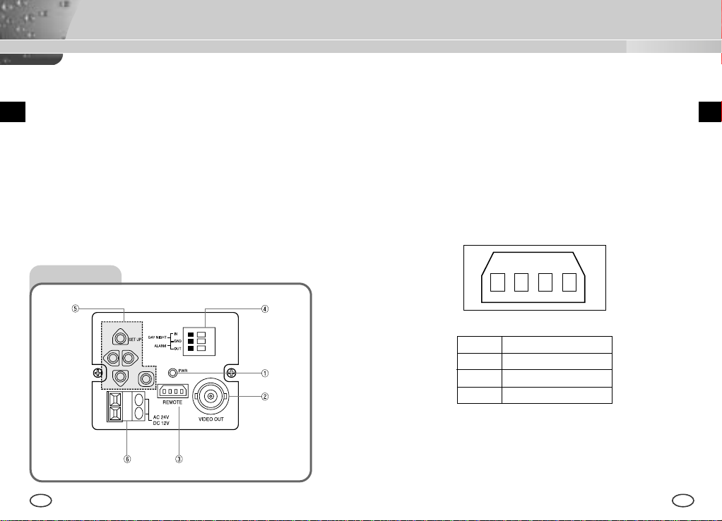
① Power Display LED
When the camera is supplied with power, LED is on.
➁ Video Output Terminal
The monitor video input terminal is connected with this terminal through
which the camera video signal comes out.
➂ Remote Input Terminal(RS-232)
This terminal is used for camera control at the production plant.
EE
Rear View
1
2 3 4
1 TXD
2 RXD
3 +5V
4 GND
8 9
➃ DAY/NIGHT External Signal Input & Alarm Signal Output
This is a function to receive the external DAY/NIGHT signal from the
sensor(option) and convert the signal into BW. The MOTION DET
function generates an alarm signal when a movement is detected.
⑤ Camera Operation Switch(Setup Switch)
The function of the camera operation switch changes depending on
whether the camera is currently in the usual operation mode(No setup
menu is seen on the screen) or the setup menu mode.
EE
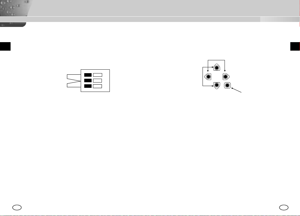
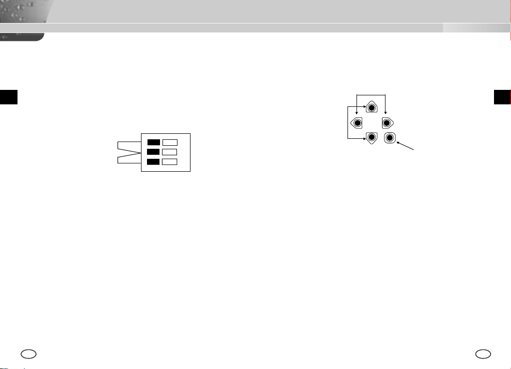
[LEFT/RIGHT] key
[ENTER] key
DAY/NIGHT IN
GND
ALARM OUT
[UP/DOWN] key
①
➁
In the usual operation mode
Connect an external sensor to the DAY/NIGHT terminal as shown in ① then
connect any external device such as a buzzer or lamp to the ALARM
terminal as shown in ➁.
The ALARM output terminal is an open collector with the following capacity:
DC 16V and 100mA.
[LEFT/RIGHT] key : Press key for about 2 seconds and the
menu comes out to control the DC IRIS level. The
[LEFT] key raises the level and the [RIGHT] key
lowers the level.
[ENTER] key : It is used to enter the Setup menu.(Press it about 2
seconds.)
OFF : Open contact
ON : Below 100mA
The DAY/NIGHT input terminal has the input of DC 5V pull-up and over
0.2mA.
OFF : Open contact
In the setup menu mode
[UP/DOWN] key : These keys move up or down the cursor.
[LEFT/RIGHT] key : These keys move the cursor to the left or right or
identify the values sequentially which can be
assigned in each setup menu.
[ENTER] key : It is used to enter a sub-menu of a setup menu by
clicking the setup menu or to set the current value.
ON : Closed contact
➅ Power Connection Port
This port is connected to the power(adapter) cable.
10 11
Chapter 4 Installation
This chapter describes what should be checked before installation, how to
set the installation environment, and what should be done during
installation. Then, it describes how to install the camera and connect the
E
cable in actual circumstances.
What should be done during installation and use
① Do not disassemble the camera on your own.
E
Before Installation
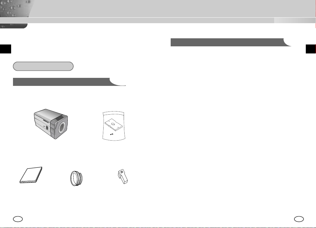
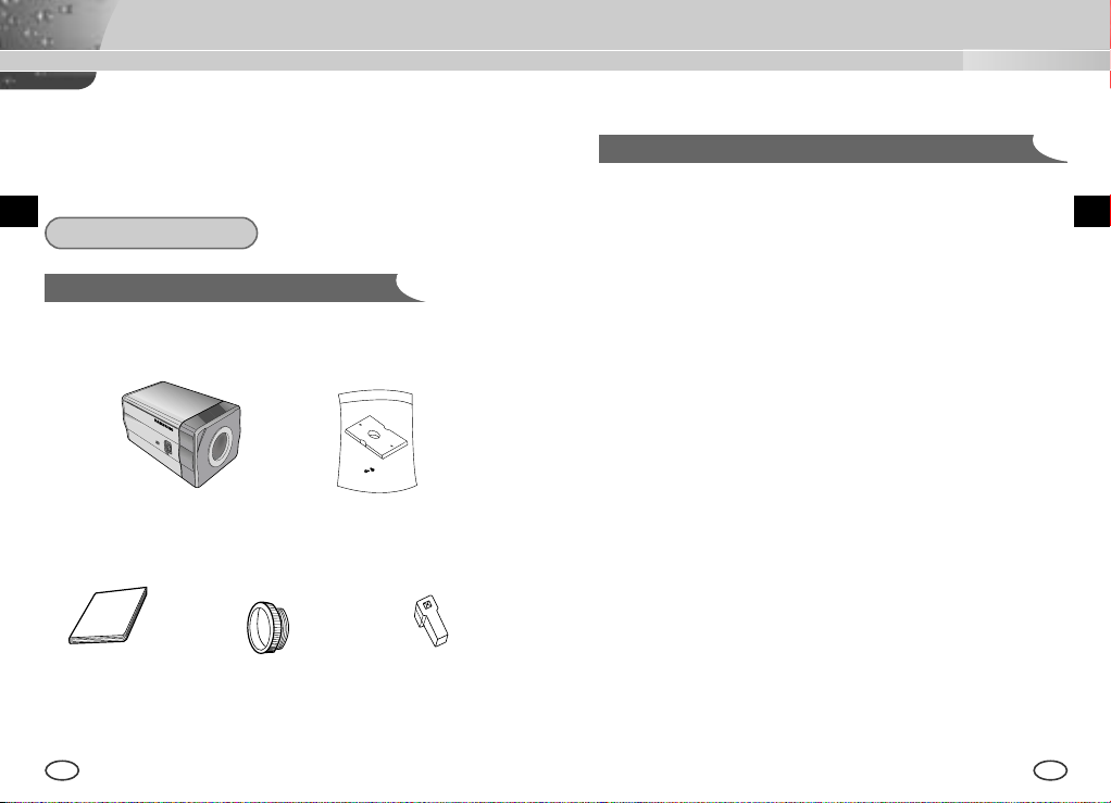
Checking the contents of the package
Be sure to check if the following items are included in the package.
Camera Camera Holder(Mount)
User's Manual
12 13
C Mount Adapter Auto Iris
Lens Connector
➁ Be careful when handling the camera at all times. Do not strike the
camera with your fists or shake it. The camera should be stored and
treated with care to avoid any damage.
➂ Do not put or operate the camera in rain or wet places.
➃ Do not scrub the camera body with rough sandpaper when it is stained.
Please use a dry cloth at all times.
⑤ Put the camera in a cool area free from direct light. Otherwise, the
camera may be damaged.
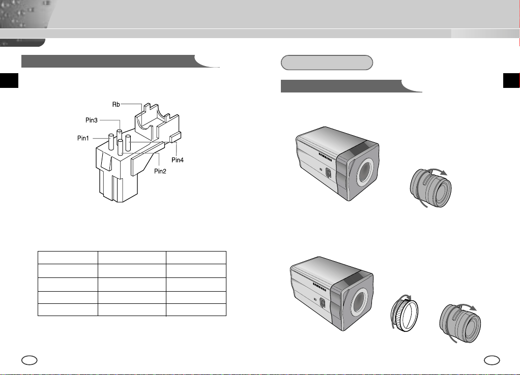
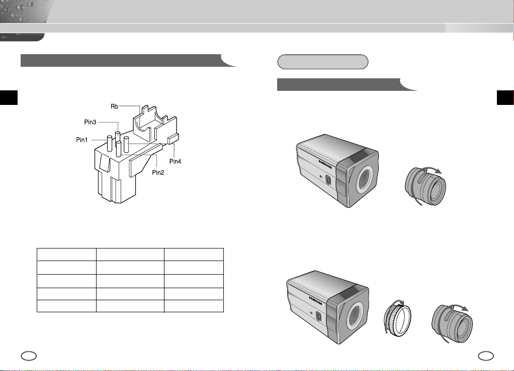
Connecting Auto Iris Lens Connector
Prepare the Auto Iris lens connector, a camera auxiliary, as follows :
Installation
Lens Fixing
In case of CS lenses
Turn the CS lens clockwise until it is fixed as shown as follows.
CS lens
EE
Connect each uncovered shutter control cable wire to the Auto Iris lens
connector as follows.
Pin No. DC Control Type VIDEO Control Type
1 Damp(-) Power (+12V)
2 Damp(+) N/A
3 Drive(+) VIDEO Signal
4 Drive(-) GROUND
14 15
In case of C lenses
Turn the C-mount adapter clockwise to fix it. Then turn the C lens
clockwise until it is fixed as follows.
C lens
Setting Switch Control
You should change the position of the lens setting switch on the side of the
camera according to the lens type. Depending on whether you fixed the DC
control type Auto Iris lens or video control type automatic shutter lens, you
should put the switch in "DC" or "VIDEO" position respectively.
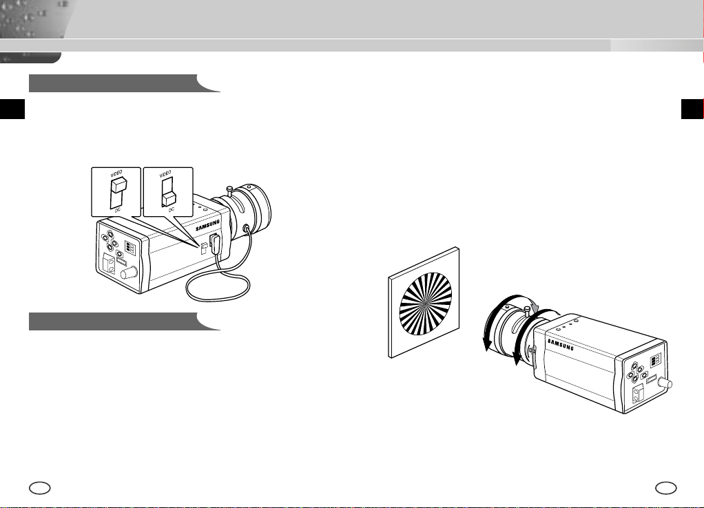
Lenses with zoom function
① Image an object with high resolution(letticed) at a distance of 3 to 5 m
and zoom in the lens as close to TELE as possible. Then adjust the lens
focus bar until the object is seen best.
➁ Zoom in the lens as close to WIDE as possible and adjust the BACK
FOCUS adjustment bar until the object is seen best.
➂ Repeat from ① to ➁ above 2 or 3 times until the focus on the ZOOM
TELE side is in line with that on the ZOOM WIDE side.
Back Focus Adjustment
The camera back focus is adjusted at the plant before delivery, but some
lenses are out of focus though the number differs in types. If it's the case,
you should make the back focus adjustment as follows. First, this is the
back focus adjustment procedure for fixed focus lenses.
Lenses without zoom function
① Image an object with high resolution(letticed) at more than 10m distance
and put the lens focus ring in the infinite(
➁ Rotate the BACK FOCUS control bar until the object is seen best.
➂ Tighten the BACK FOCUS control bar fixing screw.
16 17
) position.
∞
EE
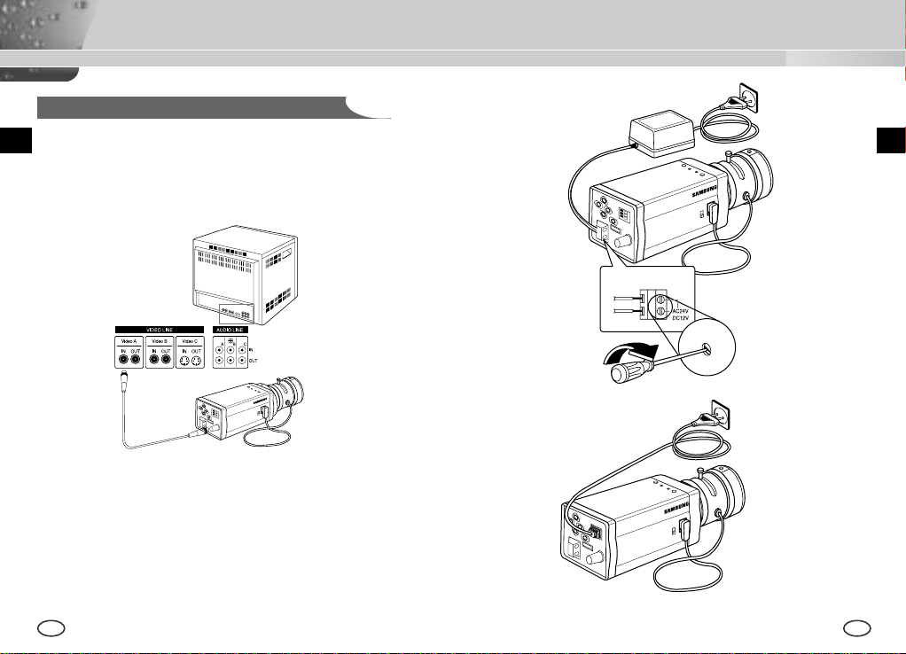
Connecting Cables and Checking Operation
1 First, connect the connector of the BNC cable to the Video Out terminal
2 Second, connect the other connector of the BNC cable to the Video In
terminal.
Video In Terminal of
Monitor Rear Surface
BNC cable
Video Out Terminal
3 Then, connect the power adapter. Connect a part of the power adapter
composed of 2 lines to the Camera Power In terminal with a flat-head
driver as follows.(GND : marked with a white line)
* Power source may be AC24V or DC12V irrespective of polarity
18 19
EE
Chapter 5 Camera Set-Up
This chapter describes how to set up the camera. The first part
describes the whole set up menu and composition and the second part
describes the function of each menu.
E
CAMERA ID
ON.../OFF
IRIS
ALC.../ELC...
BLC
OFF/BOTTOM.../
TOP.../LEFT.../
RIGHT.../
CENTER.../USER..
COLOR/BW
COLOR.../BW.../
AUTO.../EXT...
SHUTTER
OFF/1/100~1/10K
SETUP
MENU
20 21
OFF/AUTO X2~X128
OFF/FIX X2~X128
AGC
OFF/LOW
/HIGH
MOTION
S.SLOW~F.FAST
WHITE BAL
ATW/AWC/MANU...
SYNC
INT/LINE...
SPECIAL
...
EXIT
QUIT/SAVE/PRESET
ON...
ALC...
ELC...
USER...
COLOR...
BW...
EXT...
AUTO...
MANU...
LINE...
3200K/5600K/USER
RED, BLUE SETUP
BAU DRATE D-ZOOM, PIP,
POSI/NEGA,DETAIL,
MOTION DET ON...
SENSITIVITY SETUP
CAMERA ID AND
LOCATION SETUP
DC IRIS SETUP
LEVEL SETUP
AREA SETUP
GAIN, AGC COLOR
SETUP
BURST SETUP
BURST, LEVEL,
DURATION SETUP
PHASE SETUP
MIRROR,
MOTION DET
AREA SETUP
CAMERA ID
This CAMERA ID menu designates a CAMERA ID on the monitor screen
connected to the camera. If you turn on the CAMERA ID menu and press
the [ENTER] key, the sub-screen will appear to designate a CAMERA ID.
The CAMERA ID may be composed of letters, numbers, special texts, or a
combination of these up to 20 digits. The designated CAMERA ID can be
located at any place as desired by using the submenu
CAMERA ID ON...
IRIS ALC...
BLC OFF
COLOR/BW COLOR...
SHUTTER AUTO X8
MOTION F.FAST
WHITE BAL ATW
SYNC INT
SPECIAL ...
EXIT QUIT
press the
[ENTER] key
(CAMERA ID)
A B C D E F G H I J K L
M N O P Q R S T U V W
X Y Z 0 1 2 3 4 5 6 7 8 9
: ! - + * ( ) /
SP
❿❿➛➛
SP
LOCATION...
RET
....................
E
IRIS
This CAMERA has an IRIS function for automatic control of the brightness
level through the intensity of radiation.
❿ ALC
If you select the ALC menu and press the [ENTER] key, the sub-screen
will appear to set the brightness level. Here, you are able to set the
brightness level by pressing the LEFT or RIGHT key in the LEVEL
menu. Level setting is available only by using the DC IRIS lens.
CAMERA ID ON...
IRIS ALC...
BLC OFF
COLOR/BW COLOR...
SHUTTER AUTO X8
MOTION F.FAST
WHITE BAL ATW
SYNC INT
SPECIAL ...
EXIT QUIT
[ENTER] key
(ALC)
press the
DC IRIS (00) ----I---RET
The DC IRIS level setting is available in the SETUP MENU mode as well
as in the operation mode. If you press the LEFT or RIGHT key for about
2 seconds, the DC IRIS Brightness Level setting menu will appear.
Please press the LEFT or RIGHT key to change the mode from EXIT to
SAVE and hit the [ENTER] key to save the file.
DC IRIS (00) ----I---EXIT QUIT
❿ ELC
This menu controls the High Speed Shutter Level within a limited range
in the event of too intensive radiation from outside while using the
Manual Lens. If you select the ELC in the IRIS menu and press the
[ENTER] key, the following subscreen will appear. Here, you are able to
set the level by pressing the LEFT or RIGHT key.
EE
CAMERA ID ON...
IRIS ELC...
BLC OFF
COLOR/BW COLOR...
SHUTTER AUTO X8
MOTION F.FAST
WHITE BAL ATW
SYNC INT
SPECIAL ...
EXIT QUIT
22 23
press the
[ENTER] key
(ELC)
LEVEL (00) ----I---RET
BLC
If you use an ordinary camera when there is an intense and concentrated
illumination behind an object, the back light will shade the image on the
monitor screen. The BLC function prevents such a back light effect to secure
a clear image under all illumination environments. Press the LEFT or RIGHT
key at OFF to set the USER function for a setting of the already set 5 areas
including BOTTOM..., TOP..., LEFT ..., RIGHT..., and CENTER...or USER... for
a direct area setting. If you select the BOTTOM... in the BLC menu and press
the [ENTER] key, you will be able to certify the already set BOTTOM area.
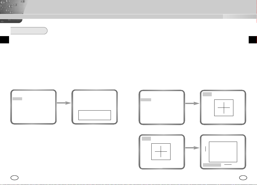
❿ USER AREA
If you select USER... in the BLC menu by using the LEFT or RIGHT key
and press the [ENTER] key, you will be able to determine the size and
location of the BLC area by yourself. When the area is not flashing, you
can specify the area size by pressing the direction keys [LEFT, RIGHT,
UP, or DOWN]. If you press the [ENTER] key when the area is not
flashing, the area will start flashing. Then you can specify the area size
by pressing the direction keys [LEFT, RIGHT, UP, or DOWN]. If you
press the [ENTER] key again, you will escape from the USER AREA
setting menu.
EE
CAMERA ID OFF
IRIS ALC...
BLC
COLOR/BW COLOR...
SHUTTER AUTO X8
MOTION F.FAST
WHITE BAL ATW
SYNC INT
SPECIAL ...
EXIT QUIT
BOTTOM...
press the
[ENTER] key
CAMERA ID OFF
IRIS ALC...
BLC USER...
COLOR/BW COLOR...
SHUTTER AUTO X8
MOTION F.FAST
WHITE BAL ATW
SYNC INT
SPECIAL ...
EXIT QUIT
SIZE..
➛❿
❷
POSITION..
press the
[ENTER] key
press the
[ENTER] key
SIZE..
POSITION..
SIZE..
❷
POSITION..
➛❿
❷
➛❿
24 25
COLOR/BW
The COLOR/BW menu turns the IR(Infrared) Filter on or off. In low
illumination environments, the BW mode will turn off the IR Filter and the
sensitivity will be as high as that of BW cameras. Otherwise, the BW mode
will turn on the IR Filter and the sensitivity will return to normal to recover
the normal screen.
CAMERA ID OFF
IRIS ALC...
BLC OFF
COLOR/BW COLOR...
SHUTTER AUTO X8
MOTION F.FAST
WHITE BAL ATW
SYNC INT
SPECIAL ...
EXIT QUIT
[Left/Right]
❿ COLOR...
This is the IR Filter ON Mode with the normal screen. If you press the
[Enter] key, you will be able to set up the COLOR GAIN LEVEL and
even the AGC COLOR LEVEL while the AGC function is activated.
CAMERA ID OFF
IRIS ALC...
BLC OFF
COLOR/BW BW...
SHUTTER AUTO X8
Use the
MOTION F.FAST
WHITE BAL ATW
SYNC INT
Key
SPECIAL ...
EXIT QUIT
❿ BW...
This is the IR Filter OFF Mode in black and white.(high sensitivity like
BW cameras) If you select the BW... and press the [Enter] key, the BW
submenu screen will appear. You will be able to send out the BURST
signal by turning on or off in this menu.
CAMERA ID OFF
IRIS ALC...
BLC OFF
COLOR/BW BW...
SHUTTER AUTO X8
MOTION F.FAST
WHITE BAL --SYNC INT
SPECIAL ...
EXIT QUIT
press the
[ENTER] key
(BW)
BURST ON
RET
EE
CAMERA ID OFF
IRIS ALC...
BLC OFF
COLOR/BW COLOR...
SHUTTER AUTO X8
MOTION F.FAST
WHITE BAL ATW
SYNC INT
SPECIAL ...
EXIT QUIT
press the
[ENTER] key
(COLOR)
GAIN (0) I-------AGC COLOR (0) ----I----
RET
26 27
❿ AUTO...
This menu automatically converts the COLOR Mode into the BW Mode
or vice versa depending on illumination. In low illumination
environments, it turns off the IR Filter to raise sensitivity, otherwise it
turns on the IR Filter to lower sensitivity.
If you select the AUTO menu and press the [Enter] key, the BW LEVEL
Control AUTO BW submenu will appear on the menu screen. You will be
able to send out the BURST signal by turning on or off in this menu, set
up the DURATION TIME for conversion, or set up the standard
brightness level for converting the COLOR mode into the BW mode.
CAMERA ID OFF
IRIS ALC...
BLC OFF
COLOR/BW AUTO...
SHUTTER AUTO X8
MOTION F.FAST
WHITE BAL ATW
SYNC INT
SPECIAL ...
EXIT QUIT
press the
[ENTER] key
(AUTO BW)
BURST ON
DURATION (30S) -I------LEVEL L---I---H
RET
❿ EXT...
This menu automatically converts the COLOR Mode into the BW Mode
or vice versa depending on illumination with an external sensor. If you
select the EXIT menu and press the [Enter] key, the EXTERNAL BW
submenu will appear on the menu screen. You will be able to send out
the BURST signal by turning on or off in this menu.
CAMERA ID OFF
IRIS ALC...
BLC OFF
COLOR/BW EXT..
SHUTTER AUTO X8
MOTION F.FAST
WHITE BAL ATW
SYNC INT
SPECIAL ...
EXIT QUIT
press the
[ENTER] key
(EXTERNAL BW)
BURST ON
RET
EE
28 29
SHUTTER
The SHUTTER menu sets up the high speed electronic shutter, AUTO
low speed shutter, and FIX low speed shutter. The high speed electronic
shutter covers 7 shutter speeds from 1/100 to 1/10K seconds and is
commonly used for imaging fast moving objects. Both the low speed
shutter and the FIX low speed shutter cover 12 shutter speeds from x2
to x128, which slows the shutter speed to make clearer and brighter the
screen images taken in dark illumination. If you want to slow the shutter
speed automatically depending on the degree of darkness by sensing
the intensity of radiation, please select the AUTO low speed, and if you
want to set up the shutter speed irrespective of the screen brightness,
please set up the menu starting with FIX.
AGC/MOTION
❿ AGC
The AGC menu lightens the screen below the standard brightness
because of the object taken in dark illumination. Setting up the AGC
menu is available only in either High Speed Shutter mode or OFF mode.
If you press the LEFT or RIGHT key to reach the LOW or HIGH position,
the AGC function will start activating. LOW is used for the lower AGC
GAIN whereas HIGH is used for the higher AGC GAIN.
While the COLOR/BW menu is set to AUTO, the AGC menu is all --- and
the maximum AGC GAUN stays at HIGH.
EE
CAMERA ID OFF
IRIS ALC...
BLC OFF
COLOR/BW COLOR...
SHUTTER AUTO X8
MOTION F.FAST
WHITE BAL ATW
SYNC INT
SPECIAL ...
EXIT QUIT
[Left/Right]
CAMERA ID OFF
IRIS ALC...
BLC OFF
COLOR/BW COLOR...
SHUTTER
Use
MOTION F.FAST
WHITE BAL ATW
SYNC INT
Key
SPECIAL ...
EXIT QUIT
AUTO X12
CAMERA ID OFF
IRIS ALC...
BLC OFF
COLOR/BW COLOR...
SHUTTER OFF
AGC OFF
WHITE BAL ATW
SYNC INT
SPECIAL ...
EXIT QUIT
Use
[Left/Right]
Key
CAMERA ID OFF
IRIS ALC...
BLC OFF
COLOR/BW COLOR...
SHUTTER OFF
AGC LOW
WHITE BAL ATW
SYNC INT
SPECIAL ...
EXIT QUIT
If you keep pressing the LEFT or RIGHT key, the following speeds appear
in sequence.
→
OFF → 1/100(NTSC), 1/120(PAL) → 1/250 → 1/500 → 1/1000 → 1/2000
→
1/4000 → 1/10K → OFF → AUTOX2 → AUTOX4 → AUTOX6 → AUTOX8
→
AUTOX12 → AUTOX16 → AUTOX24→ AUTOX32 → AUTOX48
→
AUTOX64 → AUTOX96 → AUTOX128 → OFF → FIXX2 → FIXX4 → FIXX6
→
FIXX8 → FIXX12 → FIXX16 → FIXX24 → FIXX32 → FIXX48 → FIXX64
→
FIXX96 → FIXX128
30 31
❿ MOTION
The MOTION function is available only in the AUTO or FIX mode with
these 5 steps: S.SLOW, SLOW, NORM, FAST, F.FAST.
The S.SLOW minimizes the intensity of the AGC to monitor stable
objects in the dark
The SLOW keeps the intensity of AGC low to monitor objects with a
little movement in the dark.
The NORM standardizes the intensity of AGC to monitor moving
objects in the dark.
The FAST keeps the intensity of AGC high to monitor fast moving
objects in the dark.
The F.FAST maximize the intensity of AGC to monitor very fast
moving objects in the dark.
To activate the MOTION function, you should press the DOWN key to
move the cursor to the MOTION menu and press the LEFT or RIGHT
key while the SHUTTER menu is set to either AUTO or FIX. Pressing the
LEFT and RIGHT key enables you to move to the SLOW mode and
FAST mode respectively
CAMERA ID OFF
IRIS ALC...
BLC OFF
COLOR/BW COLOR...
SHUTTER AUTO X8
MOTION NORM
WHITE BAL ATW
SYNC INT
SPECIAL ...
EXIT QUIT
[Left/Right]
CAMERA ID OFF
IRIS ALC...
BLC OFF
COLOR/BW COLOR...
SHUTTER AUTO X8
Use
MOTION FAST
WHITE BAL ATW
SYNC INT
Key
SPECIAL ...
EXIT QUIT
WHITE BAL
❿ ATW
If you select the ATW mode in the WHITE BAL menu, you will be able to
monitor the color temperature change by real time and set up the White
Balance to the real time color temperature automatically.
❿ AWC
If you select the AWC mode in the WHITE BAL menu, you will be able to
set up the White Balance to the real time color temperature only once
which will be maintained thereafter. If you select the AWC mode in the
WHITE BAL menu, fix a screen that you want to image, and press the
[ENTER] key. Then the AWC function will start activating.
❿ MANU...
If you select the MANU.. mode in the WHITE BAL menu, you will be able
to set up the White Balance in consideration of the current illumination
manually. If you select the MANU... item and press the [ENTER] key, the
MANU... submenu will appear to select the White Balance. If you press
the LEFT or RIGHT key in the PRESET menu, you will be able to select
the 3200K, 5600K, or USER mode.
3200K : Set the color temperature to 3200°K
5600K : Set the color temperature to 5600°K.
USER : Use the RED and BLUE control bar to select a proper value
CAMERA ID OFF
IRIS ALC...
BLC OFF
COLOR/BW COLOR...
SHUTTER AUTO X8
MOTION F.FAST
WHITE BAL MANU...
SYNC INT
SPECIAL ...
EXIT QUIT
for setup.
press the
[ENTER] key
(AWB/MANU)
PRESET 3200K
RET
EE
32 33
(AWB/MANU)
(AWB/MANU)
SPECIAL
You can control the BAUD RATE, D-ZOOM, PIP, MIRROR, POSI/NEGA,
press the
PRESET 3200K
RET
[Left/Right]
BURST OFF(USER)--
key
RED (00) ----I---BLUE (00) ----I---RET
SYNC
The INT mode is necessary for using the internal synchronization and
the LINE... mode is necessary for the operation of multi cameras
because it synchronizes the camera phase by using the external
signal(AC Signal). A little phase deviation for some sets may be aligned
by adjusting the PHASE. The SYNC function is available only with AC
power source. Put the cursor on the LINE..., press the LEFT/RIGHT key
to select the LINE... item, and press the [ENTER] key. Now, you will see
the submenu to adjust the PHASE. The PHASE ranges from -106H to
+106H(NTSC), -138H to +138H(PAL).
CAMERA ID OFF
IRIS ALC...
BLC OFF
COLOR/BW COLOR...
SHUTTER AUTO X8
MOTION F.FAST
WHITE BAL ATW
SYNC LINE...
SPECIAL ...
EXIT QUIT
press the
[ENTER] key
When you use DC power source, the SYNC Menu is full --- and you can
not use the SYNC function.
34 35
(LINE LOCK)
PHASE (000) ----I---RET
DETAIL, and MOTION DET function by yourself in the SPECIAL menu. If
your select the SPECIAL menu and press the [ENTER] key, the SPECIAL
submenu screen will appear.
CAMERA ID OFF
IRIS ALC...
BLC OFF
COLOR/BW COLOR...
SHUTTER AUTO X8
MOTION F.FAST
WHITE BAL ATW
SYNC INT
SPECIAL ...
EXIT QUIT
press the
[ENTER] key
(SPECIAL)
BAUD RATE 38400
D-ZOOM OFF
PIP --MIRROR OFF
POSI/NEGA +
DETAIL (0)---+-MOTION DET OFF
LANGUAGE ENGLISH
RET
❿BAUD RATE : Sets the communication speed to 4800, 9600, 19200, or
38400bps for RS-232 communication.
❿ D-ZOOM : Sets the magnification of the Digital Zoom to the 5 steps, x2,
x4, x6, x8, and x10.
❿ PIP : Picture In Picture function to show a 1/16 screen available only
with the operation of the Digital Zoom. Press the UP, DOWN, LEFT,
or RIGHT key to set up the PIP screen position.
(SPECIAL)
BAUD RATE 38400
D-ZOOM X2
PIP ON...
MIRROR OFF
POSI/NEGA +
DETAIL ( 0)----I-MOTION DET OFF
LANGUAGE ENGLISH
RET
press the
[ENTER] key
POSITION..
PIP Screen
EE
❿ MIRROR : Horizontally flips the video signal.
❿ POSI/NEGA : Outputs the video brightness signal normally or reversely.
❿ DETAIL : Adjusts the horizontal and vertical sharpness.
❿MOTION DET
MOTION DET detects any movement of objects. if you activate the
MOTION DET function at the time when you expect nobody to move, the
function will detect the movement of an intruder Once detected, the
function outputs the ALARM signal. The MOTION DET function detects
any movement and selects the movement sensitivity and the area to
detect the movement. If you select the ON... mode and press the
[ENTER] key, the MOTION DET submenu screen will appear.
❿LANGUAGE : You can choose one of the following languages: English,
German, French, Spanish, and Italian.
(SPECIAL)
BAUD RATE 38400
D-ZOOM OFF
PIP --MIRROR OFF
POSI/NEGA +
DETAIL (0)---I-MOTION DET ON...
LANGUAGE ENGLISH
RET
(SPECIAL)
BAUD RATE 38400
D-ZOOM OFF
PIP --MIRROR OFF
POSI/NEGA +
DETAIL (0)---I-MOTION DET OFF
LANGUAGE ENGLISH
RET
[ENTERt]
[Left/Right]
(MOTION DET)
Press
Key
AREA USER...
SENSITIVITY L---I---H
RET
(SPECIAL)
BAUD RATE 38400
D-ZOOM AUS
BIB --SPIEGEL AUS
Use the
POSI/NEGA +
DETAIL ( 0)----I-AKTIVITAET AUS
Key
SPRACHE DEUTSCH
RET
The AREA menu sets size and position like AREA in the BLC menu. If you
want to select the screen area where the MOTION DET function is applied,
you should press the [ENTER] key in the AREA USER.. by yourself or set
the AREA menu to the PRESET.. Then, the MOTION DET function will be
applied to the selected area of the product during shipment. You can also
move the cursor to the SENSITIVITY menu and press the LEFT or RIGHT
key to set up the detectability of the selected area movement.
(MOTION DET)
AREA USER...
SENSITIVITY L---I---H
RET
SIZE..
➛❿
❷
POSITION..
press the
[ENTER] key
Use the
[ENTER] key
SIZE..
➛❿
POSITION..
SIZE
❷
POSITION..
❷
➛❿
EE
36 37
Product Specification
EXIT
The EXIT menu is used for the termination of the CAMERA SETUP menu.
❿ QUIT
Ignores any change and returns to the previously saved SETUP menu.
❿ SAVE
Saves all the changes to the menu until now.
❿ PRESET
Ignores any change and returns to the initial value of the CAMERA
SETUP menu which was set for the product shipment.
CAMERA ID OFF
IRIS ALC...
BLC OFF
COLOR/BW COLOR...
SHUTTER AUTO X8
MOTION F.FAST
WHITE BAL ATW
SYNC INT
SPECIAL ...
EXIT QUIT
Use the
[Left/Right]
Key
CAMERA ID OFF
IRIS ALC...
BLC OFF
COLOR/BW COLOR...
SHUTTER AUTO X8
MOTION F.FAST
WHITE BAL ATW
SYNC INT
SPECIAL ...
EXIT SAVE
SCC-B2303 Special Features
ITEM DESCRIPTION
Definition CCTV Camera (DAYNIGHT)
Power Source AC 24V ± 10% (NTSC:60Hz ± 0.1Hz),
DC12V +10% ~ -5%
Power Consumption Approx. 4.5W
Broadcasting System NTSC Standard Color System
Imaging Device 1/3 inch IT CCD
Effective Pixel
Scanning Method 525 Line, 2:1 Interlace
Line Frequency Horizontal : 15,734 Hz(INT) / 15,750 Hz(L/L)
Synchronization Method INT/Line Lock
Resolution 500/530 TV Lines (COLOR/BW)
S/N Ratio 52dB (AGC OFF)
Minimum Scene Illumination COLOR :
Day/Night COLOR/BW/AUTO/EXT
Color Temperature ATW/AWC/MANUAL MODE
Electronic Shutter Speed ALC:OFF~1/10K sec (7 steps)
Back Light Compensation
Sense Up OFF/AUTO2X~128X/FIX2X~128X
768(H) X 494(V)
Vertical : 59.94 Hz(INT) / 60 Hz(L/L)
0.3 Lux (F1.2) (0.002 Lux)
B/W :
0.06 Lux (F1.2) (0.0004 Lux)
(3200°K,5600°K,R/B Gain Adjustment)
ELC:Max 1/100K sec
OFF/BOTTOM/TOP/LEFT/RIGHT/CENTER/USER
EE
38 39
Product Specification
ITEM DESCRIPTION
Digital Zoom OFF/ON(X10), PIP
Motion Detection OFF/ON (AREA/SENSITIVITY Setting)
Video Control POSI/NEGA, Mirror(Left/Right), Detailed Setting
Signal Output Composite Video Out : 1.0 Vp-p 75 ohms/BNC
AI Lens VIDEO/DC
Lens Mount CS/C (Mount Adaptor)
Operating Temperature -10°C ~ +50°C
Operating Humidity ~90%
Physical Size 68(W) x 55(H) x 128.5(D) mm
Weight SCC-B2303 : Approx. 450g
SCC-B2303P/B2003P/B2307P/B2007P Special Features
ITEM DESCRIPTION
Definition CCTV Camera (DAYNIGHT)
Power Source SCC-B2303P/B2307P : AC 24V ± 10%
(50Hz ± 0.1Hz), DC12V +10% -5%
SCC-B2003P/B2007P : AC220V ~ AC240V
(50Hz ± 0.1Hz)
Power Consumption SCC-B2303P/B2307P : Approx. 4.5W ,
SCC-B2003P/B2007P : Approx. 5W
Broadcasting System PAL Standard Color System
Imaging Device SCC-B2303P/B2003P:1/3 inch Super HAD CCD
SCC-B2307P/B2007P:1/3 inch EXview HAD CCD
Effective Pixel
Scanning Method 625 Line, 2:1 Interlace
Line Frequency Horizontal : 15,625 Hz(INT) / 15,625 Hz(L/L)
Synchronization Method INT/Line Lock
Resolution 500/530 TV Lines (COLOR/BW)
S/N Ratio 52dB (AGC OFF)
Minimum Scene Illumination SCC-B2303P/B2003P:
752(H) X 582(V)
Vertical : 50 Hz(INT) / 50 Hz(L/L)
COLOR :
0.3 Lux (F1.2) (0.002 Lux)
B/W :
0.06 Lux (F1.2) (0.0004 Lux)
SCC-B2307P/B2007P:
COLOR : 0.2 Lux
B/W : 0.03 Lux
(F1.2) (0.001 Lux)
(F1.2) (0.0002 Lux)
EE
40 41

Item Description
Day/Night COLOR/B/W/AUTO/EXT
E
Color Temperature ATW/AWC/Manual MODE
(3200°K, 5600°K, R/B Gain Adjustment)
Electronic Shutter Speed ALC:OFF~1/10K sec (7 steps)
ELC:Max 1/100K sec
Back Light Compensation
OFF/BOTTOM/TOP/LEFT/RIGHT/CENTER/USER
Sense Up OFF/AUTO2X~128X/FIX2X~128X
Digital Zoom OFF/ON(X10), PIP
Motion Detection OFF/ON (Area/Sensitivity Setting)
Video Control Posi/Nega, Mirror(LEFT/RIGHT), Detailed Setting
Signal Output Composite Video Out : 1.0 Vp-p 75 ohms/BNC
AI Lens VIDEO/DC
Lens Mount CS/C (Mount Adaptor)
Operating Temperature -10°C ~ +50°C
Operating Humidity ~90%
Physical Size 68(W) x 55(H) x 128.5(D) mm
Weight SCC-B2303P/B2307P : Approx. 450g ,
SCC-B2003P/B2007P : Approx. 550g
42
TAG/NACHTFARBE KAMERA
SCC-B2303(P)/B2003P
SCC-B2307P/B2007P
BEDIENUNGSANLEITUNG
D
Sicherheitshinweise
Ziel dieser Informationen ist es, den ordnungsgemäßen Gebrauch dieses Geräts
sicherzustellen und dadurch Gefahren oder Sachbeschädigungen zu vermeiden.
Bitte befolgen Sie alle Anweisungen.
D
1. Achten Sie darauf, dass Sie nur den mitgelieferten Adapter verwenden. (Die
2. Beim Anschließen der Netz- und Signalkabel müssen zuvor die externen
3. Schließen Sie nicht mehrere Kameras an einen Adapter an. (Wird die Kapazität
4. Stecken Sie das Netzkabel fest in die Steckdose ein. (Ein loser Anschluss kann
5. Bei der Wand- oder Deckeninstallation bringen Sie die Kamera sicher und fest an.
6. Plazieren Sie keine leitfähigen Gegenstände (wie z. B. Schraubenzieher, Münzen
7. Die Kamera darf nicht an einem rußigen, staubigen oder feuchten Ort installiert
8. Beim Auftreten eines ungewöhnlichen Geruchs oder einer Rauchentwicklung, die
Warnung
Die Nichtbeachtung eines Warnhinweises kann zum Tode oder
zu schweren Verletzungen führen.
Verwendung eines anderen Adapters als des mitgelieferten kann Feuer, einen
Stromschlag oder die Beschädigung des Geräts verursachen.)
Anschlussbuchsen überprüft werden. Schließen Sie die Alarmsignalkabeladern an
die Alarmanschlüsse, den Netzadapter an die Netzsteckdose und den
Gleichstromadapter an den Gleichstromeingang an, und achten Sie dabei auf die
richrige Polarität. (Ein falscher Anschluss an das Stromnetz kann Feuer, einen
Stromschlag oder die Beschädigung des Geräts verursachen.)
überschritten, kann es zu einer anormalen Wärmeentwicklung oder Feuer
kommen.)
Feuer verursachen.)
(Fällt die Kamera herunter, kann es zur Verletzung von Personen kommen.)
und metallene Objekte) oder mit Wasser gefüllte Behälter auf der Kamera. (Das
kann zur Verletzung von Personen durch Feuer, Stromschlag oder
herunterfallende Gegenstände führen.)
werden. (Andernfalls besteht die Gefahr eines Brandes oder Stromschlags.)
vom Gerät ausgehen, ziehen Sie unverzüglich das Netzkabel aus der Steckdose
und wenden Sie sich an Ihr Kundendienstzentrum. (Die Fortsetzung des
Gebrauchs kann in diesem Fall zu Feuer oder einem elektrischen Schlag führen.)
9. Sollte das Gerät nicht störungfrei funktionieren, setzen Sie sich mit Ihrem Händler
oder dem nächsten Kundendienstzentrum in Verbindung. Das Gerät darf niemals
in keiner Weise zerlegt oder modifiziert werden. (Samsung übernimmt keine
Haftung für Probleme, die durch unbefugte Abänderungen oder einen
Reparaturversuch herbeigeführt sind.)
10. Beim Reinigen darf Wasser niemals direkt auf die Geräteteile gelangen.
(Andernfalls besteht die Gefahr eines Brandes oder Stromschlags.) Die
Oberfläche kann mit einem trockenen Tuch abgewischt werden. Verwenden Sie
für das Gerät keine Reinigungsmittel oder chemischen Reiniger, da sich durch
solche Mittel die Farbe ablösen und der Oberflächenüberzug beschädigt werden
kann.
Achtung
Die Nichtbeachtung eines mit Achtung gekennzeichneten
Hinweises kann zu Verletzungen und Sachschaden führen.
1. Lassen Sie keine Gegenstände auf das Gerät fallen, und setzen Sie es keinen
starken Stößen aus. Setzen Sie die Kamera keinen starken Vibrationen oder
magnetischen Störfeldern aus.
2. Die Kamera darf nicht an Orten mit hohen Temperaturen (über 50 °C) bzw. tiefen
Temperaturen (unter -10 °C) oder hoher Luftfeuchtigkeit installiert werden.
(Andernfalls besteht die Gefahr eines Brandes oder Stromschlags.)
3. Installieren Sie das Gerät nicht in der Nähe von Wärmequellen, wie z. B. einem
Heizgerät oder Heizkörper, und an Orten, an denen es direktem Sonnenlicht
ausgesetzt ist. (Hier besteht Feuergefahr.)
4. Wenn Sie die bereits installierte Kamera an einen anderen Ort verlegen wollen,
achten Sie darauf, die Kamera auszuschalten, bevor Sie sie abnehmen oder neu
installieren.
5. Die Installation sollte an einer gut belüfteten Stelle erfolgen.
6. Ziehen Sie bei einem Gewitter den Netzstecker. (Die Nichtbeachtung kann zu
Feuer oder einer Beschädigung des Geräts führen.)
D
2 3

INHALTVERZEICHNIS
Kapitel 1 Übersicht
Kapitel 1 ÜBERSICHT ....................................................... 5
Kapitel 2 SPEZIALE MERKMALE .................................... 6
D
Kapitel 3 BEZEICHNUNG DER TEILE UND IHRE
FUNKTIONEN .................................................... 7
Die TAG/NACHT Kamera ist eine niedrige Beleuchtung Kamera, die
auch im dunklen Bereich der Gegenstände identifiziert; die Kamera
betreibt in der Farbmode über den bestimmten Beleuchtung und
andernfalls in der SW Mode beseitigt die IR Cut Funktion.
Inzwischen, ist es eine Sense Up Funktion aufgenommen, mit Hilfe
des Langezeit Verschlußes und der Field Anhäufung Methode, um
die Leistung der niedrigen Beleuchtung Eigenschaft zu verbessern.
Kapitel 4 INSTALLA TION ................................................... 12
Vorsichtmaßnahmen für die Installation und den
Gebrauch ............................................................. 13
Verbindung des Automatischen Verschluß
Objektiv Anschlußes .......................................... 14
Einstellung des Objektivs und des Auswahl
Schalters .............................................................. 15
Einstellung des Rück-brennpunktes .................. 16
Anschluß der Kabel ............................................ 18
Kapitel 5 Einstellung der Kamera ...................................... 20
[TAG/NACHT]
Es ist eine Funktion einer Farbkamera; diese Funktion
unter bestimmten Beleuchtung beseitigt den Filter, der eine
IR Cut Funktion hat, um eine bessere Empfindlichkeit zu
haben.
Die TAG/NACHT Kamera ist meistens an der dunklen Stelle, wie am
Untergeschoß-parkplatz benutzt werden. Am Tag, als Farbmode der
hohen Dichte mit einer horizontalen 480 Resolution wird es besorgt,
und an der Nacht die TAG/NACHT Funktion dazu die Sense Up
Funktion wird es nutzen, den Objekt zu identifizieren. Außerdem,
könen Sie diese Kamera zusätzlich in Bezug auf die Infrarot
Emission Geräte benutzen.
Beilage Produkt Spezifikationen ...................................... 39
HINWEIS: Richten Sie die Kamera niemals direkt auf sehr helle Objekte,
wie z. B. die Sonne, da dadurch der CCD-Bildsensor beschädigt werden
kann.
4 5
D
Kapitel 2 Speziale Merkmale
Kapitel 3 Teilnamen und Funktionen
Hohe Empfindlichkeit
Es hat ein neuesten 1/3" Super(EXview)-HAD IT CCD für ein Bild der
hohen Empfindlichkeit.
Niedrige Beleuchtung Funktion
Es hat beide Funktionen; eine Illumination Funktion und TAG/NACHT
funktion auf Grund der Digitalsignal Technologie, um in der schlechten
Umgebung ohne Licht betreiben zu können.
Digitel Zoom Funktion
Es hat eine Digital Zoom Funktion für eine maximun 10mal Vergrößerung.
(Wenn Sie die PIP Funktion zur Digital Zoom Mode wenden, wird das
ganze Bild zum PIP Bild aufgezeigt werden.)
Superior Gegenlicht Einstellung Funktion
Im Fall von einer hellen Beleuchtung oder Sonnenstrahlen hinter dem
Gegenstand kann das Bild, das wegen der Gegenlicht verdunkelt worden
war, deutlich aufgenommen werden.
Digital Stromquelle Synchronisation Methode
Mit dem Vollen Digital Methode Linie Schluß (Line Lock) kann man die
vertikale Synchronisation der Kamera direkt struern, so die Kontrollfähigkeit
und die Zuverläßigkeit der Kamera zu verbessern.
Resolution
Es verwirklicht eine hohe Resolution von vollen digitalen Bild-Entwickellung
mit der höchsten Digital Signal Technologie.
Ausgabe Signal Einstellung
Es ist möglich, das Video Ausgabe Signal umzukehren und eine
vertikalen/horizontalen Profil einzustellen.
Seite Ansicht
Passepartout Adapter
Automatischer Verschluß
Objektiv Anschluß
ALC Objektiv
Auswahlschalter
Automatische Verschluß
Objektive Kontrollkabel
Passepartout Adapter Befestigungsrille
Diese Rille benutzt für die Befestigung des Adapters, ein Teil der Klammer
wo die Kamera installiert wird.
Automatische Verschluß Objektive (Option)
Dieses Objektiv ist in der Kamera installiert werden.
* Eine Objektiv der Oberfläche der Kamera muß mit einem Objektivpapier
oder in Äthan benetzten Baumwolltuch sanft reinigen werden.
Automatischer Verschluß Objektiv Anschluß
Dieser Anschluß versorgt das automatische Verschluß Objektiv mit dem
Strom-versorgung, Kontrollsignal, Videosignal oder DC Signal, nötwendig
für die Kontrolle des Objektiv-verschlußes.
Befestigungsrille
Gegen Brennpunkt (Back
Focus) Kontrollstab
Kamera Objektiv
DD
6 7
Automatische Verschluß Objektiv Kontrollkabel
Diese Kabel senden das Kontrollsignal von der Kamera über, den Objektiv
Verschluß zu kontrollieren.
Gegen Brennpunkt (Back Focus) Kontrollstab
Es kontrolliert das Gegenbrennpunkt.
ALC Objektiv Auswahlschalter
Dieser Schalter stellt für die Verwendung des Auto Blende-blende
Verschluß Typs ein.
DC : Wenn Sie ein Auto Blende-blende Objektiv gebraucht mit dem DC
Kontrollsignal eingestellt haben, wählen Sie dieser Schalter zur DC Position.
VIDEO : Wenn Sie ein Auto Blende-blende Objektiv mit dem VIDEO
Kontrollsignal eingestellt haben, wählen Sie dieser Schalter zur VIDEO
Position.
Vista Posteriore
① Strom Anzeiger LED
Wenn die Kamera mit dem Strom geliefert ist, schaltet LED ein.
➁ Video Ausgabe Terminal
Der Monitor Video Input Terminal ist angeschloßen, mit diesem Terminal,
der durch diesen Terminal das Videosignal der Kamera senden.
➂ Fernbedienung Input Terminal (RS-232)
Dieser Terminal ist für die Kamera Kontrolle an der Produktion Fabrik.
2 3 4
1
1 TXD
2 RXD
3 +5V
4 GND
DD
8 9
➃ TAG/NACHT Außensignal Input ? ALARM Signal Ausgabe
Diese Funktion empfängt das außen TAG/NACHT Signal von dem
Außenlicht Sensor (Option) und zum SW umwandeln lassen.
Die BEWEGUNG DET Funktion führt zu einem ALARM Signal wenn
eine Bewegung wahrgenommen wird.
⑤ Kamera Betriebsschalter (Setup Schalter)
Diese Funkton des Kamera Betriebsschalters ist anhängig von der
Kamera ob sie zur Zeit in der üblichen Mode (kein Setup Menu ist auf
das Bild aufgezeigt) ist, oder in der Setup Menu Mode.
[LINK/RECHTS] Taste
[OBEN/UNTEN] Taste
DD
TAG/NACHT IN
ALARM OUT
GND
①
➁
In der üblichen Betriebsmode
[ENTER] Taste
[LINKS/RECHTS] Taste : Beide Tasten für ca. 2 Sekunden drücken
und das Menu eingeblendet, den DC BLENDE Niveau zu kontrollieren.
Die Taste [LINKS] läßt den Niveau niedrig und die Taste [RECHTS] höher.
Ein Außensensor zum TAG/NACHTTerminal anschließen, wie Nummer ①
zeigt.
Die Äußerengeräte wie ein Summer oder eine Lampe zum ALARM Terminal
anschließen, wie Nummer ➁ zeigt.
Der ALARM Ausgabe Terminal ist ein offene Einnehmer mit dem folgenden
Fassungsvermögen ; DC 16V und 100 mA
AUS (OFF) : Offener Kontakt
EIN (ON) : Unter 100mA
Der TAG/NACHT Input Terminal hat ein Input DC 5V Pull-up, über 0.2mA.
AUS (OFF) : Offener Kontakt
[ENTER] Taste : Es benutzt für die Ausführung des Setup Menus. (Über 2
Sekunden drücken.)
In der Setup Menu Mode
[OBEN/UNTEN] Richtungstaste : Diese Tasten werden bei der Bewegung
des Sursors nach oben oder unten benutzt.
[LINKS/RECHTS] Richtungstaste : Diese Tasten werden bei der Bewegung
des Cursors nach LINKS oder RECHTS benutzt, und auch bei der
Zuweisung in jedem Setup Menu, der Wert Reihenweise zu
identifizieren.
[ENTER] Taste : Diese Taste wird benutzt zu dem Untermenubild gewählt
von dem Setupmenu auszuführen, oder der laufende Wert
einzustellen.
EIN (ON) : Geschloßener KOntakt
➅ Strom Anschluß Terminal
Dieses Terminal wird zum Strom (Adapter)-kabel angeschloßen.
10 11
Kapitel 4 Installation
In diesem Kapitel wird erläutert, was vor der Installation der Kamera zu
beachten ist, wie man eine geeignete Installationsstelle auswählt und
welche Vorsichtsmaßnahmen bei der Installation zu treffen sind. Nun
können Sie die Kamera installieren und die Kabel anschließen.
D
Vor der Installation
Überprüfung des Inhalts in der Verpackung
Überprüfen Sie bitte, ob die folgende Zubehörteile im Lieferumfang
enthalten sind.
Vorsichtsmaßnahmen für die Installation und den Gebrauch
① Der Benutzer darf niemals selber die Kamera demontieren.
➁ Bei dem Umgehen der Kamera immer vorsichtig sein.
Die Kamera nicht mit der Faust schlagen oder schüttern.
Die Kamera muß mit Vorsicht lagert und behandelt werden, vom
Schaden zu vermeinden.
➂ Achten Sie darauf, daß die Kamera an einer regenfreien oder nicht
feuchten Lage installiert werden und an der naßen Lage nicht betreiben
lassen.
➃ Nicht schrubben die Kamera mit dem rauhen Sandpapier und beim
Reinigen benutzen Sie die Trockentücher.
D
Kamera Kamera Stütze
Manuale
d’utenteBedienungs
anleitung
12 13
C Passepartout
Adapter
(Passepartout)
Auto Blende Objektiv
Anschluß
⑤ Installieren Sie die Kamera an einem kühlen Ort und nicht in direkten
Sonnenlicht.
Verbindung des Automatischen Verschluß Objektiv Anschlußes
Der Kamera, dazu der Automatische Verschluß Objektiv Anschluß wie folgt
vorbereiten:
Installation
Einstellung des Objektivs
CS Objektive Fall
Der CS Objektiv im Uhrzeigersinn drehen, bis es wie unten befestigt
wird.
CS Objektive
DD
Jede Abgezogene Verschluß Kontrollkabel Leitung zu dem automatischen
Verschluß Objektiv Anschluß wie folgt verbinden.
Stecknadel Nr. DC Kontrolltyp VIDEO Kontrolltyp
1 Damp(-) Strom (+12V)
2 Damp(+) N/A
3 Drive(+) VIDEO Signal
4 Drive(-) GROUND
14 15
C Objektive Fall
Der C Passepartout Adapter im Uhrzeigersinn drenen, um es zu
befestigen.
Dann drehen der C Objektiv im Uhrzeigersinn, bis es wie unten befestigt
wird.
C Objektive
 Loading...