

Samsung SCC-B2091P, SCC-B2391P, SCC-B2300 User Manual
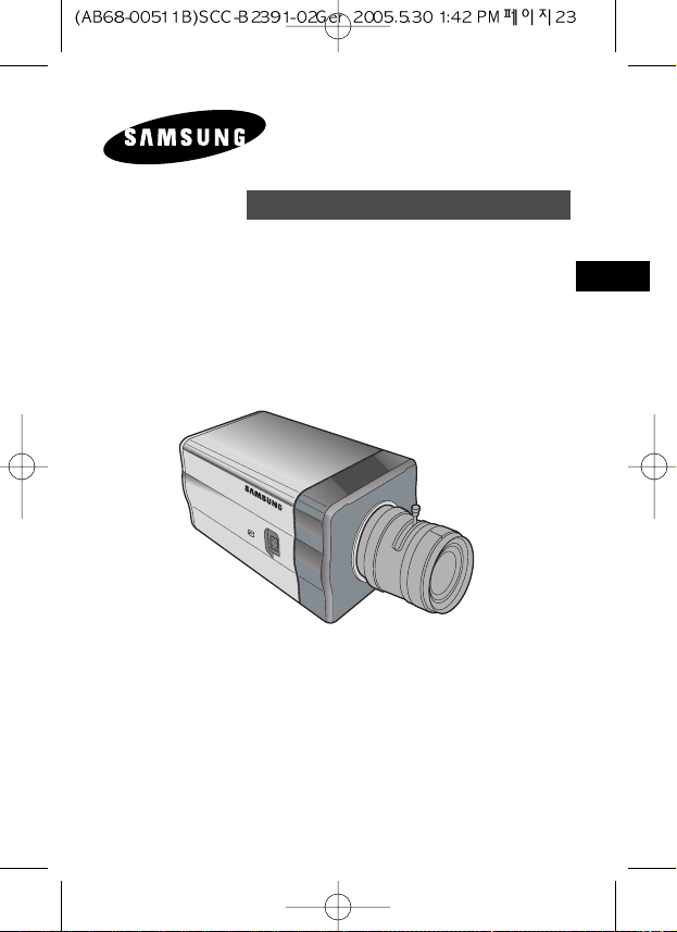
SCC-B2391(P)
SCC-B2091P
SCC-B2300
User’s Manual
DIGITAL COLOR CAMERA
E
D
F
Sp
I
Pl
R
E
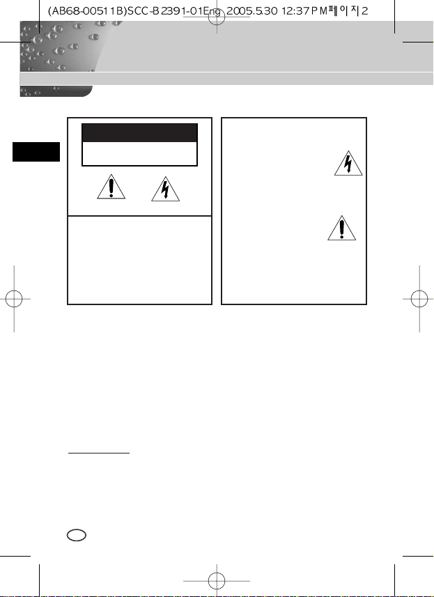
Important Safety Instructions
CAUTION: TO REDUCE THE
RISK OF ELECTRIC SHOCK,
DO NOT REMOVE REAR
COVER. NO USER
SERVICEABLE PARTS INSIDE.
REFER TO QUALIFIED
SERVICE PERSONNEL.
To prevent damage which may result in fire or electric shock hazard,
do not expose this appliance to rain or moisture.
This device complies with part 15 of the FCC Rules. Operation is
subject to the following two conditions.
1) This device may not cause harmful interference, and
2) This device must accept any interference that may cause undesired
operation.
CAUTION:
Danger of explosion if battery is incorrectly replaced.
Replace only with the same or equivalent type recommended by the
manufacturer.
Dispose of used batteries according to the manufacturer’s instructions.
This symbol indicates
high voltage is present
inside. It is dangerous to
make any kind of contact
with any inside part of this
product.
This symbol alerts you
that important literature
concerning operation and
maintenance has been
included with this product.
CAUTION
RISK OF ELECTRIC
SHOCK DO NOT OPEN
2

3
E
1. Read these instructions.
2. Keep these instructions.
3. Heed all warnings.
4. Follow all instructions.
5. Do not use this apparatus near water.
6. Clean only with dry cloth.
7. Do not block any ventilation openings. Install in accordance
with the manufacturer’s instructions.
8. Do not install near any heat sources such as radiators, heat
registers, or other apparatus (including amplifiers) that produce
heat.
9. Do not defeat the safety purpose of the polarized or groundingtype plug. A polarized plug has two blades with one wider than
the other. A grounding type plug has two blades and a third
grounding prong. The wide blade or the third prong are provided
for your safety. If the provided plug does not fit into your outlet,
consult an electrician for replacement of the obsolete outlet.
10. Protect the power cord from being from being walked on or
pinched particularly at plugs, convenience receptacles, and the
point where they exit from the apparatus.
11. Only use attachments/accessories specified by the manufacturer.
12. Use only with cart, stand, tripod, bracket, or table specified by
the manufacturer, or sold with the apparatus. When a used,
caution when moving the cart/apparatus combination to avoid
injury from tip-over.
13. Unplug this apparatus. When a cart is used, use caution when
moving the cart/apparatus combination to avoid injury from tipover.
14. Refer all servicing to qualified service personnel. Servicing is
required when the apparatus has been damaged in any way,
such as power-supply cord or plug is damaged, liquid has been
spilled or objects have fallen into the apparatus, the apparatus
has been exposed to rain or moisture, does not operate
normally, or been dropped.
4
E
Chapter 1 Introduction ........................................................ 5
Chapter 2 Special Features ............................................. 6
Chapter 3 Installation ........................................................... 7
Checking the contents of the package .............. 7
Precautions in Installation and Use ................... 8
Connecting Auto Iris Lens Connector ................ 9
Lens Fixing
........................................................... 10
Setting Lens Selection Switch
.................... 11
Back Focus Adjustment
................................ 11
Connecting Cables and Checking Operation ....... 13
Chapter 4 Part Names and Functions ............................... 15
Product Specification ........................................ 20
Contents
5
E
DAYNIGHT camera is a low brightness camera, which improves the sensitivity
by operating with a color mode at the over of regular brightness and operated
with a B/W mode by canceling the IR Cut function at the below of regular
brightness. Also, it can be used linked with the separated infrared ray emission
device. SCC-B2391(P)/B2091P has a high resolution with the 540 TV Lines of
horizontal resolution through the digital signal processing and OLPF.
❉
In the mechanical fluorescent light environment, if you attach MANUAL IRIS
LENS and turn the ELC switch among FUNCTION switches on, color may be
rolled.
In this case, supply AC power before you turn L/L switch among FUNCTION
switches on. (NTSC:60HZ , PAL:50HZ)
Chapter 1 Introduction
[DAYNIGHT]
It is a function of a color camera to delete the fiter with
the IR Cut function in an illumination below the standard
value so that it has a better sensitivity.
COLOR ROLLING is the problem that color on the
monitor screen changes non-periodically.
This happens when White Balance is not fixed,
because a mechanical fluorescent light flickers
when it’s cycle is the same to the cycle of the power
frequency.

6
E
High Sensitivity
It has an up-to-date 1/3" Super-HAD IT CCD for an image of high sensitivity.
Resolution
It realizes high resolution resulting from full digital image processing
supported by a state-of-art digital signal technology.
Superior Back Light Adjustment Function
In case the object has a bright illumination or sunlight behind it, this camera
adjusts the image shaded by the back light for clear photographs.
Digital Power Supply Synchronization Method
The Full Digital Method Line Lock is realized in this camera, which adjusts
the vertical camera synchronization directly to improve controllability and
reliability of the camera.
Chapter 2 Special Features
7
E
This chapter describes what should be checked before installation, how to
set the installation environment, and what should be done during installation.
Then, it describes how to install the camera and connect the cable in actual
circumstances.
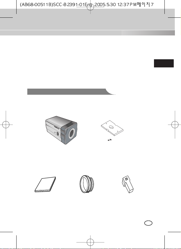
Camera
Holder(Mount)
C Mount Adapter
Chapter 3 Installation
Auto Iris
Lens Connector
User's Manual
Camera
Be sure to check if the following items are included in the package.
Checking the contents of the package
8
E
① Do not attempt to disassemble the camera yourself.
➁ Be cautious in handling the camera. Avoid striking or shaking the
camera. Be cautious to avoid damage on the camera caused by improper
storage or operation.
➂ Do not expose this camera to rain or moisture. Do not operate this
camera on a wet place.
➃ Do not use strong or abrasive detergents when cleaning the camera
body. Use a dry cloth to clean the camera.
⑤ Keep the camera at a cool place away from the direct sunlight. Leaving it
under the direct sunlight may result in the malfunction of the unit.
Precautions in Installation and Use
9
E
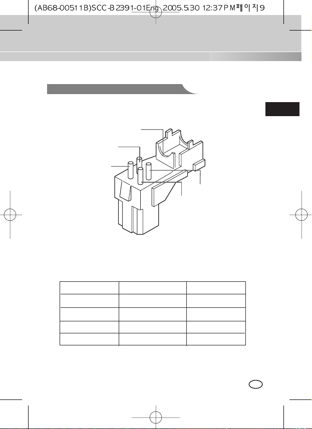
Connecting Auto Iris Lens Connector
Prepare the following Auto Iris Lens Connector supplied with the camera.
Connect the cable of the control cable, whose covering is stripped, to the
Auto Iris Lens Connector as shown below.
Rb
Pin3
Pin2
Pin4
Pin1
Pin No. DC Control Type VIDEO Control Type
1 Damp(-) Power (+12V)
2 Damp(+) N/A
3 Drive(+) VIDEO Signal
4 Drive(-) GROUND
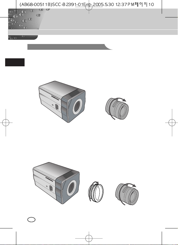
In case of CS lenses
Turn the CS lens clockwise until it is fixed as shown as follows.
In case of C lenses
Turn the C-mount adapter clockwise to fix it. Then turn the C lens
clockwise until it is fixed as follows.
Lens Fixing
CS lens
C lens
10
E
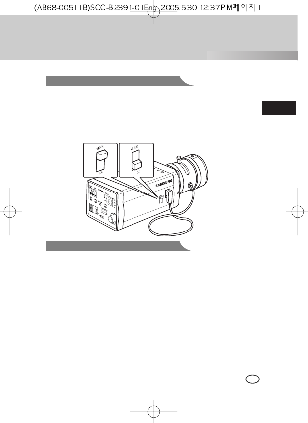
Setting Lens Selection Switch
11
E
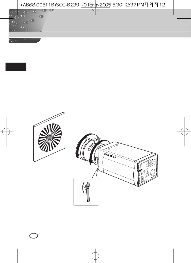
Back Focus Adjustment
The camera back focus is adjusted at the plant before delivery, but some
lenses are out of focus though the number differs in types. If it's the case,
you should make the back focus adjustment as follows. First, this is the back
focus adjustment procedure for fixed focus lenses.
Lenses without zoom function
① Image an object with high resolution(letticed) at more than 10m distance
and put the lens focus ring in the infinite(
∞
) position.
➁ Rotate the BACK FOCUS control bar until the object is seen best.
➂ Tighten the BACK FOCUS control bar fixing screw.
When lens mounting is completed, set the Lens selection Switch on the side
of the camera according to the mounted lens type. When the mounted lens
is an Auto Iris Lens of the DC control type, set the Lens Selection Switch to
"DC". When the mounted lens is an Auto Iris Lens of the Video control type,
set the Lens Selection Switch to "VIDEO".
12
E
Lenses with zoom function
① Image an object with high resolution(letticed) at a distance of 3 to 5 m
and zoom in the lens as close to TELE as possible. Then adjust the lens
focus bar until the object is seen best.
➁ Zoom in the lens as close to WIDE as possible and adjust the BACK
FOCUS adjustment bar until the object is seen best.
➂ Repeat from ①to ➁ above 2 or 3 times until the focus on the ZOOM
TELE side is in line with that on the ZOOM WIDE side.
BACK FOCUS
CONTROL BAR
Connecting Cables and Checking Operation
13
E
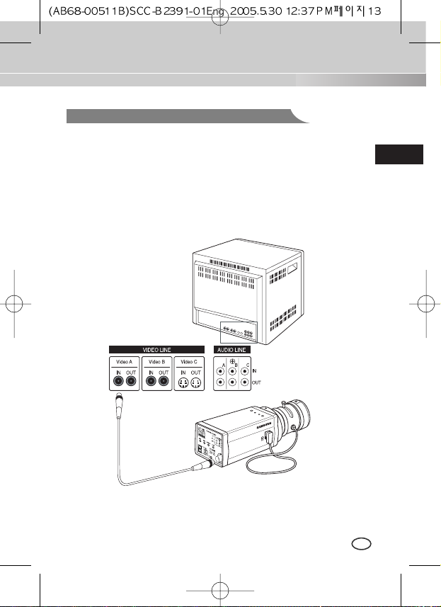
1 First, connect the connector of the BNC cable to the Video Out terminal
2 Second, connect the other connector of the BNC cable to the Video In
terminal.
BNC cable
Video Out Terminal
Video In Terminal of
Monitor Rear Surface
14
E
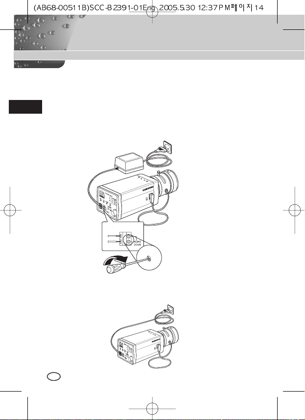
3 Third, connect the power cable.
① AC24V/DC12V Power Input Camera.
Connect 2 lines of the power adapter using a screwdriver to the power
IN Terminal of the camera as shown below.
❉
Without the distinction of the polarity, connect to the AC24V or DC12V
power source.
➁ AC230V Power Input Camera
Connect the power input cord to the AC230V power source.
15
E
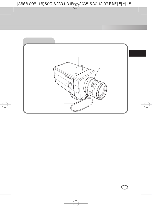
Chapter 4 Part Names and Functions
Side View
①
Mount Adapter Fixing Groove
This groove is used for screwing the mount adapter, a part of the bracket where the
camera will be installed.
➁
Camera Lens(Option)
This lens is installed in the camera.
❉
A camera lens with a stained surface should be cleaned softly with a lens
tissue or ethanol painted cotton cloth.
➂
Auto Iris Lens Connector
This connector provides the automatic shutter lens with power supply, control signal,
video signal, or DC signal necessary for the control of the lens shutter.
➃
Auto Iris Lens Control Cable
This cable transmits signal which controls the Iris.
⑤
ALC Lens Selection Switch
This Switch is used for select the type of Lens.
➅
Back Focus Control Bar
This bar is used for set back focus of the camera.
➃
Auto Iris Lens
Control Cable
⑤
ALC Lens
Selection Switch
➂
Auto Iris Lens
Connector
①
Mount Adapter Fixing
Groove
➅
Back Focus
Control Bar
➁
Camera Lens
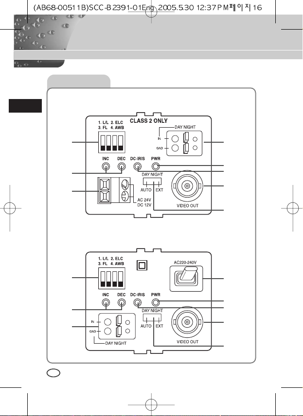
Rear View
16
E
AC24V/DC12V Camera (SCC-B2391(P)/B2300)
AC230V Camera (SCC-B2091P)
⑤
⑤
⑦
⑧
⑨
➁
➅
⑦
⑧
①
①
⑨
➂ ➃
➂ ➃
➁
➅
17
E
① Power connection port
AC24V/DC12V Camera : It is a port connected to the power adaptor cable.
AC230V Camera : It is Power cord.
➁ POWER LED
If the power of a camera is supplied normally, the LED is ON.
➂➃INC and DEC Switch
Both switches increase or decrease the profit of RED and BLUE to fix a color
temperature as you wish while AWB among the FUNCTION switches is
off(USER) and control the vertical synchronous phase while both AWB and
L/L are on.
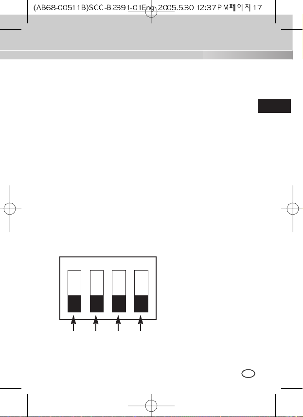
⑤ FUNCTION Switch
1. L/L 2. ELC
3. FL 4. AWB
SW1 SW2 SW3 SW4
ON
18
E
1) SW1(L/L) :
Set to OFF, the camera activates the internal synchronization mode and set to ON, the power
synchronization mode. If you connect multi cameras to the sequential switcher to enter the
automatic conversion mode, the screen will bounce every screen while the camera stays in
INT(internal synchronization). Such bouncing phenomena may be cleared and screen conversion
becomes smooth by setting the L/L switch to ON and using the INT/DEC switch to control the
vertical synchronous phase.
❉
If you want to control the vertical synchronous phase with the INT/DEC switch when L/L is set
to ON, you shall set SW4 to AWB ON.
❉
In case of DC12V, INT(internal synchronizer) will be fixed without regard to ON/OFF of L/L.
2) SW2(ELC) :
Use this switch with the Manual Iris Lens. While this switch is ON, the speed of the electronic
shutter varies with the brightness of the subject from 1/60(50) to 1/100,000 sec for automatically
controlling the brightness of the screen. However, with the Auto Iris Lens (DC or Video Control),
be sure to switch OFF.
Color Rolling may occur in this mode. In that case, input AC power source to the camera and
select SW1 "ON".
(NTSC : 60HZ, PAL : 50HZ)
3) SW3(FL):
This is to prevent flicker on the screen when NTSC system is used in 50HZ power supply region
and PAL system is used in 60HZ power supply region. That is to prevent shaking on the
screen resulted from the discordance of the vertical sync frequency and the flicker frequency of
the illumination. While this switch is ON, the electronic shutter is fixed to 1/100sec (NTSC) or
1/120 sec (PAL).
4) SW4(AWB):
When setting up ON, the color of screen is adjusted automatically in accordance with the change
of lighting color temperature by the change of outer environment. (ATW) If the lighting condition is
steady, OFF setting is available. The camera memorizes the lighting color temperature at the
time when the switch setting is changed from ON to OFF, and the camera color is adjusted to the
memorized color temperature. (AWC) If the lighting color temperature is changed and you want
to make the camera be memorized/operated with the changed color temperature, re-operate the
switch On/Off operation. However, be aware that an error may occur under the following
conditions.
First, a case that the subject is big, single color of the high chroma, and in the center of
the screen or a case with almost no white color on the screen.
Second, a case with a specific illumination such as a natrium lamp
19
E
➅
DC IRIS Level Controller
When the ALC lens selection switch is set to DC, use the same control bar as the
driver to control the IRIS level.
⑦
Video Output Port
This port shall be connected to the monitor video input port or equivalent. You
may output camera video signals through this port.
⑧
DAYNIGHT Selection Switch
If you set this switch to AUTO, the DAYNIGHT function will be automatically
activated according to the illumination. Under poor illumination, IR Filter will be
automatically eliminated in the black and white mode(BW Mode) to raise the
sensitivity but under good illumination, IR Filter will be automatically inserted in
the color mode(COLOR Mode).
IR Filter responds to the preset Duration Time (Delivery Condition:10 seconds).
When you convert DAYNIGHT in the AUTO mode, you shall set Duration Time
as follows. (Please turn off the L/L switch and the AWB switch to begin with).
Whenever you convert the DAYNIGHT selection switch from EXT to AUTO while
you hold on to the INC/DEC switch, DURATION TIME becomes 10s, 30s, 60s,
90s, 120s, and 150s in sequence. Upon setup, you shall cancel pressing the
INC/DEC switch to save the setup condition in the camera. Upon saving, the
DAYNIGHT mode will be automatically converted depending on DURATION
TIME even in the event of POWER On/Off.
For resetting, please repeat the above procedure. (Upon resetting, you may r
eturn both L/L and AWB to the previous condition.)
If you set this switch to EXT, COLOR/BW Mode varies depending on the external
signal input to the DAYNIGHT external signal input port(
⑨
).
⑨
DAYNIGHT External Signal Input Port
When the DAYNIGHT selection switch(⑧) is set to EXT, COLOR/BW Mode
varies depending on the input signal to this port.
The input terminal shall be DC5V pull-up input and over 0.2mA.
OFF : Open contact
ON : Closed contact

20
E
Product Specification
SCC-B2391P/2091P
ITEM
Contents
Product Type CCTV Camera
Broadcasting System PAL STANDARD SYSTEM
CCD 1/3 Super-HAD CCD
Effective Pixels 752(H) x 582(V)
Scanning Type 625 Line, 2:1 Interlace
INTERNAL : 15,625Hz(H)
50 Hz(V)
LINE LOCK :
15,625Hz(H)
50 Hz(V)
INTERNAL
LINE LOCK(When AC Power source is used)
Resolution(H) 540(Color)/570(B/W) TV Lines
S/N Ratio About 50dB
DAYNIGHT AUTO / EXT
Frequency
Sync Type
Minimum Illumination
of Object
0.3 Lux(Color) / 0.06 Lux(B/W)
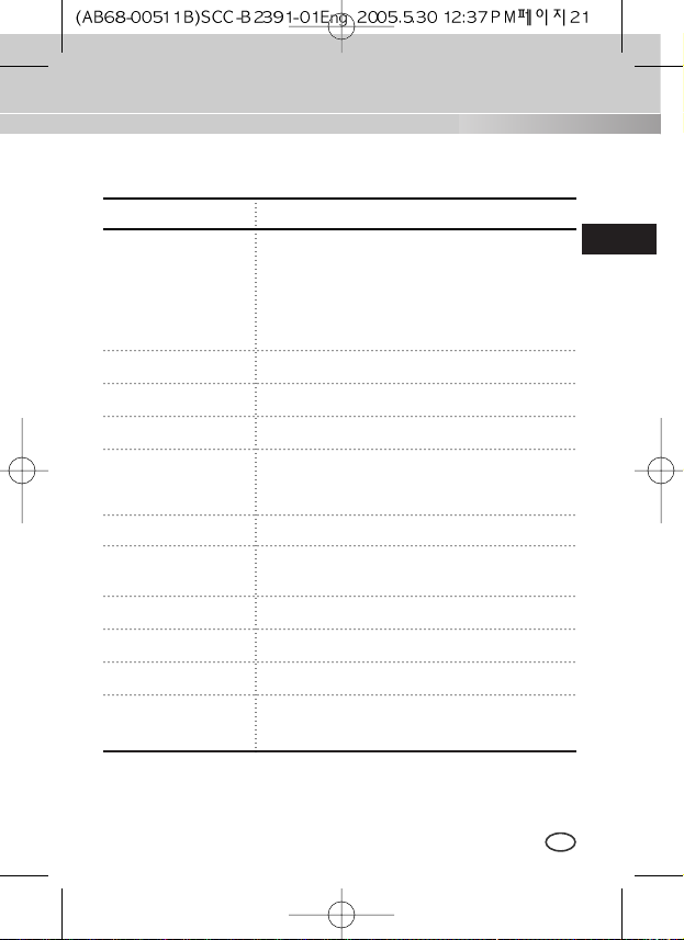
ITEM
Contents
ALC
DC IRIS LENS
ALC/ELC VIDEO LENS
ELC
Electronic Shutter Iris Function (Max. 1/100 Ksec)
Color Temperature
AWB/MANUAL
BLC
ON
AGC ON
Video Output
COMPOSITE VIDEO OUT
1V p_p 75Ω/BNC
Operating Temp
-10°C~+50
°C
Operating Humidity
~90%
Size 68(W)x55(H)x128.5(D)mm(included BNC)
21
E
Power Source
AC24V ±10%(50Hz±0.3Hz), DC12V+10%~-5%
Power Consumption
B2391P : About 3W
B2091P : About 4W
Weight
B2391P :
450g
B2091P : 550g
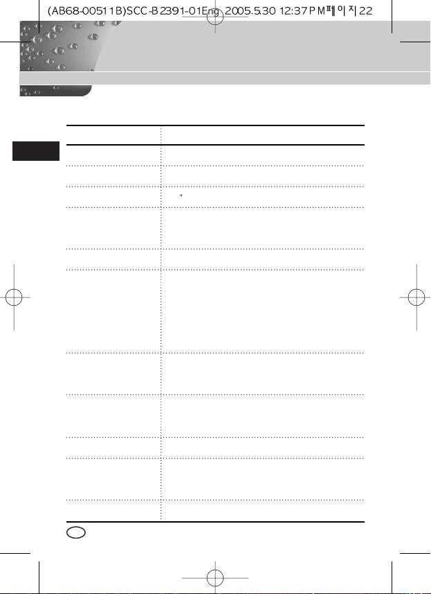
ITEM
Contents
Product Type CCTV Camera
Broadcasting System NTSC STANDARD SYSTEM
CCD 1/3 Super-HAD CCD
Effective Pixels
B2391 :
768(H) x 494(V)
B2300 :
510(H) x 492(V)
Scanning Type 525 Line, 2:1 Interlace
INTERNAL : 15,734Hz(H)
59.94 Hz(V)
LINE LOCK : 15,750Hz(H)
60 Hz(V)
INTERNAL
LINE LOCK(When AC Power source is used)
Resolution(H) B2391 : 540(Color)/570(B/W) TV Lines
B2300 : 400(Color)/420(B/W) TV Lines
S/N Ratio About 50dB(AGC OFF)
DAYNIGHT AUTO / EXT
22
E
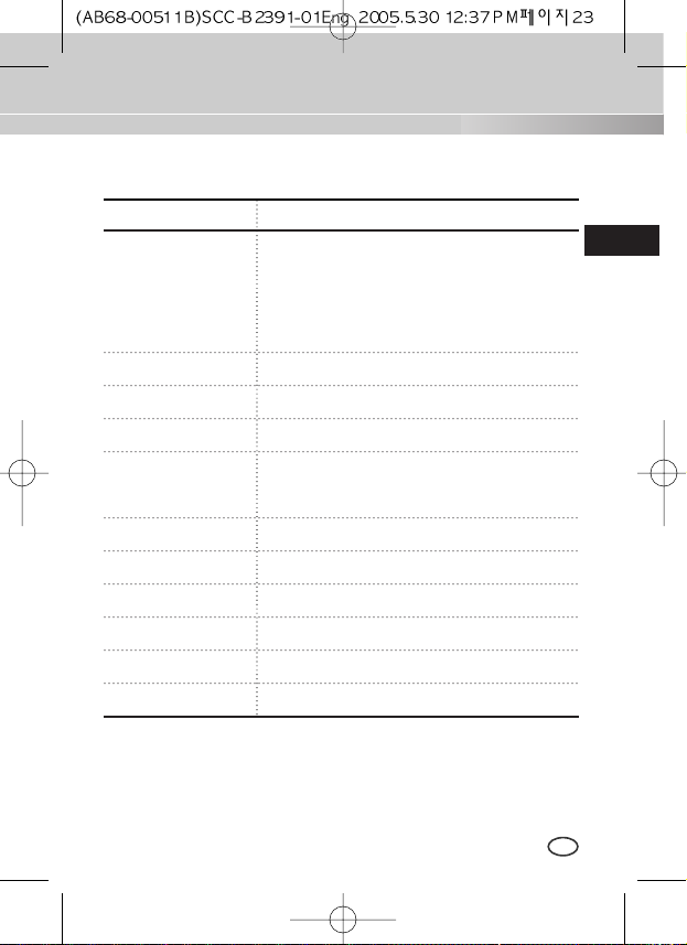
SCC-B2391/B2300
Frequency
Sync Type
Minimum Illumination
of Object
B2391 : 0.3 (Color) / 0.06 (B/W)Lux
B2300 : 0.2 (Color) / 0.03 (B/W)Lux
Product Specification
23
E
ITEM
Contents
ALC
DC IRIS LENS
ALC/ELC VIDEO LENS
ELC
Electronic Shutter Iris Function (Max. 1/100 Ksec)
Color Temperature
AWB/MANUAL
BLC
ON
AGC ON
Video Output
COMPOSITE VIDEO OUT
1V p_p 75Ω/BNC
AC24V ±10%(60Hz±0.3Hz), DC12V+10%~-5%
Power Consumption About 3Watts
Operating Temp
-10°C~+50
°C
Operating Humidity
~90%
Size 68(W)x55(H)x128.5(D)mm(included BNC)
Weight
450g
Power Source
Part No.:AB68-00511B
Correct Disposal of This Product
(Waste Electrical & Electronic Equipment)
(Applicable in the European Union and other European countries with separate collection systems)
This marking shown on the product or its literature, indicates that it should not be disposed with other
household wastes at the end of its working life. To prevent possible harm to the environment or human
health from uncontrolled waste disposal, please separate this from other types of wastes and recycle it
responsibly to promote the sustainable reuse of material resources.
Household users should contact either the retailer where they purchased this product, or their local
government office, for details of where and how they can take this item for environmentally safe recycling.
Business users should contact their supplier and check the terms and conditions of the purchase contract.
This product should not be mixed with other commercial wastes for disposal.
BEDIENUNGSANLEITUNG
DIGITAL FARBE KAMERA
D
SCC-B2391(P)
SCC-B2091P
SCC-B2300
D
Ziel dieser Informationen ist es, den ordnungsgemäßen Gebrauch dieses
Geräts sicherzustellen und dadurch Gefahren oder Sachbeschädigungen zu
vermeiden. Bitte befolgen Sie alle Anweisungen.
Sicherheitshinweise
Warnung
Warnung
Achtung
1. Achten Sie darauf, dass Sie nur den mitgelieferten Adapter verwenden. (Die
Verwendung eines anderen Adapters als des mitgelieferten kann Feuer, einen
Stromschlag oder die Beschädigung des Geräts verursachen.)
2. Beim Anschließen der Netz- und Signalkabel müssen zuvor die externen
Anschlussbuchsen überprüft werden. Schließen Sie die Alarmsignalkabeladern an
die Alarmanschlüsse, den Netzadapter an die Netzsteckdose und den
Gleichstromadapter an den Gleichstromeingang an, und achten Sie dabei auf die
richrige Polarität. (Ein falscher Anschluss an das Stromnetz kann Feuer, einen
Stromschlag oder die Beschädigung des Geräts verursachen.)
3.
Schließen Sie nicht mehrere Kameras an einen Adapter an. (Wird die Kapazität
überschritten, kann es zu einer anormalen Wärmeentwicklung oder Feuer kommen.)
4. Stecken Sie das Netzkabel fest in die Steckdose ein. (Ein loser Anschluss kann
Feuer verursachen.)
5. Bei der Wand- oder Deckeninstallation bringen Sie die Kamera sicher und fest an.
(Fällt die Kamera herunter, kann es zur Verletzung von Personen kommen.)
6. Plazieren Sie keine leitfähigen Gegenstände (wie z. B. Schraubenzieher, Münzen
und metallene Objekte) oder mit Wasser gefüllte Behälter auf der Kamera. (Das
kann zur Verletzung von Personen durch Feuer, Stromschlag oder herunterfallende
Gegenstände führen.)
Die Nichtbeachtung eines Warnhinweises kann
zum Tode oder zu schweren Verletzungen führen.
Die Nichtbeachtung eines mit Achtung gekennzeichneten
Hinweises kann zu Verletzungen und Sachschaden führen.
2
D
7. Die Kamera darf nicht an einem rußigen, staubigen oder feuchten Ort installiert
werden. (Andernfalls besteht die Gefahr eines Brandes oder Stromschlags.)
8. Beim Auftreten eines ungewöhnlichen Geruchs oder einer Rauchentwicklung, die
vom Gerät ausgehen, ziehen Sie unverzüglich das Netzkabel aus der Steckdose
und wenden Sie sich an Ihr Kundendienstzentrum. (Die Fortsetzung des
Gebrauchs kann in diesem Fall zu Feuer oder einem elektrischen Schlag führen.)
9. Sollte das Gerät nicht störungfrei funktionieren, setzen Sie sich mit Ihrem Händler
oder dem nächsten Kundendienstzentrum in Verbindung. Das Gerät darf niemals in
keiner Weise zerlegt oder modifiziert werden. (Samsung übernimmt keine Haftung
für Probleme, die durch unbefugte Abänderungen oder einen Reparaturversuch
herbeigeführt sind.)
10.
Beim Reinigen darf Wasser niemals direkt auf die Geräteteile gelangen. (Andernfalls
besteht die Gefahr eines Brandes oder Stromschlags.) Die Oberfläche kann mit einem
trockenen Tuch abgewischt werden. Verwenden Sie für das Gerät keine
Reinigungsmittel oder chemischen Reiniger, da sich durch solche Mittel die Farbe
ablösen und der Oberflächenüberzug beschädigt werden kann.
Achtung
1. Lassen Sie keine Gegenstände auf das Gerät fallen, und setzen Sie es keinen
starken Stößen aus. Setzen Sie die Kamera keinen starken Vibrationen oder
magnetischen Störfeldern aus.
2. Die Kamera darf nicht an Orten mit hohen Temperaturen (über 50 °C) bzw. tiefen
Temperaturen (unter -10 °C) oder hoher Luftfeuchtigkeit installiert werden.
(Andernfalls besteht die Gefahr eines Brandes oder Stromschlags.)
3. Installieren Sie das Gerät nicht in der Nähe von Wärmequellen, wie z. B. einem
Heizgerät oder Heizkörper, und an Orten, an denen es direktem Sonnenlicht
ausgesetzt ist. (Hier besteht Feuergefahr.)
4.
Wenn Sie die bereits installierte Kamera an einen anderen Ort verlegen wollen, achten
Sie darauf, die Kamera auszuschalten, bevor Sie sie abnehmen oder neu installieren.
5. Die Installation sollte an einer gut belüfteten Stelle erfolgen.
6. Ziehen Sie bei einem Gewitter den Netzstecker. (Die Nichtbeachtung kann zu
Feuer oder einer Beschädigung des Geräts führen.)
3
4
D
Kapitel 1 ÜBERSICHT ......................................................... 5
Kapitel 2 SPEZIALE MERKMALE ...................................... 6
Kapitel 3 Installation .............................................................. 7
Überprüfung des Inhalts in der Verpackung ........ 7
Sicherheitsmaßnahme bei Installation und ..........
Verwendung ...........................................................8
Anschließen des Auto Blende Objektiv ................
Konnektor .............................................................. 9
Einstellung des Objektivs ................................. 10
Einstellung Objektiv Auswahl Schalter ............11
Einstellung des Rück-brennpunktes
(Back Focus) ...................................................... 11
Anschluß der Kabel und Überprüfung
des Betriebs .........................................................13
Kapitel 4 BEZEICHNUNG DER TEILE UND IHRE
FUNKTIONEN .................................................... 15
Produkt Spezifikationen ...................................... 20
INHALTVERZEICHNIS
DAYNIGHT(TAG/NACHT) Kamera ist eine niedrige Helligkeit Kamera, die in der
Umgebung von über die bestimmten Helligkeit im Farbe Modus funktioniert, und
die unter bestimmte Helligkeit IR Cut Funktion behebt und den S/W Modus
aktiviert, um in der dunklen Umgebung den Gegenstand gut sichtbar zu machen.
Und Sie können diese Kamera mit dem externen Infrarot Strahl Emission Gerät
zusammen verwenden. SCC-B2391(P)/B2091P hat eine hohe Auflösung mit 540
TV Linie der Horizontalauflösung durch die digitale Signalverarbeitung und
OLPF.
❉
In der mechanischen Leuchtstofflicht Umgebung, wenn Sie Manuelles
BLENDE Objektiv anbringen und den ELC Schalter unter FUNKTION Schaltern
einschalten, kann Farbe gerollt werden.
In diesem Fall, versorgen Sie AC Strom bevor Sie L/L Schalter unter FUNKTION
Schaltern einschalten.
(NTSC: 60HZ, PAL: 50HZ)
5
D
Kapitel 1
ÜBERSICHT
[DAYNIGHT]
Es ist eine Funktion einer Farbkamera; diese Funktion
unter bestimmten Beleuchtung beseitigt den Filter, der
eine IR Cut Funktion hat, um eine bessere
Empfindlichkeit zu haben.
FARBE ROLLEN ist das Problem, dass sich die Farbe
auf den Monitor Schirm nicht periodisch verändert.
Dieses tritt auf, wenn Weißabgleich nicht fixiert ist, weil
ein mechanisches Leuchtstofflicht flimmert, wenn sein
Zyklus derselbe zum Zyklus der Strom Frequenz ist.

6
D
Hohe Empfindlichkeit
Es hat ein neuesten 1/3" Super-HAD IT CCD für ein Bild der hohen
Empfindlichkeit.
Resolution
Es verwirklicht eine hohe Resolution von vollen digitalen Bild-Entwickellung
mit der höchsten Digital Signal Technologie.
Superior Gegenlicht Einstellung Funktion
Im Fall von einer hellen Beleuchtung oder Sonnenstrahlen hinter dem
Gegenstand kann das Bild, das wegen der Gegenlicht verdunkelt worden
war, deutlich aufgenommen werden.
Digital Stromquelle Synchronisation Methode
Mit dem Vollen Digital Methode Linie Schluß (Line Lock) kann man die
vertikale Synchronisation der Kamera direkt struern, so die Kontrollfähigkeit
und die Zuverläßigkeit der Kamera zu verbessern.
Kapitel 2 Speziale Merkmale
 Loading...