

Samsung SCC-B2335 - Super High-Resolution WDR Day/Night Camera, SCC-B2033P(N), SCC-B2035P(N), SCC-B2333P(N), SCC-B2335P(N) Service Manual
CCTV CAMERA
SERVICE
1. Precautions
2. Product Specification
3. Disassembly and Reassembly
4. Trouble Shooting
5. Exploded View and Parts List
6. PCB Diagrams
7. Schematic Diagrams
Manual
CCTV CAMERA Contents
SERVICE MANUAL SCC-B2033, SCC-B2035, SCC-B2333, SCC-B2335
© Samsung Electronics Co., Ltd. MAR.2009
Printed in Korea
This Service Manual is a property of Samsung Electronics Co .,Ltd.
Any unauthorized use of Manual can be punished under applicable
International and/or domestic law.
BASIC : SCC-B2335
Application Model
: SCC-B2033P(N)
SCC-B2035P(N)
SCC-B2333P(N)
SCC-B2335P(N)
Application Area
:
ARG, BEN, BOK, CHN, CZC, DRA, DSC,
ESP, GAR, GBR, GVI, JPK, JPN, KOD,
LAT, LOT, MOC, RUS, SAP, SAU, TRK,
UMG, XAA, XAX, XEC, XEF, XEG, XEO,
XET, XEV
If you want to know additional information which is not includ-
ed on this Service Manual, Please refer to the SKP(Samsung
Knowledge Portal) web site.
Area Web Site
North America URL ; http://service.samsungportal.com
Latin America URL ; http://latin.samsungportal.com
CIS URL ; http://cis.samsungportal.com
Europe URL ; http://europe.samsungportal.com
China URL ; http://china.samsungportal.com
Asia URL ; http://asia.samsungportal.com
Mideast & Africa URL ; http://mea.samsungportal.com

1. Precautions 1-1 ~ 1-4
1-1 Safety Precautions (1-1)
1-2 Servicing Precautions (1-3)
1-3 ESD Precautions (1-4)
2. Product Specication 2-1 ~ 2-10
2-1 Product Specication (2-1)
2-2 Chassis Product Specication (2-7)
2-4 Option Product Specication (2-9)
3. Disassembly and Reassembly 3-1 ~ 3-6
3-1 Cabinet and PCB (3-1)
4. Trouble Shooting 4-1 ~ 4-16
4-1 Trouble Shooting (4-2)
4-2 Alignment & Adjustment (4-9)
4-2 Software Update (4-13)
5. Exploded View and Parts List 5-1 ~ 5-6
5-1 Cabinet Assembly (5-2)
5-2 Electrical Parts List (5-4)
6. PCB Diagrams 6-1 ~ 6-10
6-1 Wiring Diagram (6-2)
6-2 CCD PCB (6-4)
6-3 REAR PCB (6-6)
6-4 POWER 24 PCB (6-8)
7. Schematic Diagrams 7-1 ~ 7-22
7-1 All block Diagram (7-2)
7-2 Power Distribution Diagram (7-3)
7-3 Power (Power PCB) (7-4)
7-4 A1 DSP (CCD PCB) (7-5)
7-5 CCD (CCD PCB) (7-6)
7-6 CDS_AGC_A/D (CCD PCB) (7-7)
7-7 Day_Night (CCD PCB) (7-8)
7-8 EEPROM (CCD PCB) (7-9)
7-9 H-Drive (CCD PCB) (7-10)
7-10 I/O (CCD PCB) (7-11)
7-11 IRIS Control (CCD PCB) (7-12)
7-12 Motor Drive (CCD PCB) (7-13)
7-13 Regulator (CCD PCB) (7-14)
7-14 Reset (CCD PCB) (7-15)
7-15 RS-485 (CCD PCB) (7-16)
7-16 UTP (CCD PCB) (7-17)
7-17 V-Drive (CCD PCB) (7-18)
7-18 Video (CCD PCB) (7-19)
7-19 Video Communication (CCD PCB)) (7-20)
7-20 UTP 1/1 (REAR PCB) (7-21)
7-21 UTP 1/2 (REAR PCB) (7-22)
CONTENTS CONTENTS
1. Precautions
1-1 Safety Precautions
Samsung electronics 1-1
1) Before returning an instrument to the customer,
always
make a safety check of the entire instrument,
including, but not limited to, the following items:
(1) Be sure that no built-in protective devices are
defective or have been defeated during servicing.
(1)Protective shields are provided to protect both
the technician and the customer. Correctly replace
all missing protective shields, including any
removed for servicing convenience.
(2)When reinstalling the chassis and/or other
assembly in the cabinet, be sure to put back in place
all protective devices, including, but not limited to,
nonmetallic control knobs, insulating fish papers,
adjustment and compartment covers/shields, and
isolation resistor/capacitor networks. Do not operate
this instrument or permit it to be operated without
all protective devices correctly installed and
functioning.
(2) Be sure that there are no cabinet openings through
which adults or children might be able to insert
their fingers and contact a hazardous voltage. Such
openings include, but are not limited to, excessively
wide cabinet ventilation slots, and an improperly
fitted and/or incorrectly secured cabinet back
cover.
(3) Leakage Current Hot Check-With the instrument
completely reassembled, plug the AC line cord
directly into a 230V(220V ~ 240V) AC outlet. (Do
not use an isolation transformer during this test.)
Use a leakage current tester or a metering system
that complies with American National Standardsp
institute (ANSI) C101.1 Leakage Current for
Appliances and Underwriters Laboratories (UL)
1270 (40.7). With the instrument’s AC switch first in
the ON position and then in the OFF position,
measure from a known earth ground
(metal water pipe,
conduit, etc.) to all exposed metal parts of the
instrument (antennas, handle brackets, metal
cabinets,
screwheads, metallic overlays, control shafts,
etc.), especially any exposed metal parts that offer
an electrical return path to the chassis.
Any current measured must not exceed 0.5mA.
Reverse the instrument power cord plug in the outlet
and repeat the test. See Fig. 1-1.
Any measurements not within the limits specified
herein indicate a potential shock hazard that must
be eliminated before returning the instrument to
the customer.
Fig. 1-1 AC Leakage Test
(4) Insulation Resistance Test Cold Check-(1) Unplug
the power supply cord and connect a jumper wire
between the two prongs of the plug. (2) Turn on the
power switch of the instrument. (3) Measure the
resistance with an ohmmeter between the
jumpered AC plug and all exposed metallic cabinet
parts on the instrument, such as screwheads,
antenna, control shafts, handle brackets, etc. When
an exposed metallic part has a return path to the
chassis, the reading should be between 1 and 5.2
megohm. When there is no return path to the chassis,
the reading must be infinite. If the reading is
not within the limits specified, there is the possibility
of a shock hazard, and the instrument must be
repaired and rechecked before it is returned to the
customer. See Fig. 1-2.
Fig. 1-2 Insulation Resistance Test

Precautions
1-2 Samsung Electronics
2) Read and comply with all caution and safety related
notes on or inside the cabinet, or on the chassis.
3) Design Alteration Warning-Do not alter or add to
the mechanical or electrical design of this
instrument.
Design alterations and additions, including
butnotlimitedto,circuitmodicationsandthe
addition of items such as auxiliary audio output
connections, might alter the safety characteristics of
this instrument and create a hazard to the user. Any
design alterations or additions will make you, the
servicer, responsible for personal injury or property
damage resulting therefrom.
4) Observe original lead dress. Take extra care to
assure correct lead dress in the following areas:
(1) near sharp edges, (2) near thermally hot parts (be
sure that leads and components do not touch
thermally
hot parts), (3) the AC supply, (4) high voltage,
and (5) antenna wiring. Always inspect in all areas
for pinched, out-of-place, or frayed wiring, Do not
change spacing between a component and the
printed-circuit board. Check the AC power cord for
damage.
5) Components, parts, and/or wiring that appear to
have overheated or that are otherwise damaged
should be replaced with components, parts and/ or
wiringthatmeetoriginalspecications.
Additionally, determine the cause of overheating
and/or damage and, if necessary, take corrective
action to remove any potential safety hazard.
6) Product Safety Notice-Some electrical and mechanical
parts have special safety-related characteristics
which are often not evident from visual inspection,
nor can the protection they give necessarily be
obtained by replacing them with components rated
for higher voltage, wattage, etc. Parts that have
specialsafetycharacteristicsareidentiedby
shading,
an ( )or a ( )on schematics and parts lists. Use
of a substitute replacement that does not have the
same safety characteristics as the recommended
replacementpartmightcreateshock,reand/or
other hazards. Product safety is under review
continuously and new instructions are issued
whenever appropriate.

Samsung Electronics 1-3
Precautions
1-2 Servicing Precautions
CAUTION : Before servicing units covered by this
service manual and its supplements, read and follow
the Safety Precautions section of this manual.
Note:Ifunforseencircumstancescreateconict
between the following servicing precautions and any
of the safety precautions, always follow the safety precautions.
Remember: Safety First.
1-2-1 General Servicing Precautions
(1) a. Always unplug the instrument’s AC powercord
from the AC power source before (1) re-moving
or reinstalling any component, circuit board,
module or any other instrument assembly, (2)
disconnecting any instrument electrical plug or
other electrical connection, (3) connecting a test
substitute in parallel with an electrolytic ca
pacitor in the instrument.
b. Do not defeat any plug/socket B+ voltage
interlocks with which instruments covered by
this service manual might be equipped.
c. Do not apply AC power to this instrument and
/or any of its electrical assemblies unless all
solid-state device heat sinks are correctly installed.
d. Always connect a test instrument’s ground lead
to the instrument chassis ground before connecting
the test instrument positive lead. Always
remove the test instrument ground lead last.
Note : Refer to the Safety Precautions section ground
lead last.
(2) The service precautions are indicated or printed on
the cabinet, chassis or components. When servicing,
follow the printed or indicated service precautions
and service materials.
(3)Thecomponentsusedintheunithaveaspecied
ameresistanceanddielectricstrength.
When replacing components, use components
whichhavethesameratings.Componentsidentied
by shading, by( ) or by ( ) in the circuit diagram
are important for safety or for the characteristics
of the unit. Always replace them with the exact
replacement components.
(4) An insulation tube or tape is sometimes used and
some components are raised above the printed
wiring board for safety. The internal wiring is
sometimes clamped to prevent contact with heating
components. Install such elements as they
were.
(5) After servicing, always check that the removed
screws, components, and wiring have been installed
correctly and that the portion around the
serviced part has not been damaged and so on.
Further, check the insulation between the blades of
the attachment plug and accessible conductive
parts.
1-2-2 Insulation Checking Procedure
Disconnect the attachment plug from the AC outlet
and turn the power ON. Connect the insulation resistance meter (500V) to the blades of the attachment
plug. The insulation resistance between each blade of
the attachment plug and accessible conductive
parts(see note) should be more than 1 Megohm.
Note : Accessible conductive parts include metal panels,
input terminals, earphone jacks, etc.

Precautions
1-4 Samsung Electronics
Electrostatically Sensitive Devices (ESD)
Some semiconductor (solid state) devices can be damagedeasily by static electricity.
Such components commonly are called Electrostatically Sensitive Devices(ESD). Examples of typical ESD
devicesareintegratedcircuitsandsomeeld-effect
transistors and semiconductor chip components. The
following techniques should be used to help reduce
the incidence of component damage caused by static
electricity.
(1) Immediately before handling any semiconductor
component or semiconductor-equipped assembly,
drain off any electrostatic charge on your body by
touching a known earth ground. Alternatively,
obtain and wear a commercially available
discharging wrist strap device, which should be
removed for potential shock reasons prior to
applying power to the unit under test.
(2) After removing an electrical assembly equipped
with ESD devices, place the assembly on a
conductive surface such as aluminum foil, to
prevent electrostatic
charge buildup or exposure of the assembly.
(3) Use only a grounded-tip soldering iron to solder or
unsolder ESD devices.
(4) Use only an anti-static solder removal devices.
Somesolderremovaldevicesnotclassiedas
“anti-static”cangenerateelectricalchargessuf
cient to damage ESD devices.
(5) Do not use freon-propelled chemicals. These can
generateelectricalchargessufcienttodamage
ESD devices.
(6) Do not remove a replacement ESD device from its
protective package until immediately before your
are ready to install it.(Most replacement ESD
devices are packaged with leads electrically shorted
together by conductive foam, aluminum foil or
comparable conductive materials).
(7) Immediately before removing the protective
materials from the leads of a replacement ESD
device, touch the protective material to the
chassis or circuit assembly into which the device
will be installed.
CAUTION : Be sure no power is applied to the chassis
or circuit, and observe all other safety precautions.
(8) Minimize bodily motions when handling
unpackaged replacement ESD devices.
(Otherwise harmless
motion such as the brushing together of your
clothes fabric or the lifting of your foot from a
carpetedoorcangeneratestaticelectricity
sufcienttodamageanESDdevice).
1-3 ESD Precautions
2. Product Specication
2-1 Product Specication
Samsung Electronics 2-1
Item Sub-items SCC-B2333P / SCC-B2033P
Camera Type CCTV Camera (DAY/NIGHT)
Image
Device 1/3” Super-HAD IT CCD
Pixels
Total 795 x 596
Effective 752 x 582
Scanning
System
Interlace
Horizontal
Frequency
Internal Mode 15,625 Hz
Line-lock Mode 15,625 Hz
Vertical
Frequency
Internal Mode 50 Hz
Line-lock Mode 50 Hz
Min. Scene
Illumination
Functions
Number of Privacy Zone 12 (Polygonal Method)
Day/Night DAY/NIGHT/AUTO/EXT
Motion Detection OFF/Tracking/Detection
eXtended Dynamic Range(XDR) Off/On (Level Setting)
Wide Dynamic Range(WDR) Off/On (x160)
Virtual Progressive Scan(VPS) Off/On
D-Zoom Max. x16
PIP Off/On
High Speed Shutter 1/50 ~ 1/10Ksec (OSD/External Control)
Flickerless Off/On
Sens-Up x2 ~ x512
BLC Off/On (Area Setting)
AGC Off/On (Max.Level Setting)
ELC Off/On ( ~ 1/200K sec)
Line Lock Off/On (Phase Control)
Camera ID Off/On (Max.54ea/2Line)
White Balance ATW1/ATW2/AWC/3200K/5600K
Digital Noise Reduction(DNR) Off/On (Adaptive 3D+2D)
Digital Image Stabilization(DIS) Off/On
Intelligent Video Fixed/Moved, Fence
Etc. Function Detail, Reverse(H/V), Posi/Nega
2-1-1 SCC-B2033/B2333
Condition Min. Scene illumination
Sens-up F No. Level DAY NIGHT
OFF 1.2 50 IRE 0.4 Lux 0.4 Lux
OFF 1.2 30 IRE 0.24 Lux 0.24 Lux
OFF 1.2 15 IRE 0.12 Lux 0.12 Lux
512 times 1.2 50 IRE 0.0008 Lux 0.0008 Lux
512 times 1.2 30 IRE 0.00047 Lux 0.00047 Lux
512 times 1.2 15 IRE 0.00023 Lux 0.00023 Lux
Product Specication
2-2 Samsung Electronics
Resolution
Horizontal 600 TV Lines
Vertical 350 TV Lines
Video Output - VBS 1.0Vp-p, 75 Ω
S/N Ratio S/N Ratio Approx. 52dB
Lens
Lens Drive Type MANUAL/AI(VIDEO/DC)
Mount Type CS/C
Alarm
Input N/A
Output 1 Output
Remote
Control
Coaxitron (Data On Coax cable) Yes (with SCX-RD100)
RS-485 Yes (Multi Protocol, 8ea)
Environmental Operating Temperature -10°C ~ +50°C
Conditions Humidity Less than 90%
Power
Power Requirement
SCC-B2333P : AC24V ± 10%(50Hz±0.3Hz)
DC12V ± 10%
SCC-B2033P : AC220V ± 10%(50Hz±0.3Hz)
Power Consumption
(With DC Lens)
In Normal operation :
SCC-B2333P : 2.3W
SCC-B2033P : 2.9W
In switching the DAY/NIGHT fi lter :
SCC-B2333P :2.8W
SCC-B2033P : 3.4W
LED Indicator Yes
Physical
Specifi cation
Dimensions
(WxHxD)
Net
SCC-B2333P : 64(W) x 58(H) x 109.2(D) mm
SCC-B2033P : 64(W) x 58(H) x 129.2(D) mm
Package 173(W) x 99(H) x 115(D) mm
Weight
Net
SCC-B2333P : Approx. 305g
SCC-B2033P : Approx. 395g
Package
SCC-B2333P : Approx. 530g
SCC-B2033P : Approx. 620g
Color Body Silver

Samsung Electronics 2-3
Product Specication
2-1-2 Key Feature
q High Resolution
This camera has realized high resolution of 600 lines using the top-notch full digital image processing and
special algorithm technologies.
q Intelligent Motion Detection & Tracking
This is an intelligent function that automatically detects a motion of an object. You can set a virtual fence so it
sounds an alert if an object passes / enters /exits the virtual fence or virtual area.
q XDR (eXtended Dynamic Range)
Actively controls the gamma compensation in the way it operates the ambient luminance contrast in a certain pixel unit to
determine the optimal visibility.
q DAY/NIGHT
This function can make the IR Cut ltering function inactive under the illumination below the normal value.
q High Sensitivity
It implements images of high sensitivity using the up-to-date SONY Super-HAD IT CCD..
q Low Illumination
It uses the digital signal technologies such as low illumination and Day/Night functions that make your camera identify
objects even in the worst environment.
q Superior Backlight Adjustment
When an object has a bright illumination or sunlight behind it, this camera automatically improves the shaded
object picture quality.
q Digital Power Synchronization
The full digital Line Lock function directly adjusts the vertical camera synchronization to enhance the operationability and
reliability of this camera.
q Output Signal Setting
You can set the following Video output signals: Image reversion (Horizontal, Vertical, or both), Privacy,
Horizontal/Vertical pro ling, and digital zooming.
q OSD(On Screen Display) Menu
OSD menu is provided to display the status of camera and to con gure the functions interactively.
q Coaxial Cable Communication
This is a remote control function that overlaps the coaxial cable (for a transfer of the video signal) with the
control signal. In installation or repair, this helps you control the communication controller (optional) without additional cabling.
Product Specication
2-4 Samsung Electronics
2-1-3 SCC-B2035/B2335
Item Sub-items SCC-B2035P / SCC-B2335P
Camera Type CCTV Camera (WDR & DAY/NIGHT)
Image
Device 1/3” Super-HAD IT CCD
Pixels
Total 795 x 596
Effective 752 x 582
Scanning
System
Interlace/Progressive
Horizontal
Frequency
Internal Mode 15,625 Hz
Line-lock Mode 15,625 Hz
Vertical
Frequency
Internal Mode 50 Hz
Line-lock Mode 50 Hz
Min. Scene
Illumination
Functions
Number of Privacy Zone 12 (Polygonal Method)
Day/Night DAY/NIGHT/AUTO/EXT
Motion Detection OFF/Tracking/Detection
eXtended Dynamic Range(XDR) Off/On (Level Setting)
Wide Dynamic Range(WDR) Off/On (x160)
Virtual Progressive Scan(VPS) Off/On
D-Zoom Max. x16
PIP Off/On
High Speed Shutter 1/50 ~ 1/10Ksec (OSD/External Control)
Flickerless Off/On
Sens-Up x2 ~ x512
BLC Off/On (Area Setting)
AGC Off/On (Max.Level Setting)
ELC Off/On ( ~ 1/200K sec)
Line Lock Off/On (Phase Control)
Camera ID Off/On (Max.54ea/2Line)
White Balance ATW1/ATW2/AWC/3200K/5600K
Digital Noise Reduction(DNR) Off/On (Adaptive 3D+2D)
Digital Image Stabilization(DIS) Off/On
Intelligent Video Fixed/Moved, Fence
Etc. Function Detail, Reverse(H/V), Posi/Nega
Condition Min. Scene illumination
Sens-up F No. Level DAY NIGHT
OFF 1.2 50 IRE 0.4 Lux 0.4 Lux
OFF 1.2 30 IRE 0.24 Lux 0.24 Lux
OFF 1.2 15 IRE 0.12 Lux 0.12 Lux
512 times 1.2 50 IRE 0.0008 Lux 0.0008 Lux
512 times 1.2 30 IRE 0.00047 Lux 0.00047 Lux
512 times 1.2 15 IRE 0.00023 Lux 0.00023 Lux

Samsung Electronics 2-5
Product Specication
Resolution
Horizontal 600 TV Lines
Vertical 350 TV Lines
Video Output - VBS 1.0Vp-p, 75 Ω
S/N Ratio S/N Ratio Approx. 52dB
Lens
Lens Drive Type MANUAL/AI(VIDEO/DC)
Mount Type CS/C
Alarm
Input N/A
Output 1 Output
Remote
Control
Coaxitron (Data On Coax cable) Yes (with SCX-RD100)
RS-485 Yes (Multi Protocol, 8ea)
Environmental Operating Temperature -10°C ~ +50°C
Conditions Humidity Less than 90%
Power
Power Requirement
SCC-B2335P : AC24V ± 10%(50Hz±0.3Hz)
DC12V ± 10%
SCC-B2035P : AC220V ± 10%(50Hz±0.3Hz)
Power Consumption
(With DC Lens)
In Normal operation :
SCC-B2335P : 2.6W
SCC-B2035P : 3.3W
In switching the DAY/NIGHT fi lter :
SCC-B2335P :3 .2W
SCC-B2035P : 3.8W
LED Indicator Yes
Physical
Specifi cation
Dimensions
(WxHxD)
Net
SCC-B2335P : 64(W) x 58(H) x 109.2(D) mm
SCC-B2035P : 64(W) x 58(H) x 129.2(D) mm
Package 173(W) x 99(H) x 115(D) mm
Weight
Net
SCC-B2335P : Approx. 305g
SCC-B2035P : Approx. 395g
Package
SCC-B2335P : Approx. 530g
SCC-B2035P : Approx. 620g
Color Body Silver

Product Specication
2-6 Samsung Electronics
2-1-4 Key Feature
q High Resolution
This camera has realized high resolution of 600 lines using the top-notch full digital image processing and
special algorithm technologies.
q VPS(Virtual Progressive Scan)
This is an advanced technology that reproduces a sharp progressive image. This is appropriate to high
quality recording and le transfer via the Internet.
q Intelligent Motion Detection & Tracking
This is an intelligent function that automatically detects a motion of an object. You can set a virtual fence so it
sounds an alert if an object passes / enters /exits the virtual fence or virtual area.
q WDR
WDR extends the contrast range as it takes a picture of each of dark and bright areas before compositing
the two, which is useful if you take a picture of windows inside a building. Namely, it improves the picture
quality of the outdoor scenery as well as indoor.
q XDR (eXtended Dynamic Range)
Actively controls the gamma compensation in the way it operates the ambient luminance contrast in a
certain pixel unit to determine the optimal visibility.
q DAY/NIGHT
This function can make the IR Cut ltering function inactive under the illumination below the normal value.
q High Sensitivity
It implements images of high sensitivity using the up-to-date SONY Super-HAD Progressive CCD.
q Low Illumination
It uses the digital signal technologies such as low illumination and Day/Night functions that make your camera
identify objects even in the worst environment.
q Superior Backlight Adjustment
When an object has a bright illumination or sunlight behind it, this camera automatically improves the
shaded object picture quality.
q Digital Power Synchronization
The full digital Line Lock function directly adjusts the vertical camera synchronization to enhance the
operationability and reliability of this camera.
q Output Signal Setting
You can set the following Video output signals: Image reversion (Horizontal, Vertical, or both), Privacy,
Horizontal/Vertical pro ling, and digital zooming.
q OSD(On Screen Display) Menu
OSD menu is provided to display the status of camera and to con gure the functions interactively.
q Coaxial Cable Communication
This is a remote control function that overlaps the coaxial cable (for a transfer of the video signal) with the
control signal. In installation or repair, this helps you control the communication controller (optional) without
additional cabling.
Samsung Electronics 2-7
Product Specication
2-2 Chassis Product Specification
Item Sub-items SCC-B2333P / SCC-B2033P SCC-B2035P / SCC-B2335P
Model Model Image
Camera Type CCTV Camera (DAY/NIGHT) CCTV Camera (WDR & DAY/NIGHT)
Image
Device 1/3” Super-HAD IT CCD
Pixels
Total 795 x 596
Effective 752 x 582
Scanning
System
Interlace Interlace/Progressive
Horizontal
Frequency
Internal Mode 15,625 Hz
Line-lock Mode 15,625 Hz
Vertical
Frequency
Internal Mode 50 Hz
Line-lock Mode 50 Hz
Min. Scene
Illumination
Functions
Number of Privacy Zone 12 (Polygonal Method)
Day/Night DAY/NIGHT/AUTO/EXT
Motion Detection OFF/Tracking/Detection
eXtended Dynamic Range(XDR) Off/On (Level Setting)
Wide Dynamic Range(WDR) Off/On (x160)
Virtual Progressive Scan(VPS) Off/On
D-Zoom Max. x16
PIP Off/On
High Speed Shutter 1/50 ~ 1/10Ksec (OSD/External Control)
Flickerless Off/On
Sens-Up x2 ~ x512
BLC Off/On (Area Setting)
AGC Off/On (Max.Level Setting)
ELC Off/On ( ~ 1/200K sec)
Line Lock Off/On (Phase Control)
Camera ID Off/On (Max.54ea/2Line)
White Balance ATW1/ATW2/AWC/3200K/5600K
Digital Noise Reduction(DNR) Off/On (Adaptive 3D+2D)
Digital Image Stabilization(DIS) Off/On
Condition Min. Scene illumination
Sens-up F No. Level DAY NIGHT
OFF 1.2 50 IRE 0.4 Lux 0.4 Lux
OFF 1.2 30 IRE 0.24 Lux 0.24 Lux
OFF 1.2 15 IRE 0.12 Lux 0.12 Lux
512 times 1.2 50 IRE 0.0008 Lux 0.0008 Lux
512 times 1.2 30 IRE 0.00047 Lux 0.00047 Lux
512 times 1.2 15 IRE 0.00023 Lux 0.00023 Lux
Product Specication
2-8 Samsung Electronics
Functions
Intelligent Video Fixed/Moved, Fence
Etc. Function Detail, Reverse(H/V), Posi/Nega
Resolution Horizontal 600 TV Lines
S/N Ratio Vertical 350 TV Lines
Video Output - VBS 1.0Vp-p, 75 Ω
S/N Ratio S/N Ratio Approx. 52dB
Lens Lens Drive Type MANUAL/AI(VIDEO/DC)
Mount Type CS/C
Alarm Input N/A
Output 1 Output
Remote Coaxitron (Data On Coax cable) Yes (with SCX-RD100)
Control RS-485 Yes (Multi Protocol, 8ea)
Environmental Operating Temperature -10°C ~ +50°C
Conditions Humidity Less than 90%
Power
Power Requirement
SCC-B2333P : AC24V ±
10%(50Hz±0.3Hz)
DC12V ± 10%
SCC-B2033P : AC220V ±
10%(50Hz±0.3Hz)
SCC-B2335P : AC24V ±
10%(50Hz±0.3Hz)
DC12V ± 10%
SCC-B2035P : AC220V ±
10%(50Hz±0.3Hz)
Power Consumption
(With DC Lens)
In Normal operation :
SCC-B2333P : 2.3W
SCC-B2033P : 2.9W
In switching the DAY/NIGHT fi lter :
SCC-B2333P :2.8W
SCC-B2033P : 3.4W
In Normal operation :
SCC-B2335P : 2.6W
SCC-B2035P : 3.3W
In switching the DAY/NIGHT fi lter :
SCC-B2335P :3 .2W
SCC-B2035P : 3.8W
LED Indicator Yes
Physical
Specifi cation
Dimensions
(WxHxD)
Net
SCC-B2333P : 64(W) x 58(H) x
109.2(D) mm
SCC-B2335P : 64(W) x 58(H) x
109.2(D) mm
SCC-B2033P : 64(W) x 58(H) x
129.2(D) mm
SCC-B2035P : 64(W) x 58(H) x
129.2(D) mm
Package 173(W) x 99(H) x 115(D) mm 173(W) x 99(H) x 115(D) mm
Weight
Net
SCC-B2333P : Approx. 305g SCC-B2335P : Approx. 305g
SCC-B2033P : Approx. 395g SCC-B2035P : Approx. 395g
Package
SCC-B2333P : Approx. 530g SCC-B2335P : Approx. 530g
SCC-B2033P : Approx. 620g SCC-B2035P : Approx. 620g
Color Body Silver
Item Sub-items SCC-B2333P / SCC-B2033P SCC-B2035P / SCC-B2335P
Model Model Image
Samsung Electronics 2-9
Product Specication
Description Fig Description Parts No Remark
AC Adapter AB44-00047A
Model Standad
of SCC-B2333P
User manual
AB68-00786A : SCC-B2333
AB68-00779A : SCC-B2335
Camera Holder(Mount) AB61-00516A
Model Standad
of SCC-B2333P
C Mount Adapter AB61-00516A
Model Standad
of SCC-B2333P
Auto Iris
Lens Connector
3721-001017
Model Standad
of SCC-B2333P
2-3 Option Product Specification

Product Specication
2-10 Samsung Electronics
M E M O
3. Disassembly and Reassembly
3-1 Cabinet and PCB
Samsung Electronics 3-1
3-1-1 Ass'y Body Removal
1) Remove 3 screw q, w.
2) Remove Ass'y Body e.
Fig 3-1 Ass'y Body Removal
q 4 SCREW
(2X4 W)
q 4 SCREW
(2X4 W)
w ASS'Y BODY
Disassembly and Reassembly
3-2 Samsung Electronics
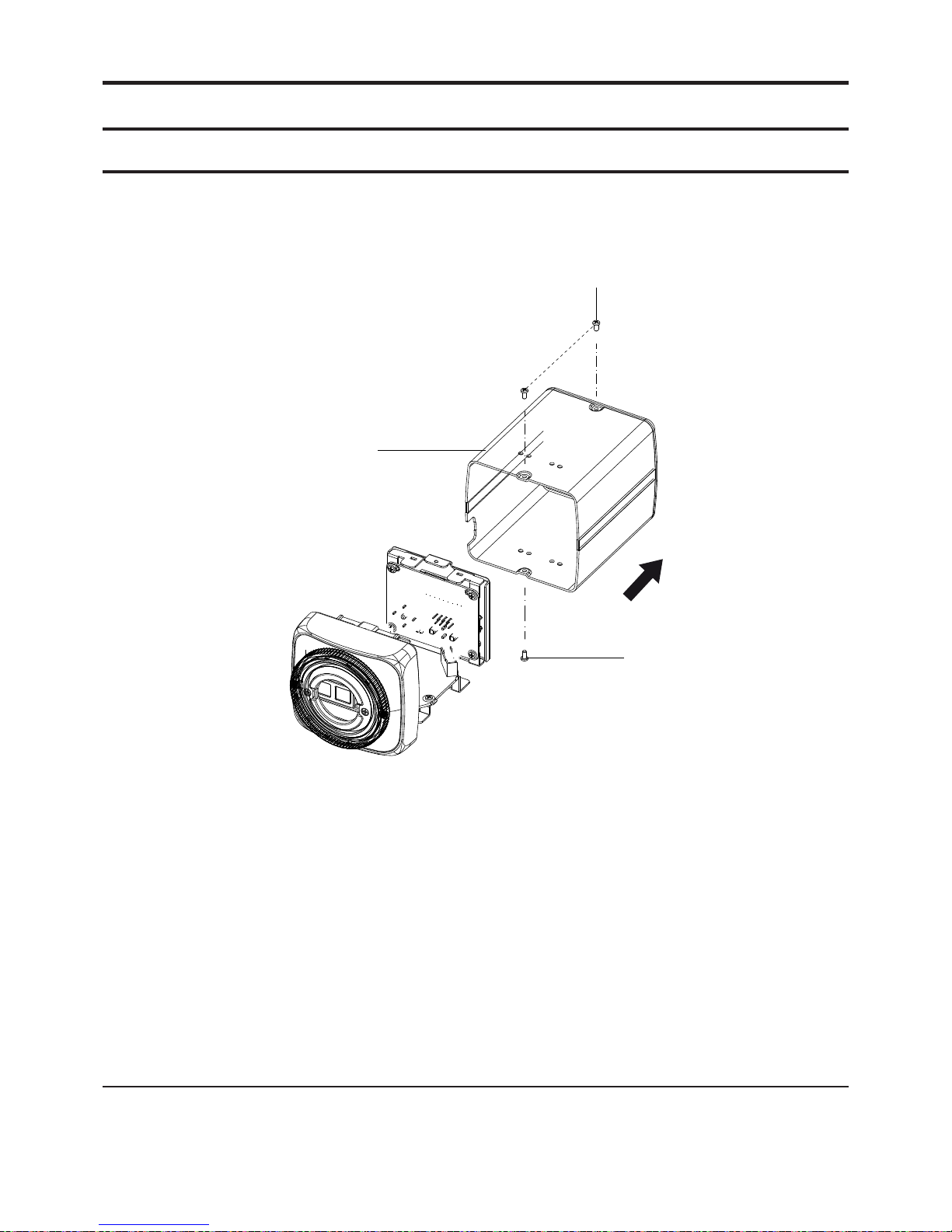
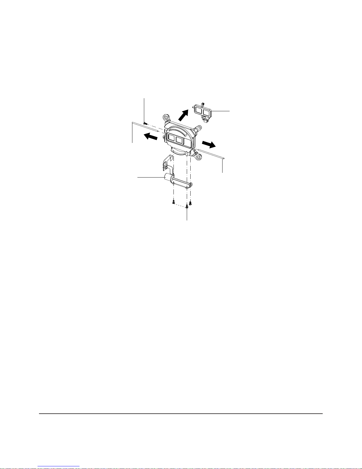
3-1-2 Ass'y Rear & Ass'y Front Removal
1) Remove 2 screws q.
2) Remove Ass'y Rear w.
3) Remove 2 screws e.
4) Remove Cover Guide r.
5) Remove Guide Slider t.
Fig 3-2 Ass'y Rear & Ass'y Front Removal
q 2 SCREWS
(2X4 B)
e 2 SCREWS
(2X4 B)
w ASS'Y REAR
t GUIDE SLIDER
r COVER GUIDE
Samsung Electronics 3-3
Disassembly and Reassembly
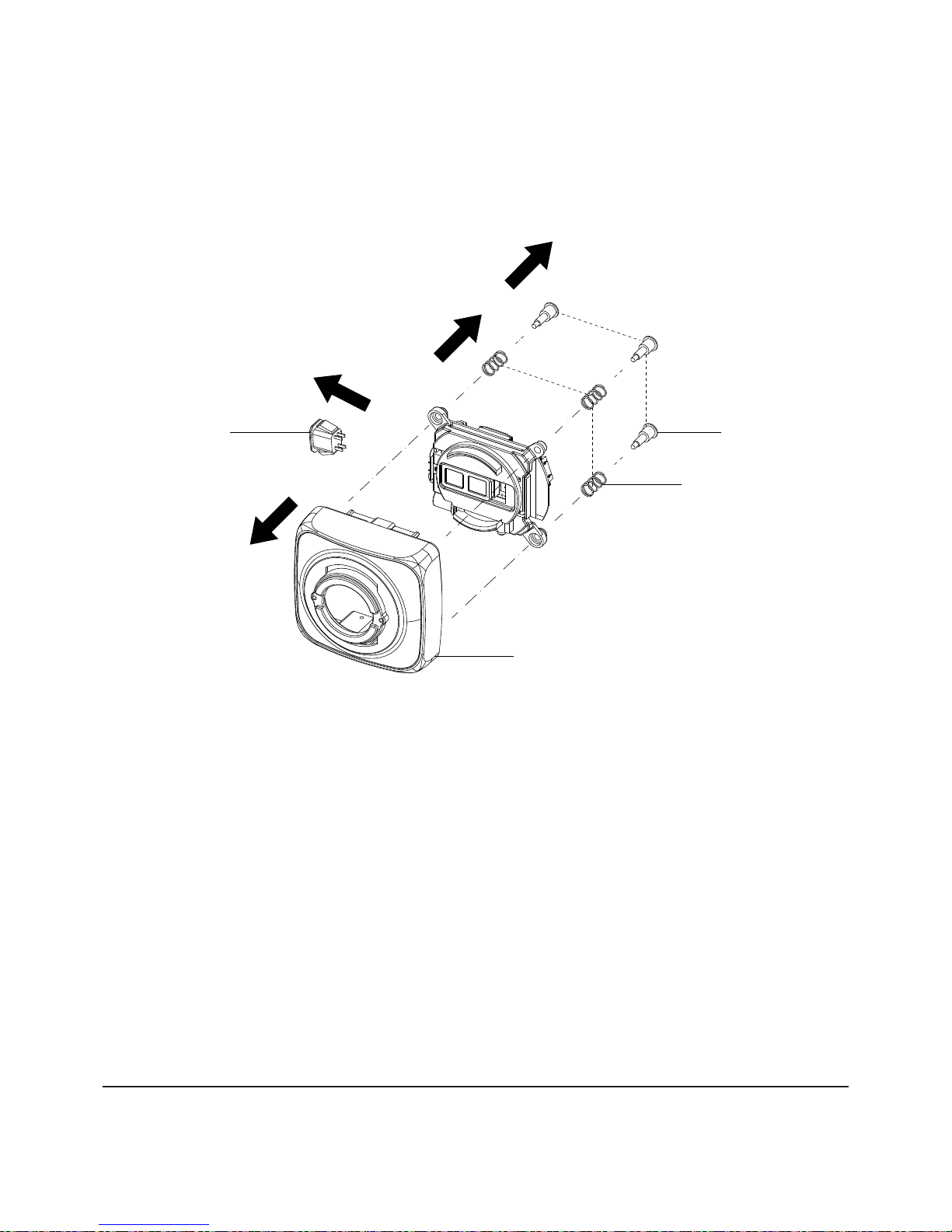
3-1-3 Front Case Removal
1) Remove Harness AI q.
2) Remove 2 Guide Pins w.
3) Remove 2 Spring Pins e.
4) Remove Front Case r.
q
HARNESS AI
Fig 3-3 Front Case Removal
r FRONT CASE
e 2 SPRING PINS
w 2 GUIDE PINS
Disassembly and Reassembly
3-4 Samsung Electronics
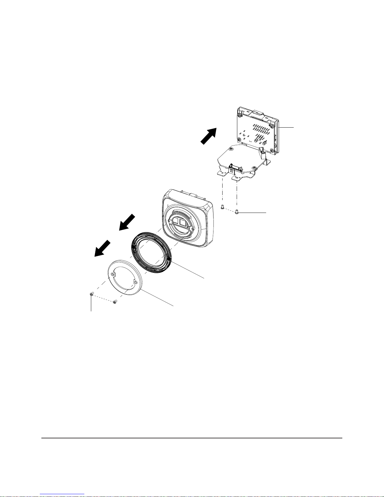
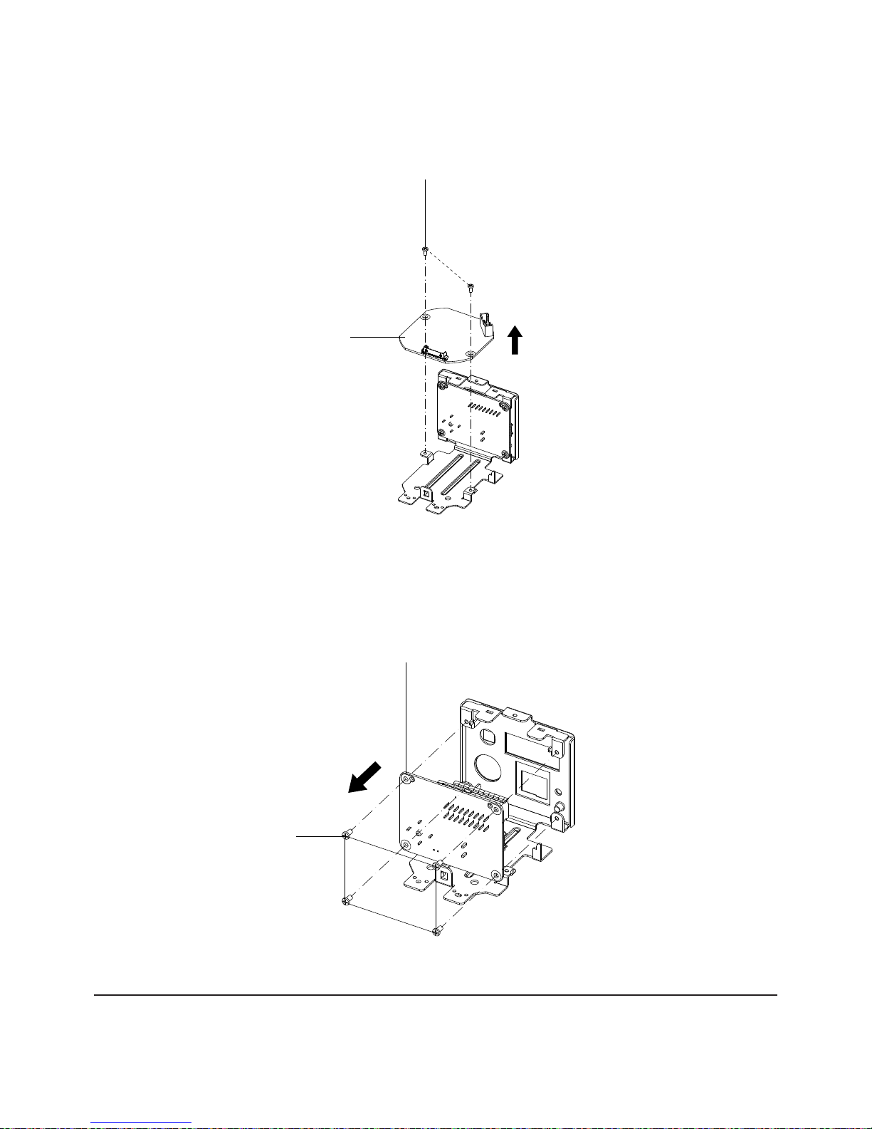
3-1-4 Ass'y CCD PCB Removal
1) Remove 2 Screws q.
2) Remove Ass'y CCD PCB w.
3) Remove 1 Screw e.
4) Remove Cover Filter r.
e
1 SCREW
(7X4 B)
q 2 SCREWS
(7X4 B)
r COVER FILTER
w ASS'Y CCD PCB
Fig 3-4 Ass'y CCD PCB Removal
Samsung Electronics 3-5
Disassembly and Reassembly
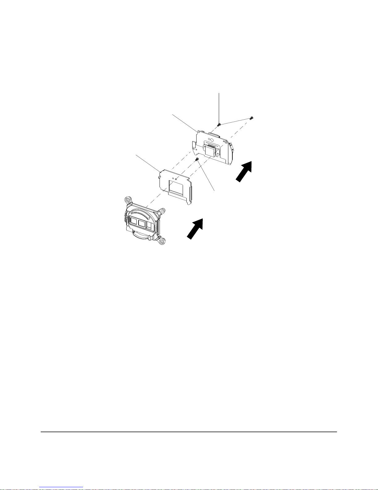
3-1-5 Ass'y Motor & Ass'y OLPF Removal
1) Remove 4 screws q,w.
2) Remove Ass'y Motor e.
3) Remove 2 Guide Filters r,t.
4) Remove Ass'y OLPF y.
w
3 SCREWS
(7X4 B)
q 1 SCREW
(7X4 B)
t 1 GUIDE FILTER
r 1 GUIDE FILTER
Fig 3-5 Ass'y Motor & Ass'y OLPF Removal
e ASS'Y MOTOR
y ASS'T OLPF
Disassembly and Reassembly
3-6 Samsung Electronics
3-1-6 ACDC PCB Removal
1) Remove 2 Screws q.
2) Remove ACDC PCB w.
q
2 SCREWS
(2X4 B)
w ACDC PCB
Fig 3-6 ACDC PCB Removal
3-1-7 Ass'y Rear PCB Removal
1) Remove 4 Screws q.
2) Remove Ass'y PCB w.
Fig 3-7 Ass'y Rear PCB Removal
q 2 SCREWS
(2X4 B)
w ASS'Y REAR PCB

4. Trouble Shooting
Samsung Electronics 4-1
4-1 Trouble Shooting -------------------------------------------------------------------------------- 4-2
4-2 Alignment & Adjustment -------------------------------------------------------------------- 4-9
4-2 Software Update -------------------------------------------------------------------------------4-13
 Loading...