


SCC-B2333(P)
SCC-B2033P
DIGITAL COLOR CAMERA
user manual
imagine the possibilities
Thank you for purchasing this Samsung product.
To receive more complete service,
please register your product at
www.samsungsecurity.com
ENG RUS
ENG
POL
CZE
TUR
Safety information
CAUTION
RISK OF ELECTRIC SHOCK.
DO NOT OPEN
CAUTION: TO REDUCE THE RISK OF ELECTRIC SHOCK, DO NOT REMOVE REAR COVER. NO USER SERVICEABLE PARTS
INSIDE. REFER TO QUALIFIED SERVICE PERSONNEL..
This symbol indicates high voltage is present inside. It is dangerous to make any kind of
contact with any inside part of this product.
This symbol alerts you that important literature concerning operation and maintenance
has been included with this product.
WARNING
To prevent damage which may result in fi re or electric shock hazard, do not expose this appliance
•
to rain or moisture.
WARNING
1.
Be sure to use only the standard adapter that is specifi ed in the specifi cation sheet. Using any
other adapter could cause fi re, electrical shock, or damage to the product
Incorrectly connecting the power supply or replacing battery may cause explosion, fi re, electric
2.
shock, or damage to the product.
Do not connect multiple cameras to a single adapter. Exceeding the capacity may cause
3.
abnormal heat generation or fi re.
Securely plug the power cord into the power receptacle. Insecure connection may cause fi re.
4.
When installing the camera, fasten it securely and fi rmly. A falling camera may cause personal
5.
injury.
Do not place conductive objects (e.g. screwdrivers, coins, metal things, etc.) or containers fi lled
6.
with water on top of the camera. Doing so may cause personal injury due to fi re, electric shock,
or falling objects.
Do not install the unit in humid, dusty, or sooty locations. Doing so may cause fi re or electric
7.
shock.
If any unusual smells or smoke come from the unit, stop using the product. In such case,
8.
immediately disconnect the power source and contact the service center. Continued use in such
a condition may cause fi re or electric shock.
If this product fails to operate normally, contact the nearest service center. Never disassemble
9.
or modify this product in any way. (SAMSUNG is not liable for problems caused by unauthorized
modifi cations or attempted repair.)
2 – DIGITAL COLOR CAMERA

Safety information
10.
When cleaning, do not spray water directly onto parts of the product. Doing so may cause fi re or
electric shock.
CAUTION
Do not drop objects on the product or apply strong shock to it. Keep away from a location
1.
subject to excessive vibrationor magnetic interference.
Do not install in a location subject to high temperature (over 50°C), low temperature (below -
2.
10°C), or high humidity. Doing so may cause fi re or electric shock.
If you want to relocate the already installed product, be sure to turn off the power and then move
3.
or reinstall it.
Remove the power plug from the outlet when then there is a lightning. Neglecting to do so may
4.
cause fi re or damage to the product.
Keep out of direct sunlight and heat radiation sources. It may cause fi re.
5.
Install it in a place with good ventilation.
6.
Avoid aiming the camera directly towards extremely bright objects such as sun, as this may
7.
damage the CCD image sensor.
Apparatus shall not be exposed to dripping or splashing and no objects fi lled with liquids, such as
8.
vases, shall be placed on the apparatus.
The Mains plug is used as a disconnect device and shall stay readily operable at any time.
9.
ENG
English – 3

Important Safety Instructions
Read these instructions.
1.
Keep these instructions.
2.
Heed all warnings.
3.
Follow all instructions.
4.
Do not use this apparatus near water.
5.
Clean only with dry cloth.
6.
Do not block any ventilation openings. Install in accordance with the manufacturer’s instructions.
7.
Do not install near any heat sources such as radiators, heat registers, or other apparatus (including
8.
amplifi ers) that produce heat.
Do not defeat the safety purpose of the polarized or grounding-type plug. A polarized plug has two blades
9.
with one wider than the other. A grounding type plug has two blades and a third grounding prong. The wide
blade or the third prong is provided for your safety. If the provided plug does not fi t into your outlet, consult
an electrician for replacement of the obsolete outlet.
Protect the power cord from being walked on or pinched particularly at plugs,
10.
convenience receptacles, and the point where they exit from the apparatus.
Only use attachments/accessories specifi ed by the manufacturer.
11.
Use only with cart, stand, tripod, bracket, or table specifi ed by the manufacturer, or
12.
sold with the apparatus.
Unplug this apparatus when a card is used. Use caution when moving the cart/
13.
apparatus combination to avoid injury from tip-over.
Refer all servicing to qualifi ed service personnel. Servicing is required when the apparatus has been
14.
damaged in any way, such as powersupply cord or plug is damaged, liquid has been spilled or objects have
fallen into the apparatus, the apparatus has been exposed to rain or moisture, does not operate normally, or
has been dropped.
4 – DIGITAL COLOR CAMERA

Contents
Introduction
Features 6
PRODUCT & ACCESSORIES 7
Part Names and Functions 8
Installation
Connecting the Auto Iris Lens Connector 11
Mounting the lens 11
Connecting cables and checking operation 12
How to use OSD Menu
Using Icons in the Menu 13
Main Menu 13
Profi le 14
Camera Setup 16
Intelligence 22
Privacy Zone Setup
Other Set 25
Communication 26
System Information 26
Language 26
Specifi cations
Specifi cations 28
24
ENG
English – 5

Introduction
FEATURES
High Resolution
❖
This camera has realized high resolution of 600 lines using the top-notch full digital image processing and
•
special algorithm technologies.
Intelligent Motion Detection & Tracking
❖
•
This is an intelligent function that automatically detects a motion of an object. You can set a virtual fence so it
sounds an alert if an object passes / enters /exits the virtual fence or virtual area.
❖
XDR (eXtended Dynamic Range)
Actively controls the gamma compensation in the way it operates the ambient luminance contrast in a
•
certain pixel unit to determine the optimal visibility.
DAY/NIGHT
❖
•
This function can make the IR Cut fi ltering function inactive under the illumination below the normal value.
❖
High Sensitivity
It implements images of high sensitivity using the up-to-date SONY Super-HAD IT CCD..
•
Low Illumination
❖
It uses the digital signal technologies such as low illumination and Day/Night functions that make your camera
•
identify objects even in the worst environment.
Superior Backlight Adjustment
❖
•
When an object has a bright illumination or sunlight behind it, this camera automatically improves the
shaded object picture quality.
❖
Digital Power Synchronization
The full digital Line Lock function directly adjusts the vertical camera synchronization to enhance the
•
operationability and reliability of this camera.
Output Signal Setting
❖
You can set the following Video output signals: Image reversion (Horizontal, Vertical, or both), Privacy,
•
Horizontal/Vertical profi ling, and digital zooming.
OSD(On Screen Display) Menu
❖
•
OSD menu is provided to display the status of camera and to confi gure the functions interactively.
Coaxial Cable Communication
❖
This is a remote control function that overlaps the coaxial cable (for a transfer of the video signal) with the
•
control signal. In installation or repair, this helps you control the communication controller (optional) without
additional cabling.
6 – DIGITAL COLOR CAMERA

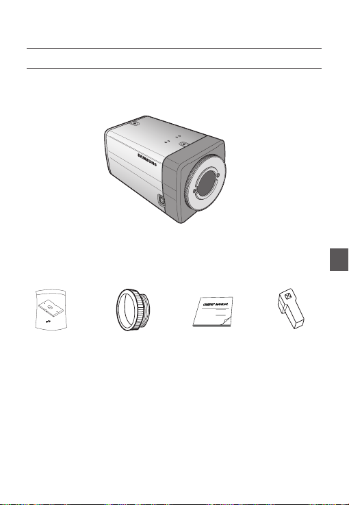
PRODUCT & ACCESSORIES
Product & Accessories❖
Main Product
•
Accessories
•
Camera Holder(Mount)
C Mount Adapter
Camera
Introduction
User’s Manual
Lens Connector
ENG
Auto Iris
English – 7

Introduction
PART NAMES AND FUNCTIONS
Side View❖
Mount Adapter
Fixing Grooves
Auto Iris Lens
Connector
Auto Iris Lens
Control Cable
Auto Iris Lens Connector
•
This groove is used for screwing the mount adapter, a part of the bracket where the camera will be installed.
Auto Iris Lens Control Cable
•
This cable transmits the power and signals from the camera for controlling the Auto Iris Lens.
Mount Adapter Fixing Grooves
•
These grooves are used when fi xing screws of the mount adapter connected to the bracket when installing
the camera on it.
Note :
When the camera lens becomes dirty, softly clean it with a lens tissue or a cloth soaked in pure ethanol.
–
8 – DIGITAL COLOR CAMERA
Camera Lens
Introduction
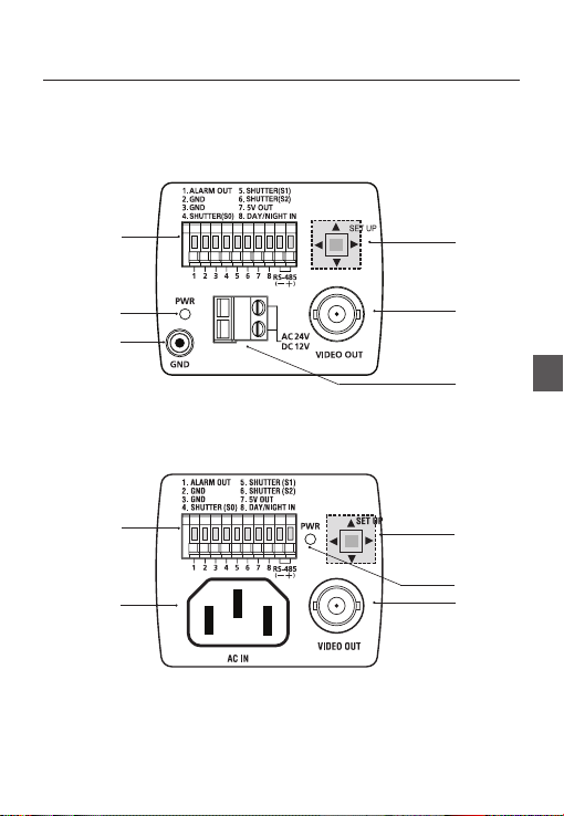
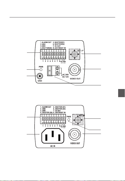
Rear Panel❖
<AC24/DC12V (B2333(P))>
n
p
r
<AC220V~240V(SCC-B2033P)>
n
s
o
q
ENG
s
o
p
q
English – 9
Introduction
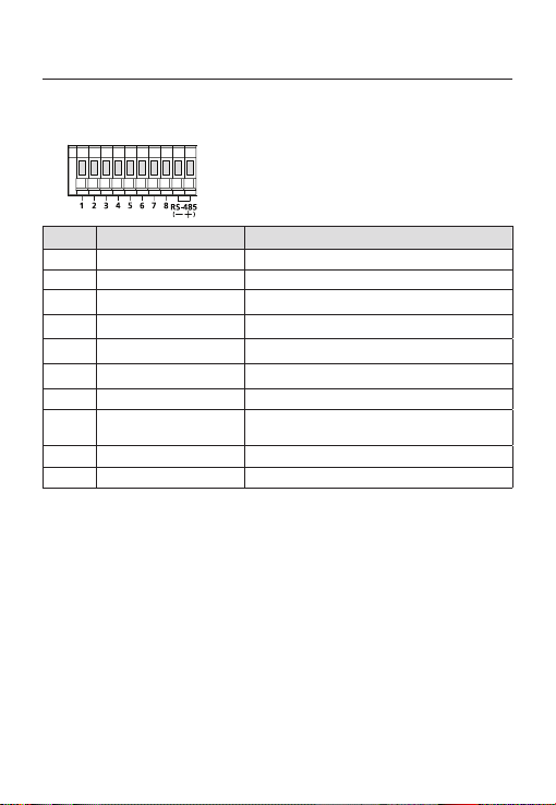
n Input/Output Connector
This connector has input and output ports for RS-485 control signals, DAY/NIGHT switching, and alarm
output signals.
No. Function Description
1 ALARM OUT
2 GND Grounding Port.
3 GND Grounding Port.
4 SHUTTER (S0)
5 SHUTTER (S1)
6 SHUTTER (S2)
7 5V OUT
8
9 RS-485 DATA-
10 RS-485 DATA+
o SETUP Switch
This switch is used to set the function or property. When this switch is pressed for at least 2 seconds, the
MAIN MENU appears.
ef
(Left/Right)
cd
(Up/Down) :
: When you press this switch in the menu, the selected function is confi rmed. To enter a submenu, press
this button.
p Power Display LED
When the power is normally connected, the red LED lights.
q Video OUT Port
This is connected to the Video Input Port of the monitor and it outputs the Video signals.
r GND
This is a grounding port.
s Power Connection Port
This is connected to the Power cable.
DAY/NIGHT IN
: By pressing this switch left or right, you can move left or right on the menu or change the
displayed value.
By pressing this switch up or down, you can move up or down on the menu.
10 – DIGITAL COLOR CAMERA
Alarm out port for motion detection. (Open collector type)
This is a port for selecting an external high speed shutter mode.
If connected in LOW (0V), it will become ON inside.
This is a port for selecting an external high speed shutter mode.
If connected in LOW (0V), it will become ON inside.
This is a port for selecting an external high speed shutter mode.
If connected in LOW (0V), it will become ON inside.
Power supply port for RS-485 JIG. Use within typical DC +5V 100mA
This is a port for DAY&NIGHT conversion.
High(DC +3V~+5V) : DAY(COLOR) Mode,
Low(0V) : NIGHT(BW) Mode
This is a port for connection to RS-485 DATA- signal line.
This is a port for connection to RS-485 DATA+ signal line.

CONNECTING THE AUTO IRIS LENS
CONNECTOR
Installation
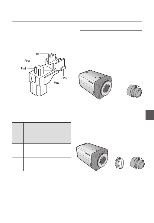
MOUNTING THE LENS
When using the CS lens
Mount the CS lens by rotating it clockwise as shown
in the picture:
CS lens
CS 렌즈
Connect each uncovered shutter control cables to
the Auto Iris Lens Connector as the following
Pin
DC Control
No.
1 Damp(-) Power (+12V)
2 Damp(+) Not applicable
3 Drive(+) Video Signal
4 Drive(-) Ground
Note :
You can switch a control type of the lens in the menu.
–
Type
Video Control Type
When using the C lens
After mounting the C-mount adapter by rotating it
clockwise, turn the C lens clockwise until it is fi xed as
shown in the picture.
C 렌즈
C lens
English – 11
ENG

Installation
CONNECTING CABLES AND
CHECKING OPERATION
①
Connect one end of the BNC cable to the
VIDEO OUT Port on the rear of the camera.
② Connect another end of the BNC cable to the
VIDEO IN Port on the monitor.
Video In Terminal of Monitor Rear
Surface
BNC cable
1
.
A
L
A
R
2
.
A
G
M
N
O
D
3
U
.
T
G
N
5
.
D
S
4
.
H
S
U
H
6
T
U
.
T
S
T
E
T
H
R
E
U
(
S
R
7
T
1
(
.
T
S
)
5
E
O
V
R
)
(
O
S
8
U
2
.
)
T
D
A
Y
/
N
I
G
H
T
I
N
1
2
3
4
5
6
7
8
③
Finally connect the power adapter to the
camera. You can connect 2 lines of the power
adapter to the camera using the Slot Head
screwdriver as shown in the picture.
(GND: cable with the white stripe line)
1
.
A
L
A
R
2
.
A
G
M
N
O
D
3
U
.
T
G
N
5
.
D
S
4
.
H
S
U
H
6
T
U
.
T
S
T
E
T
H
R
E
U
(S
R
7
T
1
(
.
T
S
)
5
E
O
V
R
)
(S
O
8
U
2
.
)
T
D
A
Y
/
N
I
G
H
T
I
N
1 2
3 4
5 6
7
8
Video Out Terminal
12 – DIGITAL COLOR CAMERA
Note :
Connect any power source of AC 24V and DC 12V
–
irrespective of polarity.

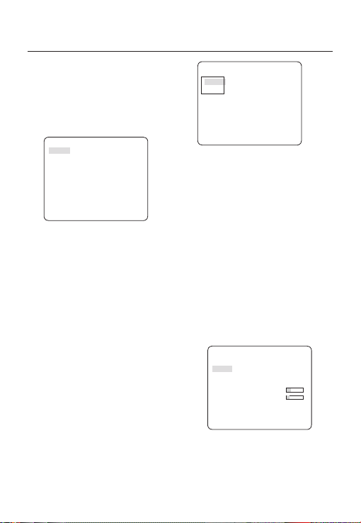
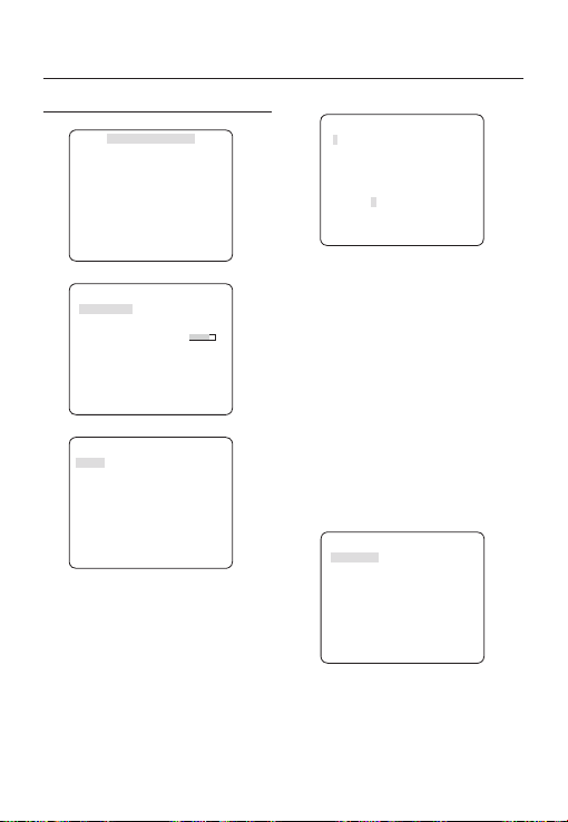
How to use OSD Menu
USING ICONS IN THE MENU
(EXIT)
•
Exits the menu setting.
Before you exits the menu setting, select SAVE to
save your settings, or select QUIT to cancel.
(RET)
•
Returns to the previous menu.
(HOME)
•
Returns to the main menu.
(SAVE)
•
Used to save your settings of MASK AREA,
PRIVACY ZONE and more.
Once you save your settings, they will remain
even if you select QUIT in the menu.
(DEL)
•
Used to deletes your settings of MASK AREA,
PRIVACY ZONE and more.
Once you delete your settings, they will not be
restored even if you select QUIT in the menu.
MAIN MENU
ÃÃMAIN MENUÃÃ
PROFILE
CAMERA SET
INTELLIGENCE
PRIVACY ZONE
OTHER SET
COMMUNICATION
SYSTEM INFO
LANGUAGE
PROFILE
•
You can set a mode according to the camera
installation conditions.
CAMERA SET
•
Confi gure Camera related functions and data.
INTELLIGENCE
•
You can confi gure the settings of motion
detection, tracking and more.
PRIVACY ZONE
•
You can confi gure the privacy related settings.
OTHER SET
•
You can confi gure for Factory Defaults, and more.
COMMUNICATION
•
Confi gures the settings regarding the RS-485
communication.
SYSTEM INFO.
•
Displays the system information including the
camera version and communication settings.
LANGUAGE
•
Select a preferred one from the supported
languages.
ENG
English – 13
How to use OSD Menu
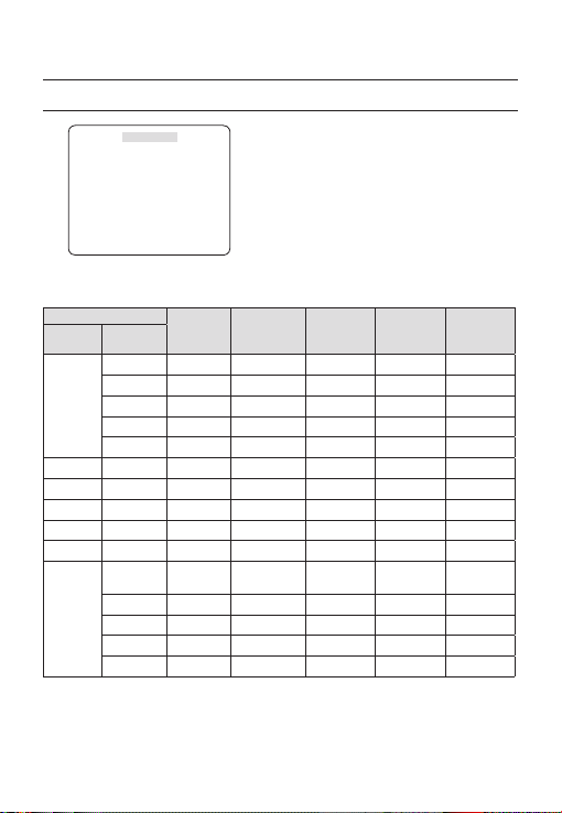
PROFILE
e
PROFILE
f
STANDARD
Ã
ITS
BACKLIGHT
DAY/NIGHT
GAMING
CUSTOM
In the PROFILE menu, you can confi gure the following camera settings at once.
CAMERA SET Menu
Previous
Menu
IRIS ALC ALC ALC ALC ALC
MOTION (F.FAST)--- (F.FAST)--- NORM (F.FAST)--- SLOW
DNR MID MID MID MID MID
SHUTTER OFF AUTO1/250 OFF OFF OFF
SENS-UP AUTOx4 AUTOx2 AUTOx4 AUTOx4 AUTOx4
XDR MID MID MID MID MID
DAY/
NIGHT
STANDARD ITS BACKLIGHT DAY/NIGHT GAMING
Sub-menus
ALC -- ---
LENS DC DC DC DC DC
LEVEL 0 0 0 0 0
BACKLIGHT OFF OFF BLC OFF OFF
AUTO AUTO DAY AUTO DAY
NIGHT - - - - -
BURST OFF ON OFF OFF OFF
EXT -- ---
BURST OFF ON OFF OFF OFF
14 – DIGITAL COLOR CAMERA

How to use OSD Menu
CAMERA SET Menu
Previous
Menu
WHITE
BAL
DETAIL 2 2 2 2 2
ITS
❖
STANDARD ITS BACKLIGHT DAY/NIGHT GAMING
Sub-menus
DAY DAY/NIGHT DAY DAY/NIGHT DAY
DAY -- ---
MODE ATW2 ATW1 ATW1 ATW1 ATW1
RED00 000
BLUE 0 0 0 0 0
NIGHT - - - - -
User setting
BRIGHTNESS
allowed
MODE OFF ATW2 OFF ATW2 OFF
User setting
RED
allowed
User setting
BLUE
allowed
User setting
MID
allowed
User setting
0
allowed
User setting
0
allowed
MID
0
0
User setting
allowed
User setting
allowed
User setting
allowed
ENG
It will be set automatically so you can easily check the traffi c conditions.
BACKLIGHT
❖
It will be set automatically so you can distinguish the object from the background in a severe backlighting scene.
DAY/NIGHT
❖
It will be set automatically so it optimizes to the day or night conditions, respectively.
GAMING
❖
It will be set automatically to help you take a picture in a regular indoor lighting condition.
English – 15

How to use OSD Menu
CAMERA ID [OFF, ON]
CAMERA SETUP
eCAMERA SETf
CAMERA ID OFF
IRIS ALC
MOTION (F.FAST)--DNR MID
SHUTTER OFF
SENS-UP AUTO X4
FLICKERLESS (OFF)--XDR MID
DAY/NIGHT AUTO
WHITE BAL
DIGITAL ZOOM
DETAIL [2]
V-SYNC INT
AGC COLOR SUP
REVERSE OFF
POSI/NEGA +
PIP OFF
DIS OFF
Setup the general functions of zoom camera module.
Use the
cdef
d
c
OFF
LOW
d
c
switch to select a menu item.
❖
CAMERA ID
ABCDEFGHIJKLMNOPQRSTUVWXYZ0
123456789 :?-+*()/
SP
ffee
SP LOCATION
CAMERA-1..................
...........................
The CAMERA ID menu is used for you to assign
a unique name to a camera. If you press the
SETUP switch with the CAMERA ID menu
selected, you will see the appropriate screen.
You can enter up to 54 alphanumeric or
special characters for the CAMERA ID. Select
LOCATION and press the SETUP switch to
move the display position of the CAMERA ID.
❖
IRIS [ALC, ELC]
The IRIS menu is used if you want to adjust the
intensity of radiation incoming to the camera.
•
ALC (Automatic Light Control)
① If you press the SETUP switch with an ALC-
based sub menu selected, you will see the
appropriate screen.
ALC
LENS DC
LEVEL [00]----I---BACKLIGHT OFF
The LENS menu is used if you select a type of
the AI lens.
For normal operation, you must select DC for a
DC-type lens, and select VIDEO for a VIDEOtype lens.
16 – DIGITAL COLOR CAMERA

How to use OSD Menu
The LEVEL menu is used to adjust the
overall brightness, where “+” will increase the
brightness and “–” will decrease it.
② If you set the BACKLIGHT option to BLC,
you will see a menu where you can set the
BLC area.
you can set the desired BLC zone by defi ning
the size and location.
ALC
LENS DC
LEVEL [00]----I---BACKLIGHT BLC
AREA USER
<SIZE>
<LOCATION>
If you use an ordinary camera in a scene
with an intensive backlight, the object will be
displayed dark on the monitor affected by the
backlight. To solve this problem, you can use
the BLC(Back Light Compensation) function
to improve the sharpness of the image in
such a high contrast scene.
ELC (Electronic Light Control)
•
If you press the SETUP switch when the ELC
①
submenu is selected, the corresponding screen
appears. You can make the ELC (Electronic Light
Control) function active or not.
ELC
LEVEL [00]----I---BACKLIGHT OFF
② In similar to ALC setting, you can specify the
BLC area.
ELC
LEVEL [00]----I---BACKLIGHT BLC
AREA USER
<SIZE>
<LOCATION>
AGC
❖
[OFF, VERY LOW, LOW, MID, HIGH, VERY
HIGH, USER, FIX]
The AGC (Auto Gain Control) menu is used to
set the AGC level of the camera. When the AGC
is active, the camera automatically increases the
sensitivity by amplifying the Video signal when
the strength of the signal falls below the normal
value.
If OFF or FIX mode is selected in the SENS-UP
menu, you can specify the AGC level.
If you press the SETUP switch with a USER
sub menu selected, you will see the appropriate
screen.
AGC USER
LEVEL [16]
In USER mode, you can break down the level in
16 steps from VERY LOW to VERY HIGH to your
preference.
ENG
English – 17

How to use OSD Menu
SHUTTER
AGC FIX
LEVEL [01]
If you press the SETUP switch with a FIX sub
menu selected, you will see the appropriate screen.
As a fi xed value of the AGC gain is used in FIX
mode, you can select one of the 16 detailed levels
from VERY LOW to VERY HIGH before fi xing it.
Note :
If the DAY/NIGHT menu of the CAMERA SET is set to
–
AUTO, the AGC menu will be deactivated.
If FLICKERLESS is set to ON, the AGC FIX mode will be
–
disabled.
❖
MOTION
Note :
–
DNR
❖
[S.SLOW, SLOW, NORM, FAST, F.FAST]
The MOTION menu is used to adjust the strength
of the AGC level for a control of the camera motion.
This is available only if the SENS-UP menu is set
to AUTO.
You can select one from S.SLOW, SLOW, NORM,
FAST and F.FAST for the AGC level.
If you monitor a fast moving object in a low contrast
scene, select F.FAST while select S.SLOW for a
hardly moving object in the same lighting condition.
If the DAY/NIGHT menu of the CAMERA SET is set to
AUTO, the MOTION menu will be deactivated.
[OFF,LOW,MID,HIGH, USER(1~16)]
You can confi gure the DNR (Digital Noise
Reduction) related settings.
Reduces the noise on the screen.
This is especially useful for a severely distorted screen.
You can set the level if you set DNR to USER.
❖
[OFF, AUTO 1/100(PAL:1/120), AUTO 1/250,
AUTO 1/500, AUTO 1/1000, AUTO 1/2000, AUTO
1/4000, AUTO 1/10K , 1/100(PAL:1/120), 1/250,
1/500, 1/1000, 1/2000, 1/4000, 1/10K , EXT]
The SHUTTER menu is used to set the fi xed
high-speed electronic shutter, auto high speed
electronic shutter and external high speed
electronic shutter(EXT).
You can select one of 7 options from 1/100(PAL:1/120)
to 1/10K for the fi xed high speed electronic shutter,
which is mostly used for imaging a fast moving object.
The auto high speed electronic shutter operates
as the fi xed high speed shutter in a high contrast
scene but automatically focuses the target if the
iris opens fully in a low contrast scene like in ELC
mode. When it gets brighter back, the mode will
switch to the fi xed high speed electronic shutter
mode.
However, the auto high speed shutter operates
properly only in a camera featuring a DC or VIDEO
lens.
In external high speed electronic shutter (EXT)
mode, you can select one of 8 modes from OFF
through 1/100(PAL:1/120) to 1/10K for the high
speed electronic shutter. It works as the high
speed electronic shutter. You can select an
option using SHUTTER(S0), SHUTTER(S1) and
SHUTTER(S2) on the rear.
Connect each of the terminals to GND.
See the below table for the operation.
SHUTTER(S0) SHUTTER(S1) SHUTTER(S2)
OFF
(NTSC: 1/60,
OFF OFF OFF
PAL:1/50)
1/100
(PAL:1/120)
ON OFF OFF
1/250 OFF ON OFF
1/500 ON ON OFF
1/1000 OFF OFF ON
18 – DIGITAL COLOR CAMERA

How to use OSD Menu
1/2000 ON OFF ON
1/4000 OFF ON ON
1/10K ON ON ON
Note :
If IRIS mode is set to ELC, the SHUTTER menu will be
–
deactivated as you adjust the brightness using the
electronic shutter.
If the SENS-UP function is set to AUTO, only items of
–
OFF and AUTO are available in the SHUTTER menu.
If the SENS-UP mode is set to FIX, the SHUTTER menu
–
will be deactivated.
If the FLICKERLESS function is set to ON, the SHUTTER menu
–
will be deactivated.
SENS-UP
❖
[OFF, AUTO X2, AUTO X4, AUTO X6, AUTO
X8, AUTO X12, AUTO X16, AUTO X24, AUTO
X32, AUTO X48, AUTO X64, AUTO X96, AUTO
X128, AUTO X256, AUTO X512, FIX X2, FIX
X4, FIX X6, FIX X8, FIX X12, FIX X16, FIX X24,
FIX X32, FIX X48, FIX X64, FIX X96, FIX X128,
FIX X256, FIX X512]
Automatically detects the ambient level of
darkness in the dark or low contrast scene to
extend the accumulated time, keeping the image
bright and sharp; It can be also used as FIX
mode.
Note :
If the SHUTTER option is set to fi xed electronic shutter or
–
EXT mode, the SENS-UP menu will be deactivated.
If FLICKERLESS is set to ON, the FIX mode of the SENS-
–
UP menu will be disabled.
If the IRIS menu is set to ELC, the electronic shutter will
–
control the brightness so the SENS-UP function can not
be set to FIX mode, but to OFF or AUTO mode.
If the SHUTTER menu is set to AUTO, the SENS-UP
–
menu can be set to either OFF or AUTO mode.
FLICKERLESS [OFF, ON]
❖
If set to ON, the shutter speed will be fi xed to
1/100(PAL:1/120) second. This will prevent possible screen
distortion due to a mismatch between the vertical sync
frequency and the blinking frequency of the lighting.
Note :
–
If the IRIS function is set to ELC, the Flickerless menu will
be deactivated. If the SHUTTER menu is set to AUTO, FIX
or EXT mode, the Flickerless menu will be deactivated.
–
If the SENS-UP function is set to FIX mode, the Flickerless
menu will be deactivated.
–
If AGC is set to FIX mode, the FLICKERLESS function will
be disabled.
XDR (eXtended Dynamic Range)
❖
[OFF, LOW, MID, HIGH]
Actively controls the gamma compensation in the
way it operates the ambient luminance contrast
in a certain pixel unit to determine the optimal
visibility.
Select one from OFF, LOW, MID and HIGH.
Closing to HIGH will increase the compensation
level.
DAY/NIGHT
❖
DAY
•
If set to DAY, it will be fi xed to DAY mode
regardless of the ambient conditions.
NIGHT
•
If set to NIGHT, it will be fi xed to Black-and-White
mode regardless of the ambient conditions.
If you press the SETUP switch with a NIGHT sub
menu selected, you will see a menu where you can
set Burst to OFF/ON.
If BURST is set to ON, the Burst signal will output
together with the black-and-white composite video
signal. If BURST is set to OFF, the Burst signal does
not output.
You can set the BURST option to OFF/ON, or
select to output the Burst signal in NIGHT mode.
[DAY,NIGHT,AUTO,EXT]
ENG
English – 19
How to use OSD Menu
AUTO
•
The camera will automatically switch between
DAY and NIGHT mode, according to the lighting
condition.
If you press the SETUP switch with an AUTObased sub menu selected, you will see the
appropriate screen.
AUTO
BURST OFF
DAYÆNIGHT
BRIGHTNESS MID
DWELL TIME 2S
NIGHTÆDAY
BRIGHTNESS MID
DWELL TIME 5S
MASK AREA 1 2
You can set the BURST option to OFF/ON, or
select to output the Burst signal in NIGHT mode.
You can select from LOW, MID and HIGH for
the brightness of DAYÆNIGHT, which is a
brightness level in switching from the color fi lter
to Black-and-White. Closing to LOW from HIGH
will switch the fi lter in a low contrast scene.
The DWELL TIME of DAYÆNIGHT is a time
required to determine the need for switching the
fi l t e r .
You can select from LOW, MID and HIGH for
the brightness of NIGHTÆDAY, which is a
brightness level in switching from the Black-andWhite fi lter to color. Closing to LOW from HIGH
will switch the fi lter in a low contrast scene.
The DWELL TIME of NIGHTÆDAY is a time
required to determine the need for switching the
fi l t e r .
The MASK menu is used to prevent a fi lter
switch error or inability of determining the switch
in existence of a high spot light source at night.
If you press the SETUP switch in item 1 or 2 of
the MASK menu, you will see a menu where you
can specify an area to mask.
MASK AREA
<SIZE>
<LOCATION>
You can specify Mask 1 and 2 simultaneously.
The mask is used only for determining the fi lter
switch and any excessive bright area at night will
be masked.
Note :
If BACKLIGHT is set to BLC, the MASK AREA function will
–
be deactivated.
EXT
•
This enables an auto switch between DAY and
NIGHT mode using the interface with the external
sensor.
WHITE BAL [DAY/NIGHT]
❖
If you want to adjust the color scheme, use the
WHITE BALANCE function.
DAY
•
In DAY mode, you can set the color values of
RED and BLUE. The screen will be displayed in
colors according to your settings.
WHITE BAL
DAY/NIGHT DAY
MODE AWC
RED [00]----I--- BLUE [00]----I--- R-GAIN [0248]
B-GAIN [0247]
Note :
You can set the values of R-GAIN and B-GAIN only in
–
AWC mode.
20 – DIGITAL COLOR CAMERA

How to use OSD Menu
•
NIGHT
Use the NIGHT mode if you want to set the white
balance differently according to the ambient
luminance.
If the NIGHT mode is set to OFF, the white
balance will always operate as set in DAY mode;
if not to OFF, the camera will switch to as set in
DAY/NIGHT mode according to the brightness.
In NIGHT mode, you can set the values of RED,
BLUE and BRIGHTNESS. The screen will be
displayed in colors according to your settings.
WHITE BAL
DAY/NIGHT NIGHT
BRIGHTNESS MID
MODE AWC
RED [00]----I--- BLUE [00]----I--- R-GAIN [0248]
B-GAIN [0247]
Note :
–
You can set the values of R-GAIN and B-GAIN only in
AWC mode.
If AGC is set to OFF or FIX, you can not access the
–
NIGHT menu.
–
For adjusting the white balance, the following
5 modes are provided:
•
ATW1(Auto Tracing White Balance mode
1): The camera can automatically adjust the
color temperature in real time, according to
the ambient conditions. The color temperature
ranges from approx. 2500K to 9300K.
•
ATW2: The color temperature ranges from
approx. 2,000K to 10,000K.
•
AWC ( Auto White Balance Control): If you
press the SETUP switch in the appropriate item
position, Auto White Balance will perform once.
•
3200K : Set color temperature to 3200K
•
5600K : Set color temperature to 5600K
RED : Adjusts the strength of the red color.
–
BLUE : Adjusts the strength of the blue color.
–
R-GAIN/B-GAIN : Enables you to set the current
–
color temperature manually.
BRIGHTNESS : Select a brightness level in
–
switching from setting in DAY mode to setting in
NIGHT mode.
DIGITAL ZOOM [ON/OFF]
❖
You can set the digital zoom factor and position.
If you press the SETUP switch with the DIGITAL
ZOOM function set to ON, you will see the
appropriate screen.
When the zoom factor and position are defi ned,
the digital zoom function will operate.
DIGITAL ZOOM
RATIO [X1.0]
< LOCATION >
-
LOCATION : If you press the SETUP switch in the
condition where the image is enlarged as much as the
ratio setting, you can watch an invisible area of the
effective screen as well using the
Note :
If the digital zoom factor is set to larger than 1x, the FENCE
–
function will be deactivated.
The DIGITAL ZOOM function enlarges the pixel itself, which can
cause deterioration of the quality.
DETAIL [0~3]
❖
cdef
switch.
Controls the horizontal or vertical distinction.
ENG
English – 21

How to use OSD Menu
V-SYNC [INT, LINE]
❖
Select the vertical sync mode for INT or LINE.
If you select INT, the camera will use the internal
synchronization.
If selecting LINE, the camera will use the external
power source frequency for the synchronization.
You can adjust the LL-PHASE.
Note :
Use of DC 12V will fi x V-SYNC to INT, which can not be
–
changed.
AGC COLOR SUP [LOW , MID, HIGH]
❖
Adjust the color scheme according to the AGC
value.
REVERSE [OFF, H, V, H/V]
❖
Mirrors video signals horizontally, vertically, or
both.
POSI/NEGA [+, -]
❖
Output as it is or mirror the video brightness
signal.
PIP [OFF, ON]
❖
Displays a sub image together with the main
image on the same screen using the Picture In
Picture function.
Note :
If more than one privacy zone is set and the PRIVACY
–
SET is set to ON, the PIP function will be deactivated.
If the INTELLIGENCE function is set to FENCE mode, the
–
PIP menu will be deactivated.
DIS [OFF, ON]
❖
Digital Image Stabilization will set the anti-shake
compensation.
Note :
If you set DIS to ON, the compensation area will be
–
enlarged as set in the digital zoom factor.
If you set the digital zoom factor to greater than the
enlarged zoom factor for the compensation, the DIS
function will be deactivated.
INTELLIGENCE
eINTELLIGENCEf
MOTION OFF
ADVANCED OFF
MASK AREA
DISPLAY ON
SENSITIVITY [4]
RESOLUTION [5]
ALARM OUT
You can set the motion detection and tracking in the
INTELLIGENCE menu.
MOTION
❖
•
TRACKING
Detects and tracks a moving object.
•
DETECTION
Detects a moving object.
Note :
If it is set to DETECTION, you can not set such functions as
–
FIXED/MOVED and FENCE in the ADVANCED menu.
ADVANCED
❖
Detects a motion of an object and displays an
image of any moving object before tracking the
moving route.
FENCE
•
This is to detect if a moving object passes
through the specifi ed LINE or AREA.
In a condition where a moving object is detected
in an analysis of the previous and current frames
whose movement overlaps a certain area, the
system displays “PASS” if the object’s center line
passes through the line while it displays “ENTER”
or “EXIT” if the center point passes through the
area.
[OFF,TRACKING,DETECTION]
[OFF, FIXED/MOVED, FENCE]
1 2 3 4
22 – DIGITAL COLOR CAMERA

How to use OSD Menu
FENCE
LINE OFF
AREA OFF
You can set the position and detection direction of the
LINE, and the size and position of the AREA.
- How to set the line
LINE
PIXEL LEVEL [4]
<POINT>
DIRECTION §¨
① If you press the SETUP switch with the LINE
option set to ON, you can specify the position
and detection direction of the line.
② If you change the PIXEL LEVEL for setting
the position, specify the pixel that moves by a
single pressure of the
③
In <POINT>, you can specify the fi rst position of
the line by pressing the SETUP switch once, and
the second position by pressing the switch again.
Use the
position.
Set each position of the two points and press the
SETUP switch to complete the positioning.
④
If you change the DIRECTION, you can specify
the detection direction. The detection direction
based on the defi ned two points will be
displayed on the screen.
cdef
cdef
switch.
switch to specify the
- How to set the area
AREA
PIXEL LEVEL [4]
<SIZE>
<LOCATION>
① If you press the SETUP switch with the AREA
option set to ON, you can specify the position
and size of the area.
② If you change the PIXEL LEVEL for setting
the position, specify the pixel that moves by a
single pressure of the
③
In <SIZE>, press the SETUP switch and use
the
cdef
Press the SETUP switch again to complete the
sizing.
④
In <LOCATION>, press the SETUP switch and
use the
Press the SETUP switch again to complete
the positioning.
Note :
If you set the LINE of the FENCE to ON, PRIVACY 12 will
–
not be available.
Functions of FENCE, PIP, DIS and DIGITAL ZOOM (if the
digital zoom factor is set to larger than 1x) can not be
used simultaneously.
In the boundary of the defi ned AREA and LINE, a FENCE
–
detection error may occur if two or more moving objects
overlap with each other or one object separates in
multiple directions.
•
FIXED/MOVED
If an object on the screen suddenly disappears or
an object comes out of nowhere and stays for a
certain time, the area will be displayed.
A detection (FIXED/MOVED) error may occur if :
- multiple motions occur continuously in random
directions
- a fi xed object moves in one position continuously
- a second object screens the fi rst moving object
cdef
switch to adjust the size.
cdef
switch to specify the position.
switch.
English – 23
ENG

How to use OSD Menu
MASK AREA [1~4]
❖
Specify a detection exception area to mask.
Select a mask number and specify the size and
position.
MASK AREA
<SIZE>
<LOCATION>
❖
DISPLAY [ON, OFF]
With the DISPLAY option set to ON, a motion or
a set ADVANCED function will be displayed on
the screen, if detected.
❖
SENSITIVITY [1~7]
Set the sensitivity of the motion detection.
❖
RESOLUTION [1~5]
If setting it to high, the camera can detect even a
trivial movement of the target.
❖
ALARM OUT
If you set a desired menu item to ON, the camera
will sound an alert if it detect the appropriate
motion.
ALARM OUT
MOTION ON
FIXED/MOVED ON
FENCE
LINE ON
AREA
ENTER ON
EXIT ON
24 – DIGITAL COLOR CAMERA
PRIVACY ZONE SETUP
ePRIVACY ZONEf
1 2 3 4 5 6
7 8 9 10 11
PRIVACY SET ON
STYLE
The PRIVACY function will protect your privacy by
screening the privacy area that you have specifi ed
during monitoring. You can specify up to 12 privacy
zones.
If you set the PRIVACY SET to ON, your PRIVACY
ZONE settings will be applied.
You can change the style to adjust the mosaic size
and color of the PRIVACY ZONE.
ePRIVACY ZONEf
1 2 3 4 5 6
7 8 9 10 11
PRIVACY SET ON
STYLE COLOR
Y-LEVEL [128]
RED [128]
BLUE [128]
Use the
cdef
PRIVACY 1 through 12.
Select one from PRIVACY 1~12 and press the
SETUP switch to confi rm your setting. You can
specify a pixel that moves as you change the PIXEL
LEVEL to set the position.
switch to select one from
PRIVACY ZONE SET1
PIXEL LEVEL [4]
<POINT>
<POSITION>
12
MOSAIC1
12

How to use OSD Menu
- How to set the point
You can set each position of the 4 points.
① If you press the SETUP switch in <POINT>,
you will see the points available in the
PRIVACY ZONE. Each time you press the
SETUP switch, the points available will move.
② Use the
cdef
of each point. Set each position of the four
points and press the SETUP switch to
complete the positioning.
- How to set the position
You can move the position of the overall area.
① By pressing the SETUP switch in
<POSITION>, you can move the overall
position of the privacy zone.
② Use the
position and press the SETUP switch to
confi rm it.
Note :
If more than one PRIVACY ZONE is specifi ed and the
–
PRIVACY SET is set to ON, the PIP function will be
deactivated.
If the 12th PRIVACY ZONE is specifi ed, the LINE function
–
of FENCE will be deactivated.
switch to set the position
cdef
switch to move the
OTHER SET
eOTHER SETf
FACTORY DEFAULTS
OSD COLOR BW
FACTORY DEFAULTS
❖
All the settings will be restored to the factory
default.
However, the settings of PROTOCOL, BAUD
RATE, ADDRESS and LANGUAGE will not be
restored to the default.
❖
OSD COLOR [BW, R/G/B]
You can set the OSD(On-screen Display) color to
COLOR or B/W.
ENG
English – 25

How to use OSD Menu
COMMUNICATION
eCOMMUNICATIONf
RS-485
PROTOCOL
BAUD RATE 9600
ADDRESS 0
The COMMUNICATION menu is used to confi gure
the settings regarding RS-485 communications.
Use the rear panel of the camera to connect to
RS-485.
[Camera I/O Connector]
cdef
Use the
baud rate and address (0~255) for communications.
PROTOCOL
❖
Select a communication protocol.
❖
BAUD RATE
Select a baud rate.
Note :
The baud rate differs, depending on the specifi ed
–
protocol.
❖
ADDRESS
You must specify a unique address for each
camera in the same RS-485 network.
To control a specifi c camera, you must match the
address of the camera with that of the DVR or the
controller.
SAMSUNG
switch to specify the protocol,
[0~255]
SYSTEM INFORMATION
eSYSTEM INFOf
TYPE 3_BOX_NOR_N
PROTOCOL
ADDRESS 1
COMM. TYPE RS-485,HALF
BAUD RATE
SERIAL NO.
000000000000000
CAMERA VER. 0.50_090101
EEPROM VER. 0.50_090101
You can view the system information including the
protocol, address, baud rate, serial number, camera
version, and EEP version.
LANGUAGE
eLANGUAGEf
ÃENGLISH
PУCCKNЙ
POLSKI
ČESKY
TÜRKÇE
The camera supports 5 different languages.
Select a preferred language.
SAMSUNG
9600
26 – DIGITAL COLOR CAMERA

Initial Confi guration Table
❖
Camera Confi guration
•
CAMERA ID OFF
IRIS ALC
AGC VERY HIGH
MOTION (F.FAST)
DNR MID
SHUTTER OFF
SENS-UP
AUTO x4
FLICKERLESS (OFF)
XDR MID
DAY/NIGHT AUTO
DIGITAL ZOOM OFF
DETAIL [2]
AGC COLOR SUP MID
REVERSE OFF
POSI/NEGA +
PIP OFF
DIS OFF
V-SYNC INT
How to use OSD Menu
ENG
English – 27
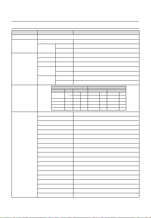
Specifi cations
SPECIFICATIONS
Items Sub-items SCC-B2333N
Camera Type
Image
Scanning
Min. Scene
Illumination
Functions
Device 1/3” Super-HAD IT CCD
Pixels
System Interlace
Scanning Line 525 lines
Frame 30frame/1sec
Horizontal
Frequency
Vertical
Frequency
Sens-up F No. Level DAY NIGHT
512 times 1.2 50 IRE 0.0008 Lux 0.00008 Lux
512 times 1.2 30 IRE 0.00047 Lux 0.000047 Lux
512 times 1.2 15 IRE 0.00023 Lux 0.000023 Lux
Number of Privacy Zone 12 (Polygonal Method)
Day/Night DAY/NIGHT/AUTO/EXT
Motion Detection OFF/Tracking/Detection
eXtended Dynamic Range(XDR) Off/On (Level Setting)
D-Zoom x1 ~ x16 (x0.1 STEP)
PIP Off/On
High Speed Shutter 1/60 ~ 1/10Ksec (OSD/External Control)
Flickerless Off/On
Sens-Up x2 ~ x512
BLC Off/On (Area Setting)
AGC Off/On (Max.Level Setting)
ELC Off/On ( ~ 1/200K sec)
Line Lock Off/On (Phase Control)
Camera ID Off/On (Max.54ea/2Line)
White Balance ATW1/ATW2/AWC/3200K/5600K
Digital Noise Reduction(DNR) Off/On (Adaptive 3D+2D)
Digital Image Stabilization(DIS)
Intelligent Video Fixed/Moved, Fence
Etc. Function Detail, Reverse(H/V), Posi/Nega
CCTV Camera (DAY/NIGHT)
Total 811 x 508
Effective 768 x 494
Internal Mode 15,734 Hz
Line-lock Mode 15,750 Hz
Internal Mode 59.94 Hz
Line-lock Mode 60 Hz
Condition Min. Scene illumination
OFF 1.2 50 IRE 0.4 Lux 0.04 Lux
OFF 1.2 30 IRE 0.24 Lux 0.024 Lux
OFF 1.2 15 IRE 0.12 Lux 0.012 Lux
Off/On
28 – DIGITAL COLOR CAMERA

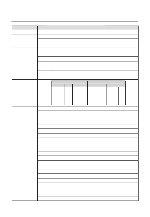
Specifi cations
Items Sub-items SCC-B2333N
Resolution
Video Output
S/N Ratio
Lens
Alarm
Remote
Control
Environmental
Conditions
Power
Physical
Specifi cation
Horizontal 600 TV Lines
Vertical 350 TV Lines
- VBS 1.0Vp-p, 75 Ω
S/N Ratio Approx. 52dB
Lens Drive Type MANUAL/AI(VIDEO/DC)
Mount Type CS/C
Input N/A
Output 1 Output
Coaxitron (Data On Coax cable) Yes (with SCX-RD100)
RS-485 Yes (Multi Protocol, 8ea)
Operating Temperature -10˚C ~ +50˚C
Humidity Less than 90%
Power Requirement
Power Consumption
(With DC Lens)
LED Indicator Yes
Dimensions
(WxHxD)
Weight
Color Body Silver
Net 64(W) x 58(H) x 109.2(D) mm
Package 173(W) x 99(H) x 115(D) mm
Net 305g
Package 530g
AC24V ± 10%(60Hz ± 0.3Hz)
DC12V ± 10%
In normal operation : 2.3W
In switching the DAY/NIGHT fi lter : 2.8W
ENG
English – 29
Specifi cations
Items Sub-items SCC-B2333P / SCC-B2033P
Camera Type
Image
Scanning
Min. Scene
Illumination
Functions
Resolution
Device 1/3” Super-HAD IT CCD
Pixels
System Interlace
Scanning Line 625 lines
Frame 25frame/1sec
Horizontal
Frequency
Vertical
Frequency
Sens-up F No. Level DAY NIGHT
512 times 1.2 50 IRE 0.0008 Lux 0.00008 Lux
512 times 1.2 30 IRE 0.00047 Lux 0.000047 Lux
512 times 1.2 15 IRE 0.00023 Lux 0.000023 Lux
Number of Privacy Zone 12 (Polygonal Method)
Day/Night DAY/NIGHT/AUTO/EXT
Motion Detection OFF/Tracking/Detection
eXtended Dynamic Range(XDR) Off/On (Level Setting)
D-Zoom Max. x16
PIP Off/On
High Speed Shutter 1/50 ~ 1/10Ksec (OSD/External Control)
Flickerless Off/On
Sens-Up x2 ~ x512
BLC Off/On (Area Setting)
AGC Off/On (Max.Level Setting)
ELC Off/On ( ~ 1/200K sec)
Line Lock Off/On (Phase Control)
Camera ID Off/On (Max.54ea/2Line)
White Balance ATW1/ATW2/AWC/3200K/5600K
Digital Noise Reduction(DNR) Off/On (Adaptive 3D+2D)
Digital Image Stabilization(DIS)
Intelligent Video Fixed/Moved, Fence
Etc. Function Detail, Reverse(H/V), Posi/Nega
Horizontal 600 TV Lines
Vertical 350 TV Lines
CCTV Camera (DAY/NIGHT)
Total 795 x 596
Effective 752 x 582
Internal Mode 15,625 Hz
Line-lock Mode 15,625 Hz
Internal Mode 50 Hz
Line-lock Mode 50 Hz
Condition Min. Scene illumination
OFF 1.2 50 IRE 0.4 Lux 0.04 Lux
OFF 1.2 30 IRE 0.24 Lux 0.024 Lux
OFF 1.2 15 IRE 0.12 Lux 0.012 Lux
Off/On
30 – DIGITAL COLOR CAMERA

Specifi cations
Items Sub-items SCC-B2333P / SCC-B2033P
Video Output
S/N Ratio
Lens
Alarm
Remote
Control
Environmental
Conditions
Power
Physical
Specifi cation
- VBS 1.0Vp-p, 75 Ω
S/N Ratio Approx. 52dB
Lens Drive Type MANUAL/AI(VIDEO/DC)
Mount Type CS/C
Input N/A
Output 1 Output
Coaxitron (Data On Coax cable) Yes (with SCX-RD100)
RS-485 Yes (Multi Protocol, 8ea)
Operating Temperature -10˚C ~ +50˚C
Humidity Less than 90%
Power Requirement
Power Consumption
(With DC Lens)
LED Indicator Yes
Dimensions
(WxHxD)
Weight
Color Body Silver
Net
Package 173(W) x 99(H) x 115(D) mm
Net
Package
SCC-B2333P : AC24V ± 10%(50Hz±0.3Hz)
DC12V ± 10%
SCC-B2033P : AC220V ± 10%(50Hz±0.3Hz)
In Normal operation :
SCC-B2333P : 2.3W
SCC-B2033P : 2.9W
In switching the DAY/NIGHT fi lter :
SCC-B2333P :2.8W
SCC-B2033P : 3.4W
SCC-B2333P : 64(W) x 58(H) x 109.2(D) mm
SCC-B2033P : 64(W) x 58(H) x 129.2(D) mm
SCC-B2333P : Approx. 305g
SCC-B2033P : Approx. 395g
SCC-B2333P : Approx. 530g
SCC-B2033P : Approx. 620g
ENG
English – 31

Correct Disposal of This Product (Waste Electrical & Electronic Equipment)
(Applicable in the European Union and other European countries with separate collection systems)
This marking on the product, accessories or literature indicates that the product and its electronic accessories
(e.g. charger, headset, USB cable) should not be disposed of with other household waste at the end of their
working life. To prevent possible harm to the environment or human health from uncontrolled waste disposal,
please separate these items from other types of waste and recycle them responsibly to promote the sustainable
reuse of material resources.
Household users should contact either the retailer where they purchased this product, or their local government
office, for details of where and how they can take these items for environmentally safe recycling.
Business users should contact their supplier and check the terms and conditions of the purchase contract.
This product and its electronic accessories should not be mixed with other commercial wastes for disposal.

SCC-B2333(P)
SCC-B2033P
ЦВЕТНАЯ ЦИФРОВАЯ
КАМЕРА
руководство пользователя
удивительные возможности
Благодарим Вас за приобретение данного продукта компании Samsung.
Для получения более полного обслуживания
зарегистрируйте свое устройство по адресу:
www.samsungsecurity.com
RUS

Меры предосторожности
ВНИМАНИЕ
ОПАСНОСТЬ ПОРАЖЕНИЯ ЭЛЕКТРИЧЕСКИМ
ТОКОМ! НЕ ОТКРЫВАТЬ!
ВНИМАНИЕ: ВО ИЗБЕЖАНИЕ ПОРАЖЕНИЯ ЭЛЕКТРИЧЕСКИМ ТОКОМ НЕ ОТКРЫВАЙТЕ КРЫШКУ (ИЛИ ЗАДНЮЮ ПАНЕЛЬ)
УСТРОЙСТВА. ВНУТРИ ОТСУТСТВУЮТ ДЕТАЛИ, ОБСЛУЖИВАНИЕ КОТОРЫХ МОЖЕТ ВЫПОЛНЯТЬ ПОЛЬЗОВАТЕЛЬ.
ОБСЛУЖИВАНИЕ ДОЛЖНО ВЫПОЛНЯТЬСЯ КВАЛИФИЦИРОВАННЫМИ СПЕЦИАЛИСТАМИ.
Этот символ обозначает, что внутри устройства имеется опасное напряжение,
которое может привести к поражению электрическим током.
Этот символ указывает, что в документации на изделие имеется важная инструкция
по его использованию или обслуживанию.
ПРЕДУПРЕЖДЕНИЕ
Во избежание повреждений, следствием которых может быть пожар или поражение
•
электрическим током, не допускайте попадания данного изделия под дождь или в условия
высокой влажности.
ПРЕДУПРЕЖДЕНИЕ
Пользуйтесь только стандартным блоком питания, который указан в листе спецификаций.
1.
Использование любого другого блока питания может привести к пожару, поражению
электрическим током или к повреждению изделия.
Неправильное подключение блока питания или замена батареи может привести к взрыву,
2.
пожару, поражению электрическим током или к повреждению изделия.
Не подключайте несколько видеокамер к одному блоку питания. Превышение нагрузочной
3.
способности блока питания может привести к его перегреву или к пожару.
4.
Надежно вставьте вилку сетевого шнура в розетку сети переменного тока. Ненадежное
подключение может привести к пожару.
5.
При установке видеокамеры закрепите ее прочно и надежно. Падение видеокамеры может
привести к травме.
6.
Не кладите сверху на видеокамеру токопроводящие предметы (например, отвертки,
монеты и другие металлические предметы) и не ставьте на нее наполненные водой сосуды.
Невыполнение этих требований может привести к пожару, поражению электрическим
током или к травмам в результате падения этих предметов.
7.
Не устанавливайте изделие во влажных, запыленных или покрытых копотью помещениях.
Невыполнение этого требования может привести к пожару или к поражению электрическим
током.
8.
Если вы почувствуете необычный запах или обнаружите дым, выходящий из изделия,
прекратите эксплуатацию. В этом случае следует немедленно отсоединить изделие от
источника питания и связаться с сервисным центром. Продолжение эксплуатации изделия в
таком состоянии может привести к пожару или к поражению электрическим током.
2 – ЦВЕТНАЯ ЦИФРОВАЯ КАМЕРА

Меры предосторожности
При обнаружении неисправности в изделии свяжитесь с ближайшим сервисным центром.
9.
Никогда не разбирайте данное изделие и не вносите изменений в его конструкцию.
(Компания SAMSUNG не несет ответственности за проблемы, возникшие в результате
внесения изменений в конструкцию изделия или попыток самостоятельно выполнить
ремонт изделия).
При чистке изделия не разбрызгивайте на него воду. Это может привести к пожару или к
10.
поражению электрическим током
ВНИМАНИЕ
Не роняйте на изделие никакие предметы и не ударяйте по нему. Не устанавливайте
1.
изделие в местах с сильной вибрацией или вблизи источников магнитного поля.
Не устанавливайте изделие в помещениях с высокой температурой (выше 50°С),
2.
пониженной температурой (ниже -10°С) или высокой влажностью. Это может привести к
возгоранию или поражению электрическим током.
Если вы хотите переместить ранее установленное изделие на новое место, отключите перед
3.
этим питание изделия.
Во время грозы отсоедините шнур питания видеокамеры от розетки сети переменного тока.
4.
Невыполнение этого требования может привести к пожару или к повреждению изделия.
Устанавливайте изделие так, чтобы на него не падал прямой солнечный свет и чтобы рядом
5.
не было источников, излучающих тепло. Это может привести к пожару.
Изделие должно устанавливаться в помещении с хорошей вентиляцией.
6.
7.
Избегайте направлять видеокамеру прямо на очень яркие объекты, например, на солнце,
так как это может привести к повреждению матрицы ПЗС, формирующей изображение.
8.
Изделие должно быть защищено от воздействия капель или брызг воды и на него нельзя
помещать наполненные водой сосуды, например, вазы с цветами.
9.
Вилка сетевого шнура используется в качестве отсоединяющего от питания устройства и к
ней всегда должен быть обеспечен легкий доступ.
RUS
Pyccкий – 3

Важные инструкции по технике безопасности
Прочтите эти правила.
1.
Сохраните эти правила.
2.
Принимайте во внимание все предупреждения.
3.
Следуйте всем правилам.
4.
Не используйте изделие вблизи воды.
5.
Чистите изделие только сухой салфеткой.
6.
Не загораживайте никакие вентиляционные отверстия. Выполните установку изделия в соответствии с
7.
инструкциями изготовителя.
Не устанавливайте изделие рядом с источниками тепла, такими, как радиаторы, решетки системы
8.
отопления, или другими устройствами, которые генерируют тепло (включая усилители).
В целях безопасности не отказывайтесь от использования вилок поляризованного или заземляющего
9.
типа. Вилка поляризованного типа имеет два ножевых контакта, один из которых шире другого.
Вилка заземляющего типа имеет два контакта и третий заземляющий штырь. Широкое лезвие третьего
заземляющего штыря предусмотрено для вашей безопасности. Если вилка поставляемого вместе с
аппаратом шнура питания не подходит для вашей розетки, попросите опытного электрика заменить
старую розетку.
Не наступайте на шнур питания и не допускайте его защемления, особенно вблизи
10.
от штепсельной вилки, в месте подключения к розетке и там, где шнур выходит из
изделия.
Пользуйтесь только теми приспособлениями/ принадлежностями, которые
11.
рекомендованы изготовителем.
Используйте изделие только с тележкой, кронштейном, штативом, держателем или
12.
подставкой, предусмотренными изготовителем или поставляемыми в комплекте с
изделием.
Перед перемещением изделия отсоедините его от электросети. Если используется тележка,
13.
соблюдайте осторожность при перемещении тележки с изделием, чтобы избежать повреждения
изделия или травмы при опрокидывании.
14.
Все работы, связанные с техническим обслуживанием изделия, должны выполняться
квалифицированными специалистами по техническому обслуживанию. Обслуживание изделия
требуется выполнять, когда изделие получило какое-либо повреждение, например, был поврежден
его шнур питания или вилка шнура питания, внутрь изделия попала жидкость или посторонние
предметы, изделие подверглось воздействию дождя или влаги, изделие не работает должным
образом, а также после падения изделия.
4 – ЦВЕТНАЯ ЦИФРОВАЯ КАМЕРА

Содержание
Введение
Функции 6
УСТРОЙСТВО И ПРИНАДЛЕЖНОСТИ 7
Компоненты видеокамеры и их назначение 8
Установка
Разъем для подключения объектива с автоматической диафрагмой 11
Установка объектива 11
Подключение кабелей и проверка работоспособности камеры 12
Использование экранного меню
Использование значков в меню 13
Ochobhoe mehю 13
Пpoфиль 14
Hactp. кamepы 16
C-ma otcлeж-я 22
Настройка зоны конфиденциальности 24
Другой тв 25
Cbязь 26
Иhф. o cиcteme 26
Язык 26
Технические характеристики
Технические характеристики 28
RUS
Pyccкий – 5

Введение
ФУНКЦИИ
Высокое разрешение
❖
Высокое разрешение видеокамеры 600 телевизионных линий обеспечивается с помощью использования
•
полностью цифровой обработки изображения и применения современных цифровых алгоритмов и технологий.
❖
Интеллектуальное обнаружение и отслеживание движения
•
Эта интеллектуальная функция позволяет автоматически обнаруживать движение объекта. Вы можете
создавать виртуальный барьер, при прохождении объектов через которую, будет подаваться сигнал тревоги.
XDR (расширенный динамический диапазон)
❖
Активное управление параметром гамма-коррекции, характеризующимся возможностью корректировки
•
внешнего яркостного контраста в определенном пикселе для определения оптимальной видимости.
ДЕНЬ/НОЧЬ
❖
Это функция, которая при низкой освещенности отключает ИК-фильтр, в результате чего увеличивается
•
чувствительность видеокамеры.
❖
Высокая чувствительность
Данная функция позволяет создавать изображения с высокой чувствительностью с помощью новейшей
•
камеры SONY Super-HAD IT CCD.
Работа при низкой освещенности
❖
В видеокамере имеется функция работы при низкой освещенности и функция День/Ночь, которые
•
базируются на технологии цифровой обработки сигнала и позволяют использовать видеокамеру при очень
низкой внешней освещенности.
Превосходная компенсации встречной засветки
❖
Если позади объекта находится источник яркого света или солнце, то данная видеокамера выполняет
•
компенсацию затемнения изображения, вызванного встречной засветкой, и обеспечивает получение
нормального изображения.
❖
Цифровая синхронизация развертки с частотой сети переменного тока
•
В данной видеокамере используется полностью цифровая синхронизация развертки от сети переменного
тока, которая непосредственно подстраивает синхронизацию кадровой развертки к частоте сети и
улучшает управляемость и надежность видеокамеры.
Настройка выходного сигнала
❖
Имеется возможность выполнить следующие настройки выходного видеосигнала: перевернуть
•
изображение (относительно горизонтальной оси, вертикальной оси, или обеих осей), задать зону для
защиты от вторжения в частную жизнь, отрегулировать четкость изображения по горизонтали и по
вертикали, а также использовать цифровое увеличение изображения.
Экранное меню
❖
Экранное меню предназначено для отображения состояния камеры и для настройки функций в
•
диалоговом режиме.
❖
Связь через коаксиальный кабель
Это функция дистанционного управления, благодаря которой управляющие сигналы подаются по коаксиальному
•
кабелю (предназначен для передачи видеосигнала). В случае установки или ремонта данная функция позволяет
управлять контроллером связи (приобретается дополнительно) без использования дополнительных кабелей.
6 – ЦВЕТНАЯ ЦИФРОВАЯ КАМЕРА
УСТРОЙСТВО И ПРИНАДЛЕЖНОСТИ
УСТРОЙСТВО И ПРИНАДЛЕЖНОСТИ❖
Основное устройство
•
Введение
Принадлежности
•
Держатель
видеокамеры
(основание)
Переходник для
объектива с
С-креплением
Kamepa
Руководство
пользователя
Разъем для подключения
объектива с
автоматической
диафрагмой
Pyccкий – 7
RUS

Введение
КОМПОНЕНТЫ ВИДЕОКАМЕРЫ И ИХ НАЗНАЧЕНИЕ
Вид сбоку❖
Отверстия для
крепления переходника
установочногокронштейна
Разъем для подключения
объектива с автоматической
диафрагмой
Кабель управления
объективом с
автоматической диафрагмой
Разъем для подключения объектива с автоматической диафрагмой
•
Через этот разъем на объектив с автоматической диафрагмой подается питающее напряжение, и
управляющий сигнал (видеосигнал или сигнал постоянного тока), с помощью которого осуществляется
управление скоростью затвора в объективе.
Кабель управления объективом с автоматической диафрагмой
•
По этому кабелю подается питание и сигналы от камеры для управления объективом с автоматической
ирисовой диафрагмой.
Отверстия для крепления переходника установочного кронштейна
•
Эти отверстия используются для крепления винтами переходника установочного кронштейна, который
является частью кронштейна, на котором устанавливается видеокамера.
Примечание :
Пятна с поверхности объектива видеокамеры следует аккуратно удалять с помощью специальной салфетки для протирки
–
оптики или с помощью хлопчатобумажной ткани, смоченной в этиловом спирте.
Объектив
видеокамеры
8 – ЦВЕТНАЯ ЦИФРОВАЯ КАМЕРА
Введение
Задняя панель❖
<AC24/DC12V (SCC-B2333(P))>
n
p
r
<AC220V~240V(SCC-B2033P)>
n
s
o
q
s
RUS
o
p
q
Pyccкий – 9

Введение
n Разъем входов/выходов
В этом разъеме имеются входные и выходные порты для сигналов управления RS-485, переключения
режимов ДEHЬ/HOЧЬ, а также сигналов выдачи предупреждений.
№ Назначение Описание
1 ALARM OUT
2 GND Порт заземления.
3 GND Порт заземления.
4 SHUTTER (S0)
5 SHUTTER (S1)
6 SHUTTER (S2)
7 5V OUT
8
DAY/NIGHT IN
9 RS-485 DATA– Это порт предназначен для подключения к сигнальной линии RS-485 DATA–.
10 RS-485 DATA+ Это порт предназначен для подключения к сигнальной линии RS-485 DATA+.
o Переключатель SETUP (Настройка)
Этот выключатель используется для настройки функции или свойства. При нажатии этого
переключателя на 2 секунды или более отображается меню OCHOBHOE MEHЮ.
ef
(Влево/Вправ)
cd
(Вверх/Вниз) :
: При нажатии этого переключателя, когда отображается меню, выбранная функция
подтверждается. Нажмите эту кнопку для входа в подменю.
p Светодиодный индикатор включения питания
При подаче на видеокамеру питающего напряжения загорается красный светодиод.
q Порт видеовыхода
Подключается к порту видеовхода монитора и выдает видеосигналы.
r GND
гнездо заземления.
s Порт для подключения питания
К этому гнезду подключается шнур питания (блок питания).
10 – ЦВЕТНАЯ ЦИФРОВАЯ КАМЕРА
Выходной порт сигнала тревоги для обнаружения движения (с разомкнутым коллектором)
Это порт для выбора режима внешнего высокоскоростного затвора.
При подключении к сети с низким напряжением (0 В) включение выполняется за счет
внутреннего источника напряжения.
Это порт для выбора режима внешнего высокоскоростного затвора.
При подключении к сети с низким напряжением (0 В) включение выполняется за счет
внутреннего источника напряжения.
Это порт для выбора режима внешнего высокоскоростного затвора.
При подключении к сети с низким напряжением (0 В) включение выполняется за счет
внутреннего источника напряжения.
Порт подачи питания для RS-485 JIG.
Используется в пределах номинального питания +5В=, 100 мА
Это порт предназначен для переключения режимов ДEHЬ/HOЧЬ.
Высокое (+3 В~+5 В постоянного тока) : Режим ДEHЬ(ЦBETHOE),
Низкий (0 В) : Режим HOЧЬ(Ч-Б)
: Нажатием переключателя влево или вправо можно перемещаться в меню влево
или вправо или изменять отображаемое значение.
Нажатием переключателя вверх или вниз можно перемещаться по пунктам меню вверх
или вниз.
РАЗЪЕМ ДЛЯ ПОДКЛЮЧЕНИЯ
ОБЪЕКТИВА С АВТОМАТИЧЕСКОЙ
ДИАФРАГМОЙ
Подсоедините зачищенные концы проводов
кабеля сигналов управления затвором к разъему
для подключения объектива с автоматической
диафрагмой, как показано в следующей таблице:
Объектив с
управлением
№
от сигнала
контакта
постоянного
тока
1 Damp(–) Питание (+12 В)
2 Damp(+) Не подключен
3 Drive(+) Видеосигнал
4 Drive(–) Земля
Примечание :
В меню можно выбрать тип управления объективом.
–
Объектив с
управлением от
видеосигнала
Установка
УСТАНОВКА ОБЪЕКТИВА
Когда используется объектив с CSкреплением
Вверните в видеокамеру объектив с CSкреплением по часовой стрелке, как показано на
рисунке ниже:
Объектив с
CS-креплением
CS 렌즈
Когда используется объектив с C-креплением
Вверните в видеокамеру переходник для
объектива с С-креплением по часовой стрелке
и затем вверните в переходник объектив с Скреплением до упора, как показано на рисунке
ниже.
Объектив с
C-креплением
C 렌즈
RUS
Pyccкий – 11

Установка
ПОДКЛЮЧЕНИЕ КАБЕЛЕЙ И
ПРОВЕРКА РАБОТОСПОСОБНОСТИ
КАМЕРЫ
①
Подсоедините один конец кабеля BNC к
порту VIDEO OUT на задней панели камеры.
② Подсоедините другой конец кабеля BNC к
порту VIDEO IN монитора.
Вход видеосигнала на задней
панели монитора
Кабель BNC
1
.
A
L
A
R
2
.
A
G
M
N
O
D
3
U
.
T
G
N
5
.
D
S
4
.
H
S
U
H
6
T
U
.
T
S
T
E
T
H
R
E
U
(
S
R
7
T
1
(
.
T
S
)
5
E
O
V
R
)
(
O
S
8
U
2
.
)
T
D
A
Y
/
N
I
G
H
T
I
N
1
2
3
4
5
6
7
8
Гнездо видеовыхода
Наконец подсоедините к камере блок
③
питания. Можно подсоединить две жилы
кабеля от блока питания ко входу питания
видеокамеры с помощью отвертки с плоским
лезвием, как показано ниже. (ЗЕМЛЯ: жила
кабеля с белой полосой на изоляции).
1
.
A
L
A
R
2
.
A
G
M
N
O
D
3
U
.
T
G
N
5
.
D
S
4
.
H
S
U
H
6
T
U
.
T
S
T
E
T
H
R
E
U
(S
R
7
T
1
(
.
T
S
)
5
E
O
V
R
)
(S
O
8
U
2
.
)
T
D
A
Y
/
N
I
G
H
T
I
N
1 2 3 4 5 6 7 8
Примечание :
Может использоваться источник питания 24 В
–
переменного тока или 12 В постоянного тока
(полярность подключения не имеет значения)
12 – ЦВЕТНАЯ ЦИФРОВАЯ КАМЕРА

Использование экранного меню
ИСПОЛЬЗОВАНИЕ ЗНАЧКОВ В МЕНЮ
(3ABEPШEHИE)
•
Выход из настроек меню.
Перед выходом из настроек меню выберите
СОХРАНИТЬ для сохранения настроек или
нажмите BЫX.Б/COXР для отмены.
(ВОЗВРАТ)
•
Возврат к предыдущему меню.
(ИСХОДНАЯ ПОЗИЦИЯ)
•
Возврат к главному меню.
(СОХРАНИТЬ)
•
Используется для сохранения настроек
следующих параметров: 3OHA MACKИP.,
ЧACTHAЯ ЗOHА и т.д.
Сохранив настройки один раз, они не будут
изменяться, даже если нажать BЫX.Б/COXР в
меню.
(УДАЛИТЬ)
•
Используется для удаления настроек следующих
параметров: 3OHA MACKИP., ЧACTHAЯ ЗOHА
и т.д.
Удалив настройки один раз, они не будут
восстановлены, даже если нажать ВЫХ.Б/СОХР
в меню.
OCHOBHOE MEHЮ
ÃÃOCHOBHOE MEHЮÃÃ
ПPOФИЛЬ
HACTP. КAMEPЫ
C-MA OTCЛEЖ-Я
ЧACTHAЯ ЗOHA
ДP. HACTPOЙКИ
CBЯЗЬ
ИHФ. O CИCTEME
ЯЗЫК
ПPOФИЛЬ
•
Можно задать режим в соответствии с
условиями установки камеры.
HACTP. КAMEPЫ
•
Настройка функций камеры и даты.
C-MA OTCЛEЖ-Я
•
Можно выполнить настройку функций
обнаружения движения, отслеживания и т.д.
ЧACTHAЯ ЗOHA
•
Можно выполнить настройку
конфиденциальности.
•
ДP. HACTPOЙКИ
Можно восстановить заводские настройки по
умолчанию и выполнить другие операции.
•
CBЯЗЬ
Настройка параметров контроллера связи
RS-485.
•
ИHФ. O CИCTEME.
Отображение информации о системе, а также
сведений о версии камеры и параметрах связи.
ЯЗЫК
•
Выберите предпочтительный язык из списка
поддерживаемых языков.
RUS
Pyccкий – 13

Использование экранного меню
И
ПPOФИЛЬ
e
ПPOФИЛЬ
f
CTAHДAPTHЫЙ
Ã
ITS
ФOHOB.CBET
ДEHЬ/HOЧЬ
ИГPA
ПOЛЬ3OB
В меню ПРОФИЛЬ можно сразу же выполнить настройку следующих параметров камеры.
Меню “HACTP. КAMEPЫ”
Предыдущее
меню
ДИAФPAГMA ALC ALC ALC ALC ALC
ДBИЖEHИE
ЦШП CPEДN. CPEДN. CPEДN. CPEДN. CPEДN.
ЗATBOP BЫКЛ ABTO1/250 BЫКЛ BЫКЛ BЫКЛ
HAKOПЛEHИE
XDR CPEДN. CPEДN. CPEДN. CPEДN. CPEДN.
ДEHЬ/HOЧЬ ABTO ABTO ДEHЬ ABTO ДEHЬ
CTAHДAPTHЫЙ
Подменю
ALC -- ---
OБЪEKTИB DC DC DC DC DC
УPOBEHЬ 0 0 0 0 0
ФOHOB.
BЫКЛ BЫКЛ BLC BЫКЛ BЫКЛ
CBET
(OЧ.БЫCTP.)---
ABTOx4 ABTOx2 ABTOx4 ABTOx4 ABTOx4
HOЧЬ - - - - -
BCПЫШКA BЫКЛ BКЛ BЫКЛ BЫКЛ BЫКЛ
BHEШHИЙ - - - - -
BCПЫШКA BЫКЛ BКЛ BЫКЛ BЫКЛ BЫКЛ
ITS ФOHOB.CBET ДEHЬ/HOЧЬ ИГPA
(OЧ.БЫCTP.)--- HOPM. (OЧ.БЫCTP.)--- MEДЛ.
14 – ЦВЕТНАЯ ЦИФРОВАЯ КАМЕРА

Использование экранного меню
Меню “HACTP. КAMEPЫ”
Предыдущее
меню
БAЛAHC
БEЛOГO
ЧETКOCTЬ 2 2 2 2 2
ITS
❖
CTAHДAPTHЫЙ
Подменю
ДEHЬ ДEHЬ/HOЧЬ ДEHЬ ДEHЬ/HOЧЬ ДEHЬ
ДEHЬ - - - - -
PEЖИM ATW2 ATW1 ATW1 ATW1 ATW1
КPACHЫЙ 0 0 0 0 0
CИHИЙ 0 0 0 0 0
HOЧЬ - - - - -
Разрешается настройка
ЯPKOCTЬ
пользователем
PEЖИM BЫКЛ ATW2 BЫКЛ ATW2 BЫКЛ
Разрешается настройка
КPACHЫЙ
пользователем
Разрешается настройка
CИHИЙ
пользователем
ITS ФOHOB.CBET ДEHЬ/HOЧЬ ИГPA
CPEДN.
0
0
Разрешается настройка
пользователем
Разрешается настройка
пользователем
Разрешается настройка
пользователем
CPEДN.
0
0
Разрешается настройка
Разрешается настройка
Разрешается настройка
пользователем
пользователем
пользователем
Настройка выполняется автоматически и позволяет без труда проверить условия движения.
❖
ФOHOB.CBET
Настройка выполняется автоматически и позволяет различить объект на фоне в условиях плохого заднего
света.
ДEHЬ/HOЧЬ
❖
Настройка выполняется автоматически для оптимизации в соответствии с условиями съемки днем или
ночью.
ИГPA
❖
Настройка выполняется автоматически и позволяет снимать изображение в условиях обычного
внутреннего освещения.
RUS
Pyccкий – 15
Использование экранного меню
И
ID КAMEPЫ [BЫКЛ, BКЛ]
HACTP. КAMEPЫ
eHACTP. КAMEPЫf
ID КAMEPЫ BЫКЛ
ДИAФPAГMA ALC
ДBИЖEHИE (OЧ.БЫCTP.)---
ЦШП CPEДN.
ЗATBOP BЫКЛ
HAKOПЛEHИE ABTO X4
HEMEPЦAЮЩEE (BЫКЛ)--XDR CPEДN.
ДEHЬ/HOЧЬ ABTO
БAЛAHC БEЛOГO
ЦИФP УBEЛИЧEHИE
ЧETКOCTЬ [2]
КAДP CИHXP. BHУTP
APУ ЦBETA
ИHBEPTИP. BЫКЛ
ПOЗ/HEГATИB +
PIP BЫКЛ
DIS BЫКЛ
Настройка общих функций модуля камеры с
увеличением.
Для выбора элемента меню используйте
переключатель
d
c
HИЗКИЙ
d
c
cdef
.
BЫКЛ
❖
ID КAMEPЫ
ABCDEFGHIJKLMNOPQRSTUVWXYZ0
123456789 :?-+*()/
CДB
ffee
CДB MECTO
KAMEPA-1..................
...........................
Меню ID КАМЕРЫ используется для назначения
камере уникального имени. Если нажать
переключатель SETUP, когда открыто меню ID
КАМЕРЫ, то отобразится соответствующий экран.
Для ID КAMEPЫ можно ввести до 54
буквенно-цифровых или специальных знаков.
Выберите MECTO и нажмите переключатель
SETUP для перехода к разделу ID КAMEPЫ.
❖
ДИAФPAГMA [ALC, ELC]
Меню ДИАФРАГМА используется, если
требуется отрегулировать интенсивность
радиации, поступающей в камеру. ALC
(автоматическая регулировка освещенности)
•
ALC (
автоматическая регулировка освещенности
① Если нажать переключатель SETUP,
когда открыто подменю ALC, отобразится
соответствующий экран.
ALC
OБЪEKTИB DC
УPOBEHЬ [00]----I----
ФOHOB.CBET BЫКЛ
Меню ОБЪЕКТИВ используется, если
выбран объектив типа AI.
Для нормальной работы выберите DC для
объектива типа DC, а для объектива типа
BИДEO выберите ВИДЕО.
)
16 – ЦВЕТНАЯ ЦИФРОВАЯ КАМЕРА

Использование экранного меню
Меню УРОВЕНЬ используется для
регулировки общей яркости, “+”
используется для увеличения яркости, а “–”
– для уменьшения.
②
Если для параметра ФОНОВ.СВЕТ установить
значение BLC, отобразится меню, в котором
можно задать область BLC.
Можно задать нужную зону BLC,
определив размер и положение.
ALC
OБЪEKTИB DC
УPOBEHЬ [00]----I----
ФOHOB.CBET BLC
OБЛACTЬ ПOЛЬЗOBAT.
<PAЗMEP>
<MECTO>
Если в условиях интенсивного фонового цвета
используется обычная камера, то объект на
экране будет темным под влиянием фонового
света. Для решения данной проблемы можно
воспользоваться функцией BLC (компенсация
заднего света), позволяющей повысить
четкость изображения в условиях очень
высокой контрастности.
ELC (
электронная регулировка освещенности
•
Если нажать переключатель SETUP, когда
①
выбрано подменю ELC, отобразится
соответствующий экран. Функцию ELC
(электронная регулировка освещенности)
можно включить или выключить.
ELC
УPOBEHЬ [00]----I----
ФOHOB.CBET BЫКЛ
② Так же как и для настройки ALC, можно
указать область BLC.
ELC
УPOBEHЬ [00]----I----
ФOHOB.CBET BLC
OБЛACTЬ ПOЛЬЗOBAT.
<PAЗMEP>
<MECTO>
APУ
❖
[BЫКЛ, OЧEHЬ HИ3KИЙ, HИЗКИЙ, CPEДN.,
BЫCOКИЙ, OЧEHЬ BЫCOK, ПOЛЬЗOBAT., ФИKC.]
Меню АРУ (автоматическая регулировка усиления)
используется для установки уровня АРУ камеры.
Если функция АРУ активна, камера автоматически
повышает уровень чувствительности, усиливая
видеосигнал в случае, когда мощность сигнала
понижается ниже обычного значения.
Если в меню НАКОПЛЕНИЕ выбран режим
ВЫКЛ или ФИКС., можно указать уровень АРУ.
Если нажать переключатель SETUP, когда
открыто подменю ПОЛЬЗОВАТ., отобразится
соответствующий экран.
)
AGC ПOЛЬ3OB.
УPOBEHЬ [16]
В режиме ПОЛЬЗОВАТ. уровень можно разбить на
16 ступеней в порядке ОЧЕНЬ НИЗКИЙ - ОЧЕНЬ
ВЫСОК в соответствии с вашими предпочтениями.
RUS
Pyccкий – 17

Использование экранного меню
И
AGC ФИKC.
УPOBEHЬ [01]
Если нажать переключатель SETUP, когда
открыто подменю ФИКС., отобразится
соответствующий экран.
Поскольку фиксированное значение параметра
АРУ используется в режиме ФИКС., перед
фиксацией можно выбрать один из 16
детализированных уровней в порядке ОЧЕНЬ
НИЗКИЙ – ОЧЕНЬ ВЫСОК.
Примечание :
Если для меню ДЕНЬ/НОЧЬ в разделе HACTP.
–
КAMEPЫ установлено значение АВТО, то меню APУ
будет отключено.
Если для функции HEMEPЦAЮЩEE установлено
–
значение ВКЛ, режим AGC ФИKC. будет отключен.
ДBИЖEHИE
❖
[OЧ.MEДЛ., MEДЛ., HOPM., БЫCTP., OЧ.БЫCTP.]
Меню ДВИЖЕНИЕ используется для регулировки
мощности уровня АРУ, необходимого для
управления движением камеры. Этот параметр
доступен только в том случае, если в меню
HAKOПЛEHИE выбрано значение АВТО.
Для параметра мощности уровня АРУ можно
выбрать одно из следующих значений: ОЧ.МЕДЛ.,
МЕДЛ., НОРМ., БЫСТР. и ОЧ.БЫСТР..
Для наблюдения за быстродвижущемся объектом в
условиях малой контрастности выберите значение
ОЧ.БЫСТР., а для наблюдения за малоподвижным
объектом в аналогичных условиях освещения
выберите значение ОЧ.МЕДЛ..
Примечание :
Если для меню ДЕНЬ/НОЧЬ в разделе HACTP.
–
КAMEPЫ установлено значение АВТО, то меню
ДBИЖEHИE будет отключено.
ЦШП
❖
[BЫКЛ,HИЗКИЙ,CPEДN.,BЫCOКИЙ,
ПOЛЬЗOBAT.(1~16)]
Можно выполнить настройку параметров
функции ЦШП (цифровое шумоподавление).
Снижение уровня помех на экране.
Эта функция особенно полезна для очень
искаженных изображений на экране.
Можно задать уровень, установив для
параметра ЦШП значение ПOЛЬЗOBAT.
❖
ЗATBOP
[BЫКЛ, ABTO 1/100(PAL:1/120), ABTO 1/250,
ABTO 1/500, ABTO 1/1000, ABTO 1/2000, ABTO
1/4000, ABTO 1/10000 , 1/100(PAL:1/120), 1/250,
1/500, 1/1000, 1/2000, 1/4000, 1/10000, BHEШHИЙ]
Меню ЗАТВОР используется для настройки
фиксированного высокоскоростного электронного
затвора, автоматического высокоскоростного
электронного затвора и внешнего высокоскоростного
электронного затвора (ВНЕШНИЙ).
Фиксированный высокоскоростной затвор имеет
7 скоростей в диапазоне от 1/100 (PAL:1/120) до
1/10000 секунды, которые обычно используется при
съемке быстродвижущегося объекта.
Автоматический высокоскоростной электронный
затвор в условиях высокой контрастности работает так
же, как и фиксированный высокоскоростной затвор,
но при полном открытии диафрагмы в условиях
малой контрастности он выполняет автоматическую
фокусировку цели, как и в режиме ELС. Когда уровень
яркости нормализуется, будет включен режим
фиксированного высокоскоростного затвора.
Однако автоматический высокоскоростной
затвор работает надлежащим образом только в
камерах с объективами типа DC или ВИДЕО.
В режиме внешнего высокоскоростного
электронного затвора (ВНЕШНИЙ) можно выбрать
одну из 8 скоростей: ВЫКЛ, 1/100 (PAL:1/120)
- 1/10000. Принцип его работы аналогичен
принципу работы высокоскоростного электронного
затвора. Используя SHUTTER(S0), SHUTTER(S1)
и SHUTTER(S2) на задней панели, можно выбрать
нужный параметр.
Подсоедините каждый из разъемов к GND.
Описание хода работы см. в таблице ниже.
SHUTTER(S0) SHUTTER(S1) SHUTTER(S2)
BЫКЛ
(NTSC: 1/60,
BЫКЛ BЫКЛ BЫКЛ
PAL:1/50)
1/100
BКЛ BЫКЛ BЫКЛ
(PAL:1/120)
18 – ЦВЕТНАЯ ЦИФРОВАЯ КАМЕРА

Использование экранного меню
HEMEPЦAЮЩEE [BЫКЛ, BКЛ]
1/250 BЫКЛ BКЛ BЫКЛ
1/500 BКЛ BКЛ BЫКЛ
1/1000 BЫКЛ BЫКЛ BКЛ
1/2000 BКЛ BЫКЛ BКЛ
1/4000 BЫКЛ BКЛ BКЛ
1/10000 BКЛ BКЛ BКЛ
Примечание :
Если в режиме ДИАФРАГМА установлено значение ELC,
–
меню ЗАТВОР будет закрыто после завершения регулировки
яркости с помощью электронного затвора.
Если для параметра НАКОПЛЕНИЕ установлено значение
–
АВТО, то в меню ЗАТВОР будут доступны только значения
ВЫКЛ и АВТО.
Если в режиме НАКОПЛЕНИЕ выбрано значение ФИКС.,
–
меню ЗАТВОР будет отключено.
Если для функции НЕМЕРЦАЮЩЕЕ выбрано значение ВКЛ,
–
меню ЗАТВОР будет отключено.
HAKOПЛEHИE
❖
[BЫКЛ, ABTO X2, ABTO X4, ABTO X6, ABTO X8,
ABTO X12, ABTO X16, ABTO X24, ABTO X32, ABTO
X48, ABTO X64, ABTO X96, ABTO X128, ABTO
X256, ABTO X512, ФИKC. X2, ФИKC. X4, ФИKC.
X6, ФИKC. X8, ФИKC. X12, ФИKC. X16, ФИKC. X24,
ФИKC. X32, ФИKC. X48, ФИKC. X64, ФИKC. X96,
ФИKC. X128, ФИKC. X256, ФИKC. X512]
Автоматическое обнаружение уровня внешних шумов
в темноте или в условиях малой контрастности для
увеличения общего времени, при этом изображение
остается ярким и четким. Эта функция может также
использоваться в режиме ФИКС.
Примечание :
Если для параметра ЗАТВОР установлен режим фиксированного
–
электронного затвора или режим ВНЕШНИЙ, меню НАКОПЛЕНИЕ
будет отключено.
–
Если для функции HEMEPЦAЮЩEE установлено значение
ВКЛ, то режим ФИKC. в меню HAKOПЛEHИE будет отключен.
–
Если в меню ДИАФРАГМА установлено значение ELC, электронный
затвор будет контролировать уровень яркости, при этом для функции
НАКОПЛЕНИЕ нельзя выбрать режим ФИКС., а можно включить
режим ВЫКЛ или АВТО.
–
Если для параметра ЗАТВОР установлено значение АВТО, в меню
НАКОПЛЕНИЕ можно выбрать режим ВЫКЛ или АВТО.
❖
Если установлено значение ВКЛ, будет зафиксирована
следующая скорость затвора - 1/100 (PAL:1/120)
секунды. Это поможет предотвратить возможное
искажение на экране вследствие несоответствия частоты
покадровой синхронизации и частоты мерцания света.
Примечание :
–
Если для функции ДИАФРАГМА установлено значение ELC,
меню Немерцающее будет отключено. Если в меню ЗАТВОР
выбраны режимы АВТО, ФИКС. или ВНЕШНИЙ, меню
Немерцающее будет отключено.
–
Если для функции НАКОПЛЕНИЕ выбран режим ФИКС., меню
Немерцающее будет отключено.
–
Если для функции APУ установлено значение ФИKC., функция
HEMEPЦAЮЩEE будет отключена.
❖
XDR (расширенный динамический диапазон)
[BЫКЛ, HИЗКИЙ, CPEДN., BЫCOКИЙ]
Активное управление параметром гамма-коррекции,
характеризующимся возможностью корректировки
внешнего яркостного контраста в определенном
пикселе для определения оптимальной видимости.
Выберите одно из следующих значений: ВЫКЛ,
НИЗКИЙ, СРЕДН. и ВЫСОКИЙ. Выбирая
значения, близкие к значению ВЫСОКИЙ,
можно повысить уровень компенсации.
❖
ДEHЬ/HOЧЬ
•
ДEHЬ
•
HOЧЬ
[ДEHЬ,HOЧЬ,ABTO,BHEШHИЙ]
Если установлено значение ДEHЬ, то
независимо от внешних условий будет включен
режим ДEHЬ.
Если установлено значение HOЧЬ, то независимо от
внешних условий будет включен режим черно-белого.
Если нажать переключатель SETUP, когда открыто
подменю HOЧЬ, отобразится меню, в котором для
параметра Вспышка можно установить значения
BЫКЛ/BКЛ.
Если для параметра ВСПЫШКА установлено значение
ВКЛ, сигнал вспышки будет выводиться вместе с
черно-белым композитным видеосигналом. Если для
параметра ВСПЫШКА установлено значение ВЫКЛ,
сигнал вспышки выводиться не будет.
Для параметра ВСПЫШКА можно установить
значение ВЫКЛ/ВКЛ или выбрать функцию вывода
сигнала вспышки в режиме HOЧЬ.
Pyccкий – 19
RUS

Использование экранного меню
И
ABTO
•
Камера выполнит автоматическое переключение
режимов ДEHЬ и HOЧЬ в соответствии с условиями
освещения.
Если нажать переключатель SETUP, когда
открыто подменю параметра АВТО, отобразится
соответствующий экран.
Для параметра ВСПЫШКА можно установить
значение ВЫКЛ/ВКЛ или выбрать функцию
вывода сигнала вспышки в режиме HOЧЬ.
Можно выбрать следующие значения: НИЗКИЙ,
СРЕДН. и ВЫСОКИЙ для яркости параметра
ДEHЬÆHOЧЬ. Эти значения указывают на уровень
яркости при переключении фильтра с цветного
на черно-белый. При выборе значения НИЗКИЙ,
затем ВЫСОКИЙ будет выполняться переключение
фильтра в условиях малой контрастности.
BЫДEPЖКA BPEM. для переключения
ДEHЬÆHOЧЬ - это время, которое требуется для
определения необходимости переключения фильтра.
Можно выбрать следующие значения: HИЗКИЙ,
CPEДN. и BЫCOКИЙ для яркости параметра
HOЧЬÆДEHЬ. Эти значения указывают на уровень
яркости при переключении фильтра с черно-белого
на цветной. При выборе значения HИЗКИЙ, затем
BЫCOКИЙ будет выполняться переключение
фильтра в условиях малой контрастности.
BЫДEPЖКA BPEM. для переключения
HOЧЬÆДEHЬ - это время, которое требуется для
определения необходимости переключения фильтра.
Меню МАСКИР. предназначено для того, чтобы
предотвратить ошибку переключения фильтра
или невозможность определить необходимость
переключения в случае существования ярких
световых пятен ночью.
При нажатии переключателя SETUP в пунктах 1
или 2 меню МАСКИР. отобразится меню, в котором
можно указать зону маскирования.
ABTO
BCПЫШКA BЫКЛ
ДEHЬÆHOЧЬ
ЯPKOCTЬ CPEДN.
BЫДEPЖКA BPEM. 2S
HOЧЬÆДEHЬ
ЯPKOCTЬ CPEДN.
BЫДEPЖКA BPEM. 5S
3OHA MACKИP. 1 2
•
❖
•
3OHA MACKИP.
<PAЗMEP>
<MECTO>
Можно указать зону Маскир. 1 и 2 одновременно.
Функция маскирования предназначена
исключительно для определения момента
переключения фильтра и определения чрезмерно
ярких пятен ночью, требующих маскировки.
Примечание :
Если для параметра ФОНОВ.СВЕТ установлено значение BLC,
–
функция ЗОНА МАСКИР. будет отключена.
BHEШHИЙ
Благодаря этому возможно автоматическое
переключение режимов ДEHЬ и HOЧЬ с
использованием интерфейса внешнего датчика.
БAЛAHC БEЛOГO [ДEHЬ/HOЧЬ]
Если требуется настроить цветовую схему,
используйте функцию БАЛАНС БЕЛОГО.
ДEHЬ
В режиме ДЕНЬ можно задать значения
цветов КРАСНЫЙ и СИНИЙ. Экран будет
отображаться в соответствии с заданными
настройками цвета.
БAЛAHC БEЛOГO
ДEHЬ/HOЧЬ ДEHЬ
PEЖИM AWC
КPACHЫЙ [00]----I--- CИHИЙ [00]----I--- УCИЛEHИE R [0248]
УCИЛEHИE B [0247]
Примечание :
Значения параметров УCИЛEHИE R и УСИЛЕНИЕ В
–
можно установить только в режиме AWC.
20 – ЦВЕТНАЯ ЦИФРОВАЯ КАМЕРА

Использование экранного меню
HOЧЬ
•
Режим НОЧЬ предназначен для настройки
баланса белого в соответствии с внешним
освещением.
Если для режима НОЧЬ установлено значение
ВЫКЛ, функция баланса белого будет всегда
работать с настройками, заданными в
режиме ДЕНЬ. Если установлено значение,
отличное от ВЫКЛ, камера будет работать с
настройками режима ДЕНЬ/НОЧЬ, заданными
в соответствии с уровнем яркости.
В режиме НОЧЬ можно установить значения
КРАСНЫЙ, СИНИЙ и ЯРКОСТЬ. Экран будет
отображаться в соответствии с заданными
настройками цвета.
БAЛAHC БEЛOГO
ДEHЬ/HOЧЬ HOЧЬ
ЯPKOCTЬ CPEДN.
PEЖИM AWC
КPACHЫЙ [00]----I--- CИHИЙ [00]----I--- УCИЛEHИE R [0248]
УCИЛEHИE B [0247]
Примечание :
Значения параметров УCИЛEHИE R и УСИЛЕНИЕ В
–
можно установить только в режиме AWC.
Если для параметра АРУ установлено значение ВЫКЛ
–
или ФИКС., невозможно получить доступ к меню
НОЧЬ.
Для настройки баланса белого
–
используются 5 следующих режимов.
•
ATW1(режим автоматического отслеживания
баланса белого 1): Камера может автоматически
регулировать цветовую температуру в реальном
времени в соответствии с внешними условиями.
Диапазон цветовых температур составляет 2500 K
– 9300 K.
•
ATW2: Диапазон цветовых температур составляет
2000 K – 10000 K.
•
AWC (автоматическое управление балансом
белого): Если нажать переключатель SETUP, когда
выбран соответствующий элемент, один раз будет
выполнена функция автоматической настройки
баланса белого.
•
3200K : Установка цветовой температуры 3200 K.
•
5600K : Установка цветовой температуры 5600 K.
–
КPACHЫЙ : Настройка глубины красного цвета.
–
CИHИЙ : Настройка глубины синего цвета.
–
УCИЛEHИE R/УCИЛEHИE B : Возможность
установки текущей цветовой температуры вручную.
–
ЯPKOCTЬ : Выберите уровень яркости, переключив
настройки режима ДЕНЬ на настройки режима НОЧЬ.
ЦИФP УBEЛИЧEHИE [BКЛ/BЫКЛ]
❖
Можно задать коэффициент и положение
цифрового увеличения. Если нажать
переключатель SETUP, когда для функции
ЦИФР УВЕЛИЧЕНИЕ установлено значение
ВКЛ, отобразится соответствующий экран.
После определения коэффициента и
положения увеличения функция цифрового
увеличения будет работать.
ЦИФP УBEЛИЧEHИE
KPATHOCTЬ [X1.0]
< MECTO >
-
MECTO : Если нажать переключатель SETUP, когда
изображение увеличено так же, как и форматное
соотношение, то будет просматриваться невидимая
область рабочего экрана. Аналогичный эффект
возможен при нажатии переключателя
Примечание :
Если заданный коэффициент цифрового увеличения больше 1x,
–
функция КРЫШКА будет отключена.
Функция ЦИФР УВЕЛИЧЕНИЕ позволяет увеличивать сам
пиксел, что может привести к ухудшению качества изображения.
ЧETКOCTЬ [0~3]
❖
Регулировка разграничения по горизонтали
или вертикали.
cdef
.
Pyccкий – 21
RUS

Использование экранного меню
И
КAДP CИHXP. [BHУTP, ЛИHИЯ]
❖
Выберите режим вертикальной синхронизации
для параметров ВНУТР или ЛИHИЯ.
Если установлен параметр ВНУТР, в камере будет
использоваться внутренняя синхронизация.
Если установлен параметр ЛИHИЯ, то для
синхронизации в камере будет использоваться
частота внешнего источника питания.
Можно настроить параметр ФAЗA CИHX. CETИ.
Примечание :
При использовании источника 12 В постоянного тока
–
для параметра КAДP CИHXP. устанавливается
значение BHУTP, которое невозможно изменить.
APУ ЦBETA [HИЗКИЙ , CPEДN., BЫCOКИЙ]
❖
Настройка цветовой температуры в
соответствии со значением АРУ.
ИHBEPTИP. [BЫКЛ, Г, B, Г/B]
❖
Отражение видеосигналов горизонтально,
вертикально или сразу в двух положениях.
ПOЗ/HEГATИB [+, –]
❖
Вывод исходного состояния сигнала или
отражение сигнала яркости видео.
PIP [BЫКЛ, BКЛ]
❖
Отображение дополнительного изображения
вместе с главным изображением на одном и том же
экране с помощью функции “Картинка в картинке”.
Примечание :
Если задано несколько частных зон и для параметра
–
УCT.ЧACT.3OHЫ установлено значение ВКЛ,
функция PIP будет отключена.
–
Если для функции C-MA OTCЛEЖ-Я выбран режим
КРЫШКА, меню функции PIP будет отключено.
DIS [BЫКЛ, BКЛ]
❖
С помощью функции цифровой стабилизации изображения
можно установить противоударную компенсацию.
Примечание :
Если для параметра DIS установлено значение ВКЛ,
–
зона компенсации будет увеличена в соответствии с
коэффициентом цифрового увеличения.
Если установить коэффициент цифрового увеличения
больше коэффициента увеличенной зоны для
компенсации, функция DIS будет отключена.
22 – ЦВЕТНАЯ ЦИФРОВАЯ КАМЕРА
C-MA OTCЛEЖ-Я
eC-MA OTCЛEЖ-Яf
ДBИЖEHИE BЫКЛ
УЛУЧWEHHЫЙ BЫКЛ
3OHA MACKИP.
ДИCПЛEЙ BКЛ
ЧУBCTBИT. [4]
PA3PEWEHNE [5]
BЫXOД TPEB.
В меню C-MA OTCЛEЖ-Я можно выбрать функцию
обнаружения и отслеживания движения объекта.
ДBИЖEHИE
❖
PEДEЛ]
OTCЛEЖИBAHИE
•
Обнаружение и отслеживание движущегося
объекта.
ONPEДEЛ
•
Обнаружение движущегося объекта.
Примечание :
Если установлено значение ОПРЕДЕЛ, функции ФИKC/ДBИЖ и
–
КРЫШКА в меню УЛУЧШЕННЫЙ включать не нужно.
УЛУЧWEHHЫЙ
❖
KPЫШKA]
Обнаружение движения объекта и отображение
изображения любого движущегося объекта перед
отслеживанием маршрута перемещения.
•
KPЫШKA
Используется для обнаружения объекта,
перемещающегося через указанные отметки
ЧEPTA или ОБЛАСТЬ.
В состоянии, когда выполняется обнаружение
движущегося объекта путем анализа
предыдущего и текущего кадров, движение
которых накладывается на определенную
область, система отображает сообщение
“ПEPEДAЧA”, если центральная линия объекта
пересекла линию, и отображает сообщение
“BOЙTИ” или “BЫXOД”, если через область
пройдет центральная точка.
1 2 3 4
[BЫКЛ,OTCЛEЖИBAHИE,ON
[BЫКЛ, ФИKC/ДBИЖ,

Использование экранного меню
KPЫШKA
ЧEPTA BЫКЛ
OБЛACTЬ BЫКЛ
Можно задать положение и направление
обнаружения для параметра ЧEPTA и размер и
положение для параметра ОБЛАСТЬ.
- Процедура установки линии
ЧEPTA
УPOBEHЬ ПИKC. [4]
<TOЧKИ>
HAПPABЛEHИE §¨
① Если нажать переключатель SETUP,
когда для параметра ЧEPTA установлено
значение ВКЛ, можно указать положение и
направление обнаружения линии.
② В случае изменения значения параметра
УPOBEHЬ ПИKC. для установки
положения выберите движущийся пиксел,
нажав переключатель
В меню <ТОЧКИ> можно указать исходное
③
положение линии, нажав переключатель SETUP
один раз, и указать следующее положение
линии, нажав переключатель еще раз.
Используйте переключатель cdef для
того, чтобы указать положение.
Установите каждое положение двух точке и
нажмите SETUP для завершения процедуры
установки положения.
④
Установив параметр НАПРАВЛЕНИЕ,
можно указать направление обнаружения.
Направление обнаружения, в основе
которого лежат две заданные точки, будет
отображаться на экране.
cdef
один раз.
- Процедура установки области
OБЛACTЬ
УPOBEHЬ ПИKC. [4]
<PAЗMEP>
<MECTO>
①
Если нажать переключатель SETUP, когда для
параметра ОБЛАСТЬ установлено значение ВКЛ,
можно указать положение и размер области.
② В случае изменения значения параметра
УPOBEHЬ ПИKC. для установки
положения выберите движущийся пиксел,
нажав переключатель
В меню <РАЗМЕР> нажмите переключатель
③
SETUP и используйте переключатель
cdef
Нажмите переключатель SETUP еще раз для
завершения процедуры задания размера.
④
В меню <МЕСТО> нажмите переключатель
SETUP и используйте переключатель
cdef
Нажмите переключатель SETUP еще раз для
завершения процедуры установки положения.
Примечание :
Если для параметра ЧEPTA функции КРЫШКА
–
установлено значение ВКЛ, значение ЧАСТНАЯ ЗОНА
12 будет не доступно.
Функции КРЫШКА, PIP, DIS и ЦИФР УВЕЛИЧЕНИЕ
(если заданный коэффициент цифрового увеличения
больше 1x) нельзя использовать одновременно.
–
На границе заданных значений параметров ОБЛАСТЬ и
ЧEPTA может произойти ошибка обнаружения функции
КРЫШКА. Это происходит, когда траектории движения
двух или более объектов накладываются друг на друга или
один объект перемещается в нескольких направлениях.
ФИKC/ДBИЖ
•
Если объект внезапно исчезает с экрана или появляется
из ниоткуда и остается неподвижным в течение
некоторого времени, то будет отображаться область.
Ошибка обнаружения (ФИKC/ДBИЖ) может
произойти по следующим причинам.
- Непрерывное перемещение нескольких
объектов в произвольных направлениях.
cdef
один раз.
для регулировки размера.
, чтобы указать положение.
Pyccкий – 23
RUS

Использование экранного меню
И
- Зафиксированный объект непрерывно
перемещается в одном направлении.
- Перемещение второго объекта накладывается
на перемещение первого.
3OHA MACKИP. [1~4]
❖
Укажите область исключения возможности обнаружения
для выполнения маскирования.
Выберите номер маски и укажите размер и положение.
3OHA MACKИP.
<PAЗMEP>
<MECTO>
ДИCПЛEЙ [BКЛ, BЫКЛ]
❖
Если для параметра ДИCПЛEЙ установлено
значение BКЛ, на экране будет отображаться
функция УЛУЧWEHHЫЙ в случае обнаружения.
ЧУBCTBИT. [1~7]
❖
Установите чувствительность обнаружения движения.
PA3PEWEHNE [1~5]
❖
Если установлена высокая чувствительность,
камера способна обнаруживать даже самое
незначительное перемещение объекта.
BЫXOД TPEBOГИ
❖
Если для нужного параметра меню установить значение
ВКЛ, камера будет издавать сигнал тревоги при
обнаружении соответствующего движения.
BЫXOД TPEBOГИ
ДBИЖEHИE BКЛ
ФИKC/ДBИЖ BКЛ
KPЫШKA
ЧEPTA BКЛ
OБЛACTЬ
BOЙTИ BКЛ
BЫXOД BКЛ
НАСТРОЙКА ЗОНЫ
КОНФИДЕНЦИАЛЬНОСТИ
eЧACTHAЯ ЗOHAf
1 2 3 4 5 6
7 8 9 10 11
УCT.ЧACT.3OHЫ BКЛ
CTИЛЬ
Функция ЧАСТНАЯ ЗОНА позволяет защитить
вашу частную зону. С помощью этой функции
экранируется частная зона, заданная во время
наблюдения. Можно указать до 12 частных зон.
Если для параметра УCT.ЧACT.3OHЫ установлено
значение ВКЛ, будет применены настройки
функции ЧАСТНАЯ ЗОНА.
Можно изменить стиль, чтобы выбрать размер и
цвет мозаики для параметра ЧАСТНАЯ ЗОНА.
eЧACTHAЯ ЗOHAf
1 2 3 4 5 6
7 8 9 10 11
УCT.ЧACT.3OHЫ BКЛ
CTИЛЬ ЦBETHOE
ЯPКOCTЬ [128]
КPACHЫЙ [128]
CИHИЙ [128]
С помощью переключателя
одно из значений параметра ЧАСТНАЯ ЗОНА (от
1 до 12).
Выберите одно из значений параметра ЧАСТНАЯ
ЗОНА 1~12 и нажмите переключатель SETUP
для подтверждения настройки. Можно указать
движущийся пиксел при изменении значения
параметра УPOBEHЬ ПИKC. для установки
положения.
12
MOЗAИКA1
12
cdef
выберите
24 – ЦВЕТНАЯ ЦИФРОВАЯ КАМЕРА

Использование экранного меню
УCT. ЧAC. ЗOHЫ1
УPOBEHЬ ПИKC. [4]
<TOЧKИ>
<ПO3ИЦИЯ>
- Процедура установки точки
Можно настроить положение 4 точек.
①
При нажатии переключателя SETUP в меню
<ТОЧКИ> отобразятся точки, доступные для
параметра ЧАСТНАЯ ЗОНА. Каждый раз при
нажатии переключателя SETUP доступные
точки будут перемещаться.
② С помощью переключателя
установите положение каждой точки.
Установите каждое положение четырех
точек и нажмите SETUP для завершения
процедуры установки положения.
- Процедура установки положения
Можно изменить положение всей зоны.
① С помощью переключателя SETUP в меню
<ПОЗИЦИИ> можно изменить общее
положение частной зоны.
② С помощью переключателя
измените положение и нажмите
переключатель SETUP для подтверждения
изменения.
Примечание :
Если указано несколько значений параметра ЧАСТНАЯ
–
ЗОНА и для параметра УCT.ЧACT.3OHЫ установлено
значение ВКЛ, функция PIP будет отключена.
Если указана 12-я ЧАСТНАЯ ЗОНА, то настройка
–
ЧEPTA функции КРЫШКА будет отключена.
cdef
cdef
ДРУГОЙ ТВ
eДP. HACTPOЙКИf
3ABOД.УCTAH.
ЦBETHOE Ч-Б
3ABOД.УCTAH.
❖
Будут восстановлены заводские настройки по
умолчанию.
Однако для параметров ПРОТОКОЛ,
CКOPOCTЬ(БOД), АДРЕС и ЯЗЫК заводские
настройки по умолчанию не восстанавливаются.
ЦBETHOE [Ч-Б, R/G/B]
❖
Можно задать цвет экранного меню: ЦBETHOE
или Ч-Б.
RUS
Pyccкий – 25
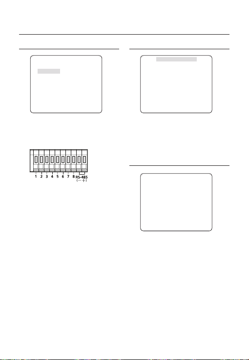
Использование экранного меню
И
CBЯЗЬ
eCBЯЗЬf
RS-485
ПPOTOКOЛ
CКOPOCTЬ(БOД) 9600
AДPEC 0
Меню СВЯЗЬ используется для выполнения
настройки параметров контроллера связи RS-485.
Подключение контроллера связи RS-485
выполнятся на задней панели камеры.
SAMSUNG
ИHФ. O CИCTEME
eИHФ. O CИCTEMEf
TИП 3_BOX_NOR_N
ПPOTOКOЛ
AДPEC 1
TИП CBЯЗИ RS-485,ПOЛOB.
CКOPOCTЬ(БOД)
CEPИЙHЫЙ № 000000000000000
BEPC. КAMEPЫ 0.50_090101
BEPC. ЭCППЗУ 0.50_090101
Можно просмотреть следующие сведения
о системе: протокол, адрес, скорость (бод),
серийный номер, версия камеры и версия
ЭCППЗУ.
SAMSUNG
9600
ЯЗЫК
[Разъем ввода/вывода камеры]
Используя переключатель
устройств связи укажите протокол, скорость
передачи данных в бодах и адрес (0~255).
ПPOTOКOЛ
❖
Выберите протокол связи.
CКOPOCTЬ(БOД)
❖
Выберите скорость передачи в бодах.
Примечание :
Скорость передачи в бодах различается в зависимости
–
от указанного протокола.
AДPEC
❖
Необходимо указать уникальный адрес для
каждой камеры в одной и той же сети RS-485.
Для управления определенной камерой
адрес камеры должен совпадать с адресом
устройства DVR или контроллера.
cdef
[0~255]
, для
Меню камеры поддерживает 5 языков.
Выберите предпочтительный язык.
eЯЗЫКf
ENGLISH
ÃPУCCKNЙ
POLSKI
ČESKY
TÜRKÇE
26 – ЦВЕТНАЯ ЦИФРОВАЯ КАМЕРА

Использование экранного меню
Таблица с начальными конфигурациями
❖
Конфигурация камеры
•
ID КAMEPЫ BЫКЛ
ДИAФPAГMA ALC
APУ OЧEHЬ BЫCOK
ДBИЖEHИE (OЧ.БЫCTP.)
ЦШП CPEДN.
ЗATBOP BЫКЛ
HAKOПЛEHИE
ABTO x4
HEMEPЦAЮЩEE (BЫКЛ)
XDR CPEДN.
ДEHЬ/HOЧЬ ABTO
ЦИФP УBEЛИЧEHИE BЫКЛ
ЧETКOCTЬ [2]
APУ ЦBETA CPEДN.
ИHBEPTИP. BЫКЛ
ПOЗ/HEГATИB +
PIP BЫКЛ
DIS BЫКЛ
КAДP CИHXP. BHУTP
RUS
Pyccкий – 27

Технические характеристики
ТЕХНИЧЕСКИЕ ХАРАКТЕРИСТИКИ
Пункты Подпункты SCC-B2333N
Тип камеры
Формирователь
Система
Минимальная
освещенность
сцены
Функции
Количество
сканирования Чересстрочная
Линии развертки
Кадры 30 кадров/сек
Частота
горизонтальной
развертки
Частота
вертикальной
развертки
Количество частных зон 12 (полигональный метод)
Детектор движения BЫКЛ/OTCЛEЖИBAHИE/ONPEДEЛ
Расширенный динамический
Цифровое увеличение x1 ~ x16 (x0.1 ШАГ)
Высокоскоростной затвор
Цифровое шумоподавление (ЦШП)
Цифровая стабилизация изображения
Интеллектуальное видео Фикс/Движ, Крышка
Другие функции Четкость, Инвертир. (Г/В), Поз/Негатив
28 – ЦВЕТНАЯ ЦИФРОВАЯ КАМЕРА
Камера CCTV (с функциями ДЕНЬ/НОЧЬ)
изображения 1/3” Super-HAD IT CCD
эффективных 811 x 508
пикселей 768 x 494
525 линий
Внутренняя
синхронизация
Синхронизации от сети
Внутренняя
синхронизация
Синхронизации от сети
Условия Минимальная освещенность сцены
Hakoплehиe
№ F Уровень ДEHЬ HOЧЬ
BЫКЛ 1,2 50 IRE 0,4 Люкс 0,04 Люкс
BЫКЛ 1,2 30 IRE 0,24 Люкс 0,024 Люкс
BЫКЛ 1,2 15 IRE 0,12 Люкс 0,012 Люкс
512 раз 1,2 50 IRE 0,0008 Люкс 0,00008 Люкс
512 раз 1,2 30 IRE 0,00047 Люкс 0,000047 Люкс
512 раз 1,2 15 IRE 0,00023 Люкс 0,000023 Люкс
День/Ночь ДEHЬ/HOЧЬ/ABTO/BHEШHИЙ
диапазон (XDR)
PIP Выкл/Вкл
Немерцающее Выкл/Вкл
Накопление x2 ~ x512
BLC Выкл/Вкл (настройка области)
APУ Выкл/Вкл (настройка макс. уровня)
ELC Выкл/Вкл ( ~ 1/200000 сек)
Заблокировано Выкл/Вкл (контроль фазы)
ID камеры Выкл/Вкл (макс. 54 ед./2 линии)
Баланс белого ATW1/ATW2/AWC/3200K/5600K
(DIS)
1/60 ~ 1/10000 сек (управление с помощью экранного
15734 Гц
15750 Гц
59,94 Гц
60 Гц
Выкл/Вкл (настройка уровня)
меню/внешнее управление)
Выкл/Вкл (адаптивное 3D+2D)
Выкл/Вкл

Технические характеристики
Пункты Подпункты SCC-B2333N
Разрешение
Видеовыход
Соотношение
сигнал/шум
Объектив
Сигнал тревоги
Пульт ДУ
Условия
окружающей среды
Питание
Физические
характеристики
По горизонтали 600 телевизионных строк
По вертикали 350 телевизионных строк
- VBS 1.0Vp-p, 75 Ω
Соотношение сигнал/шум прибл. 52 дБ
Тип драйвера объектива РУЧНОЙ/AI(ВИДЕО/DC)
Тип крепления CS/C
Вход нет данных
Выход 1 выход
Коакситрон (передача данных через
коаксиальный кабель):
RS-485 Да (несколько протоколов, 8 шт.)
Рабочая температура -10˚C ~ +50˚C
Влажность менее 90%
Требуемое напряжение
Потребление электроэнергии
(с объективом DC)
Индикатор Да
Размеры
без упаковки 64 (Ш) x 58 (В) x 109,2 (Г) мм
(ШxВxГ)
С упаковкой 173 (Ш) x 99 (В) x 115 (Г) мм
без упаковки 305 г
Вес
С упаковкой 530 г
Цвет Корпус серебристый
Да (с моделью SCX-RD100)
24 В переменного тока ± 10% (60 Гц ± 0,3 Гц)
12 В постоянного тока ± 10%
В обычных условиях: 2,3 Вт
При переключении фильтра ДЕНЬ/НОЧЬ: 2,8 Вт
RUS
Pyccкий – 29

Технические характеристики
Пункты Подпункты SCC-B2333P / SCC-B2033P
Тип камеры
Формирователь
Система
Минимальная
освещенность
сцены
Функции
Количество
сканирования Чересстрочная
Линии развертки
Кадры 25 кадров/сек
Частота
горизонтальной
развертки
Частота
вертикальной
развертки
Количество частных зон 12 (полигональный метод)
Детектор движения BЫКЛ/OTCЛEЖИBAHИE/ONPEДEЛ
Расширенный динамический
Цифровое увеличение Max. x16
Высокоскоростной затвор
Цифровое шумоподавление (ЦШП)
Цифровая стабилизация изображения
Интеллектуальное видео Фикс/Движ, Крышка
30 – ЦВЕТНАЯ ЦИФРОВАЯ КАМЕРА
Камера CCTV (с функциями ДЕНЬ/НОЧЬ)
изображения 1/3” Super-HAD IT CCD
эффективных 795 x 596
пикселей 752 x 582
625 линий
Внутренняя
синхронизация
Синхронизации от сети
Внутренняя
синхронизация
Синхронизации от сети
Условия Минимальная освещенность сцены
Hakoплehиe
№ F Уровень ДEHЬ HOЧЬ
BЫКЛ 1,2 50 IRE 0,4 Люкс 0,04 Люкс
BЫКЛ 1,2 30 IRE 0,24 Люкс 0,024 Люкс
BЫКЛ 1,2 15 IRE 0,12 Люкс 0,012 Люкс
512 раз 1,2 50 IRE 0,0008 Люкс 0,00008 Люкс
512 раз 1,2 30 IRE 0,00047 Люкс 0,000047 Люкс
512 раз 1,2 15 IRE 0,00023 Люкс 0,000023 Люкс
День/Ночь ДEHЬ/HOЧЬ/ABTO/BHEШHИЙ
диапазон (XDR)
PIP Выкл/Вкл
Немерцающее Выкл/Вкл
Накопление x2 ~ x512
BLC Выкл/Вкл (настройка области)
APУ Выкл/Вкл (настройка макс. уровня)
ELC Выкл/Вкл ( ~ 1/200000 сек)
Заблокировано Выкл/Вкл (контроль фазы)
ID камеры Выкл/Вкл (макс. 54 ед./2 линии)
Баланс белого ATW1/ATW2/AWC/3200K/5600K
(DIS)
Другие функции Четкость, Инвертир. (Г/В), Поз/Негатив
1/50 ~ 1/10000 сек (управление с помощью
15625 Гц
15625 Гц
50 Гц
50 Гц
Выкл/Вкл (настройка уровня)
экранного меню/внешнее управление)
Выкл/Вкл (адаптивное 3D+2D)
Выкл/Вкл
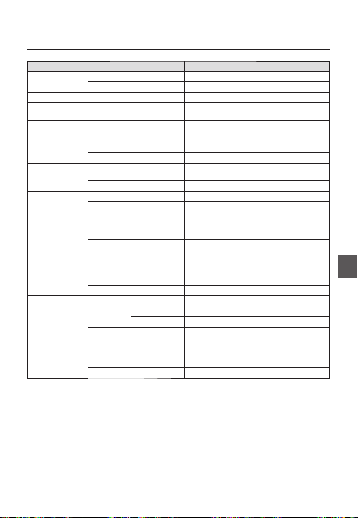
Технические характеристики
Пункты Подпункты SCC-B2333P / SCC-B2033P
Разрешение
Видеовыход
Соотношение
сигнал/шум
Объектив
Сигнал тревоги
Пульт ДУ
Условия
окружающей среды
Питание
Физические
характеристики
По горизонтали 600 телевизионных строк
По вертикали 350 телевизионных строк
- VBS 1.0Vp-p, 75 Ω
Соотношение сигнал/шум прибл. 52 дБ
Тип драйвера объектива РУЧНОЙ/AI(ВИДЕО/DC)
Тип крепления CS/C
Вход нет данных
Выход 1 выход
Коакситрон (передача данных через
коаксиальный кабель):
RS-485 Да (несколько протоколов, 8 шт.)
Рабочая температура -10˚C ~ +50˚C
Влажность менее 90%
Требуемое напряжение
Потребление электроэнергии
(с объективом DC)
Индикатор Да
Размеры
без упаковки
(ШxВxГ)
С упаковкой 173 (Ш) x 99 (В) x 115 (Г) мм
без упаковки
Вес
С упаковкой
Цвет Корпус серебристый
Да (с моделью SCX-RD100)
SCC-B2333P : 24 В переменного тока ± 10% (50 Гц ± 0,3 Гц)
12 В постоянного тока ± 10%
SCC-B2033P : 220 В переменного тока ± 10% (50 Гц ± 0,3 Гц)
В обычных условиях :
SCC-B2333P : 2,3 Вт
SCC-B2033P : 2,9 Вт
При переключении фильтра ДЕНЬ/НОЧЬ :
SCC-B2333P : 2,8 Вт
SCC-B2033P : 3,4 Вт
SCC-B2333P : 64 (Ш) x 58 (В) x 109,2 (Г) мм
SCC-B2033P : 64 (Ш) x 58 (В) x 129,2 (Г) мм
SCC-B2333P : прибл. 305 г
SCC-B2033P : прибл. 395 г
SCC-B2333P : прибл. 530 г
SCC-B2033P : прибл. 620 г
RUS
Pyccкий – 31

Правильная утилизация данного устройства
(Утилизация электрического и электронного оборудования)
(Действует во всех странах Европейского Союза и других странах Европы, принявших систему разделения
отходов)
Подобная маркировка на изделии, принадлежностях или в руководстве к нему предупреждает, что
по истечении срока службы изделие или электронные принадлежности для него (например, зарядное
устройство, наушники, кабель USB) не следует выбрасывать вместе с другим бытовым мусором. Чтобы
избежать вредного воздействия на окружающую среду или на здоровье человека от неконтролируемой
утилизации отходов, следует отделять маркированные подобным образом изделия от другого мусора для
соответствующей переработки и повторного использования в качестве сырья.
За подробной информацией о месте и способе экологически безопасной утилизации бытовым
потребителям следует обращаться к продавцу данного изделия или в органы местного самоуправления.
Промышленным потребителям необходимо обратиться к поставщику, чтобы уточнить сроки и условия
договора купли-продажи. Подобные изделия и электронные принадлежности не следует утилизировать
вместе с другими производственными отходами.

SCC-B2333(P)
SCC-B2033P
CYFROWA KAMERA
KOLOROWA
Podręcznik użytkownika
wyobraź sobie możliwości
Dziękujemy za zakup produktu fi rmy Samsung.
W celu uzyskania pełniejszej obsługi
zarejestruj swój produkt na stronie
www.samsungsecurity.com
POL

informacje dotyczące bezpieczeństwa
UWAGA
NIEBEZPIECZEŃSTWO PORAŻENIA PRĄDEM.
NIE OTWIERAĆ
UWAGA: ABY ZMNIEJSZYĆ RYZYKO PORAŻENIA PRĄDEM NIE USUWAĆ OBUDOWY (ANI CZĘŚCI TYLNEJ). NIE MA CZĘŚCI
PRZEZNACZONYCH DO NAPRAWY PRZEZ UŻYTKOWNIKA. NALEŻY SKONTAKTOWAĆ SIĘ Z WYKWALIFIKOWANYM
PERSONELEM SERWISU.
Ten symbol oznacza, że urządzenie pracuje pod wysokim napięciem, co może grozić
porażeniem prądem elektrycznym.
Ten symbol oznacza, że materiały dostarczone razem z urządzeniem zawierają ważne
instrukcje dotyczące obsługi i konserwacji urządzenia.
OSTRZEŻENIE
Aby zmniejszyć ryzyko pożaru lub porażenia prądem elektrycznym, nie należy wystawiać
•
urządzenia na działanie wody ani wilgoci.
OSTRZEŻENIE
Używaj tylko standardowego adaptera określonego w karcie charakterystyki technicznej.
1.
Stosowanie wszelkich innych adapterów może spowodować pożar, porażenie prądem lub
uszkodzić produkt.
Nieprawidłowe podłączenie zasilania lub wymiana baterii może spowodować wybuch, pożar,
2.
porażenie prądem lub uszkodzić produkt.
Nie należy podłączać kilku kamer do jednego adaptera. Przekroczenie dopuszczalnego limitu
3.
może spowodować nadmierną emisję ciepła lub pożar.
Przewód zasilający należy pewnie podłączyć do oprawy gniazda. Niepewne podłączenie może
4.
spowodować pożar.
Kamerę należy zamocować bezpiecznie i solidnie. Spadająca kamera może spowodować
5.
obrażenia ciała.
Na kamerze nie wolno ustawiać przedmiotów przewodzących prąd (np. śrubokrętów, monet,
6.
przedmiotów metalowych itp.) ani pojemników napełnionych wodą. W przeciwnym wypadku
może dojść do uszkodzenia ciała w wyniku pożaru, porażenia prądem lub upadku przedmiotów.
Urządzenia nie należy montować w miejscach wilgotnych, zakurzonych ani pokrytych sadzą. W
7.
przeciwnym razie może dojść do pożaru lub porażenia prądem.
Jeśli z urządzenia wydobywa się podejrzany zapach lub dym, należy zaprzestać jego używania.
8.
W takim przypadku należy natychmiast odłączyć zasilanie i skontaktować się z centrum
serwisowym.
Dalsza eksploatacja może w tym stanie doprowadzić do pożaru lub porażenia prądem.
2 – CYFROWA KAMERA KOLOROWA

informacje dotyczące bezpieczeństwaa
9.
Jeśli niniejszy produkt nie działa normalnie należy skontaktować się z najbliższym centrum
serwisowym. Niniejszego produktu nie wolno demontować ani modyfi kować w żaden sposób.
(SAMSUNG nie ponosi odpowiedzialności za problemy spowodowane przez samodzielne
modyfi kacje lub próby napraw).
10.
Podczas czyszczenia nie należy bezpośrednio spryskiwać wodą elementów produktu. W
przeciwnym razie może dojść do pożaru lub porażenia prądem.
UWAGA
Na produkt nie należy upuszczać przedmiotów ani powodować silnych wstrząsów. Produkt
1.
należy umieszczać w miejscach, gdzie nie ma nadmiernych wibracji ani pola magnetycznego.
Produktu nie należy montować w miejscach, gdzie panują wysokie (ponad 50°C) lub niskie
2.
(poniżej -10°C) temperatury, lub wysoka wilgotność. W przeciwnym razie może dojść do pożaru
lub porażenia prądem.
W celu przeniesienia zamontowanego produktu należy najpierw wyłączyć jego zasilanie a
3.
następnie przemieścić lub ponownie zamontować produkt.
W czasie burzy z wyładowaniami atmosferycznymi należy wyciągnąć wtyczkę z gniazda.
4.
Pozostawienie podłączonego zasilania może wywołać pożar lub uszkodzenie produktu.
Produkt należy trzymać poza zasięgiem promieni słonecznych oraz źródeł promieniowania
5.
cieplnego. Może to spowodować pożar.
Produkt należy montować w miejscu z dobrą wentylacją.
6.
Nie należy kierować kamery bezpośrednio na bardzo jasne obiekty jak np. słońce, gdyż może to
7.
uszkodzić czujnik obrazu CCD.
Urządzenie nie powinno być narażone na kapanie lub rozlanie płynu, nie należy na nim stawiać
8.
przedmiotów wypełnionych cieczą np. wazonów.
Wtyczka sieci zasilającej stosowana jest jako urządzenie rozłączające, dlatego powinna być łatwo
9.
dostępna przez cały czas.
POL
Polski – 3

Ważne zalecenia dotyczące bezpieczeństwa
Należy przeczytać poniższe zalecenia.
1.
Należy zachować je do wglądu.
2.
Należy przeczytać wszystkie ostrzeżenia.
3.
Należy przestrzegać wszystkich zaleceń.
4.
Nie używać urządzenia w pobliżu wody.
5.
Czyścić wyłącznie suchą szmatką.
6.
Nie blokować żadnych otworów wentylacyjnych. Montować zgodnie z instrukcją producenta.
7.
Nie montować w pobliżu źródeł ciepła takich jak grzejniki, kratki nagrzewnic lub innych urządzeń (w tym
8.
wzmacniaczy) emitujących ciepło.
Nie lekceważyć zabezpieczenia wynikającego ze stosowania wtyczek spolaryzowanych lub z uziemieniem.
9.
Wtyczka spolaryzowana ma dwa bolce, z których jeden jest szerszy od drugiego.
Wtyczka z uziemieniem ma trzy bolce, z czego jeden jest uziemiający.
Szerszy lub odpowiednio trzeci bolec stosuje się w celu zapewnienia bezpieczeństwa. Jeśli dostarczona
wtyczka nie pasuje do gniazda, skontaktuj się z elektrykiem w celu wymiany przestarzałego gniazda.
Przewód zasilający przy wtyczkach, oprawach oraz w miejscach, gdzie wystają one z urządzenia należy
10.
zabezpieczyć przed możliwością nadepnięcia lub przyciśnięcia.
Używać wyłącznie elementów dodatkowych/akcesoriów zalecanych przez producenta.
11.
Używać wyłącznie z wózkiem, stojakiem, trójnogiem lub stolikiem zalecanym przez
12.
producenta lub sprzedawanym wraz z urządzeniem.
Urządzenie należy odłączyć z sieci. Jeśli stosuje się wózek, należy zachować
13.
ostrożność przy przemieszczaniu zmontowanego wózka z urządzeniem, aby uniknąć
odniesienia obrażeń w przypadku przewrócenia.
Wszelkie naprawy należy zlecać wykwalifi kowanemu personelowi serwisu. Naprawy są konieczne gdy
14.
urządzenie zostało uszkodzone w jakikolwiek sposób, np. gdy uszkodzony jest przewód zasilający lub
wtyczka, do środka urządzenia przedostał się płyn lub ciała obce, urządzenie miało kontakt z deszczem lub
wilgocią, nie funkcjonuje normalnie lub spadło.
4 – CYFROWA KAMERA KOLOROWA

Spis treści
Wprowadzenie
Funkcje 6
Produkt i Akcesoria 7
Nazwy części i funkcje 8
Wprowadzenie
Podłączanie łącznika obiektywu Auto Iris(PRZYSLONA) 11
Montaż obiektywu 11
Podłączanie kabli i sprawdzanie działania 12
Jak korzystać z menu ekranowego
Używanie ikon w MENU 13
Menu główne 13
Profi l 14
Ustawienia kamery 16
Inteligencja 22
Konfi guracja strefy prywatności
Inne ustawienia 25
Komunikacja 26
Informacje o systemie 26
Jezyk 26
Dane techniczne
Dane techniczne 28
24
POL
Polski – 5

Wprowadzenie
FUNKCJE
Wysoka rozdzielczość
❖
Kamera oferuje wysoką rozdzielczość (600 linii) dzięki zastosowaniu najnowocześniejszych technologii
•
cyfrowego przetwarzania obrazu przy użyciu specjalnych algorytmów.
Inteligentne wykrywanie ruchu i śledzenie
❖
Jest to inteligentna funkcja umożliwiająca automatyczne wykrywanie ruchu obiektu. Można ustawić wirtualne
•
ogrodzenie, aby rozległ się alarm dźwiękowy, jeśli obiekt przekroczy/wejdzie/wyjdzie z wirtualnego ogrodzenia
lub wirtualnego obszaru.
XDR (Rozszerzony zakres dynamiczny — ang. eXtended Dynamic Range)
❖
Aktywnie steruje kompensacją gamma w taki sposób, że steruje kontrastem jasności otoczenia w danej
•
jednostce piksela, aby określić optymalną widoczność.
DZIEN/NOC
❖
Ta funkcja służy do wyłączania funkcji fi ltrowania promieni podczerwonych, kiedy wartość oświetlenia jest
•
niższa od normalnej.
Wysoka czułość
❖
Umożliwia wykonywanie obrazów wysokiej czułości z wykorzystaniem nowoczesnej technologii SONY Super-
•
HAD IT CCD.
Słabe oświetlenie
❖
Kamera wykorzystuje technologię cyfrowej obróbki sygnału, np. funkcje dla słabego oświetlenia lub funkcję
•
Dzien/Noc, dzięki którym urządzenie umożliwia identyfi kację obiektów nawet w najgorszych warunkach.
Bardzo dobra funkcja regulacji podświetlenia
❖
Kiedy za obiektem występuje źródło jasnego światła lub słońce, kamera automatycznie poprawia jakość
•
zacienionej części obrazu.
Cyfrowa synchronizacja
❖
W pełni cyfrowa funkcja synchronizacji linii bezpośrednio dostosowuje synchronizację pionową kamery, w
•
celu polepszenia działania kamery i jej niezawodności.
Ustawienia sygnału wyjściowego
❖
Można ustawić następujące opcje sygnału wyjściowego wideo: Odwrócenie obrazu (poziome, pionowe
•
lub oba), Prywatność, Profi lowanie poziome/pionowe i zoom cyfrowy.
Menu ekranowe
❖
Menu ekranowe służy do wyświetlania stanu kamery i interaktywnej konfi guracji funkcji.
•
Komunikacja przez przewód koncentryczny
❖
Jest to funkcja zdalnego sterowania polegająca na przesyłaniu sygnału sterowania przez przewód
•
koncentryczny (do przesyłania sygnału wideo). Podczas instalacji lub naprawy pomaga on sterować
sterownikiem komunikacji (opcjonalna) bez dodatkowych przewodów.
6 – CYFROWA KAMERA KOLOROWA

PRODUKT I AKCESORIA
Produkt i Akcesoria❖
Urządzenie główne
•
Akcesoria
•
Uchwyt kamery
(mocowanie)
Łącznik podstawy C
Wprowadzenie
Kamera
Podręcznik
użytkownika
Łącznik obiektywu
Auto Iris(przyslona)
POL
Polski – 7

Wprowadzenie
NAZWY CZĘŚCI I FUNKCJE
Widok z boku❖
Wgłębienia do
mocowania łącznika
Łącznik
obiektywu Auto
Iris(przyslona)
Przewód kontrolny
obiektywu Auto Iris
Łącznik obiektywu Auto Iris(przyslona)
•
To wgłębienie używane jest do przykręcania łącznika, części uchwytu, na którym mocowana jest kamera.
Przewód kontrolny obiektywu Auto Iris
•
Przewód przesyła zasilanie oraz sygnały z kamery w celu sterowania obiektywem Auto Iris.
Wgłębienia do mocowania łącznika
•
Te wgłębienia używane są przy przykręcaniu śrub do łącznika mocowanego do uchwytu oraz kamery.
Uwaga :
W przypadku zabrudzenia obiektywu należy go delikatnie przetrzeć chusteczką do soczewek lub szmatką nasączoną etanolem.
–
8 – CYFROWA KAMERA KOLOROWA
Obiektyw

Wprowadzenie
Panel tylny❖
<AC24/DC12V (SCC-B2333(P))>
n
p
r
<AC220V~240V(SCC-B2033P)>
n
s
o
q
s
POL
o
p
q
Polski – 9
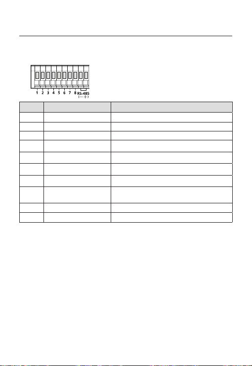
Wprowadzenie
n Złącza wejścia/wyjścia
To złącze posiada gniazda wejściowe i wyjściowe dla sygnałów sterowania RS-485, funkcji przełączania
pomiędzy trybami DZIEN/NOC oraz sygnałów wyjściowych alarmu.
Nr. Funkcja Opis
1 ALARM OUT
2 GND Gniazdo uziemienia.
3 GND Gniazdo uziemienia.
4 SHUTTER (S0)
5 SHUTTER (S1)
6 SHUTTER (S2)
7 5V OUT
8
9 RS-485 DATA-
10 RS-485 DATA+
o Przełącznik konfi guracji
Ten przełącznik służy do ustawiania funkcji lub właściwości. Naciśnięcie tego przycisku i przytrzymanie przez
co najmniej 2 sekundy powoduje wyświetlenie menu MAIN MENU (MENU GLOWNE).
ef
Ruch [W lewo/W prawo] lub zmiana wyświetlanej wartości: Naciskanie tego przełącznika w lewo lub
w prawo powoduje ruch w odpowiednim kierunku lub zmianę wyświetlanej wartości.
cd
Ruch [W górę/W dół]: Naciskanie tego przełącznika w górę lub w dół powoduje przechodzenie w górę lub w dół menu.
: Naciśnięcie przycisku w menu powoduje potwierdzenie zaznaczonej funkcji. Naciśnij ten przycisk, aby
przejść do menu podrzędnego.
p Wskaźnik LED zasilania
Czerwona dioda LED świeci, kiedy zasilanie jest normalnie podłączone.
q Gniazdo Video OUT
Łączy się je z gniazdem wejścia wideo monitora; stanowi ono wyjście sygnałów wideo.
r GND
Jest to port uziemiający
s Gniazdo zasilania
Służy do podłączania kabla zasilania.
DAY/NIGHT IN
10 – CYFROWA KAMERA KOLOROWA
Gniazdo wyjścia alarmu wykrywania ruchu. (Typ Open collector)
Jest to port służący do wybierania zewnętrznego trybu dużej szybkości migawki.
Jeżeli zostanie podłączony do NISKI (0 V), wewnątrz zostanie ustawiony na WŁ.
Jest to port służący do wybierania zewnętrznego trybu dużej szybkości migawki.
Jeżeli zostanie podłączony do NISKI (0 V), wewnątrz zostanie ustawiony na WŁ.
Jest to port służący do wybierania zewnętrznego trybu dużej szybkości migawki.
Jeżeli zostanie podłączony do NISKI (0 V), wewnątrz zostanie ustawiony na WŁ.
Gniazdo zasilania dla RS-485 JIG. Stosować typowe zasilanie prądem stałym w
przedziale +5 V 100 mA
Jest to gniazdo służące do konwersji DAY/NIGHT (DZIEN/NOC).
Wysoka (prąd stały +3 V~+5 V): Tryb DAY(COLOR) (DZIEN(KOLOR)) Tryb
NIGHT (WB) (NOC(C/B))
Jest to gniazdo do podłączania linii sygnału danych DATA- urządzenia RS-485.
Jest to gniazdo do podłączania linii sygnału danych DATA+ urządzenia RS-485.

PODŁĄCZANIE ŁĄCZNIKA OBIEKTYWU
AUTO IRIS(PRZYSLONA)
Podłącz każdy z nieosłoniętych kabli sterowania
migawką do łącznika obiektywu Auto Iris(przyslona)
w następujący sposób
Typ
Nr
sterowania
styku
1 Tłumienie (-) Zasilanie (+12 V)
2 Tłumienie (+) Nie dotyczy
3 Napęd (+) Sygnał wideo
4 Napęd (-) Uziemienie
Uwaga :
W menu można przełączyć typ sterowania obiektywem.
–
DC
Typ sterowania
wideo
MONTAŻ OBIEKTYWU
W przypadku stosowania obiektywu CS
Obiektyw należy zamontować, obracając go w
kierunku ruchu wskazówek zegara w sposób
przedstawiony na ilustracji:
W przypadku stosowania obiektywu C
Po zamontowaniu podstawki C, obracając ją w
kierunku ruchu wskazówek zegara, należy wkręcić
obiektyw C w kierunku ruchu wskazówek zegara, aż
zostanie zamocowany, w sposób przedstawiony
na ilustracji:
Wprowadzenie
Obiektyw CS
CS 렌즈
Obiektyw C
C 렌즈
POL
Polski – 11

Wprowadzenie
PODŁĄCZANIE KABLI I
SPRAWDZANIE DZIAŁANIA
①
Podłącz jeden z końców przewodu BNC do
portu VIDEO OUT znajdującego się z tyłu
kamery.
② Podłącz drugi koniec przewodu BNC do
portu VIDEO IN znajdującego się w monitorze.
Złącze wejścia wideo tylnego
panelu monitora
Kabel BNC
1
.
A
L
A
R
2
.
A
G
M
N
O
D
3
U
.
T
G
N
5
.
D
S
4
.
H
S
U
H
6
T
U
.
T
S
T
E
T
H
R
E
U
(
S
R
7
T
1
(
.
T
S
)
5
E
O
V
R
)
(
O
S
8
U
2
.
)
T
D
A
Y
/
N
I
G
H
T
I
N
1
2
3
4
5
6
7
8
③
Następnie podłącz zasilacz do kamery. Do
kamery można podłączyć 2 linie z zasilacza za
pomocą wkrętaka w sposób przedstawiony na
ilustracji. (GND: kabel z białym paskiem)
1
.
A
L
A
R
2
.
A
G
M
N
O
D
3
U
.
T
G
N
5
.
D
S
4
.
H
S
U
H
6
T
U
.
T
S
T
E
T
H
R
E
U
(S
R
7
T
1
(
.
T
S
)
5
E
O
V
R
)
(S
O
8
U
2
.
)
T
D
A
Y
/
N
I
G
H
T
I
N
1 2
3 4 5
6
7 8
Złącze wyjścia wideo
12 – CYFROWA KAMERA KOLOROWA
Uwaga :
Można podłączyć dowolne źródło zasilania prądem
–
zmiennym 24 V i prądem stałym 12 V, nie zważając na
biegunowość.

Jak korzystać z menu ekranowego
UŻYWANIE IKON W MENU
(ZAKONCZ)
•
Zamyka ustawienie menu.
Przed zakończeniem menu, wybierz opcję ZAPISZ,
aby zapisać wprowadzone ustawienia, lub
WYJSCIE, aby anulować.
(POWROT)
•
Powoduje powrót do poprzedniego menu.
(HOME)
•
Powraca do menu głównego.
(ZAPISZ)
•
Służy do zapisywania ustawień opcji OBSZAR
MASKI, STREFA PRYW. i innych.
Po zapisaniu ustawień zostaną one zastosowane
nawet w przypadku wybrania opcji WYJSCIE w
menu.
(USUN)
•
Służy do usuwania ustawień opcji OBSZAR
MASKI, STREFA PRYW. i innych.
Po usunięciu ustawień nie zostaną one
przywrócone nawet w przypadku wybrania opcji
WYJSCIE w menu.
MENU GŁÓWNE
ÃÃMENU GLOWNEÃÃ
PROFIL
UST. KAMERY
INTELIGENCJA
STREFA PRYW.
INNE USTAWIENIA
KOMUNIKACJA
INFO O SYSTEMIE
JEZYK
PROFIL
•
Można ustawić tryb dostosowany do warunków
instalacji kamery.
UST. KAMERY
•
Konfi guracja funkcji i danych związanych z
kamerą.
INTELIGENCJA
•
Można skonfi gurować ustawienia wykrywania
ruchu, śledzenia i inne.
STREFA PRYW.
•
Można skonfi gurować ustawienia związane z
prywatnością.
•
INNE USTAWIENIA
Można skonfi gurować między innymi opcję
Factory Defaults (Domyslne ust. fab.)..
•
KOMUNIKACJA
Konfi guruje ustawienia dotyczące komunikacji
przez interfejs RS-485.
•
INFO O SYSTEMIE
Wyświetla informacje o systemie, w tym wersję
kamery oraz ustawienia komunikacji.
•
JEZYK
Wybierz preferowaną opcję spośród
obsługiwanych języków.
POL
Polski – 13
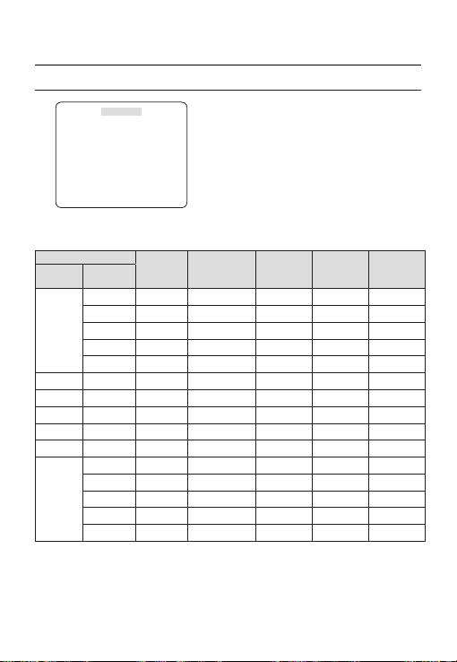
Jak korzystać z menu ekranowego
PROFIL
e
PROFIL
f
STANDARD.
Ã
ITS
PODŚWIETL.
DZIEN/NOC
GRANIE
WLASNY
W menu PROFIL można skonfi gurować jednocześnie następujące ustawienia kamery.
Menu UST.KAMERY
Poprzednie
menu
PRZYSLONA
ALC - - - - -
DET. RUCH (
DNR MID MID MID MID MID
MIGAWKA WYL. AUTO1/250 WYL. WYL. WYL.
CZULOSC AUTOx4 AUTOx2 AUTOx4 AUTOx4 AUTOx4
XDR MID MID MID MID MID
DZIEN/NOC AUTO AUTO DZIEN AUTO DZIEN
NOC - - - - -
ZEWNETRZNY - - - - -
STANDARD. ITS PODŚWIETL. DZIEN/NOC GRANIE
Menu
podrzędne
OBIEKTYW OB. DC OB. DC OB. DC OB. DC OB. DC
PODŚWIETL. WYL. WYL. BLC WYL. WYL.
ALC ALC ALC ALC ALC
POZIOM 0 0 0 0 0
B.SZYBKO
)--- (B.SZYBKO)--- NORMALNIE (B.SZYBKO)--- WOLNO
BURST WYL. WL. WYL. WYL. WYL.
BURST WYL. WL. WYL. WYL. WYL.
14 – CYFROWA KAMERA KOLOROWA

Jak korzystać z menu ekranowego
Menu UST.KAMERY
Poprzednie
menu
BALANS BIELI
DZIEN - - - - -
NOC - - - - -
DETAL 2 2 2 2 2
ITS
❖
STANDARD. ITS PODŚWIETL. DZIEN/NOC GRANIE
Menu
podrzędne
CZERWONY 0 0 0 0 0
CZERWONY
DZIEN DZIEN/NOC DZIEN DZIEN/NOC DZIEN
MODE ATW2 ATW1 ATW1 ATW1 ATW1
NIEBIESKI 0 0 0 0 0
Możliwe jest
wprowadzanie
JASNOSC
ustawień
użytkownika
MODE WYL. ATW2 WYL. ATW2 WYL.
Możliwe jest
wprowadzanie
ustawień
użytkownika
Możliwe jest
wprowadzanie
NIEBIESKI
ustawień
użytkownika
Możliwe jest
wprowadzanie
MID
ustawień
użytkownika
Możliwe jest
wprowadzanie
0
ustawień
użytkownika
Możliwe jest
wprowadzanie
0
ustawień
użytkownika
Możliwe jest
wprowadzanie
MID
użytkownika
Możliwe jest
wprowadzanie
0
użytkownika
Możliwe jest
wprowadzanie
0
użytkownika
ustawień
ustawień
ustawień
Ustawienie zostanie wprowadzone automatycznie, aby można było łatwo sprawdzić warunki drogowe.
PODŚWIETL.
❖
Ustawienie zostanie wprowadzone automatycznie, aby można było odróżnić obiekt od tła w warunkach silnego
podświetlenia od tyłu.
DZIEN/NOC
❖
Funkcja zostanie ustawiona automatycznie w celu optymalizacji do warunków dziennych lub nocnych.
GRANIE
❖
Opcja zostanie ustawiona automatycznie, aby ułatwić wykonanie zdjęcia w warunkach zwykłego oświetlenia
wewnątrz.
POL
Polski – 15

Jak korzystać z menu ekranowego
ID KAMERY [WYL., WL.]
USTAWIENIA KAMERY
eUST. KAMERYf
ID KAMERY WYL.
PRZYSLONA ALC
DET. RUCH (B.SZYBKO)--DNR MID
MIGAWKA WYL.
CZULOSC AUTO X4
KOMP. MIGOTANIA(WYL.)--XDR MID
DZIEN/NOC AUTO
BALANS BIELI
ZOOM CYFROWY
DETAL [2]
SYN.-PION INT
AGC KOLOR SUP
ODWROC WYL.
POSI/NEGA +
PIP WYL.
DIS WYL.
Konfi guruje ogólne funkcje modułu zoomu kamery.
Aby zaznaczyć pozycję menu, użyj przycisku
cdef
16 – CYFROWA KAMERA KOLOROWA
d
c
WYL.
NISKI
d
c
.
❖
ID KAMERY
ABCDEFGHIJKLMNOPQRSTUVWXYZ0
123456789 :?-+*()/
SP
ffee
SP LOKALIZACJA
KAMERY-1..................
...........................
Menu ID KAMERY służy do przypisywania
kamerze niepowtarzalnej nazwy. Naciśnięcie
przycisku SETUP, gdy wybrane jest menu
ID KAMERY spowoduje wyświetlenie
odpowiedniego ekranu.
Dla ustawienia ID KAMERY można wprowadzić
do 54 znaków alfanumerycznych lub specjalnych.
Wybierz opcję LOKALIZACJA i naciśnij przycisk
SETUP, aby przenieść pozycję wyświetlania
danych ID KAMERY.
❖
PRZYSLONA [ALC, KONT. ELC]
Menu PRZYSLONA służy do regulowania natężenia
promieniowania wchodzącego do kamery.
•
ALC (automatyczne sterowanie oświetleniem
— Automatic Light Controll)
① Naciśnięcie przycisku SETUP, gdy wybrane
jest menu podrzędne ALC spowoduje
wyświetlenie odpowiedniego ekranu.
ALC
OBIEKTYW OB. DC
POZIOM [00]----I---PODŚWIETL. WYL.
Menu OBIEKTYW służy do wybierania typu
obiektywu AI.
Aby kamera działała normalnie, należy wybrać
opcję OB. DC dla obiektywu typu DC oraz
OB.VIDEO dla obiektywu typu VIDEO.

Jak korzystać z menu ekranowego
Menu POZIOM służy do regulacji ogólnej
jasności, przy czym „+” zwiększa jasność, a „-”
ją zmniejsza.
② Jeśli opcja PODŚWIETL. jest ustawiona na
BLC, zostanie wyświetlone menu, w którym
można ustawić obszar BLC.
Wybraną strefę BLC można ustawić defi niując
jej rozmiar i lokalizację.
ALC
OBIEKTYW OB. DC
POZIOM [00]----I---PODŚWIETL. BLC
OBSZAR UZYTKOWNIK
<ROZM.>
<LOKALIZACJA>
Jeżeli zwykła kamera jest używana do
fi lmowania sceny intensywnie oświetlonej od
tyłu, obiekt będzie wyświetlany na monitorze
jako czarny z powodu podświetlenia od tyłu. Aby
rozwiązać ten problem można użyć funkcji BLC
(ang. Back Light Compensation), aby poprawić
ostrość obrazu z tak silnym kontrastem.
KONT. ELC (elektroniczne sterowanie
•
oświetleniem))
①
Naciśnięcie przycisku SETUP, gdy wybrane
jest menu podrzędne KONT. ELC powoduje
wyświetlenie odpowiedniego ekranu. Funkcję
KONT. ELC można włączyć lub wyłączyć.
KONT. ELC
POZIOM [00]----I---PODŚWIETL. WYL.
② W podobnym ustawieniu do ALC można
określić obszar BLC.
KONT. ELC
POZIOM [00]----I---PODŚWIETL. BLC
OBSZAR UZYTKOWNIK
<ROZM.>
<LOKALIZACJA>
AGC
[WYL., BARDZO NIS., NISKI, MID, WYSOKI,
❖
BARDZO WYS., UZYTKOWNIK, FIX]
Menu AGC (ang. Auto Gain Control) służy
do ustawiania poziomu funkcji AGC kamery.
Gdy funkcja AGC jest aktywna, kamera
automatycznie zwiększa czułość wzmacniając
sygnał wideo, gdy siła sygnału spada poniżej
normalnego poziomu.
Jeśli w menu CZULOSC wybrana jest opcja WYL.
lub tryb FIX, można określić poziom AGC.
Naciśnięcie przycisku SETUP, gdy wybrane jest
menu podrzędne UZYTKOWNIK spowoduje
wyświetlenie odpowiedniego ekranu.
AGC UZYTKOWNIK
POZIOM [16]
W trybie UZYTKOWNIK można podzielić poziom
na 16 kroków od BARDZO NIS. do BARDZO
WYS. zgodnie z własnymi preferencjami.
POL
Polski – 17

Jak korzystać z menu ekranowego
MIGAWKA
AGC FIX
POZIOM [01]
Naciśnięcie przycisku SETUP, gdy wybrane jest
menu podrzędne FIX spowoduje wyświetlenie
odpowiedniego ekranu.
Ze względu na to, że w trybie FIX używana jest stała
wartość wzmocnienia ACG, przed ustaleniem tej
wartości można wybrać jeden z 16 szczegółowych
poziomów od BARDZO NIS. do BARDZO WYS.
Uwaga :
Jeśli menu DZIEN/NOC funkcji UST. KAMERY jest
–
ustawione na AUTO, menu AGC jest nieaktywne.
W przypadku ustawienia opcji KOMP. MIGOTANIA na
–
WL., opcja AGC FIX jest nieaktywna.
❖
DET. RUCH
[B.WOLNO, WOLNO, NORMALNIE, SZYBKO, B.SZYBKO]
Menu RUCH służy do regulacji natężenia poziomu
AGC w celu sterowania ruchem kamery. Ta opcja
dostępna jest tylko, gdy menu CZULOSC jest
ustawiona na AUTO.
Poziom AGC można wybrać spośród opcji B.WOLNO,
WOLNO, NORMALNIE, SZYBKO i B.SZYBKO.
Jeżeli obserwowany jest szybko poruszający
się obiekt w mało kontrastowej scenerii, wybierz
opcję B.SZYBKO, natomiast w przypadku obiektu
poruszającego się z bardzo małą prędkością w tej
samej scenerii wybierz opcję B.WOLNO.
Uwaga :
Jeśli menu DZIEN/NOC funkcji UST.KAMERY jest
–
ustawione na AUTO, menu DET. RUCH jest nieaktywne.
DNR
[WYL.,NISKI,MID,WYSOKI, UZYTKOWNIK(1~16)]
❖
Można skonfi gurować ustawienia związane z
funkcją DNR (cyfrowa redukcja szumów — ang.
Digital Noise Reduction).
Zmniejsza szumy na ekranie.
Jest to szczególnie przydatna funkcja w przypadku
mocno zniekształconego ekranu.
Jeśli funkcja DNR zostanie ustawiona na UZYTKOWNIKA,
możliwe będzie ustawienie poziomu.
18 – CYFROWA KAMERA KOLOROWA
❖
[WYL., AUTO 1/100(PAL:1/120), AUTO 1/250,
AUTO 1/500, AUTO 1/1000, AUTO 1/2000,
AUTO 1/4000, AUTO 1/10K , 1/100(PAL:1/120),
1/250, 1/500, 1/1000, 1/2000, 1/4000, 1/10K ,
ZEWNETRZNY]
Menu MIGAWKA służy do ustawiania stałej dużej
szybkości elektronicznej migawki, automatycznej
dużej szybkości elektronicznej migawki oraz
zewnętrznej dużej szybkości elektronicznej
migawki (ZEWNETRZNY).
Można wybrać jedną z 7 opcji od 1/100(PAL:1/120)
do 1/10 tys. w przypadku stałej dużej szybkości
elektronicznej migawki, która jest najczęściej używana
do robienia zdjęć szybko poruszających się obiektów.
Automatyczna duża prędkość elektronicznej
migawki działa w taki sposób jak stała duża
prędkość elektronicznej migawki w scenerii o
wysokim kontraście, ale automatycznie wyostrza
cel, jeżeli przysłona zostanie całkowicie otwarta w
scenerii o niskim kontraście, na przykład w trybie
KONT. ELC. Gdy sceneria ponownie się rozjaśni,
nastąpi przełączenie w tryb stałej dużej prędkości
elektronicznej migawki.
Jednak tryb automatycznej dużej prędkości
migawki działa prawidłowo tylko, gdy kamera jest
wyposażona w obiektyw OB. DC lub OB. VIDEO.
W trybie zewnętrznej dużej prędkości
elektronicznej migawki (ZEWNETRZNY) można
wybrać jeden z 8 trybów od WYL. poprzez 1/100
(PAL:1/120) do 1/10 tys. dla dużej prędkości
elektronicznej migawki. Działa to w taki sposób,
jak duża prędkość elektronicznej migawki. Można
wybrać opcję za pomocą opcji SHUTTER(S0),
SHUTTER(S1) i SHUTTER(S2) z tyłu.
Podłącz wszystkie złącza do uziemienia
oznaczonego skrótem GND.
W poniższej tabeli znajdują się informacje
dotyczące działania.
SHUTTER
SHUTTER
(S0)
WYL.
WYL. WYL. WYL.
(NTSC: 1/60,
PAL:1/50)
1/100
WL. WYL. WYL.
(PAL:1/120)
1/250 WYL. WL. WYL.
SHUTTER
(S1)
(S2)

Jak korzystać z menu ekranowego
KOMP. MIGOTANIA [WYL., WL.]
1/500 WL. WL. WYL.
1/1000 WYL. WYL. WL.
1/2000 WL. WYL. WL.
1/4000 WYL. WL. WL.
1/10K WL. WL. WL.
Uwaga :
Jeżeli tryb PRZYSLONA jest ustawiony na KONT. ELC,
–
menu MIGAWKA będzie wyłączone, gdyż jasność będzie
regulowana za pomocą migawki elektronicznej.
Jeżeli funkcja CZULOSC jest ustawiona na AUTO, w memu
–
MIGAWKA dostępne są tylko pozycje WYL. i AUTO.
–
Jeżeli tryb CZULOSC jest ustawiony na FIX, menu
MIGAWKA będzie nieaktywne.
–
Jeżeli tryb KOMP. MIGOTANIA jest ustawiony na WL., menu
MIGAWKA będzie nieaktywne.
CZULOSC
❖
[WYL., AUTO X2, AUTO X4, AUTO X6, AUTO
X8, AUTO X12, AUTO X16, AUTO X24, AUTO
X32, AUTO X48, AUTO X64, AUTO X96, AUTO
X128, AUTO X256, AUTO X512, FIX X2, FIX
X4, FIX X6, FIX X8, FIX X12, FIX X16, FIX X24,
FIX X32, FIX X48, FIX X64, FIX X96, FIX X128,
FIX X256, FIX X512]
Automatycznie wykrywa poziom ciemności w
ciemnej lub mało kontrastującej scenerii, aby
wydłużyć skumulowany czas, zachowując
jasność i ostrość obrazu; opcji tej można używać
w trybie FIX.
Uwaga :
Jeżeli opcja MIGAWKA jest ustawiona na stałą migawkę
–
elektroniczną lub tryb ZEWNETRZNY, menu CZULOSC
będzie nieaktywne.
W przypadku ustawienia opcji KOMP. MIGOTANIA na
–
WL., tryb FIX menu CZULOSC jest nieaktywny.
Jeżeli menu PRZYSLONA jest ustawione na KONT. ELC,
–
elektroniczna migawka będzie sterować jasnością, więc
funkcja CZULOSC nie może zostać ustawiona na tryb FIX,
tylko na WYL. lub AUTO.
–
Jeżeli menu MIGAWKA jest ustawione na AUTO, menu
CZULOSC może zostać ustawione na WYL. lub w tryb AUTO.
❖
Jeżeli funkcja zostanie ustawiona na WL., szybkość
migawki zostanie ustawiona na 1/100(PAL: 1/120) sekund.
Zapobiegnie to ewentualnemu zniekształceniu ekranu
z powodu niedopasowania pomiędzy częstotliwością
synchronizacji pionowej i częstotliwością migotania
oświetlenia.
Uwaga :
Jeżeli funkcja PRZYSLONA jest ustawiona na KONT. ELC,
–
menu KOMP. MIGOTANIA będzie nieaktywne. Jeżeli menu
MIGAWKA jest ustawione na tryb AUTO, FIX lub
ZEWNETRZNY, menu KOMP. MIGOTANIA będzie nieaktywne.
Jeżeli funkcja CZULOSC jest ustawiona na FIX, menu
–
KOMP. MIGOTANIA będzie nieaktywne.
W przypadku ustawienia opcji AGC w tryb FIX, opcja
–
KOMP. MIGOTANIA jest nieaktywna.
XDR (eXtended Dynamic Range)
❖
[WYL., NISKI, MID, WYSOKI]
Aktywnie steruje kompensacją gamma ustawiając
kontrast jasności otoczenia w danej jednostce
piksela, aby określić optymalną widoczność.
Wybierz jedną z opcji WYL., NISKI, MID i
WYSOKI. Wybranie opcji WYSOKI spowoduje
zwiększenie poziomu kompensacji.
❖
DZIEN/NOC
•
DZIEN
Jeżeli zostanie ustawiona opcja DZIEN, funkcja
będzie ustawiona w tryb DZIEN niezależnie od
warunków otoczenia.
❖
NOC
Jeżeli zostanie ustawiona opcja
będzie ustawiona w tryb czarno-biały niezależnie od
warunków otoczenia.
Naciśnięcie przycisku SETUP po wybraniu menu
NOC spowoduje wyświetlenie menu, w którym
można ustawić funkcję Burst na WL./WYL..
Jeżeli funkcja BURST jest ustawiona na WL., sygnał
funkcji będzie wysyłany razem z kompozytowym
czarno-białym sygnałem wideo. Jeżeli funkcja BURST
jest ustawiona na WYL., sygnał tej funkcji nie jest
wysyłany.
Opcję BURST można ustawić na WL./WYL., lub
zaznaczyć sygnał wyjściowy Burst w trybie NOC.
[DZIEN,NOC,AUTO,ZEWNETRZNY]
NOC
, funkcja
POL
Polski – 19

Jak korzystać z menu ekranowego
AUTO
•
Kamera automatycznie będzie przełączać tryby
DZIEN i NOC, w zależności od warunków
oświetlenia.
Naciśnięcie przycisku SETUP, gdy wybrane jest
menu podrzędne AUTO spowoduje wyświetlenie
odpowiedniego ekranu.
Opcję BURST można ustawić na WL./WYL., lub
zaznaczyć sygnał wyjściowy Burst w trybie NOC.
Jasność dla trybu DZIEN -> NOC można wybrać
spośród opcji NISKI, MID i WYSOKI, które wskazują
poziom jasności podczas przełączania z fi ltra koloru
na czarno-biały. Przełączenie z opcji NISKI na
WYSOKI spowoduje włączenie fi ltra w scenerii o
niskim kontraście.Opcja CZAS WYŚWIET. funkcji
DZIEN->NOC, to czas wymagany na określenie
zapotrzebowania na przełączenie fi ltra.
Jasność dla trybu NOC -> DZIEN można wybrać
spośród opcji NISKI, MID i WYSOKI, które wskazują
poziom jasności podczas przełączania z fi ltra czarnobiałego na kolor. Przełączenie z opcji NISKI na
WYSOKI spowoduje włączenie fi ltra w scenerii o
niskim kontraście.Opcja CZAS WYŚWIET. funkcji
NOC->DZIEN, to czas wymagany na określenie
zapotrzebowania na przełączenie fi ltra.
Menu MASKI ma na celu zapobieganie występowaniu
błędu przełączenia fi ltra lub niemożności określenia
przełączenia w przypadku występowania źródła silnego
światła punktowego w nocy.
Naciśnięcie przycisku SETUP w pozycji 1 lub 2
menu MASKI spowoduje wyświetlenie menu, w
którym można określić obszar maski.
AUTO
BURST WYL.
DZIENÆNOC
JASNOSC MID
CZAS WYŚWIET. 2S
NOCÆDZIEN
JASNOSC MID
CZAS WYŚWIET. 5S
OBSZAR MASKI 1 2
OBSZAR MASKI
<ROZM.>
<LOKALIZACJA>
Można jednocześnie określić Maskę 1 i 2. Maska
służy tylko do określania przełączenia fi ltra
— wszelkie nadmiernie jasne obszary w nocnej
scenerii będą maskowane.
Uwaga :
Jeżeli funkcja PODŚWIETL. jest ustawiona na BLC, funkcja
–
OBSZAR MASKI będzie nieaktywna..
ZEWNETRZNY
•
Umożliwia to automatyczne przełączanie pomiędzy
DZIEN
i
NOC
trybem
zewnętrznym czujnikiem.
BALANS BIELI [DZIEN/NOC]
❖
Aby dostosować schemat kolorów, należy użyć
funkcji BALANS BIELI.
DZIEN
•
W trybie DZIEN można ustawić wartości
kolorów CZERWONY i NIEBIESKI. Ekran
zostanie wyświetlony w kolorach zgodnych z
wprowadzonymi ustawieniami.
Uwaga :
W trybie AWC można ustawić wartości WZM.-C i WZM.-
–
N.
z wykorzystaniem interfejsu z
BALANS BIELI
DZIEN/NOC DZIEN
MODE AWC
CZERWONY [00]----I--- NIEBIESKI [00]----I--- WZM.-C [0248]
WZM.-N. [0247]
20 – CYFROWA KAMERA KOLOROWA

Jak korzystać z menu ekranowego
NOC
•
Użyj trybu NOC, aby ustawić inny balans bieli
zgodny z jasnością otoczenia.
Jeśli tryb NOC jest ustawiony na WYL., balans
bieli zawsze działa w trybie DZIEN; jeśli nie jest
ustawiona opcja WYL., kamera przełączy się w
tryb DZIEN/NOC w zależności od jasności..
W trybie NOC można ustawić wartości kolorów
CZERWONY, NIEBIESKI i JASNOSC. Ekran
zostanie wyświetlony w kolorach zgodnych z
wprowadzonymi ustawieniami.
BALANS BIELI
DZIEN/NOC NOC
JASNOSC MID
MODE AWC
CZERWONY [00]----I--- NIEBIESKI [00]----I--- WZM.-C [0248]
WZM.-N. [0247]
Uwaga :
W trybie AWC można ustawić wartości WZM.-C i WZM.-
–
N.
Jeżeli funkcja AGC jest ustawiona na WYL. lub FIX, nie
–
można przejść do menu NOC.
Aby dostosować balans bieli dostępnych jest
–
5 następujących trybów:
ATW1(Tryb 1 automatycznego śledzenia
•
balansu bieli): Kamera automatycznie dostraja
temperaturę koloru w czasie rzeczywistym,
zgodnie z warunkami otoczenia. Temperatura
koloru ma zakres od ok. 2500 K do 9300 K.
ATW2: Temperatura koloru ma zakres od ok.
•
2000 K do 10000 K.
AWC (Automatyczne sterowanie balansem
•
bieli):Naciśnięcie przycisku SETUP po
ustawieniu kursora na odpowiedniej pozycji
spowoduje jednorazowe uruchomienie
Automatycznego balansu bieli.
3200K : Ustawia temperaturę koloru na 3200K
•
5600K : Ustawia temperaturę koloru na 5600K
•
CZERWONY : Reguluje intensywność czerwieni.
–
NIEBIESKI : Reguluje intensywność koloru
–
niebieskiego.
–
WZM.-C/WZM.-N : Umożliwia ustawienie ręczne
bieżącej temperatury koloru.
–
JASNOSC : Wybiera poziom jasności podczas
przełączania z ustawień trybu DZIEN na
ustawienia trybu NOC.
❖
ZOOM CYFROWY [WL./WYL.]
Można ustawić współczynnik i położenie zoomu
cyfrowego. Naciśnięcie przycisku SETUP, gdy
funkcja ZOOM CYFROWY jest ustawiona na
WL., zostanie wyświetlony określony ekran.
Gdy współczynnik i pozycja zoomu są
zdefi niowane, działać będzie funkcja zoomu
cyfrowego.
ZOOM CYFROWY
WSPOLCZYNNIK [X1.0]
< LOKALIZACJA >
-
LOKALIZACJA : Naciśnięcie przycisku SETUP w
sytuacji, gdy obraz jest powiększony w stopniu zgodnym
z ustawieniem współczynnika, można obserwować
niewidoczny obszar danego ekranu również za pomocą
przycisku
cdef
Uwaga :
Jeżeli współczynnik zoomu cyfrowego jest ustawiony na większy
–
niż 1x, funkcja FENCE będzie nieaktywna.
Funkcja ZOOM CYFROWY powiększa sam piksel, co może
spowodować pogorszenie jakości.
DETAL [0~3]
❖
.
Steruje wyróżnieniem poziomym lub pionowym.
Polski – 21
POL

Jak korzystać z menu ekranowego
SYN.-PION [INT, SYN ZEW.]
❖
Wybierz tryb synchronizacji pionowej INT lub SYN
ZEW..
Jeżeli wybrana zostanie opcja INT, kamera użyje
synchronizacji wewnętrznej.
Wybranie opcji SYN ZEW. spowoduje użycie
przez kamerę częstotliwości zewnętrznego źródła
zasilania do synchronizacji.
Można dostosować opcję FAZA SYN.
Uwaga :
Stosowanie zasilania prądem stałym 12 V spowoduje
–
trwałe ustawienie opcji SYN.-PION na INT, którego nie
można zmienić.
AGC KOLOR SUP [NISKI , MID, WYSOKI]
❖
Dostosuj schemat kolorów do wartości AGC.
ODWROC [WYL., H, V, H/V]
❖
Odzwierciedla sygnały wideo w poziomie, w
pionie lub w obydwu kierunkach.
POSI/NEGA [+, -]
❖
Wyjście w takiej postaci, w jakiej jest lub lustrzany
sygnał jasności wideo.
PIP [WYL., WL.]
❖
Wyświetla obraz podrzędny wraz z obrazem
głównym na tym samym ekranie za pomocą
funkcji Picture In Picture (obraz w obrazie).
Uwaga :
Jeżeli ustawiona jest więcej niż jedna strefa prywatności,
–
a funkcja PRIVACY SET jest ustawiona na WL., funkcja
PIP będzie nieaktywna.
Jeżeli funkcja INTELIGENCJA jest ustawiona na FENCE,
–
menu PIP będzie nieaktywne.
DIS [WYL., WL.]
❖
Cyfrowa stabilizacja obrazu uruchomi kompensację
przeciwwstrząsową.
Uwaga :
Jeżeli funkcja DIS jest ustawiona na WL., obszar
–
kompensacji zostanie powiększony zgodnie z
ustawieniem współczynnika zoomu cyfrowego.
Jeżeli współczynnik zoomu cyfrowego zostanie ustawiony
na wyższy niż współczynnik zoomu powiększonego
obszaru kompensacji, funkcja DIS jest nieaktywna..
22 – CYFROWA KAMERA KOLOROWA
INTELIGENCJA
eINTELIGENCJAf
DET. RUCH WYL.
ADVANCED WYL.
OBSZAR MASKI
WYSWIETL. WL.
CZULOSC [4]
ROZDZIELCZOSC [5]
WYJ.ALARMOWE
W menu INTELIGENCJA można ustawić detekcję
ruchu oraz śledzenie.
DET. RUCH [WYL.,ŚLEDZ.,DETEKCJA]
❖
•
ŚLEDZ.
Wykrywa i śledzi poruszający się obiekt.
•
DETEKCJA
Wykrywa ruchomy obiekt.
Uwaga :
Jeżeli opcja ta zostanie ustawiona na DETEKCJA, nie można
–
ustawiać takich funkcji jak FIXED/MOVED oraz FENCE w menu
ADVANCED.
ADVANCED
❖
Wykrywa ruch obiektu i wyświetla obraz
wszelkich poruszających się obiektów zanim
nastąpi śledzenie zgodnie z trasą ruchu.
•
FENCE
Ma to na celu wykrywanie obiektów
przekraczających ustawione wartości LINIA lub
OBSZAR.
W sytuacji, gdy w trakcie analizy poprzednich i
bieżących klatek zostanie wykryty poruszający
się obiekt, którego ruch nakłada się w pewnym
obszarze, w systemie wyświetlany jest komunikat
„PRZ.”, jeżeli linia środkowa obiektu przekracza
linię, natomiast w przypadku gdy punkt środkowy
przechodzi przez obszar, wyświetlane są
komunikaty „WEJDZ” lub „WYJSCIE”.
1 2 3 4
[WYL., FIXED/MOVED, FENCE]

Jak korzystać z menu ekranowego
FENCE
LINIA WYL.
OBSZAR WYL.
Można ustawić położenie i kierunek wykrywania funkcji
LINIA oraz rozmiar i położenie funkcji OBSZAR.
- Ustawianie linii
LINIA
POZIOM PIKSELI [4]
<PKT.>
KIERUNEK §¨
① Naciśnięcie przycisku SETUP przy ustawieniu
opcji
LINIA
na WL. można określić położenie i
kierunek wykrywania linii.
② Jeżeli do ustawiania pozycji zmienia się
POZIOM PIKSELI, należy określić piksel
poruszający się po jednym naciśnięciu
cdef
przycisku
③
W opcji <PKT.> można określić pierwsze
położenie linii naciskając jeden raz przycisk
SETUP, a drugie położenie naciskając przycisk
ponownie.
Aby określić pozycję, użyj przycisku
Ustaw położenia dwóch punktów i naciśnij
przycisk SETUP, aby zakończyć ustawianie
pozycji.
④
Jeśli zmieniane jest ustawienie KIERUNEK,
można określić kierunek wykrywania. Kierunek
wykrywania oparty na dwóch zdefi niowanych
punktach zostanie wyświetlony na ekranie.
.
cdef
- Ustawianie obszaru
OBSZAR
cdef
cdef
.
, aby dostosować
POZIOM PIKSELI [4]
<ROZM.>
<LOKALIZACJA>
① Naciśnięcie przycisku SETUP przy ustawieniu
opcji OBSZAR na WL. można określić
położenie i rozmiar obszaru.
② Jeżeli do ustawiania pozycji zmienia się
POZIOM PIKSELI, należy określić piksel
poruszający się po jednym naciśnięciu
przycisku
③
W opcji <ROZM.> naciśnij przycisk SETUP i
użyj przycisku
rozmiar.
Naciśnij ponownie przycisk SETUP, aby
zakończyć wprowadzanie rozmiaru.
④ W opcji <LOKALIZACJA> naciśnij przycisk
SETUP i użyj przycisku cdef, aby
określić położenie.
Naciśnij ponownie przycisk SETUP, aby
zakończyć wprowadzanie położenia.
Uwaga :
Jeśli opcja LINIA funkcji FENCE jest ustawiona na WL.,
–
opcja PRYW. 12 nie będzie dostępna.
Funkcje FENCE, PIP, DIS oraz ZOOM CYFROWY (jeśli
współczynnik zoomu cyfrowego jest ustawiony na
większy niż 1x) nie mogą być używane jednocześnie.
W granicach zdefi niowanych opcji OBSZAR i LINIA może
–
wystąpić błąd wykrywania opcji FENCE, jeśli dwa lub
więcej poruszających się obiektów nakłada się na siebie
lub gdy obiekt rozdzieli się w wielu kierunkach.
.
•
FIXED/MOVED
Jeżeli obiekt na ekranie nagle zniknie lub pojawi
się z nikąd i pozostanie przez pewien czas, obszar
zostanie wyświetlony.
Błąd wykrywania (FIXED/MOVED) może wystąpić, jeśli::
- jednocześnie wystąpi wiele ruchów w losowych
kierunkach;
- stały obiekt porusza się ciągle w jednym miejscu
-
drugi obiekt zasłania pierwszy poruszający się obiekt.
POL
Polski – 23

Jak korzystać z menu ekranowego
OBSZAR MASKI [1~4]
❖
Określ obszar maski wyjęty spod wykrywania.
Zaznacz numer maski i określ rozmiar oraz
położenie.
OBSZAR MASKI
<ROZM.>
<LOKALIZACJA>
WYSWIETL. [WL., WYL.]
❖
Po ustawieniu opcji WYSWIETL. na WL. na
ekranie zostanie wyświetlony ruch lub ustawiona
funkcja ADVANCED, jeśli nastąpi wykrycie.
CZULOSC [1~7]
❖
Ustaw czułość detekcji ruchu.
ROZDZIELCZOSC [1~5]
❖
Jeżeli ustawienie ma zbyt wysoką wartość,
kamera może wykryć nawet najdrobniejszy ruch
celu.
WYJ.ALARMOWE
❖
Jeżeli wybrana pozycja menu jest ustawiona na
WL., kamera wyda ostrzegawczy sygnał alarmowy,
jeśli odpowiedni ruch zostanie wykryty.
ALARMOWE
DET. RUCH WL.
FIXED/MOVED WL.
FENCE
LINIA WL.
OBSZAR
WEJDZ WL.
WYJSCIE WL.
KONFIGURACJA STREFY
PRYWATNOŚCI
eSTREFA PRYW.f
1 2 3 4 5 6
7 8 9 10 11
PRIVACY SET WL.
STYL MOZAIKA1
Funkcja PRYWATNOSC będzie chronić prywatność
odfi ltrowując określony obszar prywatności w trakcie
monitoringu. Można zarejestrować do 12 stref
prywatności.
Jeżeli opcja PRIVACY SET jest ustawiona na WL.,
zostaną zastosowane ustawienia STREFA PRYW..
Można zmienić styl, aby dostosować rozmiar mozaiki
i kolor opcji STREFA PRYW..
eSTREFA PRYW.f
1 2 3 4 5 6
7 8 9 10 11
PRIVACY SET WL.
STYL KOLOR
SYGNAL Y [128]
CZERWONY [128]
NIEBIESKI [128]
Za pomocą przycisku
opcji PRYW. 1 do 12.
Wybierz jedną z opcji PRYW. 1~12 i naciśnij przycisk
SETUP, aby potwierdzić ustawienie. Można określić
piksel, który porusza się, gdy POZIOM PIKSELI jest
zmieniany do ustawionego położenia.
cdef
12
12
wybierz jedną z
24 – CYFROWA KAMERA KOLOROWA

Jak korzystać z menu ekranowego
UST. STR. PRYW.1
POZIOM PIKSELI [4]
<PKT.>
<POŁOŻ.>
- Ustawianie punktu
Można ustawić każde położenie 4 punktów.
① Po naciśnięciu przycisku SETUP w opcji
<PKT.> wyświetlone zostaną punkty
dostępne w opcji STREFA PRYW..
Każde kolejne naciśnięcie przycisku SETUP
spowoduje przesunięcie dostępnych
punktów.
② Aby określić pozycję każdego punktu, użyj
przycisku
cdef
poszczególnych czterech punktów i naciśnij
przycisk SETUP, aby zakończyć ustawianie
pozycji.
- Ustawianie położenia
Można przesunąć położenie całego obszaru.
① Naciśnięcie przycisku SETUP w opcji
<POŁOŻ.> umożliwia przesunięcie całego
położenia strefy prywatności.
② Za pomocą przycisku
położenie i naciśnij przycisk SETUP, aby je
potwierdzić.
Uwaga :
Jeżeli ustawiona jest więcej niż jedna STREFA PRYW., a
–
funkcja PRIVACY SET jest ustawiona na WL., funkcja PIP
będzie nieaktywna.
Jeśli zostanie określona STREFA PRYW. 12, funkcja
–
LINIA opcji FENCE będzie nieaktywna.
. Ustaw położenie
cdef
przesuń
INNE USTAWIENIA
eINNE USTAWIENIAf
DOMYSLNE UST. FAB.
KOLOR C/B
DOMYSLNE UST. FAB.
❖
Wszystkie ustawienia zostaną przywrócone do
domyślnych ustawień fabrycznych.
Jednak ustawienia PROTOKOL, PREDKOSC,
ADRES oraz JEZYK nie zostaną przywrócone do
wartości fabrycznych.
KOLOR [C/B, R/G/B]
❖
Kolor menu ekranowego można ustawić na
KOLOR lub C/B.
POL
Polski – 25
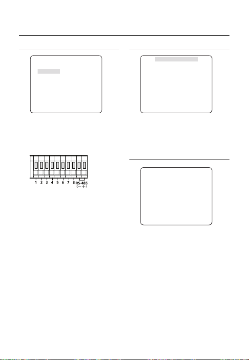
Jak korzystać z menu ekranowego
KOMUNIKACJA
eKOMUNIKACJAf
RS-485
PROTOKOL
PREDKOSC 9600
ADRES 0
Menu KOMUNIKACJA służy do konfi gurowania
ustawień dotyczących komunikacji przez interfejs
RS-485.
Kamerę podłącza się do interfejsu RS-485 przez
panel tylny.
[Złącze wejścia/wyjścia kamery]
Za pomocą przycisku
prędkość i adres (0~255) do komunikacji.
PROTOKOL
❖
Wybierz protokół komunikacji.
PREDKOSC
❖
Wybierz prędkość.
Uwaga :
Prędkość różni się w zależności od określonego
–
protokołu.
❖
ADRES
Należy określić niepowtarzalny adres dla każdej
kamery w tej samej sieci RS-485.
Aby sterować daną kamerą, należy dopasować
adres kamery z adresem nagrywarki DVR lub
sterownika.
cdef
[0~255]
SAMSUNG
określ protokół,
INFORMACJE O SYSTEMIE
eINFO O SYSTEMIEf
RODZAJ 3_BOX_NOR_N
PROTOKOL
ADRES 1
RODZAJ KOMUN. RS-485,HALF
PREDKOSC
NUM.SERYJNY 000000000000000
WERSJA KAMERY 0.50_090101
WERSJA EEPROM 0.50_090101
Można wyświetlić informacje o systemie, w tym
protokol, adres, predkosc, numer seryjny, wersja
kamery i wersja EEP.
SAMSUNG
9600
JEZYK
eJEZYKf
ENGLISH
PУCCKNЙ
ÃPOLSKI
ČESKY
TÜRKÇE
Kamera obsługuje 5 języków.
Wybierz preferowany język.
26 – CYFROWA KAMERA KOLOROWA

Jak korzystać z menu ekranowego
Tabela konfi guracji początkowej
❖
Konfi guracja kamery
•
ID KAMERY WYL.
PRZYSLONA ALC
AGC BARDZO WYS.
DET. RUCH (B.SZYBKO)
DNR MID
MIGAWKA WYL.
CZULOSC
AUTO x4
KOMP. MIGOTANIA (WYL.)
XDR MID
DZIEN/NOC AUTO
ZOOM CYFROWY WYL.
DETAL [2]
AGC KOLOR SUP MID
ODWROC WYL.
POSI/NEGA +
PIP WYL.
DIS WYL.
SYN.-PION INT
POL
Polski – 27

Dane techniczne
DANE TECHNICZNE
Elementy Elementy podrzędne SCC-B2333N
Typ kamery
Obraz
Skanowanie
Minimalne
oświetlenie sceny
Funkcje
Urządzenie 1/3-calowy przetwornik CCD Super-HAD IT
Piksele
System Przeplot
Linie
skanowania
Klatki 30 klatek/1 s
Częstotliwość
pozioma
Częstotliwość
pionowa
CZULOSC Nr F POZIOM DZIEN NOC
512 razy 1,2 50 IRE 0,0008 Lux 0,00008 Lux
512 razy 1,2 30 IRE 0,00047 Lux 0,000047 Lux
512 razy 1,2 15 IRE 0,00023 Lux 0,000023 Lux
Numer strefy prywatności 12 (metoda wielokątna)
DZIEN/NOC DZIEN/NOC/AUTO/ZEWNETRZNY
Detekcja ruchu WYL./ŚLEDZ./DETEKCJA
Funkcja rozszerzonego zakresu
dynamicznego(XDR)
Cyfrowy zoom x1 ~ x16 (x0,1 KROKU)
PIP WYL./WL.
Duża prędkość migawki
KOMP. MIGOTANIA WYL./WL.
CZULOSC x2 ~ x512
BLC WYL./WL. (ustawienie obszaru)
AGC WYL./WL. (ustawienie maksymalnego poziomu)
KONT. ELC WYL./WL. ( ~ 1/200K s)
Syn linii WYL./WL. (sterowanie fazą)
ID KAMERY WYL./WL. (Maks.54ea/2Linia)
Balans bieli ATW1/ATW2/AWC/3200K/5600K
Funkcja redukcji szumów cyfrowychDNR)
Cyfrowa stabilizacja obrazu(DIS)
Inteligentne wideo Fixed/Moved, Fence
Itd. Funkcja Detal, Odwroc (H/V), Posi/Nega
Kamera CCTV (DZIEN/NOC)
Razem 811 x 508
Efektywna 768 x 494
Tryb wewnętrzny
Tryb blokady linii
Tryb wewnętrzny
Tryb blokady linii
Stan Minimalne oświetlenie sceny
WYL. 1,2 50 IRE 0,4 Lux 0,04 Lux
WYL. 1,2 30 IRE 0,24 Lux 0,024 Lux
WYL. 1,2 15 IRE 0,12 Lux 0,012 Lux
WYL./WL. (Ustawienie poziomu)
1/60 ~ 1/10Ksec (OSD/Menu ekranowe/Sterowanie zewnętrzne)
WYL./WL. (Inteligentne 3D+2D)
525 linii
15.734 Hz
15.750 Hz
59,94 Hz
60 Hz
WYL./WL.
28 – CYFROWA KAMERA KOLOROWA

Dane techniczne
Elementy Elementy podrzędne SCC-B2333N
Rozdzielczosc
Wyjście wideo
Współczynnik
sygnał/szum
OBIEKTYW
Alarm
Pilot
Warunki otoczenia
Zasilanie
Dane techniczne
Pozioma 600 linii TV
Pionowa 350 linii TV
- VBS 1,0 Vp-p, 75 omów
Współczynnik sygnał/szum Ok. 52 dB
Typ napędu obiektywu RECZNY/AI (VIDEO/OB. DC)
Typ mocowania CS/C
Wejście N/D
Wyjście 1 wyjście
Coaxitron (dane przez przewód
koncentryczny)
RS-485 Yes (Multi Protocol, 8ea)
Temperatura robocza -10˚C ~ +50˚C
Wilgotność Mniej niż 90%
Wymagania dot. zasilania
Pobór mocy (z obiektywem DC)
Wskaźnik LED Tak
Wymiary (szer.
x wys. x głęb.)
Ciężar
Kolor Korpus Srebrny
Netto 64 (szer.) x 58 (wys.) x 109,2 (głęb.) mm
Opakowanie 173 (szer.) x 99 (wys.) x 115 (głęb.) mm
Netto 305g
Opakowanie 530g
Tak (z SCX-RD100))
AC24V ± 10%(60Hz ± 0,3Hz)
DC12V ± 10%
Podczas zwykłej pracy : 2,3W
Podczas przełączania fi ltra DZIEN/NOC: 2,8W
POL
Polski – 29
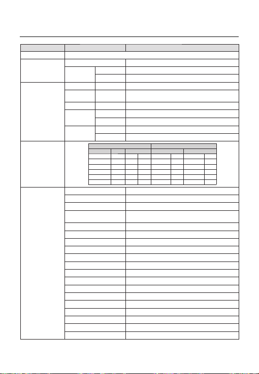
Dane techniczne
Elementy Elementy podrzędne SCC-B2333P / SCC-B2033P
Typ kamery
Obraz
Skanowanie
Minimalne
oświetlenie sceny
Funkcje
Urządzenie 1/3-calowy przetwornik CCD Super-HAD IT
Piksele
System Przeplot
Linie
skanowania
Klatki 25 klatek/1 s
Częstotliwość
pozioma
Częstotliwość
pionowa
CZULOSC Nr F POZIOM DZIEN NOC
512 razy 1,2 50 IRE 0,0008 Lux 0,00008 Lux
512 razy 1,2 30 IRE 0,00047 Lux 0,000047 Lux
512 razy 1,2 15 IRE 0,00023 Lux 0,000023 Lux
Numer strefy prywatności 12 (metoda wielokątna)
DZIEN/NOC DZIEN/NOC/AUTO/ZEWNETRZNY
Detekcja ruchu WYL./ŚLEDZ./DETEKCJA
Funkcja rozszerzonego zakresu
dynamicznego(XDR)
Cyfrowy zoom Maks. x16
PIP WYL./WL.
Duża prędkość migawki
KOMP. MIGOTANIA WYL./WL.
CZULOSC x2 ~ x512
BLC WYL./WL. (ustawienie obszaru)
AGC WYL./WL. (ustawienie maksymalnego poziomu)
KONT. ELC WYL./WL. ( ~ 1/200K s)
Syn linii WYL./WL. (sterowanie fazą)
ID KAMERY WYL./WL. (Maks.54ea/2Linia)
Balans bieli ATW1/ATW2/AWC/3200K/5600K
Funkcja redukcji szumów cyfrowychDNR)
Cyfrowa stabilizacja obrazu(DIS)
Inteligentne wideo Fixed/Moved, Fence
Itd. Funkcja Detal, Odwroc (H/V), Posi/Nega
Kamera CCTV (DZIEN/NOC)
Razem 795 x 596
Efektywna 752 x 582
625 linii
Tryb wewnętrzny
Tryb blokady linii
Tryb wewnętrzny
Tryb blokady linii
Stan Minimalne oświetlenie sceny
WYL. 1,2 50 IRE 0,4 Lux 0,04 Lux
WYL. 1,2 30 IRE 0,24 Lux 0,024 Lux
WYL. 1,2 15 IRE 0,12 Lux 0,012 Lux
1/50 ~ 1/10Ksec (OSD/Menu ekranowe/Sterowanie zewnętrzne)
15.625 Hz
15.625 Hz
50 Hz
50 Hz
WYL./WL. (Ustawienie poziomu)
WYL./WL. (Inteligentne 3D+2D)
WYL./WL.
30 – CYFROWA KAMERA KOLOROWA
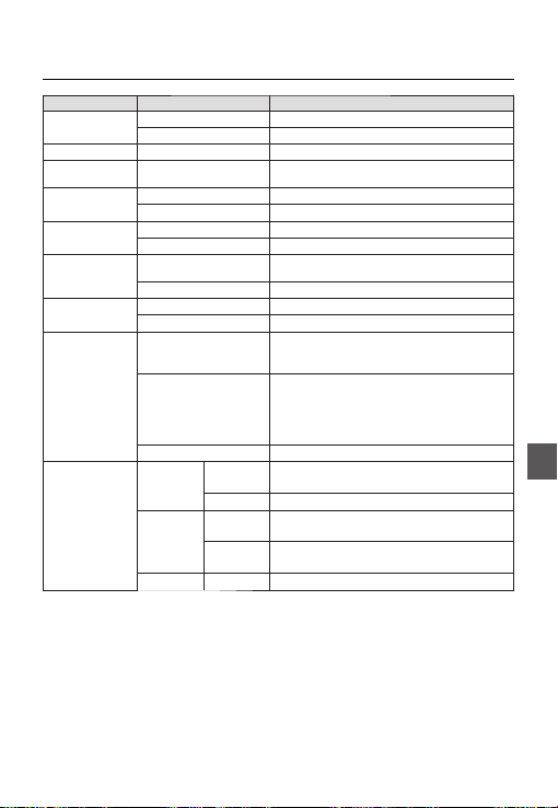
Dane techniczne
Elementy Elementy podrzędne SCC-B2333P / SCC-B2033P
Rozdzielczosc
Wyjście wideo
Współczynnik
sygnał/szum
OBIEKTYW
Alarm
Pilot
Warunki otoczenia
Zasilanie
Dane techniczne
Pozioma 600 linii TV
Pionowa 350 linii TV
- VBS 1,0 Vp-p, 75 omów
Współczynnik sygnał/szum Ok. 52 dB
Typ napędu obiektywu RECZNY/AI (VIDEO/OB. DC)
Typ mocowania CS/C
Wejście N/D
Wyjście 1 wyjście
Coaxitron (dane przez przewód
koncentryczny)
RS-485 Yes (Multi Protocol, 8ea)
Temperatura robocza -10˚C ~ +50˚C
Wilgotność Mniej niż 90%
Wymagania dot. zasilania
Pobór mocy (z obiektywem DC)
Wskaźnik LED Tak
Wymiary (szer.
x wys. x głęb.)
Opakowanie 173 (szer.) x 99 (wys.) x 115 (głęb.) mm
Ciężar
Opakowanie
Kolor Korpus Srebrny
SCC-B2333P : 64 (szer.) x 58 (wys.) x 109,2 (głęb.) mm
Netto
SCC-B2033P : 64 (szer.) x 58 (wys.) x 129,2 (głęb.) mm
Netto
Tak (z SCX-RD100))
SCC-B2333P : AC24V ± 10%(50Hz±0,3Hz)
DC12V ± 10%
SCC-B2033P : AC220V ± 10%(50Hz±0,3Hz)
Podczas zwykłej pracy :
SCC-B2333P : 2,3W
SCC-B2033P : 2,9W
Podczas przełączania fi ltra DZIEN/NOC :
SCC-B2333P :2,8W
SCC-B2033P : 3,4W
SCC-B2333P : ok. 305g
SCC-B2033P : ok. 395g
SCC-B2333P : ok. 530g
SCC-B2033P : ok. 620g
POL
Polski – 31

Prawidłowe usuwanie produktu (zużyty sprzęt elektryczny i elektroniczny)
To oznaczenie umieszczone na produkcie, akcesoriach lub dokumentacji oznacza, że po zakończeniu
eksploatacji nie należy tego produktu ani jego akcesoriów (np. ładowarki, zestawu słuchawkowego, przewodu
USB) wyrzucać wraz ze zwykłymi odpadami gospodarstwa domowego. Aby uniknąć szkodliwego wpływu na
środowisko naturalne i zdrowie ludzi wskutek niekontrolowanego usuwania odpadów, prosimy o oddzielenie
tych przedmiotów od odpadów innego typu oraz o odpowiedzialny recykling i praktykowanie ponownego
wykorzystania materiałów.
W celu uzyskania informacji na temat miejsca i sposobu bezpiecznego dla środowiska recyklingu tych
przedmiotów, użytkownicy w gospodarstwach domowych powinni skontaktować się z punktem sprzedaży
detalicznej, w którym dokonali zakupu produktu, lub z organem władz lokalnych.
Użytkownicy w firmach powinni skontaktować się ze swoim dostawcą i sprawdzić warunki umowy zakupu.
Produktu ani jego akcesoriów nie należy usuwać razem z innymi odpadami komercyjnymi.

SCC-B2333(P)
SCC-B2033P
DIGITÁLNÍ BAREVNÁ
KAMERA
uživatelská příručka
představte si své možnosti
Děkujeme, že jste se rozhodli pro výrobek společnosti Samsung.
Chcete-li zcela využívat všech služeb, zaregistrujte prosím
svůj výrobek na stránkách
www.samsungsecurity.com
CZE

bezpečnostní informace
UPOZORNĚNÍ
NEBEZPEČÍ ÚRAZU ELEKTŘINOU.
NEOTEVÍREJTE.
UPOZORNĚNÍ: PRO SNÍŽENÍ RIZIKA ÚRAZU ELEKTŘINOU NEODSTRAŇUJTE KRYT (NEBO ZADNÍ ČÁST) UVNITŘ NEJSOU
UPOZORNĚNÍ
Abyste zabránili požáru nebo úrazu elektřinou, nevystavujte zařízení dešti a vlhku.
•
UPOZORNĚNÍ
Používejte pouze standardní adaptér uvedený v technickém popisu. Při použití jiného adaptéru by mohlo
1.
dojít k požáru, úrazu elektřinou nebo poškození produktu.
Nesprávné připojení napájení nebo výměna baterie může způsobit explozi, požár, úraz elektřinou nebo
2.
poškození produktu.
Nepřipojujte k jednomu adaptéru více kamer. Překročení kapacity může způsobit nadměrné zahřátí nebo
3.
požár.
Připojte napájecí kabel pevně k zásuvce. Volné připojení může způsobit požár.
4.
Při instalaci kameru zajistěte pevně a bezpečně. Při pádu kamery by mohlo dojít ke zranění.
5.
Neumisťujte na kameru vodivé předměty (např. šroubováky, mince, kovové předměty atd.) ani nádoby
6.
s vodou. Mohlo by dojít ke zranění kvůli požáru, úrazu elektřinou nebo zranění způsobenému pádem
předmětu.
Neinstalujte jednotku ve vlhkém nebo prašném prostředí nebo prostředí plném sazí. Mohlo by dojít k požáru
7.
nebo úrazu elektřinou.
Pokud z jednotky bude vycházet neobvyklý zápach nebo kouř, přestaňte produkt používat. V takovém
8.
případě okamžitě odpojte napájecí zdroj a obraťte se na servis. Budete-li za takové situace pokračovat v
používání může dojít k požáru nebo úrazu elektřinou.
Pokud nebude produkt fungovat normálně, obraťte se na nejbližší servis. Nikdy tento produkt sami
9.
nerozebírejte ani neupravujte. (Společnost SAMSUNG není zodpovědná za problémy způsobené
neoprávněnými úpravami nebo pokusy o opravu.)
10.
Při čištění nestříkejte vodu přímo na produkt. Mohlo by dojít k požáru nebo úrazu elektřinou.
ŽÁDNÉ UŽIVATELEM OPRAVITELNÉ ČÁSTI, PŘENECHTE OPRAVY NA ODBORNÍKOVI
Tento symbol označuje nebezpečné napětí uvnitř jednotky, které představuje nebezpečí
úrazu elektřinou.
Tento symbol označuje důležité pokyny k používání nebo údržbě v doprovodné
dokumentaci.
2 – DIGITÁLNÍ BAREVNÁ KAMERA

bezpečnostní informace
UPOZORNĚNÍ
Zabraňte pádu předmětů na produkt a nevystavujte jej silným nárazům. Nevystavujte produkt
1.
příliš silným vibracím ani magnetickému rušení.
Neinstalujte produkt v prostředí vystavenému vysokým teplotám (přes 50 °C), nízkým teplotám
2.
(pod -10 °C) nebo vysoké vlhkosti. Mohlo by dojít k požáru nebo úrazu elektřinou.
Chcete-li přemístit již nainstalovaný produkt, vypněte napájení a až poté jej přesuňte.
3.
Při bouřkách odpojte napájecí kabel od zásuvky. V opačném případě by mohlo dojít k požáru
4.
nebo poškození produktu.
Uchovávejte mimo dosah přímého slunečního záření a tepelných zdrojů. Mohlo by dojít k požáru.
5.
Produkt nainstalujte v prostředí s dobrou ventilací.
6.
Nemiřte kamerou přímo proti extrémně jasným předmětům, například slunci, jinak může dojít k
7.
poškození obrazového snímače CCD.
Nevystavujte přístroj kapající nebo stříkající tekutině a neumisťujte na přístroj předměty s
8.
tekutinami, například vázy.
9.
K odpojení zařízení slouží napájecí zástrčka, která by měla být neustále přístupná.
CZE
Česky – 3

Důležité bezpečnostní pokyny
1.
Přečtěte si tyto pokyny.
2.
Dodržujte tyto pokyny.
3.
Řiďte se všemi upozorněními.
4.
Postupujte podle všech pokynů.
5.
Nepoužívejte přístroj v blízkosti vody.
6.
Čistěte pouze suchým hadříkem.
7.
Neblokujte větrací otvory. Instalaci proveďte podle pokynů výrobce.
8.
Neinstalujte produkt v blízkosti tepelných zdrojů, jako jsou topení, akumulační kamna nebo jiné
přístroje (například zesilovače).
9.
Nepřekonávejte bezpečnostní účel polarizované zástrčky nebo zástrčky s uzemněním.
Polarizovaná zástrčka má dva konektory, z nichž jeden je širší než ten druhý. Zástrčka s
uzemněním má dva konektory a třetí konektor pro uzemnění. Široký konektor a třetí konektor mají
bezpečnostní význam. Pokud dodaná zástrčka neodpovídá vaší elektrické zásuvce, obraťte se na
elektrikáře, který zastaralou zásuvku vymění.
10.
Zabraňte tomu, aby se na napájecí kabel šlapalo nebo aby docházelo k jeho
skřípnutí, zejména u zástrček, zásuvek a v místě, kde vychází z přístroje.
11.
Používejte pouze doplňky a příslušenství doporučené výrobcem.
12.
Používejte pouze s vozíkem, stojanem, stativem, držákem nebo stolem
doporučeným výrobcem nebo prodávaným s přístrojem.
13.
Odpojte přístroj. V případě použití vozíku buďte při přesouvání vozíku s přístrojem opatrní, aby
nedošlo ke zranění převržením vozíku.
14.
Přenechejte veškerý servis kvalifi kovanému servisnímu personálu. Servis je vyžadován, pokud
byl přehrávač poškozen jakýmkoliv způsobem, jako například při poškození napájecí šňůry nebo
zástrčky, při rozlití tekutiny nebo pádu předmětů do přístroje, vystavení přehrávače dešti nebo
vlhkosti, pokud přehrávač nefunguje normálně nebo pokud spadnul.
4 – DIGITÁLNÍ BAREVNÁ KAMERA
 Loading...