

Page 1
WDR DAY/NIGHT COLOUR CAMERA
SCC-B2315(P)/SCC-B2015P
User Manual
ENG
TUR
Page 2
Safety Precautions
CAUTION
RISK OF ELECTRIC
SHOCK DO NOT OPEN
CAUTION: TO REDUCE THE RISK OF
ELECTRIC SHOCK, DO NOT REMOVE REAR
COVER. NO USER SERVICEABLE PARTS
INSIDE. REFER TO QUALIFIED SERVICE
PERSONNEL.
This symbol indicates high voltage is present inside. It is dangerous
to make any kind of contact with any inside part of this product.
This symbol alerts you that important literature concerning
operation and maintenance has been included with this product.
To prevent damage which may result in fire or electric shock hazard, do
not expose this appliance to rain or moisture.
WARNING
1. Be sure to use only the standard adapter that is specified in the
specification sheet. Using any other adapter could cause fire,
electrical shock, or damage to the product
2. Incorrectly connecting the power supply or replacing battery may
cause explosion, fire, electric shock, or damage to the product.
3. Do not connect multiple cameras to a single adapter. Exceeding the
capacity may cause abnormal heat generation or fire.
4. Securely plug the power cord into the power receptacle. Insecure
connection may cause fire.
5. When installing the camera, fasten it securely and firmly. A falling
camera may cause personal injury.
6. Do not place conductive objects (e.g. screwdrivers, coins, metal
things, etc.) or containers filled with water on top of the camera.
Doing so may cause personal injury due to fire, electric shock, or
falling objects.
7. Do not install the unit in humid, dusty, or sooty locations. Doing so
may cause fire or electric shock.
8. If any unusual smells or smoke come from the unit, stop using the
product. In such case, immediately disconnect the power source and
contact the service centre. Continued use in such a condition may
cause fire or electric shock.
9. If this product fails to operate normally, contact the nearest service
centre. Never disassemble or modify this product in any way.
(SAMSUNG is not liable for problems caused by unauthorized
modifications or attempted repair.)
1
0. When cleaning, do not spray water directly onto parts of the product.
Doing so may cause fire or electric shock.
2 3
2
Page 3

ENG
CAUTION
1. Do not drop objects on the product or apply strong shock to it. Keep
away from a location subject to excessive vibration or magnetic
interference.
2. If you want to relocate the already installed product, be sure to turn
off the power and then move or reinstall it.
3. Remove the power plug from the outlet when then there is a
lightning. Neglecting to do so may cause fire or damage to the
product.
4. Keep out of direct sunlight and heat radiation sources. It may cause
fire.
5. Install it in a place with good ventilation.
6. Avoid aiming the camera directly towards extremely bright objects
such as sun, as this may damage the CCD image sensor.
7. Apparatus shall not be exposed to dripping or splashing and no
objects filled with liquids, such as vases, shall be placed on the
apparatus.
8. The Mains plug is used as a disconnect device and shall stay readily
operable at any time.
FCC Statement
This device complies with part 15 of the FCC Rules. Operation is subject
to the following two conditions:
1) This device may not cause harmful interference, and
2) This device must accept any interference received including
interference that may cause undesired operation.
Note
This equipment has been tested and found to comply with the limits
for a Class A digital device, pursuant to part 15 of FCC Rules. These
limits are designed to provide reasonable protection against harmful
interference when the equipment is operated in a commercial
environment. This equipment generates, uses, and can radiate radio
frequency energy and, if not installed and used in accordance with
the instruction manual, may cause harmful interference to radio
communications. Operation of this equipment in a residential area
is likely to cause harmful interference in which case the user will be
required to correct the interference at his own expense.
Page 4

Important Safety Instructions
1. Read these instructions.
2. Keep these instructions.
3. Heed all warnings.
4. Follow all instructions.
5. Do not use this apparatus near water.
6. Clean only with dry cloth.
7. Do not block any ventilation openings. Install in
accordance with the manufacturer’s instructions.
8. Do not install near any heat sources such as radiators,
heat registers, or other apparatus (including amplifiers)
that produce heat.
9. Do not defeat the safety purpose of the polarized or
grounding-type plug. A polarized plug has two blades with
one wider than the other. A grounding type plug has two
blades and a third grounding prong. The wide blade or
the third prong is provided for your safety. If the provided
plug does not fit into your outlet, consult an electrician
for replacement of the obsolete outlet.
10. Protect the power cord from being walked on or pinched
particularly at plugs, convenience receptacles, and the
point where they exit from the apparatus.
11. Only use attachments/accessories specified by the
manufacturer.
12. Use only with cart, stand, tripod, bracket, or table
specified by the manufacturer, or sold with the apparatus.
13. Unplug this apparatus. When a cart is used, use caution
when moving the cart/apparatus combination to avoid
injury from tip-over.
14. Refer all servicing to qualified service personnel.
Servicing is required when the apparatus has been
damaged in any way, such as power-supply cord or plug
is damaged, liquid has been spilled or objects have fallen
into the apparatus, the apparatus has been exposed to
rain or moisture, does not operate normally, or been
dropped.
4 5
Page 5

ENG
Contents
Safety Precautions ...... 2
Important Safety
Instructions ..................... 4
Contents ........................... 5
Overview ........................... 6
Special Features ........... 7
Part Names and
Functions ......................... 8
Side View ......................... 8
Rear Panel ....................... 10
Installation ....................... 13
Before Installation ......... 13
Checking the contents
of the package ..................
Things to keep in mind during
installation and use .............13
Connecting the Auto Iris
Lens Connector ................
Installing the Camera ... 15
Mounting the lens .............
Setting the ALC lens
selection switch ................
Adjusting the back focus .... 16
Connecting cables and
checking operation ...........
Camera Setup ................ 19
CAMERA ID ........................
IRIS ...................................... 20
WDR... ............................. 20
ALC... ............................... 21
ELC... ............................... 22
SHUTTER .........................22
AGC ................................... 23
MOTION ............................ 24
MOTION DET ................... 24
DAY/NIGHT ...................... 26
DAY... ...............................
NIGHT... ...........................
AUTO... ............................
EXT .................................. 29
WHITE BAL ...................... 29
13
PRIVACY ........................... 30
SPECIAL ........................... 31
LANGUAGE ..................... 31
V-SYNC ............................
14
DIGITAL ZOOM ...............
VIDEO SET ......................
15
DNR ................................. 33
FLICKERLESS ................. 33
16
SYSTEM INFO ................
RS-485 ............................... 34
EXIT ................................... 35
17
Product
Specifications ................ 36
20
27
28
28
31
32
32
34
Page 6

Overview
This enriched WDR (Wide Dynamic Range) Day/Night camera can
clearly implement both dark and bright parts on the screen with the
dual shutter.
When a bright object such as window occupies a part of the screen, it
appears white in conventional cameras. But using the state-of-the-art
WDR function that this camera provides, you can see the clear image.
This Day/Night camera activates the colour mode when in the
illumination over the normal value. Otherwise it activates B/W (Black/
White) mode by removing the IR cut function, which can improve the
sensitivity for identifying objects even in a dark area.
It also incorporated the low speed shutter and Sens Up (Uses the
field accumulation method) functions to enhance the low illumination
feature.
This camera can be mainly used in the dark places such as
basement parking lots under comparatively low illumination. In
daytime, it displays the colour screen with a horizontal resolution of
540 lines but at night, it uses the Day/Night feature along with the
Sens Up function to identify objects in a dark area. You can also
connect the infrared ray emission equipment to this camera.
DAY/NIGHT
This function can make the IR Cut filtering function inactive under
the illumination below the normal value.
6 7
Page 7

ENG
Special Features
High Sensitivity
It implements images of high sensitivity using the up-to-date SuperHAD P/S CCD.
WDR
The WDR function of this camera is the state-of-the-art technology
that can effectively enlarge the range for screen gain. It is mainly
used for taking photos for window scenes inside a building. Using
this technology, you can clearly see both indoor and outdoor
images, and can enjoy the excellent picture quality, which is
enabled by automatically adjusting the WDR level.
Low Illumination
It uses the digital signal technologies such as low illumination and
Day/Night functions that make your camera identify objects even in
the worst environment.
Superior Backlight Adjustment
When an object has a bright illumination or sunlight behind it, this
camera automatically improves the shaded object picture quality.
Digital Power Synchronization
The full digital Line Lock function directly adjusts the vertical
camera synchronization to enhance the operationability and
reliability of this camera.
High Resolution
This camera has realized high resolution of 540 lines using the
top-notch full digital image processing and special algorithm
technologies.
Output Signal Setting
You can set the following Video output signals: Image reversion
(Horizontal, Vertical, or both), Privacy, Horizontal/Vertical profiling,
and digital zooming.
Page 8
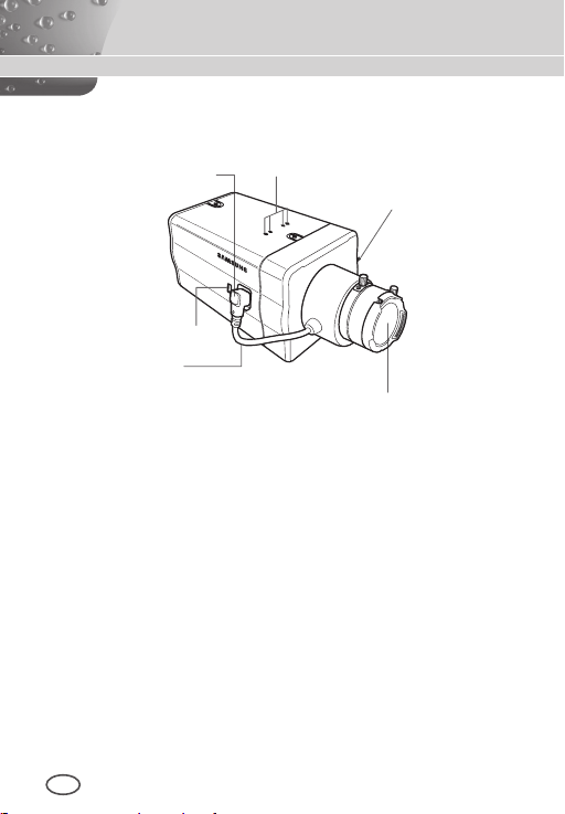
Part Names and Functions
Side View
❚
1 Auto Iris Lens
Connector
5
ALC Lens
Selection Switch
4
Automatic Shutter
Lens Control Cable
1 Auto Iris Lens Connector
This groove is used for screwing the mount adapter, a part of the
bracket where the camera will be installed.
2 Mount Adapter Fixing Grooves
These grooves are used when fixing screws of the mount
adapter connected to the bracket when installing the camera on it.
3 Back Focus Control Bar
You can adjust the back focus by moving it up and down.
4 Automatic Shutter Lens Control Cable
This cable transmits the power and signals from the camera for
controlling the lens shutter.
2 Mount Adapter
Fixing Grooves
3 Back Focus
Control Bar
Camera Lens
8 9
Page 9

ENG
5 ALC Lens Selection Switch
This switch is used to select the type of the Auto Iris lens for
use. After this setting, you have to also set the lens type in the
Setup menu (In ALC… and WDR… submenus of IRIS).
DC: When the Auto Iris lens is installed for DC control
signals, set the switch to “DC.”
VIDEO: When the Auto Iris lens is installed for Video
control signals, set the switch to “VIDEO.”
Auto Iris Lens (Optional)
This lens is installed on this camera.
Note
When the camera lens becomes dirty, softly clean it with a lens
tissue or a cloth soaked in pure ethanol.
Page 10
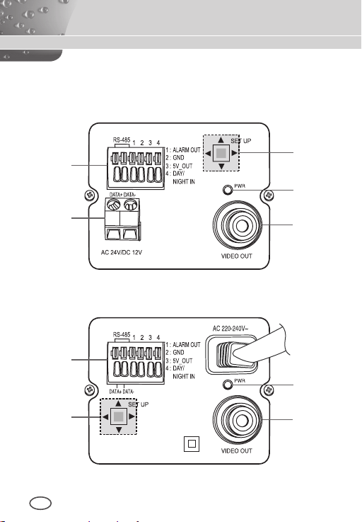
Rear Panel
❚
AC24/DC12V(SCC-B2315, B2315P)
1
5
2
3
4
AC220V~240V(SCC-B2015P)
1
3
2
10 11
4
Page 11
ENG
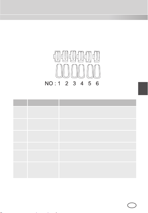
1 Input/Output Connector
This connector has input and output jacks for RS-485 control
signals, Day & Night switching, and alarm output signals.
No
.
Function Description
1 RS-485 DATA+ Jack for connection to RS-485 DATA+
2 RS-485 DATA- Jack for connection to RS-485 DATA-
3 ALARM OUT Alarm out jack for motion detection
4 GROUND Grounding jack.
5 DC +5V Power supply jack for RS-485 JIG. Use
6 EXTERNAL
SENSOR
.
signal line
signal line.
(Open Collector, On Gnd)
within typical DC +5V 100mA
Input jack for Day & Night conversion.
High (DC +3V~+5V): Day mode
Low (0V): Night mode
.
Page 12

2 Setup Switch
This switch is used to set the function or property. When this
switch is pressed for at least 2 seconds, the Setup menu
appears.
[Left/Right] movement or changing the displayed value:
By pressing this switch left or right, you can move left or
right on the menu or change the displayed value.
[Up/Down] movement: By pressing this switch up or
down, you can move up or down on the menu.
Setting: When you press this switch in the menu, the
selected value or function is confirmed. To enter a
submenu, press this button.
3 Power Display LED
When the power is normally connected, the red LED lights.
4 Video OUT Jack
This is connected to the Video Input jack of the monitor and it
outputs the Video signals.
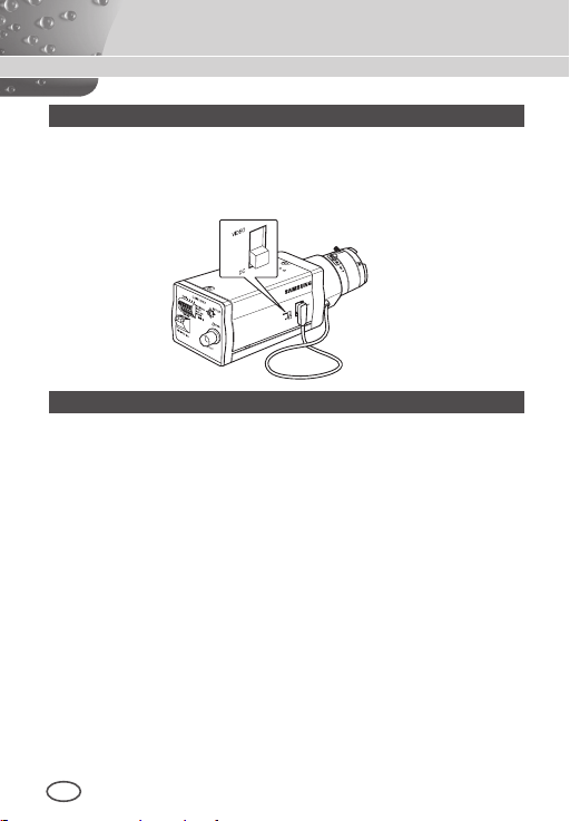
5 Power Connection Jack
This is connected to the Power cable.
12 13
Page 13
ENG
Installation
Before Installation
❚
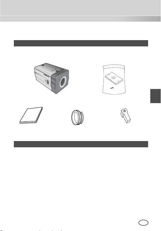
Checking the contents of the package
Make sure that the following items are included in the package.
Camera Camera Holder(Mount)
User's Manual
C Mount Adapter
Auto Iris
Lens Connector
Things to keep in mind during installation and use
Do not disassemble the camera on your own.
Always be careful when handling the camera. Do not
strike the camera by your fists or shake it. Please be
careful not to be careless when storing and operating it.
Do not place or operate the camera in any wet
environment such as rain or wet surfaces.
Do not clean the camera with rough sandpaper. Please
always use a dry cloth when cleaning it.
Put the camera in a cool area free from direct sunlight.
Otherwise, the camera may be damaged.
Page 14
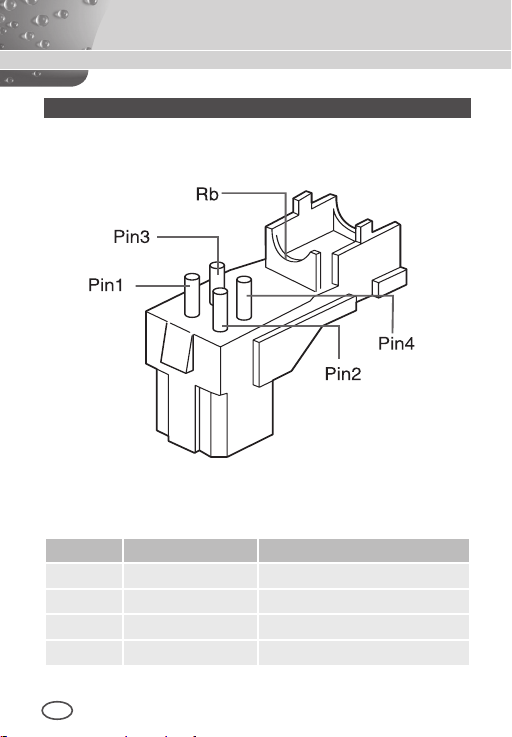
Connecting the Auto Iris Lens Connector
The Auto Iris Lens Connector that is provided with your camera
consists of the following parts:
Connect each uncovered shutter control cables to the Auto Iris Lens
Connector as the following:
Pin No. DC Control Type Video Control Type
1 Damp(-) Power (+12V)
2 Damp(+) Not applicable
3 Drive(+) Video Signal
4 Drive(-) Ground
14 15
Page 15
ENG
Installing the Camera
❚
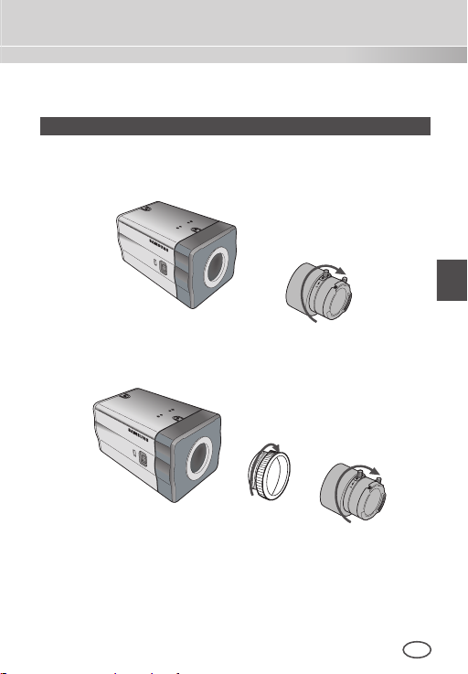
Mounting the lens
When using the CS lens
Mount the CS lens by rotating it clockwise as shown in the picture:
CS lens
When using the C lens
After mounting the C-mount adapter by rotating it clockwise, turn the
C lens clockwise until it is fixed as shown in the picture.
C lens
Page 16
Setting the ALC lens selection switch
N
You can set the lens selection switch located on the side of the camera
according to the lens type. When the mounted lens is an auto Iris lens
of DC control type, set the switch to “DC.” When the mounted lens is
an auto Iris lens of Video control type, set the switch to “VIDEO.”
Adjusting the back focus
The back focus of the camera is adjusted at the factory before delivery but
some lenses can be out of focus depending on the lens type. In this case,
you have to adjust the back focus. The following describes how to adjust
the back focus of the lenses.
In case of the lens with no zooming function
① After exposing the camera to an object with high resolution (like
a dart-patterned image) at a distance of more than 10m, set the
lens focus ring to infinite (∞).
➁ Adjust the Back Focus Control Bar until the object is of best quality.
➂ Fix the screw of the Back Focus Control Bar.
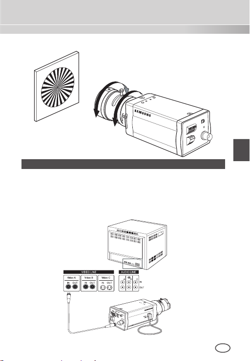
In case of the lens with zooming function
① After exposing the camera to an object with high resolution (like
a dart-patterned image) at a distance of 3 to 5m, fully rotate the
lens zoom to the TELE direction. Then adjust the lens focus ring
until the object is of best quality.
➁ Fully rotate the lens zoom to the WIDE direction and adjust the
Back Focus Control Bar until the object is of best quality.
➂ Repeat step 1 and 2 two or three times until the focuses of Zoom
TELE and Zoom WIDE are clear enough.
16 17
Page 17
ENG
Connecting cables and checking operation
N
1. Connect one end of the BNC cable to the VIDEO OUT jack on
the rear of the camera.
2. Connect another end of the BNC cable to the VIDEO IN jack on
the monitor.
Video In Terminal of
Monitor Rear Surface
BNC cable
Video Out Terminal
Page 18
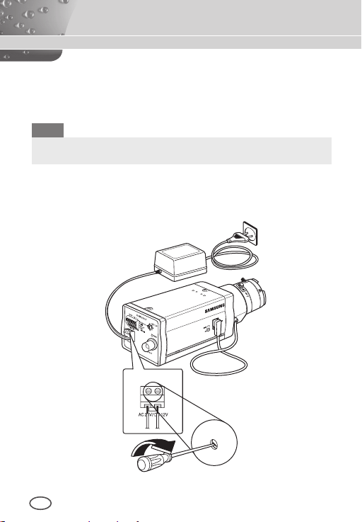
3. Finally connect the power adapter to the camera. You can
N
connect 2 lines of the power adapter to the camera using the
Slot Head screwdriver as shown in the picture.
(GND: cable with the white stripe line
)
Note
Connect any power source of AC 24V and DC 12V irrespective
of polarity.
18 19
Page 19
ENG
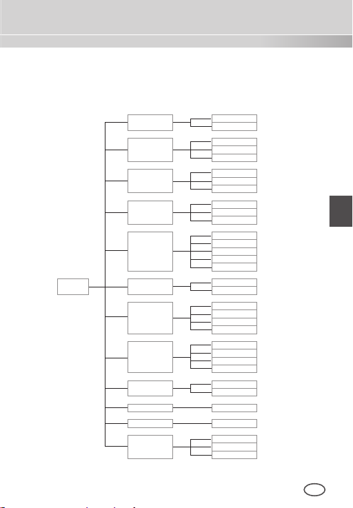
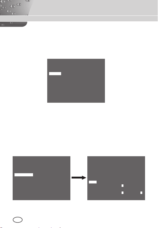
Camera Setup
This chapter describes how to configure the camera-related settings. If you
press the Setup switch for at least 2 seconds, the Setup menu appears.
The Setup OSD (On-screen Display) map brief is like the following:
ON...
OFF
WDR...
ALC...
ELC...
OFF
AUTO X2 to X256
1/100 (or 1/120) to 1/10K
OFF
LOW
HIGH
NORM
FAST
F.Fast
S.SLOW
SLOW
ON...
OFF
DAY...
NIGHT...
AUTO...
EXT
ATW1
ATW2
AWC
MANU...
OFF
ON...
QUIT
SAVE
PRESET
SETUP
MENU
CAMERA ID
IRIS
SHUTTER
AGC
MOTION
MOTION DET
DAY/NIGHT
WHITE BAL
PRIVACY
SPECIAL ...
RS485 ...
EXIT
Page 20
❚
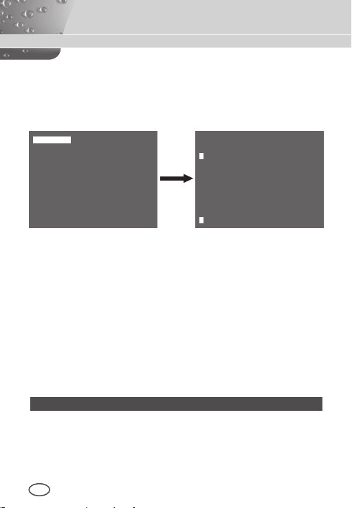
CAMERA ID
This CAMERA ID menu is used to assign a camera ID to this
camera. If you press the Setup switch when the CAMERA ID menu
is selected, the corresponding setup screen appears.
CAMERA ID ON...
IRIS ALC...
SHUTTER OFF
AGC HIGH
MOTION DET OFF
DAY/NIGHT DAY...
WHITE BAL ATW2
PRIVACY OFF
SPECIAL ...
RS-485 ...
EXIT QUIT
(CAMERA ID)
ABCDEFGHIJKLMNOPQRSTUVWXYZ
0123456789 : ! - + * ()
RET
SP▶▶ ◀◀SP LOCATION...
CAMERA-1...........
/
You can input a camera ID composed of alphabets, numbers, and
special characters up to 20 characters long. The input camera
ID can be displayed at the desired location when using the
LOCATION… submenu.
When you press the Setup switch in RET, the screen returns to the
upper menu.
❚
IRIS
The IRIS menu is used to set the automatic light control method
for this camera. After setting the ALC Lens Selection Switch
,
select any of DC LENS and VIDEO LENS in the ALC... and WDR...
submenus.
WDR...
If you press the Setup switch when the WDR… submenu is selected, the corresponding screen appears.
20 21
Page 21
ENG
CAMERA ID OFF
IRIS WDR...
SHUTTER OFF
AGC HIGH
MOTION DET OFF
DAY/NIGHT DAY...
WHITE BAL ATW2
PRIVACY OFF
SPECIAL ...
RS-485 ...
EXIT QUIT
(WDR)
TYPE DC LENS
LEVEL1 L � � � I � � � H
LEVEL2 L � � � I � � � H
WHITE BAL INDOOR
RET
First select any of DC LENS, VIDEO LENS, and MANU in TYPE.
You can adjust the shutter speed in LEVEL 1 and the brightness in
LEVEL 2. You can also select any of ALL, OUTDOOR, and INDOOR
in WHITE BAL. In case of ALL, this camera controls both indoor and
outdoor images.
ALC...
If you press the Setup switch when the ALC… submenu is selected,
the corresponding screen appears. First select any of DC LENS and
VIDEO LENS in TYPE.
CAMERA ID OFF
IRIS ALC...
SHUTTER OFF
AGC HIGH
MOTION DET OFF
DAY/NIGHT DAY...
WHITE BAL ATW2
PRIVACY OFF
SPECIAL ...
RS-485 ...
EXIT QUIT
You can
make the BLC (Back Light Compensation) function active
or not. For setting the BLC zone, you can select any of BOTTOM…,
TOP…, LEFT…, RIGHT…, and CENTRE… The actual location is
displayed when you enter each item.
In case of USER…, you can set the desired BLC zone by defining
the size and location. You can set the Video output level in LEVEL.
(ALC)
TYPE DC LENS
BLC OFF
LEVEL ( 0) � � � � I � � � �
RET
Its selectable range is from -9 to +9.
Page 22
ELC...
If you press the Setup switch when the ELC… submenu is selected,
the corresponding screen appears. You can make the ELC (Elec
-
tronic Light Control) function active or not.
CAMERA ID OFF...
IRIS ELC...
SHUTTER OFF
AGC HIGH
MOTION DET ON...
DAY/NIGHT DAY...
WHITE BAL ATW2
PRIVACY OFF
SPECIAL ...
RS-485 ...
EXIT QUIT
(ELC)
BLC OFF
LEVEL ( 0) � � � � I � � � �
RET
Like the same as the ALC configuration, you can set the BLC zone
and assign the level of the high speed shutter.
SHUTTER
❚
The SHUTTER menu is used to set the high speed electronic
shutter and AUTO low speed shutter.
The high speed electronic shutter can be used 7 different speeds
and is commonly used for imaging fast moving objects.
(NTSC: from 1/100 to 1/10K, PAL: from 1/120 to 1/10K ). The low
speed electronic shutter can be any of 13 speeds from X2 to X256
and it slows the shutter speed to make images clearer in dark
illumination. If you select an AUTO low speed, the shutter speed is
automatically lowered depending on the darkness level.
CAMERA ID OFF
IRIS ALC...
SHUTTER AUTO X4
MOTION SLOW
MOTION DET OFF
DAY/NIGHT DAY...
WHITE BAL ATW2
PRIVACY OFF
SPECIAL ...
RS-485 ...
EXIT QUIT
22 23
Page 23
ENG
If you keep pressing the LEFT/RIGHT Setup switch, shutter speeds
toggles in the following order:
OFF AUTO X2 AUTO X4 AUTO X6 AUTO X8
AUTO X12 AUTO X16 AUTO X24 AUTO X32 AUTO X48
AUTO X64 AUTO X96 AUTO X128 AUTO X256 OFF
1/100 (NTSC), 1/120 (PAL) 1/250 1/500 1/1000 1/2000
1/4000 1/10K
Note
When the IRIS mode is ELC or WDR, you cannot use high speed
shutters.
AGC
❚
The AGC (Auto Gain Control) menu is used to set the AGC level
of the camera. When the AGC is active, the camera automatically
increases the sensitivity by amplifying the Video signal when the
strength of the signal falls below the normal value.
CAMERA ID OFF
IRIS ALC...
SHUTTER OFF
AGC LOW
MOTION DET OFF
DAY/NIGHT DAY...
WHITE BAL ATW2
PRIVACY OFF
SPECIAL ...
RS-485 ...
EXIT QUIT
Only when OFF or a high speed shutter is selected in the
SHUTTER menu, you can set the AGC level.
You can select any of OFF, LOW, and HIGH.
Note
When the DAY/NIGHT is set to AUTO, the AGC is displayed with
--- so you cannot change its setting.
Page 24
MOTION
❚
The MOTION menu is used to set the intensity of the camera AGC
level for monitoring motions. This function is available only in AUTO
low speed mode. You can select any of S.SLOW, SLOW, NORM,
FAST, and F.FAST according to the AGC intensity level.
CAMERA ID OFF
IRIS ALC...
SHUTTER AUTO X2
MOTION SLOW
MOTION DET OFF
DAY/NIGHT DAY...
WHITE BAL ATW2
PRIVACY OFF
SPECIAL ...
RS-485 ...
EXIT QUIT
To monitor very fast moving objects in dark illumination, select
F.FAST. To monitor non-moving objects in dark illumination, select
S.SLOW.
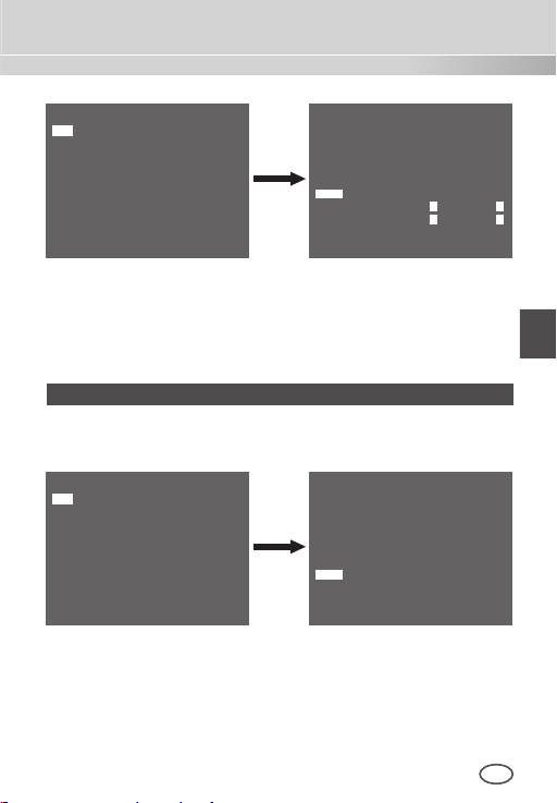
MOTION DET
❚
The MOTION DET menu is used to configure the motion detection
related settings. If you press the Setup switch when ON… is selected
in the MOTION DET menu, the corresponding screen appears.
CAMERA ID OFF
IRIS ALC...
SHUTTER OFF
AGC HIGH
MOTION DET ON...
DAY/NIGHT DAY...
WHITE BAL ATW2
PRIVACY OFF
SPECIAL ...
RS-485 ...
EXIT QUIT
(MOTION DET)
TYPE 1
AREA
DISPLAY ON
SENSITIVITY
RET
0 1 2 3
L � � � � I � � H
24 25
Page 25

ENG
There are 3 different types like 1, 2, and 3. You cannot change the
setting for type 2 because it is prefixed with the full screen. In case of 1
and 3, you can set the motion detection area on your own.
Those 3 types are like the following:
1. Window type: The selected area is displayed with a box. The
motion can be detected for the area only.
You can manually set the motion detection area. You can use the
UP/DOWN/LEFT/RIGHT Setup switch to set the size. To move to
POSITION, press the switch. After setting the position using the
UP/DOWN/LEFT/RIGHT Setup switch, press the Setup switch to
move to the upper menu. To set the size and position for AREA,
select any of 0, 1, 2, and 3.
Window0
Window1
2. Label type: The box-typed motion detection area is prefixed. The
detected area is displayed with size and position changing. You
cannot change AREA because it is displayed with “---.”
Label2
Label1
Label3
Label0
Page 26

3. Block type: The screen displays with small blocks. When a motion
is detected in the selected blocks, the small blocks are displayed
on the screen.
PRESET: The whole screen becomes the motion
detection area.
USER...: You can manually set the motion detection area.
Use the UP/DOWN/LEFT/RIGHT Setup switch to set the
area. To erase the selected block, press the Setup switch.
In order to set the motion detection area on your own, you have to
specify the size and location for the area setting.
When ON is selected in DISPLAY, the detected motion is displayed
on the screen and the camera sends the Alarm Out signal.
You can also assign the sensitivity for motion detection.
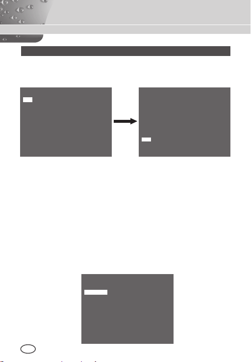
DAY/NIGHT
❚
The DAY/NIGHT menu is used to configure the day and night
related settings for this camera. This camera can turn the IR
(Infrared) filter on or off.
CAMERA ID OFF
IRIS ALC...
SHUTTER OFF
AGC HIGH
MOTION DET OFF
DAY/NIGHT DAY...
WHITE BAL ATW2
PRIVACY OFF
SPECIAL ...
RS-485 ...
26 27
EXIT QUIT
Page 27

ENG
Note
In case of B/W mode, it may fail to focus when B/W mode is
converted to Color mode.
That is because it must have the condition to have IRIS opened for
the maximum before adjusting the Back-Focus.
The smaller the F number of lens is, the lower the focus depth of
field is (e.g. Using a high speed electronic shutter may lower the
depth of the camera).
It is required to set the focus under the condition that IRIS is open
for the maximum in color mode.
DAY...
If you press the Setup switch when the DAY… submenu is selected,
the corresponding screen appears. You can set the values for
C-GAIN, AGC COLOUR, AGC DETAIL, and C-KNEE in Day mode.
Colour images are implemented by these settings.
(DAY)
C-GAIN (7) � � � � � � I
AGC COLOR ( 0) � � � � I � � � �
AGC DETAIL (7)
C-KNEE (5) � � � � � I � �
RET
I � � � � � � �
Note
When the value of AGC DETAIL becomes large, it also makes the
noise stand out.
Page 28

NIGHT...
If you press the Setup switch when the NIGHT… submenu is selected, the corresponding screen appears.
(NIGHT)
COLOR/BW COLOR...
RET
Even in night mode, you can see colour images in bright illumination. Therefore you can select any of COLOUR… and BW… In case
of COLOUR…, you have to set the colour temperature for white
balance. You can also specify the settings for red and blue colours
on your own.
In case of BW..., when the BURST is set to ON, the burst
signals are output with the BW Composite Video signals. And no burst
signals are output when the BURST is set to OFF.
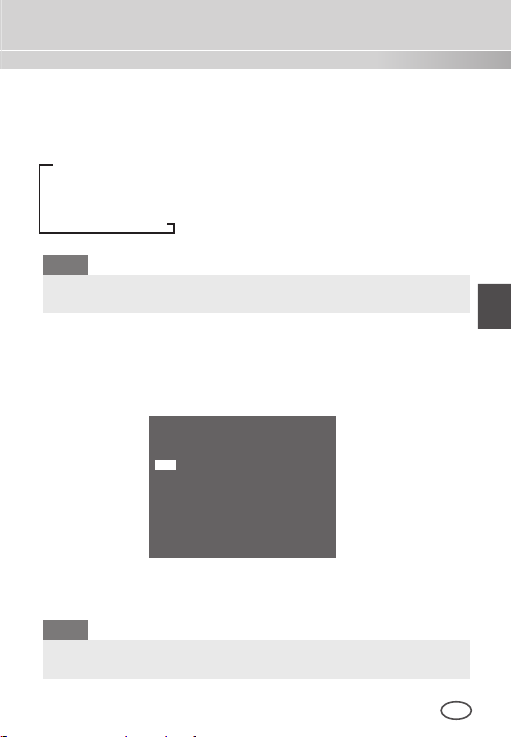
AUTO...
This automatically converts the DAY mode to NIGHT mode and vice
versa depending on illumination. In low illumination, it removes the IR
filtering function to raise the sensitivity. Otherwise, it activates the IR
filtering function to lower the sensitivity.
If you press the Setup switch when the AUTO… submenu is
selected, the corresponding screen appears.
(AUTO)
LEVEL ( 0) I � � � � � � � �
DAY
NIGHT 2 S
NIGHT DAY 5 S
28 29
RET
Page 29

ENG
For this function, you can specify the level for each conversion
between Day and Night.
Note
When the DAY/NIGHT is set to AUTO, the AGC is displayed with
--- so you cannot change its setting.
EXT
This automatically converts the colour mode to BW mode and vice
versa by interfacing with an external sensor.
CAMERA ID OFF
IRIS ALC...
SHUTTER OFF
AGC HIGH
MOTION DET OFF
DAY/NIGHT EXT
WHITE BAL ATW2
PRIVACY OFF
SPECIAL ...
RS-485 ...
EXIT QUIT
WHITE BAL
❚
The WHITE BAL menu is used to configure the white balance
related settings for this camera.
CAMERA ID OFF
IRIS ALC...
SHUTTER OFF
AGC HIGH
MOTION DET OFF
DAY/NIGHT DAY...
WHITE BAL ATW1
PRIVACY OFF
SPECIAL ...
RS-485 ...
EXIT QUIT
To adjust the white balance, 4 different modes are provided as follows:
ATW1
(Auto Tracing White Balance mode 1): The camera can
automatically adjust the colour temperature in real time according
to the ambient temperature change. The colour temperature
variation range is approximately from 2500°K to 9300°K.
Page 30

ATW2: Its colour temperature variation range is
approximately from 2000°K to 10000°K.
AWC
(Auto White Balance Control): The colour temperature
setting is made once. After selecting this, expose to an object
to memorize the colour temperature of it and press the
switch. The fixed colour temperature is applied.
MANU…: You can manually set the current colour
temperature. You can also specify the settings for red and
Setup
blue colours on your own.
PRIVACY
❚
The PRIVACY menu is used to configure the privacy related settings
for this camera. If you press the Setup switch when ON… is selected
in the PRIVACY menu, the corresponding screen appears.
CAMERA ID OFF
IRIS ALC...
SHUTTER OFF
AGC HIGH
MOTION DET OFF
DAY/NIGHT DAY...
WHITE BAL ATW2
PRIVACY ON...
SPECIAL ...
RS-485 ...
EXIT QUIT
You can set 24 privacy zones in total. For configuration for 0 to 15 zones,
you have to set the size, location, and colour. In case of configuration for
PRIVACY(1/2)
0 1 2 3 4 5
6 7 8 9 10 11
12 13 14 15
MOSAIC 4
RET
PRIVACY(2/2)
16 17 18 19 20 21
22 23
MOSAIC OFF
RET
15 to 23 zones, you have to additionally set the type.
30 31
Page 31

ENG
PRIVACY 0
PRIVACY 16
< SIZE >
< LOCATION >
COLOR ...
EXIT QUIT
<In case of selecting a zone on first page>
In case of type1, a box type zone is set while a diamond type zone is
set for the type 2. When the privacy is any from 0 to 15, four different
sizes of mosaics are provided. When the privacy is any from 16 to 23,
you cannot change the size of the mosaic because it is already prefixed.
< SIZE >
< LOCATION >
TYPE 1
COLOR ...
EXIT QUIT
<In case selecting a zone on second page>
For 16 to 23 privacies, you cannot set the colour of the mosaic.
SPECIAL
❚
The SPECIAL menu is used to configure the special settings for this
camera. If you press the Setup switch when … is selected in the
SPECIAL menu, the corresponding screen appears.
CAMERA ID OFF
IRIS ALC...
SHUTTER OFF
AGC HIGH
MOTION DET OFF
DAY/NIGHT DAY...
WHITE BAL ATW2
PRIVACY OFF
SPECIAL ...
RS-485 ...
EXIT QUIT
(SPECIAL)
LANGUAGE ENGLISH
V-SYNC INT
DIGITAL ZOOM OFF
VIDEO SET ...
DNR OFF
FLICKERLESS OFF
SYSTEM INFO ...
RET
LANGUAGE
You can change the OSD language using the LEFT/RIGHT Setup switch.
V-SYNC
You can select a vertical synchronization mode between INT and
LINE. In case of INT, the camera uses the inside crystal
oscillator for synchronization. In case of LINE, the camera uses the
frequency of the external power for synchronization.
Page 32

Note
In case of LINE, it doesn’t support DC 12V, for which “---” is displayed.
DIGITAL ZOOM
You can set the level and ratio of digital zoom. If you press the Setup
switch when ON… is selected in DIGITAL ZOOM, the
corresponding screen appears.
(SPECIAL)
LANGUAGE ENGLISH
V-SYNC INT
DIGITAL ZOOM ON...
VIDEO SET ...
DNR OFF
FLICKERLESS OFF
SYSTEM INFO ...
RET
The first displayed number means the zoom
displayed number is the magnification. When the level reaches 130,
the magnification becomes 2. After the zooming position is selected,
(DIGITAL ZOOM)
RATIO (000) I � � � � (X01)
< LOCATION >
RET
ratio
and the second
the digital zoom function applies.
VIDEO SET
You can configure the Video output related settings. If you press the
Setup switch when … is selected in VIDEO SET, the corresponding
screen appears.
(SPECIAL)
LANGUAGE ENGLISH
V-SYNC INT
DIGITAL ZOOM OFF
VIDEO SET ...
DNR OFF
FLICKERLESS OFF
SYSTEM INFO ...
RET
You can set the values for REVERSE, DETAIL, Y-LEVEL, C-LEVEL,
and POSI/NEGA.
In case of REVERSE, the camera provides 3 different reversion
(VIDEO SET)
REVERSE OFF
DETAIL ( 2) � � I �
Y-LEVEL ( 0)
C-LEVEL ( 0) I � � � � � � � �
POSI/NEGA +
RET
I � � � � � � � �
modes: horizontal (H), vertical (V), and both (H/V).
32 33
Page 33

ENG
DNR
You can configure the DNR (Digital Noise Reduction) related settings. If you press the Setup switch when ON… is selected in DNR,
the corresponding screen appears.
(SPECIAL)
LANGUAGE ENGLISH
V-SYNC INT
DIGITAL ZOOM
VIDEO SET ...
DNR ON...
FLICKERLESS OFF
SYSTEM INFO ...
RET
OFF
(DNR)
LEVEL L � � � � I � � � � H
RET
You can set the level for this configuration.
FLICKERLESS
When this is set to ON, the shutter speed is set to 1/100 sec (for
NTSC) or 1/120 sec (for PAL) to prevent from flickering by the disac
cordance between vertical synchronization frequency and on-and-off
frequency of the light.
-
Page 34

SYSTEM INFO
You can check the system-related information. If you press the Setup
switch when … is selected in SYSTEM INFO, the corresponding
screen appears.
(SPECIAL)
LANGUAGE ENGLISH
V-SYNC INT
DIGITAL ZOOM
VIDEO SET ...
DNR OFF
FLICKERLESS OFF
SYSTEM INFO ...
RET
OFF
(SYSTEM INFO)
ROM VER 1.000
EEP VER 1.000
PROTOCOL SAMSUNG
ADDRESS 0
TYPE RS-485, HALF
BAUD RATE 9600
SERIAL NO.
RET
0000000000000
You can find the system information about ROM version, EEP
version, protocol, address, type, baudrate, and serial number.
RS-485
❚
The RS-485 menu is used to configure the RS-485 communication
related settings for this camera. You can connect to RS-485 through the
rear panel.
34 35
Page 35

ENG
If you press the Setup switch when … is selected in the RS-485 menu,
the corresponding screen appears.
(RS-485)
PROTOCOL SAMSUNG
BAUD RATE 9600
ADDRESS 0
RET
You can set the protocol, baudrate, and address (range: 0 to 255) for
this communication
EXIT
❚
The EXIT menu is used to exit from the SETUP menu. You can
select the following options:
QUIT: Ignores the change and returns to the previous
settings.
SAVE: Saves the change.
PRESET: Ignores the change and returns to the factory
default settings.
CAMERA ID OFF
IRIS ALC...
SHUTTER OFF
AGC HIGH
MOTION DET OFF
DAY/NIGHT DAY...
WHITE BAL ATW2
PRIVACY OFF
SPECIAL ...
RS-485 ...
EXIT QUIT
Page 36

Product Specifications
Item Details
Product type CCTV Camera (WDR & DAY/NIGHT)
Power source
Broadcast type
Power
consumption
Image device 1/3” P/S Super-HAD CCD
Effective pixels NTSC: 768(H) x 494(V) / PAL: 752(H) x 582(V)
Scanning mode
Scanning line
frequency
Synchronization mode
Resolution 540/570 TV Lines (COLOUR/BW)
S/N Ratio Approx. 50dB
Min. Scene
Illumination
36 37
SCC-B2315: AC 24V ± 10% (60Hz ± 0.3 Hz),
DC 12V +10%/-5%
SCC-B2315P: AC 24V ± 10% (50Hz ± 0.3 Hz),
DC 12V +10%/-5%
SCC-B2015P: AC 220 to 240V ± 10% (50Hz ± 0.3 Hz)
SCC-B2315P, B2015P: PAL Standard Colour System
SCC-B2315: NTSC Standard Colour System
SCC-B2315(P): Approx. 4W
SCC-B2015P: Approx. 4.5W
NTSC: 525 Lines, 2:1 Interlace / PAL: 625 Lines, 2:1 Interlace
Horizontal: NTSC 15,734Hz(INT)/15,750Hz(LL)
PAL 15,625Hz(INT)/15,625Hz(LL)
Vertical: NTSC 59.94Hz(INT)/60Hz(LL)
PAL 50Hz(INT)/50Hz(LL)
INT/Line Lock
0.40 Lux(F1.2, 50 IRE)
0.24 Lux(F1.2, 30 IRE)
0.12 Lux(F1.2, 15 IRE)
0.04 Lux(F1.2, 50 IRE)
0.024 Lux(F1.2, 30 IRE)
0.012 Lux(F1.2, 15 IRE)
Colour Lux
B/W Lux
Sens-Up Off
Sens-Up x256 0.0005 Lux(F1.2, 15 IRE)
Sens-Up Off
Sens-Up x256 0.00005 Lux(F1.2, 15 IRE)
Page 37

ENG
Item Details
Dynamic Range
IRIS WDR/ALC/ELC
Electronic shutter
speed
AGC OFF/LOW/HIGH
Motion F.FAST/FAST/NORM/SLOW/S.SLOW
Motion Detection
Day/Night DAY/NIGHT/AUTO/EXT
White Balance ATW1/ATW2/AWC/MANUAL Mode
Privacy ON/OFF
Signal output Composite Video (1.0 Vp-p, 75ohm, BNC)
AI lens
Lens mount CS/C (Mount Adaptor)
Operation
temperature
Operation
humidity
Size 65(W) x 55(H) x 130.5(D)mm
Weight
NTSC: x128 / PAL: x160
High Speed: OFF~1/10K sec
Low Speed: OFF~X256
ON/OFF
(3200°K, 5600°K, R/B Gain adjustment)
VIDEO/DC
-10°C~+50°C
~90%
SCC-B2315(P): Approx. 410g
SCC-B2015P: Approx. 600g
Page 38

Memo
38 39
Page 39

ENG
Memo
Page 40

Page 41

WDR GÜNDÜZ /GECE RENKLİ KAMERA
SCC-B2315(P)/SCC-B2015P
Kullanım Kılavuzu
TUR
Page 42

Sembollerle İgili Güvenlik
DİKKAT
ELEKTRİK ÇARPMA
RİSKİ VARDIR AÇMAYIN
DIKKAT: ELEKTRİK ÇARPMASI RİSKİNİ
AZALTMAK İÇİN ARKA KAPAĞI ÇIKARMAYIN.
İÇİNDE KULLANICININ MÜDAHELE
EDEBİLECEĞİ PARÇA BULUNMAMAKTADIR.
YETKİLİ SERVİS PERSONELİNE BAŞVURUNUZ.
Bu sembol, içinde yüksek voltajın bulunduğunu göstermektedir. Bu ürünün
herhangi bir iç parçasına herhangi bir şekilde temas etmek tehlikelidir.
Bu sembol, işletim ve bakımla ilgili önemli literatürün bu ürüne
dahil edildiği konusunda sizi uyarmaktadır.
Yangına ya da elektrik çarpmasına neden olabilecek tehlikeyi önlemek
için bu cihazı yağmura veya neme maruz bırakmayın.
UYARI
1. Yalnızca özellik belgesinde belirtilen standart adaptörü kullandığınızdan
emin olun. Başka bir adaptörün kullanılması yangına, elektrik çarpmasına
veya ürünün zarar görmesine neden olabilir.
2. Güç kaynağına yanlış bağlama veya bataryanın yanlış değiştirilmesi
patlamaya, yangına, elektrik çarpmasına veya ürünün zarar görmesine
neden olabilir.
3. Tek bir adaptöre birden fazla kamera bağlamayın. Kapasitenin aşılması,
anormal ısı yükselmesine veya yangına neden olabilir.
4. Güvenli bir şekilde güç yuvasına güç kordonunu takın. Emniyetsiz
bağlantı yangına neden olabilir.
5. Kamerayı kurarken, sağlam ve sıkı bir biçimde takın. Kameranın
düşürülmesi yaralanmalara yol açabilir.
6. Kamera üzerine iletken nesneleri (örneğin tornavidalar, madeni paralar,
metal objeler vs.) veya suyla doldurulmuş kaplar koymayın. Aksi durumda
yangın, elektrik çarpmasına bağlı yaralanmalar meydana gelebilir.
7. Üniteyi nemli, tozlu veya isli yerlerde kurmayın. Aksı durumda yangın
veya elektrik çarpmasına neden olabilir.
8. Üniteden alışılmamış kokular veya duman geliyorsa ürünü kullanmayı
bırakın. Bu durumda derhal güç kaynağını kesin ve servis merkeziyle
irtibata geçin. Kullanıma devam edildiği takdirde yangın veya elektrik
çarpması meydana gelebilir.
9. Bu ürün normal şekilde çalışmıyorsa, en yakın servis merkeziyle irtibata
geçin. Asla demonte etmeyin ya da bu ürünü hiçbir şekilde modifiye
etmeyin. (SAMSUNG, yetkisiz modifikasyonların veya tamir girişimlerinin
neden olduğu sorunlardan sorumlu değildir.)
1
0. Temizlerken ürün parçalarının üzerine doğrudan su püskürtmeyin. Aksı
durumda yangın veya elektrik çarpmasına neden olabilir.
2 3
2
Page 43

TUR
DİKKAT
1. Ürün üzerine objeler düşürmeyin ya da ürüne güçlü şoklar
uygulamayın. Aşırı titreşim veya manyetik girişimlerin bulunduğu
yerlerden uzak tutunuz.
2. Halihazırdaki kurulu olan ürünün yerini değiştirmek istiyorsanız
elektriğin kapalı olduğundan emin olun ve sonra taşıyıp yeniden
kurun.
3. Ark olduğunda prizden güç fişini çıkartın. İhmal edildiği takdirde
yangın veya elektrik çarpması meydana gelebilir.
4. Doğrudan güneş ışığından ve ısı yayma kaynaklarından uzak tutun.
Yangına neden olabilir.
5. Havalandırma imkanı bulunan bir yerde kurun.
6. CCD görüntü sensörüne zarar verebileceği için güneş gibi aşırı parla
objelere doğrudan kamerayı yönlendirmekten kaçının.
7. Aygıt, su sıçramasına ve damlamasına maruz bırakılmamalıdır ve
vazo gibi içi sıvı dolu objeler aygıtın yanına konulmamalıdır.
8. Ana şebeke kablosu cihazın bağlantısını kesmek için kullanılır ve her
zaman kullanılabilir bir durumda tutulmalıdır.
FCC Beyannamesi
Bu cihaz, FCC Kurallarının 15. bölümüne uygundur. Çalıştırılması
aşağıdaki iki koşula tabidir:
1) Bu cihaz, Zaralı girişimler oluşturamaz ve
2) Bu cihaz, istenmeyen bir çalışmaya neden olabilecek girişim dahil
alınan herhangi bir girişimi kabul etmelidir.
Not
Bu ekipman, test edilmiştir ve FCC Kurallarının 15. bölümüne uygun
olarak Sınıf A dijital cihaz sınırlamalarına uygun bulunmuştur. Bu
limitler, ekipman ticari bir ortamda çalıştırıldığında zararlı girişimlere
karşı makul korumalar uygulayacak şekilde düşünülmüştür. Bu
ekipman, talimat kılavuzuna göre kurulmaz ve kullanılmazsa,
radyo frekans enerjisi üretir, kullanır ve yayabilir. Meskun bölgede
bu ekipmanın çalıştırılması, kullanıcının kendi hesabına girişimi
düzeltmesini gerektirecek durumda zararlı girişime neden olabilir.
Page 44

Önemli Güvenlik Yönergeleri
1. Bu yönergeleri okuyun.
2. Bu yönergeleri saklayın.
3. Uyarıları dikkate alın.
4. Yönergeyi takip edin.
5. Bu cihazı suyun yakınında kullanmayın.
6. Yalnızca kuru bir bezle temizleyin.
7. Havalandırma deliklerini kapatmayın. Üreticinin
talimatlarına göre kurun.
8. Radyatör, ısı aygıtları gibi ısı kaynaklarının veya
(amplifikatörler dahil) ısı üreten diğer cihazların yaynına
koymayın.
9. Güvenlik amaçlı polarize veya topraklamalı tip fişi
bozmayın. Polarize fiş, biri diğerinden daha geniş iki ağza
sahiptir. Topraklama tipi fiş iki ağza ve üç topraklama
dişine sahiptir. Geniş ağız veya üçüncü diş güvenliğiniz
için sağlanmıştır. Verilen fiş prizinize uymuyorsa tam uyan
bir prizle değiştirmek için elektrikçiyle görüşün.
10. Özellikle fişlerde, priz yuvalarında ve üründen çıkan
uçlarda sıkışan veya yürüyüş yolu üzerinde olan güç
kablosunu koruyun.
11. Yalnızca üretici tarafından belirtilen ekleri/aksesuarları
kullanın.
12. Yalnızca üretici tarafından belirtilen veya cihazla birlikte
satılan arabayı, standı, tripodu, kelepçeyi veya masayı
kullanın.
13. Bu cihazı fişten çekin. Araba kullanıldığında devrilmeden
kaynaklanan yaralanmayı önlemek için araba/cihaz
kombinasyonu hareket ederken dikkat edin.
14. Bütün servis işlemlerini yetkili servis personeline bildirin.
Güç kaynağı kordonu veya fişin zarar görmesi, sıvının
dökülmesi veya cihazın içine nesne düşmesi, cihazın
yağmura veya neme maruz kalması, normal çalışmaması
veya düşmesi gibi herhangi bir şekilde cihaz hasar
gördüğünde servis gereklidir.
4 5
Page 45

TUR
İçindekiler
Sembollerle İgili
Güvenlik ............................ 2
Önemli Güvenlik
Yönergeleri ..................... 4
İçindekiler ......................... 5
Genel Bakış ..................... 6
Özel Nitelikler ................. 7
Parça İsimleri ve
İşlevler ................................ 8
Yan Görünüş ................... 8
Arka Panel ....................... 10
Kurulum ............................ 13
Kurulumdan Önce ......... 13
Paket içeriğinin kontrol
edilmesi ............................ 13
Kurulum ve kullanım
sırasında akılda tutulması
gerekenler ...........................13
Otomatik İris Lens
Konektörünün Bağlanması
14
Kameranın Takılması .... 15
Lensin montajı ..................
ALC lens seçim anahtarının
ayarlanması ...................... 16
Arka odağın ayarlanması ... 16
Kabloların bağlanması ve
çalışmanın kontrolü
............. 17
Kamera Ayarı .................. 19
KAMERA KİMLİĞİ .............
IRIS .................................... 20
WDR... ............................. 20
ALC... ............................... 21
ELC... ............................... 22
SHUTTER .........................22
AGC ................................... 23
MOTION ............................ 24
MOTION DET ................... 24
DAY/NIGHT ...................... 26
.. ................................ 27
DAY
NIGHT... ...........................
AUTO... ............................
EXT .................................. 29
WHITE BAL ...................... 29
PRIVACY ........................... 30
SPECIAL ........................... 31
LANGUAGE ..................... 31
V-SYNC ..........................
DIGITAL ZOOM ..............
VIDEO SET ......................
15
DNR ................................. 33
FLICKERLESS ................. 33
SYSTEM INFO ................
RS-485 ............................... 34
EXIT ................................... 35
Ürün Özellikleri ............. 36
20
28
28
31
32
32
34
Page 46

Genel Bakış
Bu zenginleştirilmiş Gündüz/Gece kamerası, normal değerin üzerindeki
aydınlatmada renkli modu harekete geçirir. Başka şekilde karanlık
bölgede bile objeleri tanımlamak için hassasiyeti arttırmak amacıyla IR
kesme fonksiyonunu çıkararak S/B (Siyah/Beyaz) modunu harekete
geçirir. Aynı zamanda düşük aydınlatma özelliğini arttırmak için düşük
hızlı obturatör ve (alan birikme yöntemini kullanan) Hassas Sensör
fonksiyonlarıyla bütünleştirilmiştir.
Bu kamera, esasen göreli olarak düşük aydınlatmalı bina
bodrumundaki araba parkı gibi karanlık yerlerde kullanılabilmektedir.
Gündüz vakti 540 satırlık yatay çözünürlükle renkli ekran
göstermektedir fakat gece karanlık bölgedeki nesneleri belirlemek
için Hassas Sensör fonksiyonuyla Gündüz/Gece özelliğini kullanır. Bu
kameraya kızıl ötesi ışın emisyon ekipmanı da bağlayabilirsiniz.
GÜNDÜZ/GECE
Bu fonksiyon, normal değerin altında aydınlatmada IR Kesme
filtresi fonksiyonunu kapatabilir.
6 7
Page 47

TUR
Özel Nitelikler
Yüksek Hassasiyet
Son teknoloji Super-HAD P/S CCD kullanan yüksek hassasiyetli
görüntüleme uygular.
WDR
Bu kameranın WDR fonksiyonu, ekran kazanımı için genişliği etkili
bir şekilde büyütebilen son teknoloji ürünüdür. Temel olarak bir
bina içerisinde pencere görüntüleri için fotoğrafların çekilmesi için
kullanılmaktadır. Bu teknolojiyi kullanarak hem bina içi hem de bina
dışı görüntüleri net bir şekilde görebilir ve otomatik olarak ayarlanan
WDR seviyesi tarafından etkinleştirilen mükemmel görüntü
kalitesinin tadını çıkarabilirsiniz.
Düşük Aydınlatma
Kameranızın en kötü ortamda bile nesneleri tanımlayabileceği
düşük aydınlatma ve Gece/Gündüz fonksiyonları gibi dijital sinyal
teknolojileri kullanmaktadır.
Üstün Geri Aydınlatma Ayarı
Objenin arkasında parlak bir ışık veya gün ışığı varsa bu kamera
otomatik olarak gölgeli obje resim kalitesini iyileştirir.
Dijital Güç Senkronizasyonu
Tam dijital Satır Kilitleme fonksiyonu, bu kameranın işlevselliğini
ve güvenilirliğini arttırmak için doğrudan yatay kamera
senkronizasyonunu ayarlar.
Yüksek Çözünürlük
Bu kamera, üst çentikli tam dijital görüntü işleme ve özel
algoritma teknolojisi kullanan 540 satır yüksek çözünürlük
gerçekleştirmektedir.
Çıktı Sinyali Ayarı
Aşağıdaki Görüntü çıktısı sinyallerini ayarlayabilirsiniz: Görüntü
döndürme (Yatay, Dikey veya her ikisi), Özel, Yatay/Dikey profil ve
dijital zumlama.
Page 48

Parça İsimler ve İşlevler
Yan Görünüş
❚
1 Adaptörü
Connector
5
ALC Lens
Seçme Anahtarı
4
Otomatik Obturatör
Lens Kontrol Kablosu
1 Otomatik İris Lens Konektörü
Bu yiv, kameranın takılacağı kelepçe parçasına montaj
adaptörünü vidalamak için kullanılır.
2 Montaj Adaptörü Sabitleme Yivleri
Kamerayı üzerine takarken kelepçeye bağlı montaj adaptörünün
vidalarını sabitlerken bu yivler kullanılır.
3 Arka Odak Kontrol Çubuğu
Arka odağı yukarı aşağı hareket ettirerek ayarlayabilirsiniz.
4 Otomatik Obturatör Lens Kontrol Kablosu
Bu kablo, lens obturatörünü kontrol etmek için kameradan gelen
gücü ve sinyallerini aktarır.
2 Montaj
3 Geri Odalama Kontrol
Çubuğu
Kamera Lensi
8 9
Page 49

TUR
5 ALC Lens Seçim Anahtarı
Bu anahtar, kullanılacak Otomatik İris lens tipini seçmek için
kullanılır. Bu ayardan sonra Ayar menüsünden lens tipini de
ayarlamanız gerekir (ALC’de... İRİS alt menüsü).
DC: Otomatik İris lensi DC kontrolü için takıldığında
anahtarı “DC”ye ayarlayın.
GÖRÜNTÜ: Otomatik İris lensi Görüntü sinyali kontrolü
için takıldığında anahtarı “VIDEO”ya ayarlayın.
Otomatik İris Lensi (Opsiyonel)
Bu lens, bu kameranın üzerine yerleştirilir.
Not
Kamera lensleri kirlendiğinde lens beziyle veya saf etanole
batırılmış bir bezle yumuşak bir şekilde temizleyin.
Page 50

Arka Panel
❚
AC24/DC12V(SCC-B2315, B2315P)
1
5
2
3
4
AC220V~240V(SCC-B2015P)
1
3
2
10 11
4
Page 51

TUR
1 Giriş/Çıkış Konektörü
Bu konektör, RS-485 kontrol sinyalleri, Gündüz & Gece anahtarı
ve alarm çıktı sinyalleri için giriş ve çıkış jaklarına sahiptir.
No.Fonksiyon Açıklama
1 RS-485 DATA+ RS-485 DATA+ sinyal hattına bağlantı jakı
2 RS-485 DATA- RS-485 DATA- sinyal hattına bağlantı jakı.
3 ALARM OUT Hereket tespiti için alarm çıkış jakı. (Açık
4 GROUND Topraklama jakı.
5 DC +5V RS-485 JIG için güç kaynağı jakı. Tipik DC
6 EXTERNAL
SENSOR
Kolektör, On Gnd)
+5V 100mA ile kullanın
Gündüz & Gece dönüşümü için giriş jakı.
Yüksek (DC +3V~+5V): Gündüz modu
Düşük (0V): Gece modu
Page 52

2 Ayar Anahtarı
Bu anahtar, fonksiyonu veya özelliği ayarlamak için kullanılır. Bu
anahtara en az 2 saniye basıldığında Ayar menüsü görünür.
[Sol/Sağ] hareket veya görüntülenen değerin
değiştirilmesi: Bu anahtarın soluna veya sağına basarak
menüde sola sağa hareket edebilir veya görüntülenen
değeri değiştirebilirsiniz.
[Yukarı/Aşağı] hareket: Bu anahtara yukarı veya
aşağı doğru bastırarak menüde yukarı aşağı hareket
edebilirsiniz.
Ayar: Menüde bu anahtara bastığınızda, seçilen değer
veya fonksiyon onaylanır. Alt menüye girmek için bu
düğmeye basın.
3 Güç Ekran LED’i
Normal olarak güç bağlandığında kırmızı LED ışıkları yanar.
4 Görüntü ÇIKIŞ Jakı
Bu, monitörün Görüntü giriş jakına bağlanır ve Görüntü sinyalleri
verir.
5 Güç Bağlantı Jakı
Bu, Güç kablosuna bağlanır.
12 13
Page 53

TUR
Kurulum
Kurulumdan Önce
❚
Paket içeriğinin kontrol edilmesi
Aşağıdaki parçaların pakette olup olmadığına bakın.
Kamera Kamera Tutucu (Montajı)
Kullanım Kılavuzu
C Montaj Adaptörü
Otomatik İris Lens
Konektörü
Kurulum ve kullanım sırasında akılda tutulması gerekenler
Kamerayı kendiniz sökmeyin.
Kamerayı tutarken daima dikkatli olun. Yumruğunuzla
kameraya vurmayın ya da sallamayın. Saklarken ve
çalıştırırken özensiz davranmamaya dikkat edin.
Kamerayı yağmurlu veya ıslak yüzeyler gibi ıslak
ortamlara yerleştirmeyin ya da çalıştırmayın.
Kamerayı kaba zımpara kağıdıyla temizlemeyin.
Temizlerken her zaman kuru bir bez kullanın.
Kamerayı doğrudan güneş ışığı almayan serin bir yere
koyun. Aksi taktirde kamera zarar görebilir.
Page 54

Otomatik İris Lens Konektörünün Bağlanması
Kameranızla birlikte gelen Otomatik İris Lens Konektörü aşağıdaki
parçalardan oluşur:
Kapatılmamış her obturatör kontrol kablosunu aşağıdaki şekilde
Otomatik İris Lens Konektörüne bağlayın:
Pin No. DC Kontrol Tipi Görüntü Kontrol Tipi
1 Damp(-) Güç (+12V)
2 Damp(+) Uygulanmıyor
3 Drive(+) Görüntü Sinyali
4 Drive(-) Topraklama
14 15
Page 55

TUR
Kameranın Takılması
❚
Lensin montajı
CS lensini kullanırken
CS lensini resimde gösterildiği şekilde saat yönünde çevirerek monte
edin:
C lensini kullanırken
C montaj adaptörünü saat yönünde döndürerek monte ettikten sonra
C lensini resimde gösterildiği gibi sabitleninceye kadar saat yönünde
döndürün.
CS lens
C lens
Page 56

ALC lens seçim anahtarının ayarlanması
N
Kameranın yanında bulunan lens seçim anahtarını lens tipine göre
ayarlayabilirsiniz. Monte edilen lens DC kontrol tipi otomatik bir İris
lens olduğunda anahtarı “DC”ye ayarlayın. Monte edilen lens Görüntü
kontrol tipi otomatik İris lens olduğunda anahtarı “VIDEO”ya ayarlayın.
Arka odağın ayarlanması
Kameranın arka odağı, teslim edilmeden önce fabrikada ayarlanmaktadır
fakat bazı lensler, lens tipine bağlı olarak odak dışına çıkabilir. Bu durumda
arka odağı ayarlamalısınız. Aşağıdakiler, lenslerin arka odağını nasıl
ayarlayacağınızı açıklamaktadır.
Lensin hiçbir zum fonksiyonu olmaması durumunda
① Kamerayı yüksek çözünürlükte 10m’den daha uzak bir mesafede
bir objeye (ok şekli bir görüntüye) döndürdükten sonra lens odağı
halkasını sonsuza (∞) ayarlayın.
➁ Obje en iyi kalitede görününceye kadar Arka Odak Kontrol
Çubuğunu ayarlayın.
➂ Arka Odak Kontrol Çubuğunun vidasını sabitleyin.
Lensin zum fonksiyonu olması durumunda
① Kamerayı yüksek çözünürlükte 3 ila 5m mesafede bir objeye
(ok şekli bir görüntüye) döndürdükten sonra lens zumunu
TELE yönüne tam döndürün. Daha sonra Obje en iyi kalitede
görününceye kadar lens odağı halkasını ayarlayın.
➁ Lens zumunu WIDE yönüne tamamen döndürün ve obje en
iyi kalitede görününceye kadar Arka Odak Kontrol Çubuğunu
ayarlayın.
➂ Zum TELE ve Zum WIDE odakları yeterince açık oluncaya kadar
adım 1 ve 2’yi iki veya üç defa tekrarlayın.
16 17
Page 57

TUR
Kabloların bağlanması ve çalışmanın kontrolü
N
1. BNC kablosunun bir ucunu kameranın arkasındaki VIDEO OUT
jakına bağlayın.
2. BNC kablosunun diğer ucunu da monitördeki VIDEO IN jakına
bağlayın.
Monitör Gerçek Yüzeyin
Video Giriş Terminali
BNC kablo
Video Çıkış
Terminali
Page 58

3. Son olarak güç adaptörünü kameraya takın. Resimde
N
gösterildiği gibi düz başlı tornavidayı kullanarak güç
adaptörünün 2 hattını kameraya takabilirsiniz. (GND: Beyaz
şerit çizgili kablo)
Not
Kutbunu dikkate almaksızın AC 24V ve DC 12V güç kaynağını
takın.
18 19
Page 59

TUR
Kamera Ayarı
Bu bölüm, kamerayla ilgili ayarları nasıl yapacağınızı açıklamaktadır. Ayar
düğmesine en az 2 saniye basarsanız Ayar menüsü görünür. Ayar OSD
(Ekran Üzeri Görüntü) kısa haritası aşağıdaki gibidir:
SETUP
MENU
CAMERA ID
IRIS
SHUTTER
AGC
MOTION
MOTION DET
DAY/NIGHT
WHITE BAL
PRIVACY
SPECIAL ...
RS485 ...
EXIT
ON...
OFF
WDR...
ALC...
ELC...
OFF
AUTO X2 to X256
1/100 (or 1/120) to 1/10K
OFF
LOW
HIGH
NORM
FAST
F.Fast
S.SLOW
SLOW
ON...
OFF
DAY...
NIGHT...
AUTO...
EXT
ATW1
ATW2
AWC
MANU...
OFF
ON...
QUIT
SAVE
PRESET
Page 60

❚
KAMERA KİMLİĞİ
Bu CAMERA ID menüsü, bir kamera kimliğinin bu kameraya
atanması için kullanılır. CAMERA ID Kimliği menüsü seçildiğinde
Setup anahtarına basarsanız ilgili ayar ekranı görünür.
CAMERA ID ON...
IRIS ALC...
SHUTTER OFF
AGC HIGH
MOTION DET OFF
DAY/NIGHT DAY...
WHITE BAL ATW2
PRIVACY OFF
SPECIAL ...
RS-485 ...
EXIT QUIT
20 karakter uzunluğuna kadar harflerden, sayılardan ve özel
karakterlerden oluşan kamera kimliğini girebilirsiniz. Giriş kamera
kimliği, LOCATION… alt menüsü kullanıldığında istenen yerde
görüntülenebilir.
RET’deki Setup anahtarına bastığınızda ekran üst menüye geri
döner.
❚
IRIS
İRİS menüsü, bu kamera için otomatik ışık kontrol yöntemini
ayarlamak için kullanılır. ALC Lens Selection Anahtarı
ayarlandıktan sonra ALC ve WDR… alt menülerinden DC LENS ve
(CAMERA ID)
ABCDEFGHIJKLMNOPQRSTUVWXYZ
0123456789 : ! - + * ()
RET
SP▶▶ ◀◀SP LOCATION...
CAMERA-1...........
/
VIDEO LENS’ten herhangi birini seçin.
WDR...
WDR… alt menüsü seçildiğinde Setup anahtarına basarsanız ilgili
ekran görünür.
20 21
Page 61

TUR
CAMERA ID OFF
IRIS WDR...
SHUTTER OFF
AGC HIGH
MOTION DET OFF
DAY/NIGHT DAY...
WHITE BAL ATW2
PRIVACY OFF
SPECIAL ...
RS-485 ...
EXIT QUIT
First select any of DC LENS, VIDEO LENS, and MANU in TYPE.
Önce TİPDEN DC LENS, VIDEO LENS, ve MANU’den birini seçin.
Obturatör hızını LEVEL 1’de ve parlaklığı LEVEL 2’de ayarlayabilirsiniz. WHITE BAL ALL, OUTDOOR ve INDOOR de seçebilirsiniz.
ALL durumunda bu kamera hem içeriyi hem de dışarıyı kontrol eder.
(WDR)
TYPE DC LENS
LEVEL1 L � � � I � � � H
LEVEL2 L � � � I � � � H
WHITE BAL INDOOR
RET
ALC...
ALC… alt menüsü seçildiğinde Setup anahtarına basarsanız ilgili
ekran görünür. Önce TYPE’de DC LENS ve VIDEO LENS’ten birini
seçin.
CAMERA ID OFF
IRIS ALC...
SHUTTER OFF
AGC HIGH
MOTION DET OFF
DAY/NIGHT DAY...
WHITE BAL ATW2
PRIVACY OFF
SPECIAL ...
RS-485 ...
EXIT QUIT
BLC (Arka Işık Kompozisyonu) fonksiyonunu aktif hale getirebilir
ya da kapatabilirsiniz. BLC bölgesini ayarlamak için BOTTOM…,
TOP…, LEFT…, RIGHT… ve CENTRE’den birini seçebilirsiniz. Her
birimi girdiğinizde asıl yer görüntülenir.
KULLANICI… durumunda boyutu ve yeri belirleyerek istenen BLC
bölgesini ayarlayabilirsiniz. LEVEL’de Görüntü çıkış seviyesini ayarlayabilirsiniz. Seçilebilir aralığı -9’dan +9’a kadardır.
(ALC)
TYPE DC LENS
BLC OFF
LEVEL ( 0) � � � � I � � � �
RET
Page 62

ELC...
ELC… alt menüsü seçildiğinde Setup düğmesine basarsanız ilgili
ekran görünür. ELC (Elektronik Işık Kontrolü) fonksiyonunu aktif hale
getirebilir ya da kapatabilirsiniz.
CAMERA ID OFF...
IRIS ELC...
SHUTTER OFF
AGC HIGH
MOTION DET ON...
DAY/NIGHT DAY...
WHITE BAL ATW2
PRIVACY OFF
SPECIAL ...
RS-485 ...
EXIT QUIT
(ELC)
BLC OFF
LEVEL ( 0) � � � � I � � � �
RET
ALC konfigürasyonuyla aynı şekilde BLC bölgesini de ayarlayabilir
ve yüksek hızlı obturatör seviyesi belirleyebilirsiniz.
SHUTTER
❚
SHUTTER menüsü, yüksek hızlı elektronik obturatörü ve AUTO
düşük hızlı obturatörü ayarlamak için kullanılır.
Yüksek hızlı elektronik obturatör 7 farklı hızda kullanılabilir
ve genellikle hızlı hareket eden objeleri görüntülemek için
kullanılmaktadır. (NTSC: 1/100’den 1/10K’ya, PAL: 1/120’den
1/10K’ya). Düşük hızlı elektronik obturatör, X2’den X256’ya kadar
13 hızdan biri olabilir ve loş aydınlatmada objeyi daha açık hale
getirmek için obturatör hızını yavaşlatır. AUTO düşük hızı seçerseniz
obturatör hızı, karanlık seviyesine bağlı şekilde otomatik olarak
yavaşlar.
CAMERA ID OFF
IRIS ALC...
SHUTTER AUTO X4
MOTION SLOW
MOTION DET OFF
DAY/NIGHT DAY...
WHITE BAL ATW2
PRIVACY OFF
SPECIAL ...
RS-485 ...
EXIT QUIT
22 23
Page 63

TUR
SOL/SAĞ Setup düğmesine basılı tutarsanız obturatör hızları
aşağıdaki sırada geçiş yapar:
OFF AUTO X2 AUTO X4 AUTO X6 AUTO X8
AUTO X12 AUTO X16 AUTO X24 AUTO X32 AUTO X48
AUTO X64 AUTO X96 AUTO X128 AUTO X256 OFF
1/100 (NTSC), 1/120 (PAL) 1/250 1/500 1/1000 1/2000
1/4000 1/10K
Not
IRIS modu ELC veya WDR olduğunda, yüksek hızlı obturatörleri
kullanamazsınız.
AGC
❚
AGC (Otomatik Amplifikasyon Kontrolü) menüsü, kameranın AGC
seviyesini ayarlamak için kullanılır. AGC aktif olduğunda kamera,
sinyal gücü normal değerin altına düştüğünde otomatik olarak
Görüntü sinyalini yükselterek hassasiyeti arttırır.
CAMERA ID OFF
IRIS ALC...
SHUTTER OFF
AGC LOW
MOTION DET OFF
DAY/NIGHT DAY...
WHITE BAL ATW2
PRIVACY OFF
SPECIAL ...
RS-485 ...
EXIT QUIT
Yalnızca OFF veya yüksek hızlı obturatör SHUTTER menüsünden
seçildiğinde AGC menüsünü ayarlayabilirsiniz. OFF, LOW ve
HIGH’ten birini seçebilirsiniz.
Not
DAY/NIGHT AUTO’ya ayarlandığında AGC buna göre görüntülenir
– bu yüzden ayarını değiştiremezsiniz.
Page 64

MOTION
❚
MOTION menüsü, hareketleri izlemek için kamera AGC seviyesinin
yoğunluğunu ayarlamak için kullanılır. Bu fonksiyon, yalnızca AUTO
düşük hız modunda bulunmaktadır. AGC yoğunluk seviyesine göre
S.SLOW, SLOW, NORM, FAST ve F.FAST’dan herhangi birini
seçebilirsiniz.
CAMERA ID OFF
IRIS ALC...
SHUTTER AUTO X2
MOTION SLOW
MOTION DET OFF
DAY/NIGHT DAY...
WHITE BAL ATW2
PRIVACY OFF
SPECIAL ...
RS-485 ...
EXIT QUIT
Loş aydınlıkta çok hızlı hareket eden objeleri izlemek için F.FAST
seçin. Loş aydınlatmada hareket etmeyen objeleri izlemek için
S.SLOW seçin.
MOTION DET
❚
MOTION DET menüsü, hareket saptamasıyla ilgili ayarların konfigüre
edilmesi için kullanılır. ON… MOTION DET menüsünde seçildiğinde
Setup anahtarına basarsanız ilgili ekran görünür.
CAMERA ID OFF
IRIS ALC...
SHUTTER OFF
AGC HIGH
MOTION DET ON...
DAY/NIGHT DAY...
WHITE BAL ATW2
PRIVACY OFF
SPECIAL ...
RS-485 ...
EXIT QUIT
(MOTION DET)
TYPE 1
AREA
DISPLAY ON
SENSITIVITY L � � � � I � � H
RET
0 1 2 3
24 25
Page 65

TUR
1, 2 ve 3 gibi 3 farklı tip vardır. Tip 2 için ayarı değiştiremezsiniz
çünkü tam ekranla önceden sabitlenmiştir. 1 ve 3 durumunda kendi
hareket saptama alanınızı ayarlayabilirsiniz.
Bu 3 tip aşağıdaki gibidir:
1. Pencere tipi: Seçilen alan bir kutuyla görüntülenir. Hareket yalnızca
o alan için görüntülenebilir.
Hareket saptama alanını elle yapılandırabilirsiniz. Boyutu
ayarlamak için YUKARI/AŞAĞI/SOL/SAĞ Ayar anahtarını
seçebilirsiniz. POSITION’a gitmek için anahtara basın. YUKARI/
AŞAĞI/SOL/SAĞ Ayar anahtarını kullanarak konumu ayarladıktan
sonra üst menüye geçmek için Ayar anahtarına basın. ALAN için
boyutu ve konumu ayarlamak amacıyla 0, 1, 2 ve 3’ten birini seçin.
Window0
Window1
2. Etiket tipi: Kutu tipi hareket saptama alanı önceden sabittir.
Saptanan alan boyutla ve değişen konumla görüntülenir. ALANI
değiştiremezsiniz çünkü “-—” ile görüntülenmektedir.
Label2
Label1
Label3
Label0
Page 66

3. Blok tipi: Ekran küçük bloklar halinde görüntüler. Seçilen bloklarda
hareket saptandığında küçük bloklar ekranda görüntülenir.
PRESET: Bütün ekran hareket saptama alanı haline gelir.
USER...: Hareket saptama alanını elle
yapılandırabilirsiniz. Alanı ayarlamak için YUKARI/AŞAĞI/
SOL/SAĞ Ayar anahtarını kullanın. Seçilen bloku silmek
için Ayar anahtarına basın.
Kendi hareket saptama alanınızı belirlemek için alan ayarında
boyutu ve yeri belirtmek zorundasınız.
DISPLAY’da ON (AÇIK) seçildiğinde saptanan hareket ekranda
görüntülenir ve kamera Alarm Out sinyali gönderir.
Hareket saptamasının hassasiyetini de belirleyebilirsiniz.
DAY/NIGHT
❚
DAY/NIGHT menüsü, bu kamera için gündüz ve geceyle ilgili
ayarları konfigüre etmek için kullanılır. Bu kamera, IR (kızıl ötesi)
filtresini açıp kapatabilir.
CAMERA ID OFF
IRIS ALC...
SHUTTER OFF
AGC HIGH
MOTION DET OFF
DAY/NIGHT DAY...
WHITE BAL ATW2
PRIVACY OFF
SPECIAL ...
RS-485 ...
26 27
EXIT QUIT
Page 67

TUR
Not
B/W modu söz konusu olduğunda, B/W modu Renkli moda
dönüştürüldüğünde odaklanmada başarısız olabilir.
Bunun nedeni, Arka Odağın ayarlanmasından önce IRIS’in
maksimum oranda açılması gerekmektedir.
Lensin daha küçük F numarası alanın odak derinliğinin
altındadır.(örn.,:Yüksek hızdaki hızlı elektronik kapağının
kullanılması kameranın derinliğini azaltabilir.)
IRIS’in renkli moda maksimum oranda açık olması koşulunda
odağın ayarlanması gerekir.
DAY...
DAY… alt menüsü seçiliyken Setup anahtarına basarsanız ilgili
ekran görünür. Değerleri Gündüz modunda C-GAIN, AGC COLOUR,
AGC DETAIL ve C-KNEE olarak ayarlayabilirsiniz. Renkli görüntüler,
bu ayarlarla iyileştirilebilir.
(DAY)
C-GAIN (7) � � � � � � I
AGC COLOR ( 0) � � � � I � � � �
AGC DETAIL (7)
C-KNEE (5) � � � � � I � �
RET
I � � � � � � �
Not
AGC DETAIL değeri geniş olduğunda gürültüyü de öne çıkarır.
Page 68

NIGHT...
NIGHT… alt menüsü seçiliyken Setup anahtarına basarsanız ilgili
ekran görünür.
(NIGHT)
COLOR/BW COLOR...
RET
Gece modunda bile renkli görüntüleri parlak bir aydınlıkta görürsünüz.
Bu yüzden COLOUR… veya BW…’den birini seçebilirsiniz. COLOUR…
durumunda beyaz dengesi için renk sıcaklığını ayarlamanız gerekir.
Kendi kırmızı ve mavi renkleriniz için ayarları da belirtebilirsiniz. BW…
durumunda BURST ON’a ayarlandığında burst sinyali, BW kompozit
Görüntü sinyalleriyle çıkar. Ve BURST OFF’a ayarlandığında hiçbir burst
sinyali alınmaz.
AUTO...
Bu aydınlatmaya bağlı şekilde otomatik olarak DAY modunu
NIGHT moduna dönüştürür veya tersini yapar. Düşük aydınlatmada
hassasiyeti arttırmak için IR filtreleme fonksiyonunu çıkarır. Diğer
durumda hassasiyeti azaltmak için IR filtreleme fonksiyonunu
aktif hale getirir. AUTO… alt menüsü seçiliyken Setup anahtarına
basarsanız ilgili ekran görünür.
(AUTO)
LEVEL ( 0) I � � � � � � � �
NIGHT 2 S
DAY
NIGHT DAY 5 S
RET
28 29
Page 69

TUR
Bu fonksiyon için Gündüz ile Gece arasındaki her dönüşüm için
seviye belirtebilirsiniz.
Not
DAY/NIGHT AUTO’ya ayarlandığında, AGC ile görüntülenir — bu
yüzden ayarını değiştiremezsiniz.
EXT
Bu, harici bir sensörle girişim yaparak renkli modu SB’a veya bunun
tersine çevirir.
WHITE BAL
❚
WHITE BAL
yapmak amacıyla kullanılır.
menüsü, bu kamera için beyaz dengesiyle ilgili ayarları
CAMERA ID OFF
IRIS ALC...
SHUTTER OFF
AGC HIGH
MOTION DET OFF
DAY/NIGHT EXT
WHITE BAL ATW2
PRIVACY OFF
SPECIAL ...
RS-485 ...
EXIT QUIT
CAMERA ID OFF
IRIS ALC...
SHUTTER OFF
AGC HIGH
MOTION DET OFF
DAY/NIGHT DAY...
WHITE BAL ATW1
PRIVACY OFF
SPECIAL ...
RS-485 ...
EXIT QUIT
Beyaz dengesini ayarlamak için aşağıdaki şekilde verilen 4 farklı mod vardır:
ATW1
(Otomatik İzleme Beyaz Dengesi modu 1): Kamera,
ortam sıcaklığı değişimine göre gerçek zamanda renk
sıcaklığını otomatik olarak ayarlayabilir. Renk sıcaklığı
değişim aralığı, yaklaşık 2500°K’den 9300°K’e kadardır.
Page 70

ATW2: Renk sıcaklığı değişim aralığı yaklaşık
2000°K’den 10000°K’e kadardır.
AWC
(Auto White Balance Control): Önce renk sıcaklığı
ayarı yapılır. Bunu seçtikten sonra renk sıcaklığını hafızaya
alması için bunu bir objeye çevirin ve Setup anahtarına
basın. Sabit renk sıcaklığı uygulanır.
MANU…: Mevcut renk sıcaklığını elle yapılandırabilirsiniz.
Kendi kırmızı ve mavi renkleriniz için ayarları da
belirtebilirsiniz.
PRIVACY
❚
PRIVACY menüsü, bu kamera için kişisel gizlilikle ilgili ayarları yapmak için kullanılır. PRIVACY… alt menüsünde ON seçiliyken Setup
anahtarına basarsanız ilgili ekran görünür.
CAMERA ID OFF
IRIS ALC...
SHUTTER OFF
AGC HIGH
MOTION DET OFF
DAY/NIGHT DAY...
WHITE BAL ATW2
PRIVACY ON...
SPECIAL ...
RS-485 ...
EXIT QUIT
Toplamda 24 kişisel gizlilik bölgesi ayarlayabilirsiniz. 0 ila 15 bölge konfigüre etmek için boyutu, yeri ve rengi ayarlamalısınız. 15 ila 23 bölge için
konfigürasyon durumunda ayrıca tipi de ayarlamalısınız.
PRIVACY(1/2)
0 1 2 3 4 5
6 7 8 9 10 11
12 13 14 15
MOSAIC 4
RET
PRIVACY(2/2)
16 17 18 19 20 21
22 23
MOSAIC OFF
RET
30 31
Page 71

TUR
PRIVACY 0
PRIVACY 16
< SIZE >
< LOCATION >
COLOR ...
EXIT QUIT
<Birinci sayfada bölge seçimi durumunda> <İkinci sayfada bölge seçimi durumunda>
Tip 1 durumunda elmas şekilli bölge tip 2 için ayarlanırken kutu tipi
bir bölge ayarlanır. Kişisel gizlilik 0’dan 15’e kadar olurken dört farklı
mozaik boyutu verilir. Kişisel gizlilik 16’dan 23’e kadar olurken mozaikin
boyutunu değiştiremezsiniz, çünkü önceden sabitlenmiştir. 16 ila 23
kişisel gizlilik için mozaikin rengini ayarlayamazsanız.
SPECIAL
❚
SPECIAL menüsü, bu kamera için özel ayarların yapılması amacıyla
kullanılır. SPECIAL menüsünde … seçildiğinde Setup anahtarına
basarsanız ilgili ekran görünür.
CAMERA ID OFF
IRIS ALC...
SHUTTER OFF
AGC HIGH
MOTION DET OFF
DAY/NIGHT DAY...
WHITE BAL ATW2
PRIVACY OFF
SPECIAL ...
RS-485 ...
EXIT QUIT
< SIZE >
< LOCATION >
TYPE 1
COLOR ...
EXIT QUIT
(SPECIAL)
LANGUAGE ENGLISH
V-SYNC INT
DIGITAL ZOOM OFF
VIDEO SET ...
DNR OFF
FLICKERLESS OFF
SYSTEM INFO ...
RET
LANGUAGE
SOL/SAĞ Setup anahtarını kullanarak OSD dilini değiştirebilirsiniz.
V-SYNC
INT ile LINE arasında dikey senkronizasyon modunu seçebilirsiniz.
INT durumunda kamera, senkronizasyon için içindeki kristal osilatörü
kullanır. LINE durumunda kamera, senkronizasyon için harici güç
frekansını kullanır.
Page 72

Not
LINE durumunda “---” olarak görüntülenen için DC 12V’u desteklemez.
DIGITAL ZOOM
Dijital zumun seviyesini ve oranını ayarlayabilirsiniz. DIGITAL ZOOM
menüsünde ON… seçildiğinde Setup anahtarına basarsanız ilgili
ekran görünür.
(SPECIAL)
LANGUAGE ENGLISH
V-SYNC INT
DIGITAL ZOOM ON...
VIDEO SET ...
DNR OFF
FLICKERLESS OFF
SYSTEM INFO ...
RET
İlk görüntülenen sayı zum oranını ve ikinci görüntülenen sayı da büyütmeyi ifade eder. Seviye 130’e ulaştığında büyütme 2 olur. Zumlama
konumu seçildiğinde dijital zum fonksiyonu uygulanır.
(DIGITAL ZOOM)
RATIO (000) I � � � � (X01)
< LOCATION >
RET
VIDEO SET
Görüntü çıkışıyla ilgili ayarları yapılandırabilirsiniz. VIDEO SET
menüsünde … seçildiğinde Setup anahtarına basarsanız ilgili ekran
görünür.
(SPECIAL)
LANGUAGE ENGLISH
V-SYNC INT
DIGITAL ZOOM OFF
VIDEO SET ...
DNR OFF
FLICKERLESS OFF
SYSTEM INFO ...
RET
Değerleri REVERSE, DETAIL, Y-LEVEL, C-LEVEL ve POSI/NEGA
olarak ayarlayabilirsiniz
REVERSE durumunda kamera 3 farklı geri modu sunar: yatay (H),
dikey (V), ve her ikisi (H/V).
(VIDEO SET)
REVERSE OFF
DETAIL ( 2) � � I �
Y-LEVEL ( 0)
C-LEVEL ( 0) I � � � � � � � �
POSI/NEGA +
RET
I � � � � � � � �
32 33
Page 73

TUR
DNR
DNR (Digital Noise Reduction) ile ilgili ayarları yapılandırabilirsiniz.
DNR’de ON… seçildiğinde Setup anahtarına basarsanız ilgili ekran
görünür.
(SPECIAL)
LANGUAGE ENGLISH
V-SYNC INT
DIGITAL ZOOM
VIDEO SET ...
DNR ON...
FLICKERLESS OFF
SYSTEM INFO ...
RET
OFF
(DNR)
LEVEL L � � � � I � � � � H
RET
Bu konfigürasyon için seviyeyi ayarlayabilirsiniz.
FLICKERLESS
ON’a ayarlandığında obturatör hızı, ışığın açma-kapama frekansıyla
dikey senkronizasyon frekansı arasındaki uyumsuzluktan kaynaklanan titreşimi önlemek için (NTSC için) 1/100 s’ye veya (PAL için)
1/120 s’ye ayarlanır.
Page 74

SYSTEM INFO
Sistemle ilgili bilgileri kontrol edebilirsiniz. SYSTEM INFO’da …
seçildiğinde Ayar anahtarına basarsanız ilgili ekran görünür.
(SPECIAL)
LANGUAGE ENGLISH
V-SYNC INT
DIGITAL ZOOM
VIDEO SET ...
DNR OFF
FLICKERLESS OFF
SYSTEM INFO ...
RET
ROM versiyonu, EEP versiyonu, protokol, adres, tip, baudrate ve seri
numarası hakkında sistem bilgisini bulabilirsiniz.
RS-485
❚
RS-485 menüsü, bu kamera için RS-485 iletişimiyle ilgili ayarları
yapılandırmak amacıyla kullanılır. RS-485’i arka panelden
bağlayabilirsiniz.
OFF
(SYSTEM INFO)
ROM VER 1.000
EEP VER 1.000
PROTOCOL SAMSUNG
ADDRESS 0
TYPE RS-485, HALF
BAUD RATE 9600
SERIAL NO.
RET
0000000000000
34 35
Page 75

TUR
RS-485 menüsünde … seçildiğinde Setup anahtarına basarsanız ilgili
ekran görünür.
(RS-485)
PROTOCOL SAMSUNG
BAUD RATE 9600
ADDRESS 0
RET
Bu iletişim için protokolü, baudrate’i ve adresi (aralık: 0’dan 255’e
kadar) ayarlayabilirsiniz.
EXIT
❚
EXIT menüsü, SETUP’dan çıkmak için kullanılır. Aşağıdaki
opsiyonları seçebilirsiniz:
QUIT: Değişiklikleri kabul etmez ve önceki ayarlara geri
döner.
SAVE: Değişiklikleri kaydeder.
PRESET: Değişikliği kabul etmez ve fabrika varsayılan
ayarlarına geri döner.
CAMERA ID OFF
IRIS ALC...
SHUTTER OFF
AGC HIGH
MOTION DET OFF
DAY/NIGHT DAY...
WHITE BAL ATW2
PRIVACY OFF
SPECIAL ...
RS-485 ...
EXIT QUIT
Page 76

Ürün Özellikleri
Birim Ayrıntılar
Ürün Tipi CCTV Kamera (WDR & GÜNDÜZ/GECE)
Güç Kaynağı
Yayın türü
Güç tüketimi
Görüntü cihazı 1/3” P/S Super-HAD CCD
Etkili pikseller NTSC: 768(H) x 494(V) / PAL: 752(H) x 582(V)
Tarama modu
Tarama çizgisi
frekansı
Senkronizasyon modu
Çözünürlük 540/570 TV hattı (Renkli/SB)
S/N Oranı Takriben 50dB
Min. Sahne
Aydınlatması
36 37
SCC-B2315: AC 24V ± 10% (60Hz ± 0.3 Hz),
DC 12V +10%/-5%
SCC-B2315P: AC 24V ± 10% (50Hz ± 0.3 Hz),
DC 12V +10%/-5%
SCC-B2015P: AC 220 to 240V ± 10% (50Hz ± 0.3 Hz)
SCC-B2315P, B2015P: PAL Standart Renk Sistemi
SCC-B2315: NTSC Standart Renk Sistemi
SCC-B2315(P): Yaklaşık 4W / SCC-B2015P: Yaklaşık 4.5W
NTSC: 525 hat, 2:1 ara birim / PAL: 625 hat, 2:1 ara birim
Yatay: NTSC 15,734Hz(INT)/15,750Hz(LL)
PAL 15,625Hz(INT)/15,625Hz(LL)
Dikey: NTSC 59.94Hz(INT)/60Hz(LL)
PAL 50Hz(INT)/50Hz(LL)
INT/hat Kilidi
Renkli Lux
Sensör-yukarı
Sensör-yukarı
Sensör-yukarı
S/B Lux
Sensör-yukarı
0.40 Lüks(F1.2, 50 IRE)
0.24 Lüks(F1.2, 30 IRE)
Off
0.12 Lüks(F1.2, 15 IRE)
0.0005 Lüks(F1.2, 15 IRE)
x256
0.04 Lüks(F1.2, 50 IRE)
0.024 Lüks(F1.2, 30 IRE)
Off
0.012 Lüks(F1.2, 15 IRE)
0.00005 Lüks(F1.2, 15 IRE)
x256
Page 77

TUR
Birim Ayrıntılar
Dinamik Alan
IRIS WDR/ALC/ELC
Electronic shutter
speed
AGC KAPALI/DÜŞÜK/YÜKSEK
Hareket F HIZLI/HIZLI/NOR M/YAVAŞ/S.YAVAŞ
Hareket Tespiti AÇIK/KAPALI
Gündüz/Gece GÜNDÜZ/GECE/AUTO/EXT
Beyaz Dengesi ATW1/ATW2/AWC/MANUAL Modu (3200°K,
Kişisel Gizlilik AÇIK/KAPALI
Sinyal çıkışı Kompozit Video (1.0 Vp-p, 75ohm, BNC)
AI lens
Lens montajı CS/C (Montaj Adaptörü)
Çalışma sıcaklığı
Çalışma nemi
Ebat 65(E) x 55(Y) x 130.5(D)mm
Ağırlık SCC-B2315(P): Yaklaşık 410g
NTSC: x128 / PAL: x160
Yüksek Hızlı: OFF~1/10K sec
Düşük Hızlı: OFF~X256
5600°K, R/B Kazanç ayarı)
VIDEO/DC
-10°C~+50°C
~90%
SCC-B2015P: Yaklaşık 600g
Page 78

38 39
Page 79

TUR
Page 80

Part No. AB68-00660F(01)
 Loading...