

Page 1
Be sure to read the “Safety Precautions” in this manual
to ensure correct use and operation of this product.
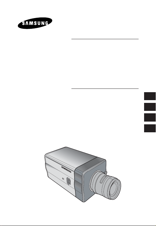
DIGITAL COLOR CAMERA
User’s guide
SCC-B2311
SCC-B2310
SCC-B2311P
SCC-B2011P
User’s guide
Manuel d’utilisation
Guía del usuario
ユーザー・ガイド
E
E
F
Es
J
Page 2

User’s guide
IMPORTANT SAFETY INSTRUCTIONS
1. Read these instructions.
2. Keep these Instructions.
3. Heed all warnings.
4. Follow all instructions.
E
5. Do not use this apparatus near water.
6. Clean only with dry cloth.
7. Do not block any ventilation openings. Install in accordance with the
manufacturer’s instructions.
8.
Do not install near any heat sources such as radiators, heat registers,
stoves, or other apparatus(including amplifiers) that produce heat.
9. Do not defeat the safety purpose of the polarized or grounding-type
plug. A polarized plug has two blades with one wider than the other.
A grounding type plug has two blades and a third grounding prong.
The wide blade or the third prong are provided for your safety. If the
provided plug does not fit into your outlet, consult an electrician for
replacement of the obsolete outlet.
10. Protect the power cord from being walked on or pinched particularly
at plugs, convenience receptacles, and the point where they exit
from the apparatus.
11. Only use attachment/accessories specified by the manufacturer.
12. Use only with the cart, stand, tripod, bracket, or table specified by
the manufacturer, or sold with the apparatus. When a cart is used,
use caution when moving the cart/apparatus combination to avoid
injury from tip-over.
13. Unplug this apparatus during lightning storms or when unused for
long periods of time.
Refer all servicing to qualified service personnel. Servicing is required
14.
when the apparatus has been damaged in any way, such as
powersupply cord or plug is damaged, liquid has been spilled or objects
have fallen into the apparatus, the apparatus has been exposed to rain
or moisture, does not operate normally, or has been dropped.
This device complies with Part 15 Rules. Operation is subject to
the following two conditions: (1) this deivce may not cause harmful
interference, and (2) the device must accept any interference received,
including interference that may cause undesired operation.
2
Page 3
User’s guide
Safety Precautions
The purpose of safety precautions is to prevent accidental injury or property
damage. Always observe all safety precautions.
▶ The precautions are divided into “Warnings” and “Cautions” as
distinguished below:
E
Warning
Ignoring this precaution
may result in death or
serious injury.
1. Be sure to use only the standard adapter which is specified in the
2. Check the external connection terminals first before connecting the power
3. Do not connect multiple cameras to a single adapter. (Exceeding the
4.Securely plug the power cord into the power receptacle.
(A loose connection may result in fire.)
Warnings
specification sheet. (Using any other adapter could cause fire, electrical
shock, or damage to the product).
source and signal wires.
capacity may cause abnormal heat generation or fire.)
Caution
Ignoring this precaution
may result in injury or
damage to property.
3
Page 4

User’s guide
5. When mounting the camera on a wall or ceiling, fasten it safely and
securely. (A falling camera may cause personal injury.)
6. Do not place conductive objects (e.g., screwdrivers, coins, and metal
things) or containers filled with water on top of the camera. (Serious injury
may result from fire, electrical shock, or falling objects.)
7. Do not install the unit in humid, dusty, or mines locations.
(Doing so may cause fire or electrical shock.)
8. If any unusual smells or smoke come from the unit, stop using the
E
product. In such case, immediately disconnect the power source and
contact the service center. (Continued use in such a condition may cause
fire or electrical shock.)
9. If this product fails to operate normally, contact the store of purchase or
your nearest service center. Never disassemble or modify this product in
any way. (Problems caused by unauthorized user disassembly or repairs
are not covered by your warranty.)
10. When cleaning, do not spray water directly onto parts of the product.
(Doing so may cause fire or electrical shock.) Gently wipe the surface
with a dry cloth. Never use detergents or chemical cleaners on the
product, as this may result in discoloration of surface or cause damage
to the finish.
11. To disconnect the apparatus from the mains, the plug must be pulled out
from the mains socket, therefore the mains plug shall be readily operable.
1. Do not drop objects on the product or apply strong shock to it. Keep
away from a location subject to excessive vibration or magnetic
interference.
2. Do not install in a location subject to high temperature, low temperature,
or high humidity. (Doing so may cause fire or electrical shock.)
3. Avoid a location which is exposed to direct sunlight, or near heat sources
such as heaters or radiators.
(Neglecting to do so may result in a risk of fire.)
4. If you want to relocate the already installed product, be sure to turn off
the power before moving or reinstalling it.
5. Install in a well-ventilated location.
6. Remove the power plug from the outlet when there is a lightning storm.
(Neglecting to do so may cause fire or damage to the product.)
4
Cautions
Page 5

Table Of Contents
User’s guide
Chapter 1 Overview ..................................................... 5
Chapter 2 Features ...................................................... 6
Chapter 3 Installation ................................................... 8
Package.................................................... 8
Installation and Use Instructions .............. 9
Connect the auto iris lens connector....... 10
Install the lens........................................... 11
Adjust the selection switch...................... 12
Adjust the back focus.............................. 13
Connect the cables and
check the operation ................................. 15
Chapter 4 Parts & Description..................................... 17
Specifications ............................................. 24
E
5
Page 6

User’s guide
[Chapter 1] Overview
The DAYNIGHT camera is a low-illumination device that
Operates in color mode while illumination is above certain
level and in operates in B/W mode in low contrast scenes
therefore enhancing the color sensitivity. It is a high-resolution
E
camera that has implemented the horizontal resolution of 540
lines by taking advantage of the Digital Signal Processing
and OLPF technologies. (SCC-B2311(P), SCC-B2011P)
[DAYNIGHT]
A feature that switches to B/W from color mode at less than a certain
illumination to enhance the sensitivity.
※ In mechanical fluorescent lightning conditions, you can
experience so-called “color rolling” if you have installed
the manual iris lens on the camera and positioned the
function switch from ELC to ON. In this case, connect the
camera to the power source (AC) and position the L/L
switch on the rear panel to ON. (NTSC: 60Hz, PAL: 50Hz)
- What is Color Rolling?
This occurs because the mechanical fluorescent lightning blinks
from power frequencies, where the color temperature input to
the camera is not certain so the color on the screen changes
irregularly (red, blue, yellow, etc).
→
This problem can be solved by using the Line Lock
function or the Auto Iris Lens.
6
Page 7

User’s guide
[Chapter 2] Features
High Color Sensitivity
The camera adopts the latest 1/3” super-HAD IT CCD to get the
benefit of high color sensitivity.
Resolution
Introduces Full Digital Image Processing from the digital signal
technology to implement a high-resolution image.
Excellent Back Light Compensation
This will guarantee a sharp image by compensating for the back
light even if the sunlight or bright lightening reflects against the
subject.
Digital Power Synchronization
Adopts the full digital line lock system to enable you to adjust
the vertical synchronization of the camera, an enhancement of
manipulation and reliability.
Sense Up
Uses the field storage system to provide a sharp image; even in
low contrast scenes (dark scenes).
DAYNIGHT
Operates in color mode at higher than a certain illumination while
operating in B/W mode to enhance the color sensitivity of the subject in
low contrast scenes.
E
7
Page 8

User’s guide
DNR(Digital Noise Reduction)
Uses the full digital system to effectively remove the random noise
on the image. Especially, it’s useful to use LSS (Sense-Up).
E
Dynamic CCD Defect Compensation
Uses advanced technology to compensate CCD defects in any
mode, to give clear, sharp and noise-free images, even in low
contrast scenes.
8
Page 9
User’s guide
[Chapter 3] Installation
In this chapter, we will provide you with general instructions for
product installation and preferred places as well as considerations
before installation.
Now, let’s install the camera and connect necessary cables.
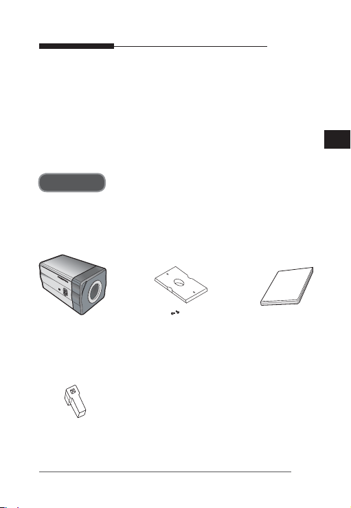
Package
You must check that all the components and accessories listed
below are included in the product package.
E
Camera
Auto Iris Lens
Connector
Camera Holder
(Mount Adaptor)
screw x2
User’s guide
9
Page 10

Installation and Use Instructions
① There is no user serviceable part inside. So do never
E
disassemble the product.
② Always take caution in handling the product. Do not
put force on or shake the product and make sure to
follow the instructions to avoid possible damage to the
product from an accident.
③ Do not expose it to rain or moisture and keep away
from wet places.
④ Do not use strong abrasives to clean up camera body
and only use a dry cloth to dirt off.
⑤ Do not expose it to direct sunlight and keep it cool.
Otherwise, it can cause a malfunction or an error.
User’s guide
10
Page 11
User’s guide
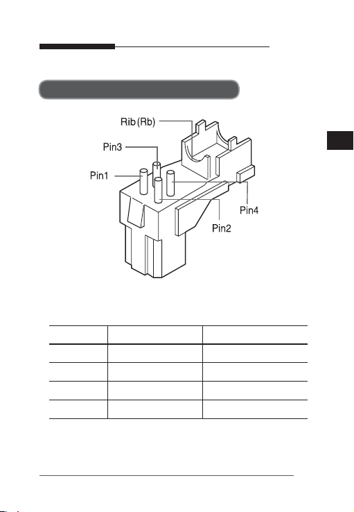
Connect the auto iris lens connector
Remove the sheath round the iris control cable and connect it to
each of the auto iris lens connector as described below.
Pin Number DC Control Type Video Control Type
1 Damp(–) Voltage (+12V)
2 Damp(+) Not Used
3 Drive(+) Video Signal
4 Drive(–) Ground
E
11
Page 12
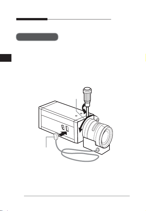
Install the lens
Loosen the single screw on the adjustable ring of the flange
back by turning it anti-clockwise and turn the ring in the “C”
E
direction (anti-clockwise) to the end. Otherwise, it can cause
damage to the internal image sensor or the lens when you
install the lens on the camera.
C direction
Iris Control Cable
User’s guide
12
Page 13
User’s guide
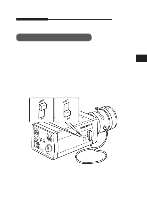
Position the selection switch
You must position the lens selection switch on the side of the
camera, depending on the lens type. If the installed lens is of
DC control type, position the selection switch to “DC” and, for
video control type, switch it to “VIDEO”.
E
13
Page 14

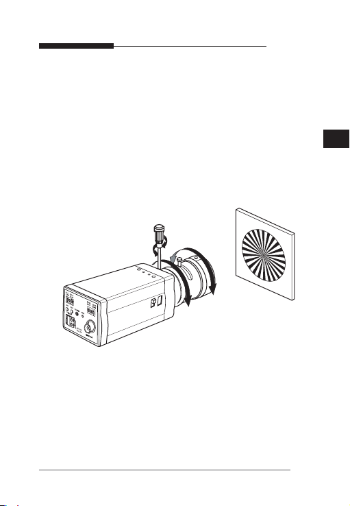
Adjust the back focus
The back focus of a camera is predefined by the factory default.
However, some models are out of focus depending on the lens
E
type. If your camera is out of focus, follow the instructions below
to adjust the back focus. The following is the procedure used to
set the proper back focus point in fixed focus lenses.
Lens without zooming feature
① Capture a sharp subject (with a grid pattern) more than 10m
apart and adjust the focus ring to the infinity (∞).
② Adjust the adjustable ring of the flange back so that you can
capture the sharpest image.
③ Fasten the screw of the adjustable ring of the flange back.
Lens with zooming feature
① Capture a sharp subject (with a grid pattern) 3-5m apart and
adjust the zoom in the TELE (zooming) direction as possible
and also adjust the focus ring so that you can capture the
sharpest image.
② Adjust the zoom in the WIDE direction as possible and
turn the adjustable ring of the flange back so that you can
capture the sharpest image.
③ Repeat ① and ② above 2-3 times to match the focus from
the ZOOM TELE side with that from the ZOOM WIDE side.
User’s guide
14
Page 15
User’s guide
④ Fasten the screw of the adjustable ring of the flange back.
- If you darken the image before adjusting the focus by
attaching the ND filter to the front of the lens, you can get
a sharper focus.
E
15
Page 16
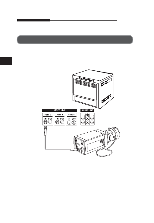
Connect the cables and check the operation
1. Connect one end of the BNC cable to the VIDEO OUT port
of the monitor.
E
2. Connect the other end of the BNC cable to the VIDEO In port.
IN
VIDEO IN Terminal on
the rear of moniter
BNC Cable
VIDEO OUT Terminal
3. Connect the camera to the power adaptor. Use a slotted
flat (-) screwdriver to connect one end of the two-line power
adaptor to the DC/AC IN port of the camera.
(GND: marked with a white line on the cable)
- You can plug in to a power outlet regardless of the polarity
for both AC 24V and DC 12V adaptor.
OUT
User’s guide
16
Page 17

User’s guide
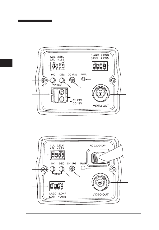
AC24V/DC12V models (SCC-B2311, B2310, B2311P)
AC220V models (SCC-B2011P)
E
17
Page 18
User’s guide
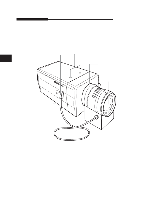
[chapter 4] Parts & Description
① Mount Adaptor Holes
⑥ Auto Iris Lens
④ Flange Back
② Auto Iris Lens
Control Cable
E
⑤ ALC Lens Selection
Switch
③ Auto Iris Lens
Connector
① Mount Adaptor Holes
Used to fix the mount adaptor with a screw if you want to
mount the camera on the bracket.
② Auto Iris Lens (Optional)
A lens to be installed on the camera
If the camera gets dirty on the surface of the lens, apply ethanol to
the provided tissue or a dry cloth and wipe it out.
18
Adjustable Ring
Page 19

User’s guide
③ Auto Iris Lens Connector
Provides power source and control/ video/DC signal with iris
lens that are required to control the iris of the lens.
④ Flange Back Adjustable Ring
Used to adjust the back focus of the camera.
⑤ ALC Lens Selection Switch
Switch for selecting the type of the lens on the camera.
- DC : position the switch to “DC” if the auto iris lens that
requires the DC control signal is installed on your
camera.
- VIDEO : position the switch to “VIDEO” if the auto iris lens
that requires the video control signal is installed on
your camera.
⑥ Auto Iris Lens Control Cable
Transfers the control signal from the camera to the iris lens.
E
19
Page 20
User’s guide
AC24V/DC12V Models (SCC-B2311, B2310, B2311P)
E
⑤
③
①
AC220V Models (SCC-B2011P)
⑤
③
⑥
20
⑥
②
⑦
④
②
④
⑦
⑧
①
⑧
Page 21
User’s guide
① Power Port
Port that is connected to the power (adaptor) cable.
- For SCC-B2311, SCC-B2310 and SCC-2311P
Connects to AC 24V or DC 12V.
- For SCC-B2011P
Connects to AC 230V.
② Power Indication LED
If properly supplied with power, the LED turns on.
③ Vertical Synchronization Phasing Switch (Left)
Used to adjust the vertical synchronization phasing. If pressed,
the vertical synchronization moves to the left.
④ Vertical Synchronization Phasing Switch (Right)
Used to adjust the vertical synchronization phasing. If pressed,
the vertical synchronization moves to the right.
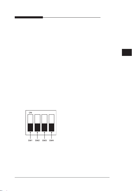
⑤ FUNCTION SWITCH-1
1. L/L
2. ELC
3. FL(Flickerless)
4. LSS
1) SW1 (L/L) :
If set to OFF, it operates in the internal synchronization
mode and if set to ON, it operates in the power
synchronization mode. If multiple cameras are connected
to such as a sequential switcher in auto switch mode, the
E
21
Page 22

User’s guide
camera in the internal sync mode occurs a skip every time
it moves to other scene. However, this can be solved by
positioning the L/L switch to ON and using the level bar to
E
adjust the vertical sync phasing.
- If your camera uses DC 12V for power source, it operates
in the internal mode regardless of the position (On/Off) of
the L/L switch.
2) SW2(ELC) :
Use this for the manual iris lens. If set to ON, the electronic
shutter speed varies between 1/60 and 1/120,000 second
to keep the screen brightness proper. However, you must
position this switch to OFF if you are using the auto iris
lens (DC or Video control type). Because, in this mode, the
camera can show the color rolling effect when operating
under the mechanical fluorescent lightning. If this happens,
apply the AC power and set the SW1 (L/L) to ON. (NTSC:
60Hz, PAL: 50Hz)
3) SW3 (FL) :
It is an anti-flicker system in 50Hz areas for NTSC and,
in 60Hz areas for PAL that prevents the flickering of the
image due to mismatch between the vertical sync frequency
and the on-off frequency of the lightning. If set to ON, the
electronic shutter speed stays at either 1/100sec (NTSC) or
1/120sec (PAL).
※Note : If SW2 (ELC) is set to ON, the anti-flicker system
does not work even if SW3 is positioned to ON.
22
Page 23

User’s guide
4) SW4(LSS) :
It is a Sense-Up function that keeps storing the image field
into memory to remove the random noise on the image and
increase the brightness and the contrast ratio. If set to ON,
the camera automatically switches to a maximum of 128
times of storage mode for sharper image.
⑥ FUNCTION SWITCH-2
1. AGC
2. DNR
3. D/N
4. AWB
1) SW1(AGC)
This switch turns on or off the AGC (Auto Gain Control)
function of the camera. If set to ON, the AGC automatically
increases the gain in a low contrast scene of which the iris
couldn’t control the brightness.
2) SW2(DNR)
This switch reduces the random noise on the image. In
particular, this is more effective when the SW4 on the
function switch -1 is set to ON.
3) SW3(D/N)
This indicates the DAY & NIGHT function. If set to ON, the
camera outputs a color image during the daytime and enhances
the color sensitivity of the subject in a low contrast scene,
especially at night by turning off the IR cutoff filter.
23
E
Page 24

User’s guide
※Note : If SW1 (AGC) is set to OFF, the Day & Night function
does not work even if SW3 is positioned to ON.
E
4) SW4(AWB)
If set to ON, it automatically adjusts the image color
according to the temperature change of the lightning color.
Under a very irregular lightning condition (such as car
headlight), if set to ON, it captures a subject normally (white)
and if set to OFF, it remembers the then normal color temp
to operate at a certain white balance level. Note that AWB
can cause an error in the following conditions. First, if a big
subject of a uniform color with a high saturation exists in the
center of the screen or if few part of the image is in white.
Second, if the lightning is made of special material like
sodium.
⑦ DC IRIS Level Bar
If the ALC lens selection switch is set to DC, use a screwdriver
to adjust the iris level on this bar.
※Note : -
⑧ Video Out Port
Connected to the Video Out port of a monitor. The video signal
is output via this port.
24
The IRIS range of the DC lens is about between 80IRE and
120IRE. In other words, the DC lens adopts a variable range
limitation system, rather than IRIS Full Open/Close system.
-
Depending on the type of the lens used that allows setting the
value below 75 IRE may cause IRIS hunting. Therefore, make sure
that the range is set to an appropriate level (higher than 80 IRE).
Page 25

Specifications
【 SCC-B2311, SCC-B2310 】
Item Description
Product Type Surveillance Camera
Broadcasting System NTSC STANDARD SYSTEM
Imaging Device 1/3”IT, S-HAD-CCD
Number of Effective
Pixels
Scanning 525 Line, 2:1 interlace
Line Frequency
Synchronous Mode
Horizontal Resolution
S/N Ratio Approx. 50dB
Minimum Subject
Illumination
ALC/ELC
FL(FLICKERLESS) OFF/ON
LSS(SenseUP) OFF/ON (Auto x 128)
DNR OFF/ON
DN (DAYNIGHT) OFF/ON (Auto)
Color Temp ATW(Auto White Balance)/AWC
BLC (Back Light Compensation)
AGC OFF/ON
Signal Out
Power AC24V ±10%(60Hz±0.3Hz), DC12V+10%~-5%
Power Consumption Approx. 3.0 Watts
Temperature -10˚C ~ +50˚C
Moist ~90%
Dimension 65 (W)x 55 (H)x 138 (D)mm(BNC included)
Weight 440 g
SCC-B2311: 768(H) x 494(V)
SCC-B2310: 510(H) x 492(V)
INTERNAL : 15,734Hz(H) 59.94 Hz(V)
LINELOCK : 15,750Hz(H) 60 Hz(V)
INTERNAL
LINE LOCK(AC 24V)
SCC-B2311 : 540 TV Lines
SCC-B2310 : 330 TV Lines
SCC-B2311 : 0.12 Lux (F1.2, 15 IRE, Sense-up off)
0.0009 Lux (F1.2, 15 IRE, Sense-up x 128)
SCC-B2310 : 0.06 Lux (F1.2, 15 IRE, Sense-up off)
0.0005 Lux (F1.2, 15 IRE, Sense-up x 128)
ALC
DC IRIS LENS
VIDEO LENS
ELC
Electronic Shutter Iris(max. 1/120Ksec)
ON
COMPOSITE VIDEO OUT
1V p_p 75Ω / BNC
User’s guide
E
25
Page 26

Specifications
【 SCC-B2311P, SCC-B2011P 】
Item Description
Product Type Surveillance Camera
Broadcasting System PAL STANDARD SYSTEM
E
Imaging Device 1/3”IT, S-HAD-CCD
Number of Effective Pixels
Scanning 625 Line, 2:1 interlace
Line Frequency
Synchronous Mode
Horizontal Resolution 540 TV Lines
S/N Ratio Approx. 50dB
Minimum Subject
Illumination
ALC/ELC
FL(FLICKERLESS) OFF/ON
LSS(SenseUP) OFF/ON (Auto x 128)
DNR OFF/ON
DN (DAYNIGHT) OFF/ON (Auto)
Color Temp ATW(Auto White Balance)/AWC
BLC (Back Light Compensation)
AGC OFF/ON
Signal Out
Power
Power Consumption
Temperature -10˚C ~ +50˚C
Moist ~90%
Dimension 65 (W)x 55 (H)x 138 (D)mm(BNC included)
Weight
26
752(H) x 582(V)
INTERNAL : 15,625Hz(H) 50 Hz(V)
LINE LOCK : 15,625Hz(H) 50 Hz(V)
INTERNAL
LINE LOCK(AC 24V)
0.12 Lux (F1.2, 15 IRE, Sense-up off)
0.0009 Lux (F1.2, 15 IRE, Sense-up x 128)
ALC
DC IRIS LENS
VIDEO LENS
ELC
Electronic Shutter Iris (max. 1/120K sec)
ON
COMPOSITE VIDEO OUT
1V p_p 75Ω/BNC
SCC-B2311P : AC24V ±10%(50Hz±0.3Hz), DC12V+10%~-5%
SCC-B2011P : AC220V~AC240V(50Hz±0.3Hz)
SCC-B2311P: approx. 3.0 Watts
SCC-B2011P: approx. 3.5 Watts
SCC-B2311P : 440 g
SCC-B2011P : 550 g
User’s guide
Page 27

E
Part No.: AB68-00613A
Page 28
Veuillez lire attentivement les ‘précautions de
sécurité’ de ce manuel afin d’assurer une utilisation et
un fonctionnement corrects de l’appareil.
CAMERA NUMERIQUE COULEUR
Manuel d’utilisation
SCC-B2311
SCC-B2310
SCC-B2311P
SCC-B2011P
Manuel d’utilisation
F
Page 29
Manuel d’utilisation
Précautions de sécurité
Les précautions de sécurité sont des mesures à prendre pour
éviter toute blessure accidentelle ou un dommage sur l’appareil.
Veuillez toujours respecter toutes les précautions.
▶ Ces précautions comportent les mention ‘Avertissement’
et ‘Attention’ comme indiqué ci-dessous :
F
Avertissement
Ignorer cette précaution peut
provoquer une blessure
sérieuse voir mortelle.
Attention
Ignorer cette précaution peut provoquer
une blessure ou un endommagement
de l’appareil.
Avertissement
1. IN’utilisez que l’adaptateur standard précisé sur la feuille de
spécifications. (L’utilisation d’un adaptateur d’un autre type peut
provoquer un incendie, un choc électrique ou un dommage sur
l’appareil.)
2. IVérifiez d’abord les terminaux de connexions externes avant de
connecter le cordon d’alimentation et les câbles signaux.
3. INe connectez pas de multiples caméras à un seul adaptateur.
(Une capacité excessive peut provoquer un échauffement
anormal ou un incendie.)
4. Branchez solidement le cordon d’alimentation sur le secteur.
(Une connexion lâche peut provoquer un incendie.)
5. Lors d’une installation mural ou au plafond, fixez solidement la
caméra en toute sécurité. (Une chute de la caméra peut
provoquer une blessure personnelle.)
2
Page 30

Manuel d’utilisation
6. Ne placez pas d’objets conducteurs (tournevis, pièces de monnaie
ou objets métalliques) ou des conteneurs remplis d’eau au-dessus
de la caméra. (Des blessures sérieuses peuvent être provoquées
par un incendie, un choc électrique ou une chute d’objets.)
N’installez pas l’appareil dans des endroits humides, poussiéreux ou couverts
7.
de suie. (Ceci peut provoquer un incendie ou un choc électrique.)
8. En cas d’émission d’odeur ou de fumée inhabituelles hors
de l’appareil, arrêtez immédiatement son fonctionnement et
débranchez le cordon d’alimentation. Contactez ensuite le centre
de service. (Une utilisation en continu dans ces conditions peut
provoquer un incendie ou un choc électrique.)
9. Si l’appareil ne fonctionne pas correctement, contactez le centre
d’achat ou votre centre de service le plus proche. En aucun cas,
vous ne devez démonter ni modifier l’appareil. (Les problèmes
causés par le démontage ou la réparation par une personne non
autorisée ne sont pas couverts par votre garantie.)
10. Lors d’un nettoyage, évitez de vaporiser de l’eau directement
sur les parties de l’appareil. (Ceci peut provoquer un incendie
ou un choc électrique). Essuyez doucement la surface avec un
tissu sec. N’appliquez jamais de détergent ou de nettoyant
chimique sur l’appareil, car ceci peut provoquer une décoloration
endommager la surface.
11. Pour débrancher l’appareil, il convient de retirer la fiche de la
prise murale afin que celle-ci soit facilement accessible.
Attention
1. Ne faites pas tomber d’objet sur l’appareil et ne lui donnez pas de
choc. L’emplacement de l’appareil doit être éloigné des
interférences magnétiques ou de vibrations excessives.
2. N’installez pas l’appareil dans un endroit humide ou à une
température trop haute ou trop basse. (Ceci peut provoquer un
incendie ou un choc électrique.)
3. Evitez un emplacement exposé aux rayonnements direct du soleil
ou proche des sources de chaleur telles que les radiateurs.
(Ne pas respecter ceci risque de provoquer un incendie.)
4. Si vous voulez déplacer un appareil déjà installé, n’oubliez pas de
le mettre hors tension avant le déplacement et la réinstallation.
5. Installez l’appareil dans un endroit bien aéré.
6. Retirez la prise de courant lors d’un orage accompagné d’éclairs.
(Ne pas respecter ceci risque de provoquer un incendie ou un
dommage sur l’appareil.)
3
F
Page 31

Table des matières
Chapitre 1 Présentation............................................. 5
F
Chapitre 2 Fonctionnalités......................................... 6
Chapitre 3 Installation................................................ 8
Contenu................................................. 8
Installation et consignes d’utilisation ..... 9
Branchement du connecteur de
l’objectif à diaphragme automatique...... 10
Installation de l’objectif .......................... 11
Branchement des câbles et vérification
du fonctionnement ................................ 15
Chapitre 4 Eléments et description............................ 17
Caractéristiques techniques..................... 24
Réglage du commutateur de sélection
Réglage de la focale minimale du zoom
Manuel d’utilisation
........ 12
...... 13
4
Page 32

Manuel d’utilisation
[Chapitre 1] Présentation
La caméra DAYNIGHT est un appareil conçu pour fonctionner dans des
endroits à faible luminosité. Elle fonctionne en mode couleur au-delà d’un
certain niveau de luminosité et, lorsque le contraste est faible, elle passe
en mode N/B pour accroître la sensibilité d’identification du sujet. Cette
caméra haute résolution utilise une résolution horizontale de 540 lignes
et fait appel à la technologie du traitement numérique du signal et aux
technologies OLPF (filtre passe-bas optique).(SCC-B2311(P), SCC-B2011P)
[DAYNIGHT]
Fonction permettant de passer du mode couleur au mode N/B en
deçà d’un certain seuil de luminosité afin d’accroître la sensibilité de
l’appareil.
※
Dans des conditions d’éclairage fluorescent mécanique, il se peut
que vous soyez confronté à une "commutation des couleurs"
si l’objectif du diaphragme est en mode manuel et si le
commutateur de fonction ELC (Contrôle électronique de
lumière) est activé. Dans ce cas, branchez la caméra sur la
source d’alimentation (CA) et activez le commutateur L/L
(verrouillage de la ligne) situé sur le panneau arrière.
(NTSC : 60 Hz, PAL : 50 Hz)
- Qu’est-ce que la "commutation des couleurs" ?
Ce phénomène se produit lorsque l’éclairage fluorescent mécanique
est émit à des fréquences irrégulières là où la température de la
couleur dans la caméra varie, provoquant ainsi des changements
de couleurs irréguliers à l’écran (rouge, bleu, jaune, etc.).
→ Ce problème peut être résolu grâce à la fonction Line
Lock (Verrouillage de la ligne) ou Auto Iris Lens (Objectif à
diaphragme automatique).
F
5
Page 33

Manuel d’utilisation
[Chapitre 2] Fonctionnalités
Haute sensibilité chromatique
La caméra est équipée du dernier capteur CCD 1/3”
super-HAD IT qui permet d’accroître considérablement la
sensibilité chromatique.
F
Résolution
Cette caméra fait appel à la technique du Traitement
numérique complet d’image (Full Digital Image Processing)
issue de la technologie du signal numérique afin d’obtenir
des images haute résolution.
Compensation de contre-jour supérieure
Cette fonction permet d’obtenir une image nette en
compensant l’effet du contre-jour, même lorsque le sujet
est exposé à la lumière du soleil ou une autre source
lumineuse intense.
Synchronisation numérique
Fait appel au système Line Lock (Verrouillage de ligne)
numérique complet pour vous permettre de régler la
synchronisation verticale de la caméra et d’améliorer la
manipulation de l’appareil ainsi que sa fiabilité.
Augmentation électronique de la sensibilité
Cette fonction fait appel à un système de stockage des
trames pour fournir une image nette, même dans les
endroits à faible contraste (scène sombre).
6
Page 34

Manuel d’utilisation
DAYNIGHT
L’appareil fonctionne en mode couleur lorsque la luminosité dépasse
un certain seuil, mais en mode N/B lorsque le contraste est faible afin
d’accroître la sensibilité du sujet.
DNR (Réduction du bruit numérique)
F
Cette fonction utilise le système numérique entier afin
de supprimer le bruit aléatoire de l’image. Elle est
particulièrement utile lorsque vous souhaitez activer la
fonction LSS (Basse vitesse d’obturation) (Augmentation
électronique de la sensibilité).
Compensation dynamique de défaut CCD
Cette fonction fait appel à la technologie de pointe de
compensation des défauts CCD dans tous les modes afin
d’obtenir une image, claire, nette et dépourvue de bruit,
même dans les endroits à faible contraste.
7
Page 35

Manuel d’utilisation
[Chapitre 3] Installation
Dans ce chapitre, des informations d’ordre général concernant
l’installation du produit et les endroits préconisés pour le
montage vous seront fournies ainsi que quelques remarques
utiles avant installation.
A présent, installez la caméra et branchez les câbles requis.
F
Contenu
Nous vous conseillons de vérifier que toutes les pièces et
tous les accessoires énumérés ci-dessous sont bien inclus
dans la boîte du produit.
Caméra
Connecteur d’objectif
à diaphragme
automatique
8
Vis (x2) du support de
caméra (adaptateur de
fixation)
Manuel
d’utilisation
Page 36

Manuel d’utilisation
Installation et consignes d’utilisation
① Ce produit ne contient aucune pièce pouvant être
réparée par l’utilisateur. L’appareil ne doit donc jamais
être démonté.
② Manipulez toujours l’appareil avec précaution.
N’exercez jamais de pression excessive dessus
et évitez de le secouer. Assurez-vous de suivre
les instructions afin d’éviter tout endommagement
accidentel.
③ Ne l’exposez pas à la pluie ou à toute forme
d’humidité et conservez-le dans un endroit sec.
④ N’utilisez pas de produit abrasif pour nettoyer le boîtier
; uniquement un chiffon sec.
⑤ N’exposez pas l’appareil à la lumière directe du soleil
et gardez-le à température ambiante. Dans le cas
contraire, cela pourrait provoquer une erreur ou un
dysfonctionnement.
F
9
Page 37

Manuel d’utilisation
Branchement du connecteur de l’objectif à diaphragme automatique
F
Retirez la gaine protégeant le câble de commande du
diaphragme et branchez-le sur chaque connecteur de l’objectif
à diaphragme automatique comme indiqué ci-dessous.
Numéro Pin
Type de commande CC Type de commande vidéo
1 Humide (-) Tension (+12 V)
2 Humide (+) Non utilisé
3 Lecteur (+) Signal vidéo
4 Lecteur (-) Mise à la terre
10
Page 38

Manuel d’utilisation
Installation de l’objectif
Desserrez l’unique vis située sur l’anneau de réglage au
dos de l’embase en la tournant dans le sens inverse des
aiguilles d’une montre et tournez l’anneau dans le sens
"C" (inverse des aiguilles d’une montre) au maximum.
Dans le cas contraire, vous risqueriez d’endommager le
capteur d’image interne ou l’objectif lorsque vous installez
ce dernier sur la caméra.
Sens C
Câble de
commande du
diaphragme
F
11
Page 39

Positionnement du commutateur de sélection
Positionnez le commutateur de sélection de l’objectif
situé sur le côté de la caméra selon le type d’objectif. S’il
s’agit d’un objectif de type commande CC, positionnez
le commutateur de sélection sur "CC" ; s’il s’agit d’une
F
commande vidéo, sur "VIDEO".
Manuel d’utilisation
12
Page 40

Manuel d’utilisation
Réglage de la focale minimale du zoom
La focale minimale d’une caméra est définie par défaut
en usine. Néanmoins, certains modèles ne peuvent
effectuer la mise en point en raison du type d’objectif.
Si la caméra n’effectue pas la mise au point, suivez les
instructions ci-dessous pour régler la focale minimale
du zoom. Les informations suivantes vous indiquent la
procédure à suivre pour régler la focale minimale de
l’objectif du zoom fixe.
Objectif sans la fonction zoom
① Effectuez un plan d’un sujet net (avec un motif
quadrillé) à plus de 10 m de distance et réglez la
bague de mise au point sur l’infini (∞).
② Réglez la bague située au dos de l’embase pour
pouvoir cadrer l’image la plus nette possible.
③ Serrez la vis de la bague de réglage au dos de
l’embase.
Objectif avec la fonction zoom
① Effectuez un plan d’un sujet net (avec un motif
quadrillé) entre 3 et 5 m de distance et réglez le zoom
sur TELE (TELE) (zoom). Réglez également la bague
de mise au point de manière à obtenir l’image la plus
nette possible.
F
13
Page 41

② Réglez le zoom sur WIDE (LARGE) et tournez la
bague de réglage du dos de l’embase de manière à
prendre l’image la plus nette possible.
③ Répétez les étapes ① et ② ci-dessus 2 à 3 fois afin
F
que les mises au point ZOOM TELE (ZOOM TELE)
et ZOOM WIDE (ZOOM LARGE) correspondent à la
mise au point ZOOM WIDE (ZOOM LARGE).
④ Serrez la vis de la bague de réglage située au dos de
l’embase.
- Si vous assombrissez l’image avant de régler la mise
au point en reliant le filtre ND à l’avant de l’objectif,
vous obtenez une mise au point plus nette.
Manuel d’utilisation
14
Page 42

Manuel d’utilisation
Branchement des câbles et vérification du fonctionnement
1. Branchez une extrémité du câble BNC au port VIDEO
OUT (SORTIE VIDEO) de l’écran.
2. Branchez l’autre extrémité du câble BNC au port
VIDEO IN (ENTREE VIDEO).
F
LIGNE VIDEO
Borne VIDEO IN (ENTREE
VIDEO) à l’arrière de l’écran
Câble BNC
Borne VIDEO OUT (SORTIE VIDEO)
LIGNE AUDIO
IN
OUT
3. Branchez la caméra sur l’adaptateur. Servez-vous d’un tournevis
à fente (-) pour relier l’une des extrémités de l’adaptateur à deux
lignes au port DC/AC IN (ENTREE CC/CA) de la caméra.
(GND : indiqué par une ligne blanche sur le câble)
- Vous pouvez effectuer le branchement sur la prise secteur
sans tenir compte de la polarité des connecteurs AC 24V (CA
24 V) et DC 12V (CC 12 V) de l’adaptateur.
15
Page 43

Modèles CA24V/CC12V (SCC-B2311, B2310, B2311P)
F
Modèles CA 220V (SCC-B2011P)
Manuel d’utilisation
16
Page 44

Manuel d’utilisation
[chapitre 4] Eléments et description
③ Connecteur de l’objectif à
diaphragme automatique
⑤ Commutateur de
sélection de l’objectif
ALC (contrôle
automatique de niveau)
① Trous de fixation de l’adaptateur
④ Bague de réglage du dos de
l’embase
② Objectif à diaphragme
automatique
⑥ Câble de commande de l’objectif
du diaphragme automatique
① Trous de fixation de l’adaptateur
Permettent de fixer l’adaptateur à l’aide d’une vis si vous
souhaitez monter la caméra sur un support.
② Objectif à diaphragme automatique (en option)
Consiste en un objectif devant être installé sur la caméra
Pour nettoyer la surface de l’objectif, essuyez-la avec un
chiffon fourni ou n’importe quel chiffon sec imbibé d’alcool éthylique.
17
F
Page 45

③ Connecteur d’objectif à diaphragme automatique
Permet de fournir au diaphragme automatique
l’alimentation et les signaux de commande/vidéo/CC
nécessaires afin de contrôler le diaphragme de l’objectif.
④ Bague de réglage du dos de l’embase
Permet de régler la distance focale de la caméra.
F
⑤ Commutateur de sélection de l’objectif ALC (contrôle
automatique de niveau)
Commutateur permettant de sélectionner le type
d’objectif à installer sur la caméra
- CC : réglez le commutateur sur cette position si
l’objectif à diaphragme automatique nécessitant un
signal de commande CC est installé sur la caméra.
- VIDEO : réglez le commutateur sur cette position si
l’objectif à diaphragme automatique nécessitant un
signal de commande Vidéo est installé sur la caméra.
⑥ Câble de commande de l’objectif du diaphragme
automatique
Permet de transférer le signal de commande de la
caméra vers l’objectif à diaphragme.
Manuel d’utilisation
18
Page 46

Manuel d’utilisation
Modèles CA24V/CC12V (SCC-B2311, B2310, B2311P)
⑤
③
⑦
①
④
Modèles CA 220V (SCC-B2011P)
⑤
③
④
⑦
⑥
⑥
F
②
⑧
①
②
⑧
19
Page 47

① Port d’alimentation
Port connecté au câble d’alimentation (adaptateur).
-
Pour les modèles SCC-B2311, SCC-B2310 et SCC-B2311P
Se branche sur CA 24V ou CC 12V
- Pour le modèle SCC-B2011P
Se branche sur CA 230 V.
② Témoin DEL d’alimentation
Lorsque l’appareil est correctement alimenté en courant,
F
la DEL s’allume.
③ Commutateur de mise en phase de la synchronisation
verticale (gauche)
Permet de régler la mise en phase de la synchronisation
verticale. Si vous appuyez sur ce commutateur, la
synchronisation se déplace sur la gauche.
④ Commutateur de mise en phase de la synchronisation
verticale (droite)
Permet de régler la mise en phase de la synchronisation
verticale. Si vous appuyez sur ce commutateur, la
synchronisation se déplace sur la droite.
⑤ COMMUTATEUR DE FONCTION 1
1. L/L (verrouillage de la ligne)
2. ELC (contrôle électronique de lumière)
3. FL(sans papillotement)
4. LSS (basse vitesse d’obturation)
1) SW1 (L/L) (verrouillage de ligne) :
Lorsqu’elle est désactivée, cette option fonctionne en
mode synchronisation interne. Si elle est désactivée,
elle fonctionne en mode synchronisation externe. Si
plusieurs caméras sont branchées sur un sélecteur
20
Manuel d’utilisation
Page 48

Manuel d’utilisation
séquentiel en mode commutation automatique, la caméra
fonctionnant en mode sync interne saute chaque fois
qu’elle change de scène. Toutefois, ce problème peut
être résolu en activant le commutateur L/L (verrouillage
de la ligne) et en utilisant la barre de niveau pour régler la
mise en phase de la sync verticale.
- Si votre caméra est alimentée sous CC 12 V, elle
fonctionne en mode interne quelle que soit la
position du commutateur L/L (activé/désactivé).
2) SW2 (ELC) (contrôle électronique de lumière) :
Utilisez cette fonction pour l’objectif à diaphragme manuel.
Si elle est activée, la vitesse de l’obturateur électronique
varie entre 1/60 et 1/120 000 secondes afin de conserver
une luminosité adéquate à l’écran. Toutefois, vous devez
désactiver le commutateur si vous utilisez l’objectif à
diaphragme automatique (type CC ou commande vidéo).
En effet, dans ce mode, un phénomène de commutation
de couleur peut survenir lorsque l’appareil est utilisé sous
un éclairage mécanique fluorescent. Si cela se produit,
passez en alimentation CA et activez la fonction SW1
(L/L). (NTSC : 60 Hz, PAL : 50 Hz)
3) SW3 (FL) :
Il s’agit d’un dispositif de protection contre les
papillotements dans les zones à 50 Hz pour un système
NTSC et à 60 Hz pour le système PAL qui empêche les
papillotements de l’image dus à une différence entre la
fréquence de sync verticale et la fréquence on-off de la
luminosité. Lorsque ce commutateur est activé, la vitesse
de l’obturateur électronique stagne à 1/100 s. (NTSC) ou
1/120 s. (PAL).
※Remarque : Si SW2 (ELC) est activé, le système de
protection contre les papillotements ne fonctionne
pas même si la fonction SW3 est activée.
21
F
Page 49

4) SW4 (LSS) (faible vitesse d’obturation) :
Il s’agit d’une fonction d’augmentation électronique de
la sensibilité qui mémorise les champs d’une image
afin d’en retirer les bruits de fond et d’augmenter la
luminosité et le rapport de contraste. Lorsqu’elle est
activée, la caméra passe automatiquement en mode de
stockage 128 (maxi.) afin d’obtenir une image plus nette.
F
⑥ COMMUTATEUR DE FONCTION 2
1.
AGC (CONTROLE AUTOMATIQUE DU GAIN)
2.
DNR (REDUCTION DU BRUIT NUMERIQUE)
3. D/N (JOUR/NUIT)
4.
AWB (BALANCE DES BLANCS AUTOMATIQUE)
1) SW1 (AGC) (CONTROLE AUTOMATIQUE DU GAIN)
Ce commutateur permet d’activer ou de désactiver
la fonction AGC (contrôle automatique du gain).
Lorsqu’elle est activée, le gain est automatiquement
augmenté dans une scène à faible contraste pour
laquelle le diaphragme ne peut contrôler la luminosité.
2) SW2 (DNR) (REDUCTION DU BRUIT NUMERIQUE)
Ce commutateur permet de réduire les bruits de fond
de l’image. Cette fonction est encore plus efficace
lorsque l’option SW4 du commutateur de fonction 1
est activée.
3) SW3 (D/N) (JOUR/NUIT)
Renvoie à la fonction DAY & NIGHT (JOUR ET NUIT).
Si elle est activée, la caméra produit une image en
couleur le jour et augmente la sensibilité de la couleur
d’un sujet dans une scène à faible contraste (ex. : la
nuit) en désactivant le filtre infrarouge.
22
Manuel d’utilisation
Page 50

Manuel d’utilisation
※
Remarque : si SW1 (AGC) (CONTROLE AUTOMATIQUE
DU GAIN) est activée, la fonction Day & Night (Jour et nuit)
ne fonctionne pas même si l’option SW3 est activée.
4)
SW4 (AWB) (Balance des blancs automatique)
Si elle est activée, cette fonction permet de régler la couleur de
l’image en fonction des changements de température (couleur
de la lumière). Dans des conditions d’éclairage très irrégulières
(ex. : phares d’une voiture), si cette fonction est activée, elle
permet de filmer un sujet normalement (blanc). Si elle est
désactivée, elle revient à une température de couleur normale
pour fonctionner à un certain niveau de balance des blancs.
Important : la balance des blancs automatique peut provoquer une
erreur dans les conditions suivantes. Tout d’abord, lorsqu’un sujet
unicolore de taille importante à grande saturation est positionné
au centre de l’écran ou qu’une partie de l’image est blanche.
Deuxièmement, lorsque l’éclairage provient de matériaux spéciaux
(ex. : sodium).
⑦
Barre de niveau DC IRIS (DIAPHRAGME CC)
Si le commutateur de sélection de l’objectif ALC (contrôle
automatique de niveau) est réglé sur CC, utilisez un tournevis
pour régler le niveau du diaphragme sur cette barre.
※
Remarque
: -
La portée du diaphragme de l’objectif CC est comprise entre
80IRE et 120IRE. En d’autres termes, l’objectif CC opte pour
un système de limitation à portée variable, plutôt que pour un
système d’ouverture/de fermeture complète.
-
Si le type d’objectif utilisé permet un réglage inférieur à 75
IRE, une instabilité du diaphragme peut se produire. En
conséquence, assurez-vous que la portée est réglée sur une
valeur adéquate (supérieure à 80 IRE).
⑧
Port Video Out (Sortie vidéo)
Relié au port Video Out (Sortie vidéo) d’un écran.
Le signal vidéo est émis par ce port.
F
23
Page 51

Caractéristiques techniques
【 SCC-B2311, SCC-B2310 】
Elément Description
Type de produit Caméra de vidéosurveillance
Système de diffusion SYSTEME STANDARD NTSC
Capteur d’image 1/3”IT, S-HAD-CCD
Nombre de pixels
réels
F
Balayage 525 lignes, entrelacé 2:1
Fréquence de lignes
Mode synchronisé
Résolution horizontale
Rapport signal/bruit Env. 50 dB
Eclairage minimal
du sujet
ALC (contrôle
automatique de
niveau)/ELC (contrôle
électronique de lumière)
FL(SANS PAPILLOTEMENT)
LSS(SenseUP) (AUGMENTATION
ELECTRONIQUE DE LA SENSIBILITE)
DNR (REDUCTION DU BRUIT NUMERIQUE)
DN (DAYNIGHT) (JOUR/NUIT)
Température de couleur
BLC (Compensation de contre-jour)
AGC (CONTROLE AUTOMATIQUE DU GAIN)
Sortie de signal SORTIE VIDEO COMPOSANT / 1 V crête à crête 75 Ω/BNC
Alimentation CA 24 V ±10 % (60 Hz±0,3 Hz), CC 12 V +10 %~-5 %
Consommation Env. 3 Watts
Température de fonctionnement
Humidité ~90%
Dimensions 65 (L) x 55 (h) x 138 (p) mm (BNC inclus)
Poids 440 g
24
SCC-B2311 : 768 (H) x 494 (V)
SCC-B2310 : 510 (H) x 492 (V)
INTERNE : 15,734 Hz (H) x 59,94 Hz (V)
LINELOCK (VERROUILLAGE DE LIGNE) : 15,750 Hz (H) x 60 Hz (V)
INTERNE
LINE LOCK (VERROUILLAGE DE LIGNE) (CA 24 V)
SCC-B2311 : 540 lignes TV / SCC-B2310 : 330 lignes TV
SCC-B2311 : 0,12 Lux (F1.2, 15 IRE, augmentation électronique de la sensibilité désact.)
0,0009 Lux (F1.2, 15 IRE, augmentation électronique de la sensibilité x 128)
SCC-B2310 : 0,06 Lux (F1.2, 15 IRE, augmentation électronique de la sensibilité désact.)
0,0005 Lux (F1.2, 15 IRE, augmentation électronique de la sensibilité x 128)
ALC (contrôle automatique de niveau)
OBJECTIF A DIAPHRAGME CC
OBJECTIF VIDEO
ELC (contrôle électronique de lumière)
Diaphragme à obturateur électronique (maxi. 1/120 ks)
ACTIVE/DESACTIVE
ACTIVE/DESACTIVE (Auto x 128)
ACTIVE/DESACTIVE
ACTIVE/DESACTIVE (Auto)
ATW (BALANCE DES BLANCS AUTOMATIQUE) / AWC
(CONTROLE AUTOMATIQUE DE LA BALANCE DES BLANCS)
ACTIVE
ACTIVE/DESACTIVE
-10˚C ~ +50˚C
Manuel d’utilisation
Page 52

Manuel d’utilisation
Caractéristiques techniques
【 SCC-B2311P, SCC-B2011P 】
Elément Description
Type de produit Caméra de vidéosurveillance
Système de diffusion SYSTEME STANDARD PAL
Capteur d’image 1/3”IT, S-HAD-CCD
Nombre de pixels réels
Balayage 625 lignes, entrelacé 2:1
Fréquence de lignes
Mode synchronisé
Résolution horizontale
Rapport signal/bruit env. 50 dB
Eclairage minimal
du sujet
ALC (contrôle
automatique de
niveau) / ELC
(contrôle électronique
de lumière)
FL(SANS PAPILLOTEMENT)
LSS(SenseUP) (AUGMENTATION
ELECTRONIQUE DE LA SENSIBILITE)
DNR (REDUCTION DU BRUIT NUMERIQUE)
DN (DAYNIGHT) (JOUR/NUIT)
Température de couleur
BLC (Compensation de contre-jour)
AGC (CONTROLE
AUTOMATIQUE DU GAIN)
Sortie de signal SORTIE VIDEO COMPOSANT / 1 V crête à crête 75 Ω/BNC
Alimentation
Consommation
Température de fonctionnement
Humidité ~90%
Dimensions 65 (L) x 55 (h) x 138 (p) mm (BNC inclus)
Poids SCC-B2311P : 440 g / SCC-B2011P : 550 g
752 (H) x 582 (V)
INTERNE : 15,625 Hz (H) x 50 Hz (V)
LINELOCK (VERROUILLAGE DE LIGNE) : 15,625 Hz (H) x 50 Hz (V)
INTERNE
LINE LOCK (VERROUILLAGE DE LIGNE) (CA 24 V)
540 lignes TV
0,12 Lux (F1.2, 15 IRE, augmentation électronique de la sensibilité désact.)
0,0009 Lux (F1.2, 15 IRE, augmentation électronique de la sensibilité x 128)
ALC (contrôle automatique de niveau)
OBJECTIF A DIAPHRAGME CC
OBJECTIF VIDEO
ELC (contrôle électronique de lumière)
Diaphragme à obturateur électronique (maxi. 1/120 ks)
ACTIVE/DESACTIVE
ACTIVE/DESACTIVE (Auto x 128)
ACTIVE/DESACTIVE
ACTIVE/DESACTIVE (Auto)
ATW (BALANCE DES BLANCS AUTOMATIQUE) / AWC
(CONTROLE AUTOMATIQUE DE LA BALANCE DES BLANCS)
ACTIVE
ACTIVE/DESACTIVE
SCC-B2311P :
SCC-B2011P : CA 220 V~CA 240 V(50 Hz ±0,3 Hz)
SCC-B2311P: env. 3 Watts
SCC-B2011P: env. 3,5 Watts
-10˚C ~ +50˚C
CA 24 V ±10 % (50 Hz±0,3 Hz), CC 12 V +10 %~-5 %
F
25
Page 53

Part No.: AB68-00613A
Page 54

Asegúrese de leer las advertencias de seguridad de
este manual para asegurar el correcto uso y operación
de este producto.
CÁMARA DIGITAL EN COLOR
Guía del usuario
SCC-B2311
SCC-B2310
SCC-B2311P
SCC-B2011P
Guía del usuario
Es
Page 55

Guía del usuario
Advertencias de seguridad
El propósito de estas advertencias de seguridad es evitar
posibles accidentes o daños materiales. Siempre observe todas
precauciones de la seguridad.
▶ Este apartado está dividido en “Advertencias” y “Precauciones”
según definido a continuación:
Es
Advertencia
Ignorar estas advertencias
puede resultar en
la muerte o heridas graves.
1. Asegúrese de utilizar sólo el adaptador estándar que se especifica en
2. Compruebe los terminales externos de la conexión primero antes de
3. No conecte varias cámaras con un solo adaptador (Exceder la capacidad
4. Enchufe correctamente el cable de alimenación en su sitio.
(una conexión suelta puede provocar un incendio).
5. El montaje de la cámara en la pared o el techo, debe realizarse de manera
2
Advertencias
la hoja de las características. (El uso de cualquier otro adaptador podría
causar incendio, descarga eléctricas o daños materiales irreversibles).
conectar la fuente de alimentación y cables de señal.
puede causar la generación anormal de calor o provocar un incendio.)
segura y debe qudar bien sujeta. (la caída de una cámara puede causar
lesiones personales)
Precauciones
Ignorar estas precauciones
puede resultar en daños
materiaes.
Page 56

Guía del usuario
6.
No coloque objetos conductores (por ejemplo, destornilladores, monedas, y
objetos metálicos) o recipientes con agua encima de la cámara (ello podrá
provocar incendios, descargas eléctricas y la caída de estos objetos.)
7. No instale la unidad en ubicaciones húmedas, polvorientas ni hollinosas.
(estas instalaciones pueden causar incendios o descargas eléctricas).
8. Si se observan olores extraños o humo de la instalación, deje de usar el
producto y desconecte el dispositivo de la fuente de alimentación antes
de ponerse en contacto con el servicio técnico (El uso continuado en
dichas condiciones podrá causar incendios o descargas eléctricas).
9. Si este producto no funciona corectamente, póngase en contacto con su
proveedor o servicio técnico más próximo. Nunca desmonte o modifique
este producto de ninguna manera. (los problemas originados por el
dsmontaje o reparaciones no autorizadas invalidarán la garantía).
10. No pulverice agua sobre este producto duante su limpieza (el contact
directo con eagua podrá povocar un incendio o descargas eléctricas.)
Limpie suavemente la superficie con un paño seco. Nunca utilice
detergentes u
superficie o dañar el acabado del producto.
11. Para desconectar el aparato de la toma de alimentación, saque el
enchufe de la toma de corriente; el enchufe de la toma de corriente debe
estar operativo.
otros productos químicos ya que su uso podrá decolorar la
Es
1. No deje caer objetos sobre el producto ni sométalo a golpes fuertes.
Guárdelo lejos de una localización conforme a la vibración excesiva o la
interferencia magnética.
2. No instale en una ubicación sujeta temperaturas altas o bajas, ni en
lugares de mucha humedad. (El no respetar estas advertencias puede
causar incendios o descargas eléctricas.)
3. Evite exponer el producto a la luz solar directa, o a fuentes de calor tales
como calefactores o radiadores. (El no respetar estas advertencias puede
provacar un inciendio o descarga elétrica.)
4. Si desea trasladar el producto ya instalado, asegúrese de apagar la
alimentación antes de mover o volver a instalarlo.
5. Instale el producto en una localización bien-ventilada.
6. Desenchufe el aparato de la fuente de alimentación en el caso de
tormentas eléctricas. (El no respetar estas advertencias puede provocar
un incendio o descarga eléctrica.)
Precaución
3
Page 57

Guía del usuario
Índice
Capítulo 1 Aspectos generales..................................... 5
Es
Capítulo 2 Características principales.......................... 6
Capítulo 3. Instalación................................................... 8
Paquete.................................................... 8
Instrucciones de instalación y uso .......... 9
Conexión del conector del objetivo de
diafragma automático....... ....................... 10
Instalación del objetivo............................. 11
Ajuste del interruptor de selección.......... 12
Ajuste del enfoque trasero...................... 13
Conexión de los cables y comprobación
de funcionamiento .................................... 15
Capítulo 4 Descripción de componentes.................... 17
Especificaciones......................................... 24
4
Page 58

Guía del usuario
[Capítulo 1] Aspectos generales
La cámara DÍA Y NOCHE es un dispositivo de baja iluminación que
funciona en modo de color a partir de cierta iluminación mientras
opera en modo B/N para aumentar la sensibilidad de identificación
del objeto en escenas de contraste bajo. Es una cámara de
alta resolución que ha implementado la resolución horizontal
de 540 líneas aprovechando las tecnologías de Procesamiento
de señales digitales y OLPF. (SCC-B2311(P), SCC-B2011P)
[DÍA Y NOCHE]
Función que conmuta al modo de B/N desde color a menos de una
iluminación concreta para aumentar la sensibilidad.
※
En condiciones de iluminación mecánica con fluorescente, puede
Es
experimentar el tan llamado “balanceo de colores” si ha instalado el
objetivo de diafragma manual en la cámara y colocado en interruptor
de funciones de ELC a ON. En este caso, conecte la cámara a la toma
de corriente (CA) y coloque el interruptor L/L de la parte posterior en
On. (NTSC : 60Hz, PAL : 50Hz)
- Qué es el balanceo de colores?
Esto sucede porque la iluminación mecánica con fluorescente
mecánico parpadea por frecuencias de corriente inestables,
con lo cual la entrada de temperatura del color en la cámara no
es segura de forma que el color de la pantalla cambia de forma
irregular (rojo, azul, amarillo, etc.).
→
Este problema puede solucionarse utilizando la función de
bloqueo de línea o el objetivo de diafragma automático.
5
Page 59

Guía del usuario
[Capítulo 2] Características principales
Alta sensibilidad de color
La cámara adopta la última CCD super-HAD IT de 13 pulg.
Para obtener las ventajas de una sensibilidad de color alta.
Resolución
Introduce el Procesamiento completo de imágenes digitales a
partir de la tecnología de señales digitales para implementar una
Es
imagen de alta resolución.
Compensación de luz de fondo excelente
Garantiza una imagen nítida compensando la luz de fondo incluso
aunque la luz del sol o una iluminación intensa se refleje en el
objeto.
Potente sincronización digital
Adopta un sistema de bloqueo de líneas digital completo para
poder ajustar la sincronización vertical de la cámara, una mejora
en manipulación y fiabilidad.
Sense Up
Utiliza un sistema de almacenamiento de campo para
proporcionar imágenes nítidas incluso en situaciones de bajo
contraste (escenas oscuras).
DÍA Y NOCHE
Funciona en modo de color por encima de cierta iluminación mientras
funciona en modo B/N para aumentar la sensibilidad del color del objeto
en escenas de bajo contraste.
6
Page 60

Guía del usuario
DNR (Reducción de ruido digital)
Utiliza el sistema digital completo para eliminar de forma eficaz
ruidos aleatorios en la imagen. Especialmente resulta de utilidad
para utilizar LSS (Sense-Up).
Compensación dinámica de defectos CCD
Utiliza una tecnología avanzada de compensación de defectos
de CCD en cualquier modo para proporcionar una imagen clara,
Es
nítida y sin ruidos incluso en situaciones de bajo contraste.
7
Page 61

Guía del usuario
[Capítulo 3] Instalación
En este capítulo, proporcionaremos instrucciones generales para
la instalación del producto y los lugares preferidos, así como
consideraciones antes de realizar la instalación.
Ahora, pasemos a instalar la cámara y conectar los cables necesarios.
Paquete
Es
Debe comprobar que se incluyen en el paquete del producto todos
los componentes y accesorios que se enumeran a continuación.
Cámara
Conector del objetivo
de diafragma
automático
8
Soporte de cámara
(Adaptador de montaje)
Tornillo x2
Guía del usuario
Page 62

Guía del usuario
Instrucciones de instalación y uso
① En el interior no hay piezas que pueda reparar el usuario.
Por tanto, no desmonte el aparato por sí mismo.
② Tenga siempre cuidado al manejar el aparato. No fuerce
ni sacuda el aparato y asegúrese de que sigue las
instrucciones para evitar posibles daños en el aparato por
accidentes.
③ No lo exponga a la lluvia ni a la humedad y manténgalo lejos
de lugares húmedos.
④ No utilice un limpiador abrasivo fuerte para limpiar la
carcasa y utilice únicamente un paño seco para secarlo.
⑤ No lo exponga a la luz directa del sol y manténgalo en
lugares frescos. De lo contrario, podrían causar errores o
averías.
Es
9
Page 63

Conexión del conector del objetivo de diafragma automático
Guarnimiento
Es
Retire la funda colocada alrededor del cable de control de
diafragma y conéctelo a cada uno de los conectores del objetivo
del diafragma automático como se describe a continuación.
Guía del usuario
Número
de patilla
Tipo de control
de CC
1 Amortiguado(–) Voltaje (+12V)
2 Amortiguado(+) No se usa
3 Accionado(+) Señal de vídeo
4 Accionado(–) Tierra
10
Tipo de control de
vídeo
Page 64

Guía del usuario
Instalación del objetivo
Afloje el único tornillo existente en la anilla ajustable de la parte
trasera del reborde girándolo hacia la izquierda y girando en la
dirección “C” (izquierda) hasta el final. De lo contrario puede
dañar el sensor de imágenes interno del objetivo al instalarlo
en la cámara.
Es
Dirección C
Cable de control de
diafragma
11
Page 65

Posición del interruptor de selección
Debe colocar el interruptor de selección del objetivo en un lado
de la cámara, dependiendo del tipo de objetivo. Si el objetivo
instalado es del tipo de control de CC, coloque el interruptor
de selección en “DC” (CC) y, para tipo de control de vídeo,
cámbielo a “VIDEO”.
Es
Guía del usuario
12
Page 66

Guía del usuario
Ajuste del enfoque trasero
El enfoque trasero de una cámara viene predefinido de
fábrica. No obstante, algunos modelos están desenfocados
dependiendo del tipo de objetivo. Si su cámara está
nfocada, siga las instrucciones que se incluyen a
dese
continuación para ajustar el enfoque trasero. A continuación se
incluye el procedimiento utilizado para fijar el punto de enfoque
apropiado en objetivos de enfoque fijo.
Es
Objetivo sin función de zoom
① Capture un objeto nítido (con un patrón de cuadrícula) a una
distancia por encima de 10 m y ajuste la anilla del enfoque
en infinito (∞).
② Ajuste la anilla ajustable de la parte trasera de la brida para
poder capturar la imagen más nítida.
③ Apriete el tornillo de la anilla ajustable de la parte posterior
de la brida.
Objetivo con función de zoom
① Capture un objeto nítido (con un patrón de cuadrícula) a
una distancia de entre 3 y 5 m y ajuste en lo posible el zoom
en la dirección TELE (zoom) y también ajuste la anilla del
enfoque para que pueda capturar la imagen más nítida.
② Ajuste en lo posible el zoom en la dirección WIDE y gire la
anilla ajustable de la parte posterior de la brida para poder
capturar la imagen más nítida.
13
Page 67

③ Repita ① y ② entre 2 y 3 veces para que coincida el
enfoque desde el lado ZOOM TELE con el del lado ZOOM
WIDE.
④ Apriete el tornillo de la anilla ajustable de la parte posterior
de la brida.
Es
- Si oscurece la imagen antes de ajustar el enfoque acoplando
el filtro ND a la parte frontal del objetivo, puede obtener un
enfoque más preciso.
Guía del usuario
14
Page 68

Guía del usuario
Conexión de los cables y comprobación de funcionamiento
1. Conecte un extremo del cable BNC al puerto VIDEO OUT
del monitor.
Conecte el otro extremo del cable BNC al puerto de entrada VIDEO.
2.
LÍNEA DE VÍDEO
Terminal VIDEO IN (ENTR. VÍDEO)
en parte posterior del monitor
Cable BNG
Terminal VIDEO OUT (SAL. VÍDEO)
LÍNEA DE AUDIO
IN
OUT
3. Conecte la cámara al adaptador de corriente. Utilice un
destornillador plano (-) para conectar un extremo del
adaptador de corriente de dos líneas al puerto DC/AC IN de
la cámara. (GND : marcado en una línea blanca del cable)
- Puede enchufar en la toma de alimentación
independientemente de la polaridad para el adaptador de
24V de CA y 12V de CC.
15
Es
Page 69

Guía del usuario
Modelos de 24V de CA / 12V de CC (SCC-B2311, B2310, B2311P)
Es
Modelos de 220V de CA (SCC-B2011P)
16
Page 70

Guía del usuario
[Capítulo 4] Descripción de componentes
③ Conector del objetivo
automático
⑤ Interruptor de
selección del
objetivo ALC
① Orificios del adaptador de montaje
④ Anilla ajustable de la parte
posterior de la brida
② Objetivo de diafragma
automático
⑥ Cable de control del objetivo
de diafragma automático
Es
① Orificios del adaptador de montaje
Se utiliza para fijar el adaptador de montaje con un tornillo
para montar la cámara en el soporte.
② Objetivo de diafragma automático (opcional)
Un objetivo que se vaya a instalar en la cámara
Si la cámara se ensucia por la superficie del objetivo, aplique
etanol a un pañuelo o a un paño seco y límpielo.
17
Page 71

③ Conector del objetivo de diafragma automático
Proporciona la fuente de alimentación y señal de control
/ vídeo /CC con el objetivo de diafragma necesarios para
controlar el diafragma del objetivo.
④ Anilla ajustable de la parte posterior de la brida
Se utiliza para ajustar el enfoque trasero de la cámara.
⑤ Interruptor de selección del objetivo ALC
Es
Interruptor para seleccionar el tipo de objetivo de la cámara
- DC (CC) : coloque el interruptor en “DC” (CC) si el objetivo
de diafragma automático que requiere la señal de
control de CC está instalado en la cámara.
- VIDEO : coloque el interruptor en “VIDEO” si el objetivo de
diafragma automático que requiere la señal de
control de vídeo está instalado en la cámara.
⑥ Cable de control del objetivo de diafragma automático
Transfiere la señal de control desde la cámara al objetivo de
diafragma.
Guía del usuario
18
Page 72

Guía del usuario
Modelos de 24V de CA / 12V de CC (SCC-B2311, B2310, B2311P)
⑤
③
①
④
②
⑦
Modelos de 220V de CA (SCC-B2011P)
⑤
③
④
⑥
②
⑦
⑥
Es
⑧
①
⑧
19
Page 73

① Puerto de alimentación
Puerto conectado al cable de alimentación (adaptador).
- Para SCC-B2311, SCC-B2310 y SCC-2311P
Se conecta a la CA de 24V o la CC de 12V.
- Para SCC-B2011P
Se conecta a la CA de 230V.
② LED de indicación de alimentación
Es
Si tiene un suministro de corriente adecuado, se enciende el LED.
③ Interruptor fásico de sincronización vertical (Izquierda)
Se utiliza para ajustar la fase de sincronización vertical.
Si se pulsa, la sincronización se mueve a la izquierda.
④ Interruptor fásico de sincronización vertical (Derecha)
Se utiliza para ajustar la fase de sincronización vertical.
Si se pulsa, la sincronización se mueve a la derecha.
⑤ INTERRUPTOR DE FUNCIÓN-1
1. L/L
2. ELC
3. FL(SIN ALTERACIONES)
4. LSS
1) SW1 (L/L) :
Si se define en OFF, funciona en el modo de sincronización
interna y si se define en ON, funciona en el modo de
sincronización de alimentación. Si varias cámaras están
conectadas a a un conmutador secuencial en modo de
conmutación automática, la cámara en el modo de sincronización
20
Guía del usuario
Page 74

Guía del usuario
interna produce un salto cada vez que se mueve a otra escena.
No obstante, puede resolverse colocando el interruptor L/L
en ON y utilizando la barra de nivel para ajustar la fase de
sincronización vertical.
-
Si la cámara utiliza 12V de CC como fuente de alimentación,
funciona en modo interno independientemente de la posición del
interruptor (On/Off) L/L.
2) SW2(ELC) :
Se utiliza para el objetivo del diafragma manual. Si se define
Es
en ON, la velocidad del obturador electrónico varía entre 1/60
y 1/120.000 de segundo para mantener el brillo adecuado
de la pantalla. No obstante, debe colocar este interruptor en
OFF si está utilizando objetivos de diafragma automática (tipo
de control DC (CC) o Video (Vídeo)). Debido a esto, en este
modo, la cámara puede mostrar un efecto de balanceo de
colores al utilizarse con iluminación con fluorescente mecánico.
Si esto sucede, utilice alimentación de CA y coloque SW1 (L/L)
en ON. ( NTSC:60Hz, PAL:50Hz)
3) SW3 (FL) :
Si es un sistema antialteraciones en áreas de 50 Hz para
NTSC y, en áreas de 60 Hz para PAL que evita la alteración
de la imagen debido a la desigualdad entre la frecuencia
de sincronización vertical y la frecuencia de activación
y desactivación de la iluminación. Si se coloca en ON, la
velocidad del obturador electrónico permanece en 1/100sec
(NTSC) o 1/120sec (PAL).
※Nota :
Si SW2 (ELC) se coloca en ON, el sistema antialteraciones
no funciona incluso aunque SW3 se coloque en ON.
21
Page 75

4) SW4(LSS) :
Es una función de sensibilidad que conserva de forma
continua el campo de imágenes en la memoria para eliminar
el ruido aleatorio en la imagen e incrementar el brillo y la
proporción de contraste. Si se coloca en ON, la cámara cambia
automáticamente a un máximo de 128 veces de modo de
almacenamiento para la imagen más nítida.
⑥ INTERRUPTOR DE FUNCIÓN-2
Es
1) SW1(AGC)
Este interruptor activa o desactiva la función (Control
automático de ganancia) de la cámara. Si se coloca en
ON, el AGC aumenta automáticamente la ganancia en
situaciones de bajo contraste en las cuales el diafragma no
puede controlar el brillo.
2) SW2(DNR)
El interruptor reduce el ruido aleatorio en la imagen. En
concreto, es más eficaz cuando el SW4 en el interruptor de
función -1 se coloque en ON.
3) SW3(D/N)
Esto indica la función de DÍA y NOCHE. Si se coloca en
ON, la cámara genera una imagen en color durante el día y
amplía la sensibilidad del color del objeto en una situación
de bajo contraste, especialmente por la noche desactivando
el filtro de corte de infrarrojos.
22
Guía del usuario
1. AGC
2. DNR
3. D/N
4. AWB
Page 76

Guía del usuario
※Nota : Si SW1 (AGC) se coloca en OFF, la función de Día
y Noche no funcionará aunque SW3 se coloque en ON.
SW4(AWB)
4)
Si se coloca en ON, ajusta automáticamente el color de la
imagen de acuerdo con el cambio de temperatura del color de
iluminación. En condiciones de iluminación irregulares (como
los faros de un coche), si se coloca en ON, captura el objeto
de forma anormal (blanco) y si se coloca en OFF, lo recuerda
y la temperatura normal del color funciona a un cierto nivel
de balance de blancos. Tenga en cuenta que AWB puede
causar un error en las siguientes condiciones. En primer lugar,
si existe un solo objeto grande de color uniforme con una
saturación alta en el centro de la pantalla o parte de la imagen
está en blanco. En segundo lugar, si la iluminación se genera
mediante un material especial como sodio.
⑦ Barra de nivel DC IRIS (DIAFRAGMA DE CC)
Si el interruptor de selección de objetivo ALC se coloca en DC,
utilice un destornillador para ajustar el nivel de de diafragma
en esta barra.
※Nota : -
El alcance del diafragma del objetivo DC es aproximadamente
entre 80IRE y 120IRE. En otras palabras, el objetivo DC
adopta un sistema de limitación del alcance variable, más que
el sistema de apertura/cierre completo IRIS.
- Dependiendo del tipo de objetivo utilizado que permita ajustar
el valor por debajo de 75 IRE puede causar una búsqueda
continua del diafragma. Por tanto, asegúrese de que elcance
se defina en el nivel apropiado (por encima de 80 IRE).
⑧ Puerto de salida de vídeo
Conectado al puerto de salida de vídeo de un monitor.
La señal de vídeo se produce a través de este puerto.
Es
23
Page 77

Especificaciones técnicas
【 SCC-B2311, SCC-B2310 】
Elemento Descripción
Tipo de producto Cámara de vigilancia
Sistema de transmisión
Dispositivo de imágenes
Número de píxeles
efectivos
Exploración 525 líneas, 2:1 interlazado
Frecuencia de línea
Es
Modo síncrono
Resolución horizontal
Índice S/N Aprox. 50dB
Iluminación mínima
del objeto
ALC/ELC
FL(SIN ALTERACIONES)
LSS(SenseUP) OFF/ON (Auto x 128)
DNR OFF/ON
DN (DÍA Y NOCHE) OFF/ON (Auto)
Temp. de color
BLC (Compensación de la luz de fondo)
AGC OFF/ON
Salida de señal
Alimentación 24V CA ±10% (60 Hz ± 0,3 Hz), 12V CC +10%~-5%
Consumo energético Aprox. 3,0 vatios
Temperatura -10˚C ~ +50˚C
Humedad ~90%
Dimensiones 65 (An) X 55 (Al) X 138 (L) mm (BNC incluido)
Peso 440 g
24
SISTEMA NTSC ESTÁNDAR
CCD S-HAD IT de 1/3 pulg.
SCC-B2311: 768 (horizontal) x 494 (vertical)
SCC-B2310: 510 (horizontal) x 492 (vertical)
INTERNA : 15.734 Hz (H) 59,94 Hz (V)
BLOQUEO DE LÍNEA : 15.750 Hz (H) 60 Hz (V)
INTERNA
BLOQUEO DE LÍNEA (24V CA)
SCC-B2311 : 540 líneas de TV
SCC-B2310 : 330 líneas de TV
SCC-B2311 : 0,12 Lux (F1.2, 15 IR
0,0009 Lux (F1.2, 15 IRE, Sense-up x 128)
SCC-B2310 : 0,06 Lux (F1.2, 15 IRE, Sense-up desactivada)
0,0005 Lux (F1.2, 15 IRE, Sense-up x 128)
ALC
OBJETIVO DE DIAFRAGMA CC
OBJETIVO DE VÍDEO
ELC
Diafragma de obturador electrónico (máx. 1/120 Kseg)
OFF/ON
ATW(Modo de Seguimiento de Balance de Blanco Automático)/AWC
ON
SALIDA DE VÍDEO COMPUESTO
1V p_p 75Ω/BNC
Guía del usuario
E, Sense-up desactivada)
Page 78

Especificaciones técnicas
【 SCC-B2311P, SCC-B2011P 】
Elemento Descripción
Tipo de producto Cámara de vigilancia
Sistema de transmisión
Dispositivo de imágenes
Número de píxeles efectivos
Exploración 625 líneas, 2:1 interlazado
Frecuencia de línea
Modo síncrono
Resolución horizontal
Índice S/N Aprox. 50dB
Iluminación mínima
del objeto
ALC/ELC
FL(SIN ALTERACIONES)
LSS(SenseUP) OFF/ON (Auto x 128)
DNR OFF/ON
DN (DÍA Y NOCHE) OFF/ON (Auto)
Temp. de color
BLC (Compensación de la luz de fondo)
AGC OFF/ON
Salida de señal
Alimentación
Consumo energético
Temperatura -10˚C ~ +50˚C
Humedad ~90%
Dimensiones 65 (An) X 55 (Al) X 138 (L) mm (BNC incluido)
Peso
SISTEMA ESTÁNDAR PAL
CCD S-HAD IT de 1/3 pulg.
752 (horizontal) x 582 (vertical)
INTERNA : 15,625 Hz (H) 50 Hz (V)
BLOQUEO DE LÍNEA : 15,625 Hz (H) 50 Hz (V)
INTERNA
BLOQUEO DE LÍNEA (24V CA)
540 líneas de TV
0,12 Lux (F1.2, 15 IRE, Sense-up desactivada)
0,0009 Lux (F1.2, 15 IRE, Sense-up x 128)
ALC
OBJETIVO DE DIAFRAGMA CC
OBJETIVO DE VÍDEO
ELC
Diafragma de obturador electrónico (máx. 1/120 Kseg)
OFF/ON
ATW(Modo de Seguimiento de Balance de Blanco Automático)/AWC
ON
SALIDA DE VÍDEO COMPUESTO
1V p_p 75Ω/BNC
SCC-B2311P : 24V CA ±10%(50 Hz ± 0,3 Hz), 12V CC +10%~-5%
SCC-B2011P : 220V CA ~ 240V CA (50 Hz ± 0,3 Hz)
SCC-B2311P: Aprox. 3,0 vatios
SCC-B2011P: Aprox. 3,5 vatios
SCC-B2311P : 440 g
SCC-B2011P : 550 g
Guía del usuario
Es
25
Page 79

Part No.: AB68-00613A
Page 80

この製品の正しい使い方と操作を確認するため、この
マニュアルの「安全のための注意事項」を必ずお読
みください。
デジタル・カラー・カメラ
ユーザー・ガイド
SCC-B2311
SCC-B2310
SCC-B2311P
SCC-B2011P
ユーザー・ガイド
J
Page 81

安全のための注意事項
安全のための注意事項は、予想外の怪我や製品の破損を避
けるためのものです。安全のための注意事項は常に遵守し
てください。
▶注意事項には次のように警告と注意があります。
J
警告
この注意事項を無視した場
合、死亡または重傷を負う恐
れがあります。
警告
1.仕様書で指定されている標準アダプタを使用してください。(標準
以外のアダプタを使用すると、火災、感電または製品の破損を引
き起こす可能性があります)
2.外部接続端子をチェックしてから、電源と信号線を接続してく
ださい。
3.つのアダプタに複数のカメラを接続しないでください。(容量を超
えると異常発熱や火災の原因となることがあります)
4. 電源コードを確実に電源コンセントに差し込んでください。
(差込みがゆるいと火災になる可能性があります)
5.カメラを壁または天井に取り付ける場合は、カメラを安全にしっ
かりと固定してください。(カメラが落下して負傷することがあ
ります)
2
注意
この注意事項を無視した場合、
怪我または製品を破損する可能
性があります。
ユーザー・ガイド
Page 82

ユーザー・ガイド
6. 電気を通すもの(ドライバー、硬貨、金属物など)や水の入っ
た容器をカメラの上に置かないでください。(火災、感電また
は落下物により重傷を負う恐れがあります)
湿度が高い場所、埃や煤煙の多い場所には設置しないでください。
7.
(このような場所では、火災や感電の原因となることがあります)
8. 異常な臭いや煙が発生した場合は、本製品の使用を中止してく
ださい。このような場合、すぐに電源を切り、サービスセンタ
ーにご連絡ください。(このような状態のまま使用すると、火
災や感電の原因となります)
9. 本製品が正常に動作しない場合は、製品を購入された販売店ま
たはお近くのサービスセンターにご連絡ください。本製品は絶
対に分解または改造しないでください。(ユーザーによる不当
な分解や修理によって生じた障害は、保証の対象外になります)
汚れを落とす場合は、製品に直接水を吹き付けないでください。
10.
(火災や感電の原因となることがあります)表面を乾いた布で優しく
拭いてください。製品には洗剤または化学洗浄剤を使用しないでく
ださい。表面が変色したり、製品面を損傷する原因となる可能性
があります。
11.本体から装置を取り外すには、プラグを本体ソケットから抜き
取る必要があります。
注意
1.
本製品に物を落としたり、強い衝撃を与えないでください。強い振動
のある場所や磁力の干渉を受けやすい場所に近づけないでください。
2.
高温、低温または高湿度になる場所には設置しないでください。
(このような場所では、火災や感電の原因となることがあります)
3.直射日光のあたる場所、または暖房機やラジエータなどの熱源近
くの場所には設置しないでください。(このような場所に設置す
ると、火災の危険を招く可能性があります)
4.すでに設置されている製品を移動する場合は、移動または再設置
する前に必ず電源を切ってください。
5.風通しのよい場所に設置してください。
6.雷雨のときは、電源プラグをコンセントから抜いてください。
(電源プラグ
なります)
を差したままにすると、火災や製品の破損の原因と
3
J
Page 83

目次
第1章概要....................................................................................5
第2章機能....................................................................................6
J
第3章設置....................................................................................8
パッケージ.................................................................8
設置および使用上の注意.....................................9
自動絞りレンズ用コネクタへの接続..............10
レンズの装着............................................................11
選択スイッチの位置合わせ.................................12
ケーブルの接続と動作の確認...........................15
第4章部品およびその説明 ...................................................17
仕様....................................................................................24
バックフォーカスの調整
..........................................13
ユーザー・ガイド
4
Page 84

ユーザー・ガイド
[第1章]概要
デイナイトカメラは、照明が十分な場合にはカラー・モ
ードで動作し、低コントラスト・シーンでは被写体の識
別感度を増すためにモノクロ・モードで動作
照度装置です。デジタル信号処理および光学ローパス
・フィルタ技術を利用して、540本の水平解像度を実現
した高解像度カメラです。(SCC-B2311(P),SCC-B2011P)
する、低
[デイナイト(昼/夜)]
照明が不十分な場合に、感度を増すために、カラー・モードからモ
ノクロ・モードに切り替える機能。
※
機械式蛍光灯照明の状態で、カメラに手動絞りレンズを装着し
J
て機能スイッチを「ELC(超高速電子シャッター)」から「ON
(オン)」に切り替えると、いわゆる「カラー・ローリング」が生
じる場合があります。この場合は、カメラを電源(AC)に接続
し、背面パネルの「L/L」スイッチを「On(オン)」にしてくだ
さい。(NTSC:60Hz、PAL:50Hz)
-カラー・ローリングとは
この現象は、電源周波数によって電子機械式蛍光灯照明がちら
つくために発生し、カメラに入る色温度が一定しないため画面
の色が不規則に変化します。(赤、青、黄など)
→この問題は、「Line Lock(ライン・ロック)」機能また
は「AutoIrisLens(自動絞りレンズ)」を使用して解決
できます。
5
Page 85

[第2章]機能
高色感度
このカメラは最新の1/3インチsuper-HADITCCDを採用し
て、高色感度を実現しています。
解像度
デジタル信号技術によってフルデジタル画像処理を導入
し、高解像度画像を実現しています。
J
卓越した逆光補正
日光や明るい照明が被写体に反射しても、逆光補正によっ
て鮮明な画像が保証されます。
デジタル電源同期
フルデジタル化されたライン・ロック・システムを採用
し、カメラの垂直同期の調整、操作性と信頼性の向上を可
能にしています。
感度アップ
視野ストレージ・システムを使用し、低コントラスト・シ
ーン(暗いシーン)においても鮮明な画像を提供します。
デイナイト
照度が十分な場合にはカラー・モードで動作し、低コント
ラスト・シーンでは被写体
ロ・モードで動作します。
の識別感度を増すためにモノク
ユーザー・ガイド
6
Page 86

ユーザー・ガイド
DNR(デジタル・ノイズ・リダクション)
フルデジタル化されたシステムを使用して、画像のランダ
ム・ノイズを効果的に除去します。特に、LSS(感度アッ
プ)の使用は有益です。
動的CCD画素欠点補正
いずれのモードでも高度なCCD画素欠点補正技術を使用
し、低コントラスト・シーンにおいても鮮明でくっきりし
たノイズのない画像を提供します。
J
7
Page 87

[第3章]設置
この章では、製品の設置に対する一般的な事項、設置場所
の選定方法、設置前の注意事項を説明します。
まず、カメラを設置し、必要なケーブルを接続します。
パッケージ
次の部品および付属品がすべて製品パッケージに梱包さ
れていることを確認します。
J
ユーザー・ガイド
カメラ
自動絞りレンズ用コネクタ
8
カメラ・ホルダー(取付
け用アダプタ)・ネジx2
ユーザー・ガイド
Page 88

ユーザー・ガイド
設置および使用上の注意
①指定部品以外は使用できません。
製品を分解しないでください。
②製品の取扱いには常に注意してください。製品に力を
加えたり強く振ったりしないでください。製品の損傷
を避けるため説明書に従って設置してください。
③雨または湿気にさらさないでください。湿気のある場
所では使用しないでください。
④粗い研磨剤を使用しないでください。本体の汚れは乾
いた布で拭いてください。
⑤直射日光の当たらない涼しい場所で使用してくださ
い。注意事項を守らない場合、誤動作や故障が発生す
る可能性があります。
J
9
Page 89

自動絞りレンズ用コネクタへの接続
リブ
J
絞り調整ケーブル周りのカバーを取り外し、次に説明す
るように各自動絞りレンズ用のコネクタにケーブルを接
続します。
ピン番号 DC制御方式 映像制御方式
1 Damp(‒) 電圧(+12V)
2 Damp(+) 使用しない
3 Drive(+) 映像信号
4 Drive(‒) アース
ユーザー・ガイド
10
Page 90

ユーザー・ガイド
レンズの装着
フランジ焦点距離の調整リングをマイナス・ドライバー
で反時計回りにゆるめ、リングを「C」方向(反時計回
り)に止まるまで回します。説明どおりに行わないと、
カメラにレンズを装着する際に内部画像センサーまたは
レンズを損傷することがあります。
C方向
絞り調整ケーブル
J
11
Page 91

選択スイッチの位置合わせ
レンズの制御方式によって、レンズ選択スイッチの位
置をカメラのいずれかの側に合わせてください。装着
するレンズがDC制御方式である場合は選択スイッチを
「DC」にし、映像制御方式の場合は「VIDEO」にしま
す。
J
ユーザー・ガイド
12
Page 92

ユーザー・ガイド
バックフォーカスの調整
カメラのバックフォーカスは、工場出荷時の初期設定と
して事前定義されています。ただし、レンズの制御方式
によってはバックフォーカスが調整されていないモデル
もあります。ご購入のカメラのバックフォーカスが未調
整の場合は、次の説明に従って調整してください。固定
フォーカス・レンズの適切なバックフォーカスの調整に
ついて説明します。
ズーム機能のないレンズ
①10m 超える離れた場所にあるはっきりした被写体
(格子パターンで)を捉え、焦点リングを無限大
(∞)に調整します。
②くっきりした画像を捉えるために、フランジ焦点距離
の調整リングを調整します。
③フランジ焦点距離の調整リングのネジを締めて固定
します。
ズーム機能のあるレンズ
①3〜5m 離れたくっきりした被写体を(格子パターン
で)捉え可能な限り「TELE(ズーム)」方向にズーム
を調整し、さらにくっきりした画像を捉えるために、
焦点リングも調整します。
②可能な限り「WIDE」方向にズームを調整し、くっき
りした画像を捉えるためフランジ焦点距離の調整リン
グを回します。
J
13
Page 93

③前述の①と② を2〜3回繰り返して、「ZOOMTELE
(ズーム望遠)」側からの焦点と「ZOOMWIDE(ズーム
広角)」側からの焦点を合わせます。
④フランジ焦点距離の調整リングのネジを締めて固定
します。
-レンズの前面にNDフィルタを装着して、焦点を調整
J
する前に画像を暗くすると、よりくっきりと焦点を合
せることができます。
ユーザー・ガイド
14
Page 94

ユーザー・ガイド
ケーブルの接続と動作の確認
1.BNCケーブルの一方の終端をカメラの「VIDEO OUT
(映像出力)」ポートに接続します。
2.BNCケーブルの一方の終端をモニタの「VIDEOIn(映
像入力)」ポートに接続します。
J
映像ライン
モニターの背面にある映
像入力端子
BNGケーブル
音声ライン
IN
OUT
映像出力端子
3.カメラを電源アダプタに接続します。マイナス・ドラ
イバーを使用して、2本の電源アダプタの一方の線を
カメラの「DC/ACIN(DC/AC入
ます。
力)」端子に接続し
(アース端子:ケーブルに白線でマークされています)
a
AC24VおよびDC12Vアダプタは両方とも極性に関係
なくコンセントに差し込むことができます。
15
Page 95

AC24V/DC12Vモデル(SCC-B2311、B2310、B2311P)
J
AC220Vモデル(SCC-B2011P)
ユーザー・ガイド
16
Page 96

ユーザー・ガイド
[第4章]部品およびその説明
①取付け用アダプタ穴
③自動絞りレンズ用コネクタ
④フランジ焦点距離調
整リング
②自動絞りレンズ
⑤ALCレンズ選
択スイッチ
⑥自動絞りレンズ調整ケ
ーブル
①取付け用アダプタ穴
ブラケットにカメラを取り付けるには、取付け用アダプ
穴を使用してネジで取付け用アダプタを固定します。
タ
②自動絞りレンズ(オプション)
カメラに装着するレンズ
a
カメラのレンズ表面が汚れた場合は、付属のティシュまた
は乾いた布にエタノールを染み込ませて拭き取ってください。
J
17
Page 97

③自動絞りレンズ用コネクタ
電源の供給およびレンズの絞りを調整するために必要な
制御/画像/DC信号を送ります。
④フランジ焦点距離調整リング
カメラのバックフォーカスを調整します。
⑤ALCレンズ選択スイッチ
カメラに装着するレンズの制御方式を選択するスイッチ
J
aDC:DC制御信号を必要とする自動絞りレンズがカメ
ラに装着されている場合は、スイッチを「DC」の位
置に合わせます。
aVIDEO:映像制御信号を必要とする絞りレンズがカメ
ラに装着されている場合は、スイッチを「VIDEO」の
位置に合わせます。
⑥自動絞りレンズ調整ケーブル
カメラからの制御信号を絞りレンズに送ります。
ユーザー・ガイド
18
Page 98

ユーザー・ガイド
AC24V/DC12Vモデル(SCC-B2311、B2310、B2311P)
⑤
③
①
④
AC220Vモデル(SCC-B2011P)
⑤
③
④
⑥
⑥
②
⑦
②
⑦
⑧
①
⑧
J
19
Page 99

①電源端子又はコンセントケーブル
電源(アダプタ)ケーブルに接続する端子又はコンセン
トケーブルです。
a
SCC-B2311、SCC-B2310、およびSCC-2311Pの場合
AC24VまたはDC12Vに接続します。
a
SCC-B2011Pの場合
AC230Vに接続します。
②電源表示LED
電源が正しく供給されている場合、LEDが点灯します。
③垂直同期位相スイッチ(左)
J
垂直同期位相を調整します。押下すると、垂直同期が左
に移動します。
④垂直同期位相スイッチ(右)
垂直同期位相を調整します。押下すると、垂直同期が右
に移動します。
1. L/L
2. ELC
3. FL(フリッカーレス)
4. LSS
⑤FUNCTIONSWITCH-1(機能スイッチ-1)
1)SW1(L/L):
「OFF(オフ)」に設定すると内部同期モードで動作
し、「ON(オン)」に設定すると電源同期モードで動
作します。複数のカメラを自動スイッチ・モードでシ
ーケンシャル・スイッチャなどに接続する場合、内部同
20
ユーザー・ガイド
Page 100

ユーザー・ガイド
期モードのカメラは他のシーンに移動するたびにスキッ
プを起こします。ただし、「L/L」スイッチを「ON(オ
ン)」にして、垂直同期位相を調整するレベル・バーを
使用するとこの問題は解決できます。
-カメラの電源にDC12Vを使用すると、「L/L」スイ
ッチの位置(ON/OFF)に関係なく内部モードで動
作します。
2)SW2(ELC):
手動絞りレンズにはこれを使用します。「ON
(オン)」に設定すると、電子シャッター・スピー
ドが1/60〜1/120,000秒の間で変化して、画面を適
切な輝度で
維持します。ただし、自動絞りレンズ
(DCまたは映像制御方式)を使用している場合は、
このスイッチを「OFF(オフ)」にしてください。こ
のモードでは、機会式蛍光灯照明の下ではカメラが
カラー・ローリングを起こすことがあります。カラ
ー・ローリングが発生する場合は、AC電源を適用し
て、「SW1(L/L)」を「ON(オン)」に設定してく
ださい。(NTSC:60Hz、PAL:50Hz)
3)SW3(FL):
これは、50Hzの地域でNTSCを使用する場合、そして
60Hzの地域でPALを使用する場合にちらつきを防止
する方式で、垂直同期周波数と照明のオン/オフ周波
数との間に不整合があるために発生する画像のちら
つきを防止します。「ON(オン)」に設定すると、
電子シャッター・スピードは1/100秒(NTSC)また
は1/120秒(PAL)のいずれかで保持されます。
※注意:「SW2(ELC)」を「ON(オン)」に設定する
と、「SW3」が「ON(オン)」でもちらつき防止機
能は動作しません。
J
21
 Loading...