

Page 1
User’s Manual
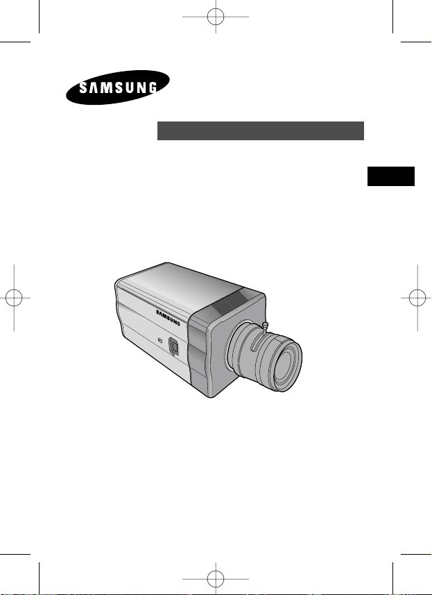
DIGITAL COLOR CAMERA
E
D
F
Sp
I
Pl
R
SCC-B1391(P)
SCC-B1091P
(AB68-00512B)SCC-B1391-01Eng 2005.6.17 4:7 PM ˘`1
Page 2
E
Important Safety Instructions
CAUTION: TO REDUCE THE
RISK OF ELECTRIC SHOCK,
DO NOT REMOVE REAR
COVER. NO USER
SERVICEABLE PARTS INSIDE.
REFER TO QUALIFIED
SERVICE PERSONNEL.
To prevent damage which may result in fire or electric shock hazard,
do not expose this appliance to rain or moisture.
This device complies with part 15 of the FCC Rules. Operation is
subject to the following two conditions.
1) This device may not cause harmful interference, and
2) This device must accept any interference that may cause undesired
operation.
CAUTION:
Danger of explosion if battery is incorrectly replaced.
Replace only with the same or equivalent type recommended by the
manufacturer.
Dispose of used batteries according to the manufacturer’s instructions.
This symbol indicates
high voltage is present
inside. It is dangerous to
make any kind of contact
with any inside part of this
product.
This symbol alerts you
that important literature
concerning operation and
maintenance has been
included with this product.
CAUTION
RISK OF ELECTRIC
SHOCK DO NOT OPEN
2
(AB68-00512B)SCC-B1391-01Eng 2005.6.17 4:7 PM ˘ `2
Page 3
3
E
1. Read these instructions.
2. Keep these instructions.
3. Heed all warnings.
4. Follow all instructions.
5. Do not use this apparatus near water.
6. Clean only with dry cloth.
7. Do not block any ventilation openings. Install in accordance
with the manufacturer’s instructions.
8. Do not install near any heat sources such as radiators, heat
registers, or other apparatus (including amplifiers) that produce
heat.
9. Do not defeat the safety purpose of the polarized or groundingtype plug. A polarized plug has two blades with one wider than
the other. A grounding type plug has two blades and a third
grounding prong. The wide blade or the third prong are provided
for your safety. If the provided plug does not fit into your outlet,
consult an electrician for replacement of the obsolete outlet.
10. Protect the power cord from being from being walked on or
pinched particularly at plugs, convenience receptacles, and the
point where they exit from the apparatus.
11. Only use attachments/accessories specified by the manufacturer.
12. Use only with cart, stand, tripod, bracket, or table specified by
the manufacturer, or sold with the apparatus. When a used,
caution when moving the cart/apparatus combination to avoid
injury from tip-over.
13. Unplug this apparatus. When a cart is used, use caution when
moving the cart/apparatus combination to avoid injury from tipover.
14. Refer all servicing to qualified service personnel. Servicing is
required when the apparatus has been damaged in any way,
such as power-supply cord or plug is damaged, liquid has been
spilled or objects have fallen into the apparatus, the apparatus
has been exposed to rain or moisture, does not operate
normally, or been dropped.
(AB68-00512B)SCC-B1391-01Eng 2005.6.17 4:7 PM ˘ `3
Page 4

4
E
Chapter 1 Introduction ........................................................ 5
Chapter 2 Special Features ............................................. 6
Chapter 3 Installation ......................................................... 7
Checking the contents of the package .............. 7
Precautions in Installation and Use ................... 8
Connecting Auto Iris Lens Connector ................ 9
Lens Fixing
........................................................... 10
Setting Lens Selection Switch
.................... 11
Back Focus Adjustment
................................ 11
Connecting Cables and Checking Operation ..... 13
Chapter 4 Part Names and Functions ............................... 15
Product Specification ........................................ 20
Contents
(AB68-00512B)SCC-B1391-01Eng 2005.6.17 4:7 PM ˘ `4
Page 5
5
E
This camera is the high-resolution monitoring camera of 540 TV Lines and can
provide the best monitoring function by connecting with the CCTV System.
❉
In the mechanical fluorescent light environment, if you attach MANUAL IRIS
LENS and turn the ELC switch among FUNCTION switches on, color may be
rolled.
In this case, supply AC power before you turn L/L switch among FUNCTION
switches on. (NTSC:60HZ , PAL:50HZ)
Chapter 1 Introduction
COLOR ROLLING is the problem that color on the
monitor screen changes non-periodically.
This happens when White Balance is not fixed,
because a mechanical fluorescent light flickers
when it’s cycle is the same to the cycle of the power
frequency.
(AB68-00512B)SCC-B1391-01Eng 2005.6.17 4:7 PM ˘ `5
Page 6
6
E
High Sensitivity
It has an up-to-date 1/3" Super-HAD IT CCD for an image of high sensitivity.
Resolution
It realizes high resolution resulting from full digital image processing
supported by a state-of-art digital signal technology.
Superior Back Light Adjustment Function
In case the object has a bright illumination or sunlight behind it, this camera
adjusts the image shaded by the back light for clear photographs.
Digital Power Supply Synchronization Method
The Full Digital Method Line Lock is realized in this camera, which adjusts
the vertical camera synchronization directly to improve controllability and
reliability of the camera.
Chapter 2 Special Features
(AB68-00512B)SCC-B1391-01Eng 2005.6.17 4:7 PM ˘ `6
Page 7
7
E
This chapter describes what should be checked before installation, how to
set the installation environment, and what should be done during installation.
Then, it describes how to install the camera and connect the cable in actual
circumstances.
Chapter 3 Installation
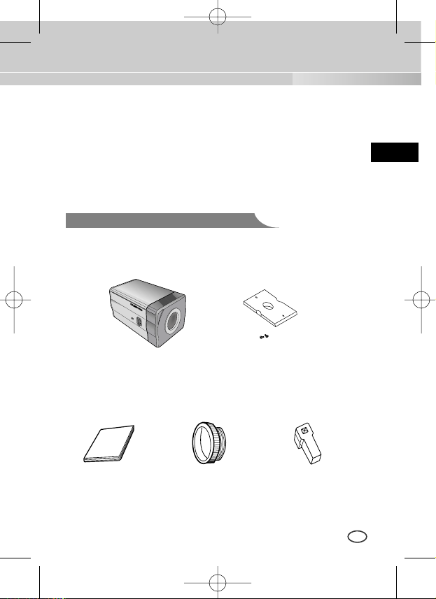
Be sure to check if the following items are included in the package.
Checking the contents of the package
Camera
Holder(Mount)
C Mount Adapter
Auto Iris
Lens Connector
User's Manual
Camera
(AB68-00512B)SCC-B1391-01Eng 2005.6.17 4:7 PM ˘ `7
Page 8
8
E
① Do not attempt to disassemble the camera yourself.
➁ Be cautious in handling the camera. Avoid striking or shaking the
camera. Be cautious to avoid damage on the camera caused by improper
storage or operation.
➂ Do not expose this camera to rain or moisture. Do not operate this
camera on a wet place.
➃ Do not use strong or abrasive detergents when cleaning the camera
body. Use a dry cloth to clean the camera.
⑤ Keep the camera at a cool place away from the direct sunlight. Leaving it
under the direct sunlight may result in the malfunction of the unit.
Precautions in Installation and Use
(AB68-00512B)SCC-B1391-01Eng 2005.6.17 4:7 PM ˘ `8
Page 9
9
E
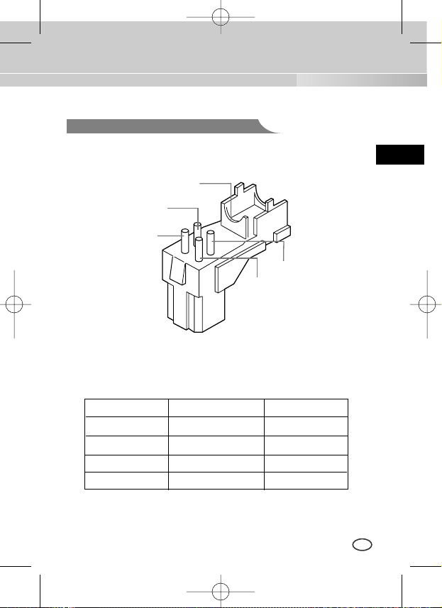
Connecting Auto Iris Lens Connector
Prepare the following Auto Iris Lens Connector supplied with the camera.
Connect the cable of the control cable, whose covering is stripped, to the
Auto Iris Lens Connector as shown below.
Rb
Pin3
Pin2
Pin4
Pin1
Pin No. DC Control Type VIDEO Control Type
1 Damp(-) Power (+12V)
2 Damp(+) N/A
3 Drive(+) VIDEO Signal
4 Drive(-) GROUND
(AB68-00512B)SCC-B1391-01Eng 2005.6.17 4:7 PM ˘ `9
Page 10
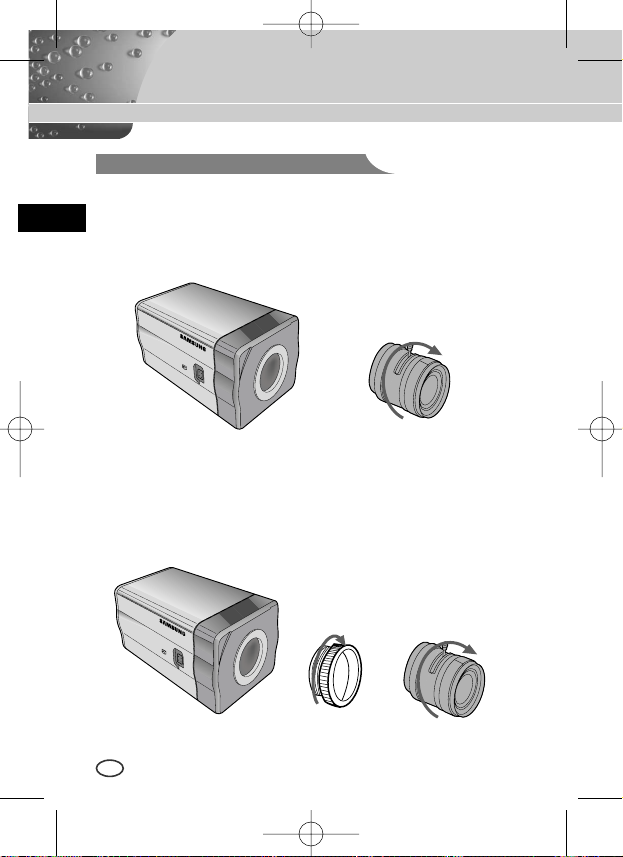
In case of CS lenses
Turn the CS lens clockwise until it is fixed as shown as follows.
In case of C lenses
Turn the C-mount adapter clockwise to fix it. Then turn the C lens
clockwise until it is fixed as follows.
Lens Fixing
CS lens
C lens
10
E
(AB68-00512B)SCC-B1391-01Eng 2005.6.17 4:7 PM ˘ `10
Page 11
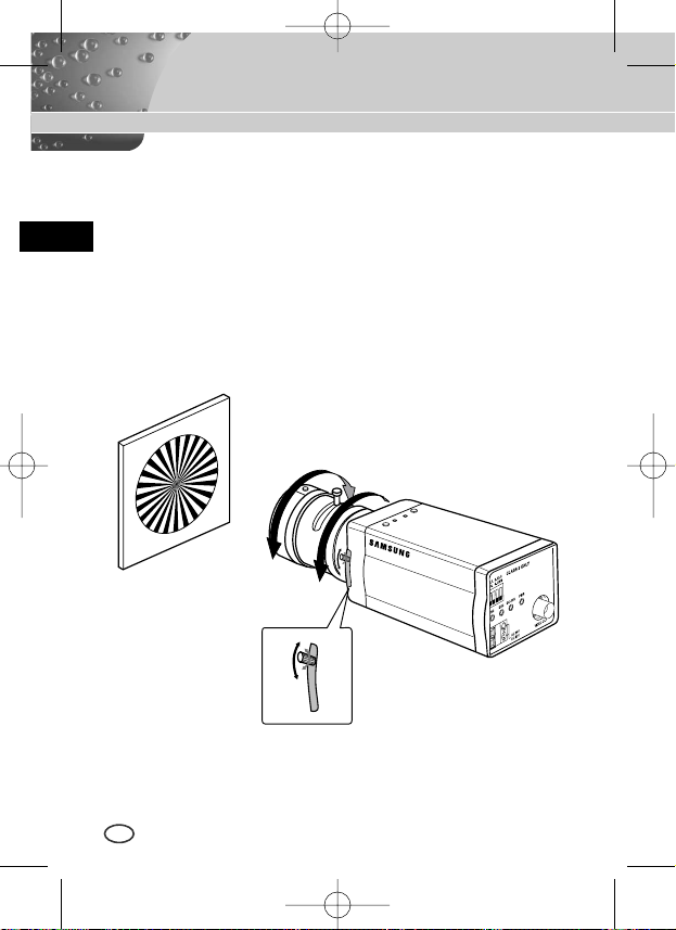
Back Focus Adjustment
Setting Lens Selection Switch
11
E
The camera back focus is adjusted at the plant before delivery, but some
lenses are out of focus though the number differs in types. If it's the case,
you should make the back focus adjustment as follows. First, this is the back
focus adjustment procedure for fixed focus lenses.
Lenses without zoom function
① Image an object with high resolution(letticed) at more than 10m distance
and put the lens focus ring in the infinite(
∞
) position.
➁ Rotate the BACK FOCUS control bar until the object is seen best.
➂ Tighten the BACK FOCUS control bar fixing screw.
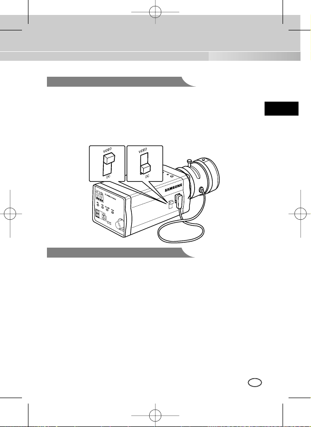
When lens mounting is completed, set the Lens selection Switch on the side
of the camera according to the mounted lens type. When the mounted lens
is an Auto Iris Lens of the DC control type, set the Lens Selection Switch to
"DC". When the mounted lens is an Auto Iris Lens of the Video control type,
set the Lens Selection Switch to "VIDEO".
(AB68-00512B)SCC-B1391-01Eng 2005.6.17 4:7 PM ˘ `11
Page 12
12
E
Lenses with zoom function
① Image an object with high resolution(letticed) at a distance of 3 to 5 m
and zoom in the lens as close to TELE as possible. Then adjust the lens
focus bar until the object is seen best.
➁ Zoom in the lens as close to WIDE as possible and adjust the BACK
FOCUS adjustment bar until the object is seen best.
➂ Repeat from ① to ➁ above 2 or 3 times until the focus on the ZOOM
TELE side is in line with that on the ZOOM WIDE side.
BACK FOCUS
CONTROL BAR
(AB68-00512B)SCC-B1391-01Eng 2005.6.17 4:7 PM ˘ `12
Page 13
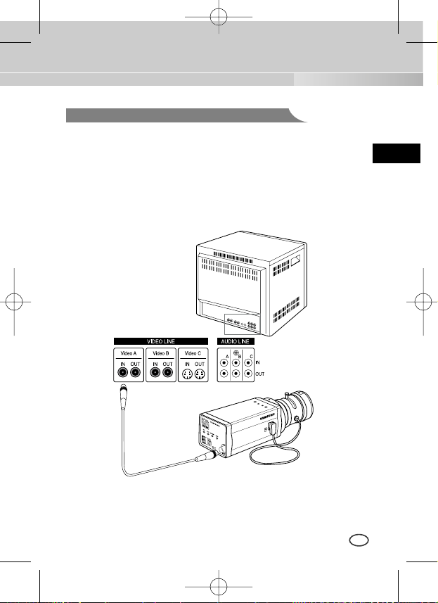
Connecting Cables and Checking Operation
13
E
1 First, connect the connector of the BNC cable to the Video Out terminal
2 Second, connect the other connector of the BNC cable to the Video In
terminal.
BNC cable
Video Out Terminal
Video In Terminal of
Monitor Rear Surface
(AB68-00512B)SCC-B1391-01Eng 2005.6.17 4:7 PM ˘ `13
Page 14
14
E
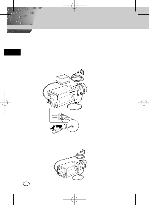
3 Third, connect the power cable.
① AC24V/DC12V Power Input Camera.
Connect 2 lines of the power adapter using a screwdriver to the power
IN Terminal of the camera as shown below.
❉
Without the distinction of the polarity, connect to the AC24 or DC12V
power source.
➁ AC230V Power Input Camera
Connect the power input cord to the AC230V power source.
(AB68-00512B)SCC-B1391-01Eng 2005.6.17 4:7 PM ˘ `14
Page 15
15
E
Chapter 4 Part Names and Functions
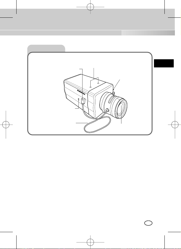
Side View
①
Mount Adapter Fixing Groove
This groove is used for screwing the mount adapter, a part of the bracket where the
camera will be installed.
➁
Camera Lens(Option)
This lens is installed in the camera.
❉
A camera lens with a stained surface should be cleaned softly with a lens
tissue or ethanol painted cotton cloth.
➂
Auto Iris Lens Connector
This connector provides the automatic shutter lens with power supply, control signal,
video signal, or DC signal necessary for the control of the lens shutter.
➃
Auto Iris Lens Control Cable
This cable transmits signal which controls the Iris.
⑤
ALC Lens Selection Switch
This Switch is used for select the type of Lens.
➅
Back Focus Control Bar
This bar is used for set back focus of the camera.
➃
Auto Iris Lens
Control Cable
⑤
ALC Lens
Selection Switch
➂
Auto Iris Lens
Connector
①
Mount Adapter Fixing
Groove
➅
Back Focus
Control Bar
➁
Camera Lens
(AB68-00512B)SCC-B1391-01Eng 2005.6.17 4:7 PM ˘ `15
Page 16
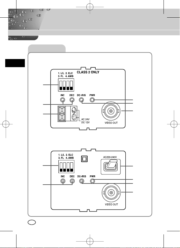
Rear View
16
E
AC24V/DC12V Camera (SCC-B1391(P))
AC230V Camera (SCC-1091P)
⑤
➁
➅
⑦
①
➂ ➃
⑤
①
➂ ➃
⑦
➁
➅
(AB68-00512B)SCC-B1391-01Eng 2005.6.17 4:7 PM ˘ `16
Page 17
17
E
① Power connection port
AC24V/DC12V Camera : It is a port connected to the power adaptor cable.
AC230V Camera : It is Power cord.
➁ POWER LED
If the power of a camera is supplied normally, the LED is ON.
➂➃INC and DEC Switch
Both switches increase or decrease the profit of RED and BLUE to fix a color
temperature as you wish while AWB among the FUNCTION switches is
off(USER) and control the vertical synchronous phase while both AWB and
L/L are on.
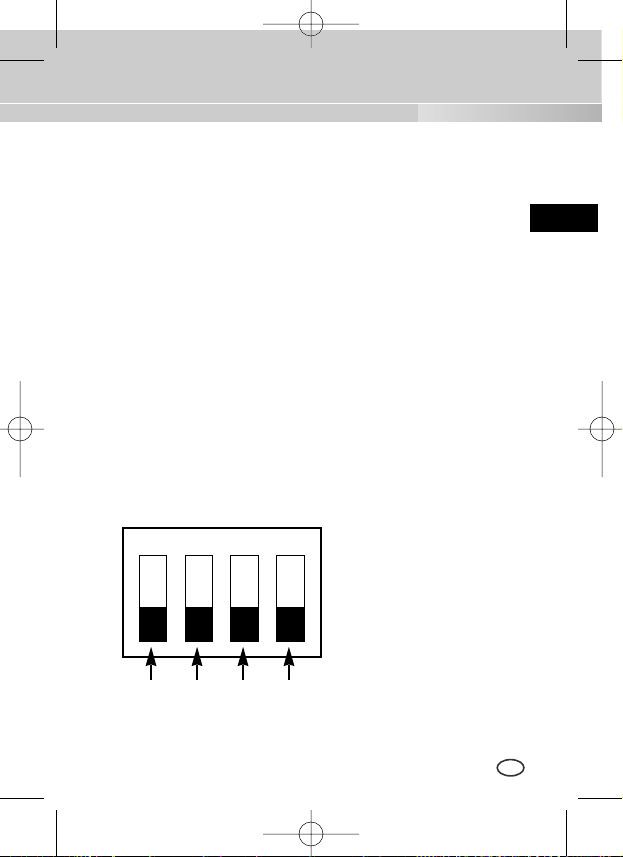
⑤ FUNCTION Switch
1. L/L 2. ELC
3. FL 4. AWB
SW1 SW2 SW3 SW4
ON
(AB68-00512B)SCC-B1391-01Eng 2005.6.17 4:7 PM ˘ `17
Page 18

18
E
1) SW1(L/L) :
Set to OFF, the camera activates the internal synchronization mode and set to ON, the power
synchronization mode. If you connect multi cameras to the sequential switcher to enter the
automatic conversion mode, the screen will bounce every screen while the camera stays in
INT(internal synchronization). Such bouncing phenomena may be cleared and screen conversion
becomes smooth by setting the L/L switch to ON and using the INT/DEC switch to control the
vertical synchronous phase.
❉
If you want to control the vertical synchronous phase with the INT/DEC switch when L/L is set
to ON, you shall set SW4 to AWB ON.
❉
In case of DC12V, INT(internal synchronizer) will be fixed without regard to ON/OFF of L/L.
2) SW2(ELC) :
Use this switch with the Manual Iris Lens. While this switch is ON, the speed of the electronic
shutter varies with the brightness of the subject from 1/60(50) to 1/100,000 sec for automatically
controlling the brightness of the screen. However, with the Auto Iris Lens (DC or Video Control),
be sure to switch OFF.
Color Rolling may occur in this mode. In that case, input AC power source to the camera and
select SW1 "ON".
(NTSC : 60HZ, PAL : 50HZ)
3) SW3(FL):
This is to prevent flicker on the screen when NTSC system is used in 50HZ power supply region
and PAL system is used in 60HZ power supply region. That is to prevent shaking on the
screen resulted from the discordance of the vertical sync frequency and the flicker frequency of
the illumination. While this switch is ON, the electronic shutter is fixed to 1/100sec (NTSC) or
1/120 sec (PAL).
4) SW4(AWB):
When setting up ON, the color of screen is adjusted automatically in accordance with the change
of lighting color temperature by the change of outer environment. (ATW) If the lighting condition is
steady, OFF setting is available. The camera memorizes the lighting color temperature at the
time when the switch setting is changed from ON to OFF, and the camera color is adjusted to the
memorized color temperature. (AWC) If the lighting color temperature is changed and you want
to make the camera be memorized/operated with the changed color temperature, re-operate the
switch On/Off operation. However, be aware that an error may occur under the following
conditions.
First, a case that the subject is big, single color of the high chroma, and in the center of
the screen or a case with almost no white color on the screen.
Second, a case with a specific illumination such as a natrium lamp
(AB68-00512B)SCC-B1391-01Eng 2005.6.17 4:7 PM ˘ `18
Page 19

19
E
➅
DC IRIS Level Controller
When the ALC lens selection switch is set to DC, use the same control bar as the
driver to control the IRIS level.
⑦
Video Output Port
This port shall be connected to the monitor video input port or equivalent. You
may output camera video signals through this port.
(AB68-00512B)SCC-B1391-01Eng 2005.6.17 4:7 PM ˘ `19
Page 20
20
E
Product Specification
SCC-B1391P/B1091P
ITEM
Contents
Product Type CCTV Camera
Broadcasting System PAL STANDARD SYSTEM
CCD 1/3 Super-HAD CCD
Effective Pixels 752(H) x 582(V)
Scanning Type 625 Line, 2:1 Interlace
INTERNAL : 15,625Hz(H)
50 Hz(V)
LINE LOCK : 15,625Hz(H)
50 Hz(V)
INTERNAL
LINE LOCK(When AC Power source is used)
Resolution(H) 540 TV Lines
S/N Ratio About 50dB
Frequency
Sync Type
Minimum Illumination
of Object
0.3 Lux
(AB68-00512B)SCC-B1391-01Eng 2005.6.17 4:7 PM ˘ `20
Page 21
ITEM
Contents
ALC
DC IRIS LENS
ALC/ELC VIDEO LENS
ELC
Electronic Shutter Iris Function (Max. 1/100 Ksec)
Color Temperature
AWB/MANUAL
BLC
ON
AGC ON
COMPOSITE VIDEO OUT
1V p_p 75Ω/BNC
Operating Temp
-10°C~+50
°C
Operating Humidity
~90%
Size 68(W)x55(H)x128.5(D)mm(included BNC)
B1391P : About 450g
B1091P : About 550g
21
E
Power Source
Power Consumption
Weight
B1391P : AC24V±10%(50Hz±0.3Hz), DC12V+10%~-5%
B1091P : AC220V~AC240V(50Hz±0.3Hz)
B1391P : About 3W
B1091P : About 4W
Video Output
(AB68-00512B)SCC-B1391-01Eng 2005.6.17 4:7 PM ˘ `21
Page 22

22
E
SCC-B1391
ITEM
Contents
Product Type CCTV Camera
Broadcasting System NTSC STANDARD SYSTEM
CCD 1/3 Super-HAD CCD
Effective Pixels 768(H) x 494(V)
Scanning Type 525 Line, 2:1 Interlace
INTERNAL : 15,750Hz(H)
59.94 Hz(V)
LINE LOCK : 15,750Hz(H)
60 Hz(V)
INTERNAL
LINE LOCK(When AC Power source is used)
Resolution(H) 540 TV Lines
S/N Ratio About 50dB
Frequency
Sync Type
Minimum Illumination
of Object
0.3 Lux
(AB68-00512B)SCC-B1391-01Eng 2005.6.17 4:7 PM ˘ `22
Page 23
ITEM
Contents
ALC
DC IRIS LENS
ALC/ELC VIDEO LENS
ELC
Electronic Shutter Iris Function (Max. 1/100 Ksec)
Color Temperature
AWB/MANUAL
BLC
ON
AGC ON
COMPOSITE VIDEO OUT
1V p_p 75Ω/BNC
Power Consumption About 3Watts
Operating Temp
-10°C~+50
°C
Operating Humidity
~90%
Size 68(W)x55(H)x128.5(D)mm(included BNC)
Weight
450g
23
E
Power Source
Video Output
AC24V ±10%(60Hz±0.3Hz), DC12V+10%~-5%
(AB68-00512B)SCC-B1391-01Eng 2005.6.17 4:7 PM ˘ `23
Page 24
Part No.:AB68-00512B
Correct Disposal of This Product
(Waste Electrical & Electronic Equipment)
(Applicable in the European Union and other European countries with separate collection systems)
This marking shown on the product or its literature, indicates that it should not be disposed with other
household wastes at the end of its working life. To prevent possible harm to the environment or human
health from uncontrolled waste disposal, please separate this from other types of wastes and recycle it
responsibly to promote the sustainable reuse of material resources.
Household users should contact either the retailer where they purchased this product, or their local
government office, for details of where and how they can take this item for environmentally safe recycling.
Business users should contact their supplier and check the terms and conditions of the purchase contract.
This product should not be mixed with other commercial wastes for disposal.
(AB68-00512B)SCC-B1391-01Eng 2005.6.17 4:7 PM ˘ `24
Page 25
BEDIENUNGSANLEITUNG
DIGITAL FARBE KAMERA
D
SCC-B1391(P)
SCC-B1091P
(AB68-00512B)SCC-B1391-Ger 2005.6.17 4:12 PM ˘`23
Page 26
D
Ziel dieser Informationen ist es, den ordnungsgemäßen Gebrauch dieses
Geräts sicherzustellen und dadurch Gefahren oder Sachbeschädigungen zu
vermeiden. Bitte befolgen Sie alle Anweisungen.
Sicherheitshinweise
Warnung
Warnung
Achtung
1. Achten Sie darauf, dass Sie nur den mitgelieferten Adapter verwenden. (Die
Verwendung eines anderen Adapters als des mitgelieferten kann Feuer, einen
Stromschlag oder die Beschädigung des Geräts verursachen.)
2. Beim Anschließen der Netz- und Signalkabel müssen zuvor die externen
Anschlussbuchsen überprüft werden. Schließen Sie die Alarmsignalkabeladern an
die Alarmanschlüsse, den Netzadapter an die Netzsteckdose und den
Gleichstromadapter an den Gleichstromeingang an, und achten Sie dabei auf die
richrige Polarität. (Ein falscher Anschluss an das Stromnetz kann Feuer, einen
Stromschlag oder die Beschädigung des Geräts verursachen.)
3.
Schließen Sie nicht mehrere Kameras an einen Adapter an. (Wird die Kapazität
überschritten, kann es zu einer anormalen Wärmeentwicklung oder Feuer kommen.)
4. Stecken Sie das Netzkabel fest in die Steckdose ein. (Ein loser Anschluss kann
Feuer verursachen.)
5. Bei der Wand- oder Deckeninstallation bringen Sie die Kamera sicher und fest an.
(Fällt die Kamera herunter, kann es zur Verletzung von Personen kommen.)
6. Plazieren Sie keine leitfähigen Gegenstände (wie z. B. Schraubenzieher, Münzen
und metallene Objekte) oder mit Wasser gefüllte Behälter auf der Kamera. (Das
kann zur Verletzung von Personen durch Feuer, Stromschlag oder herunterfallende
Gegenstände führen.)
Die Nichtbeachtung eines Warnhinweises kann
zum Tode oder zu schweren Verletzungen führen.
Die Nichtbeachtung eines mit Achtung gekennzeichneten
Hinweises kann zu Verletzungen und Sachschaden führen.
2
(AB68-00512B)SCC-B1391-Ger 2005.6.17 4:12 PM ˘ `24
Page 27
D
7. Die Kamera darf nicht an einem rußigen, staubigen oder feuchten Ort installiert
werden. (Andernfalls besteht die Gefahr eines Brandes oder Stromschlags.)
8. Beim Auftreten eines ungewöhnlichen Geruchs oder einer Rauchentwicklung, die
vom Gerät ausgehen, ziehen Sie unverzüglich das Netzkabel aus der Steckdose
und wenden Sie sich an Ihr Kundendienstzentrum. (Die Fortsetzung des
Gebrauchs kann in diesem Fall zu Feuer oder einem elektrischen Schlag führen.)
9. Sollte das Gerät nicht störungfrei funktionieren, setzen Sie sich mit Ihrem Händler
oder dem nächsten Kundendienstzentrum in Verbindung. Das Gerät darf niemals in
keiner Weise zerlegt oder modifiziert werden. (Samsung übernimmt keine Haftung
für Probleme, die durch unbefugte Abänderungen oder einen Reparaturversuch
herbeigeführt sind.)
10.
Beim Reinigen darf Wasser niemals direkt auf die Geräteteile gelangen. (Andernfalls
besteht die Gefahr eines Brandes oder Stromschlags.) Die Oberfläche kann mit einem
trockenen Tuch abgewischt werden. Verwenden Sie für das Gerät keine
Reinigungsmittel oder chemischen Reiniger, da sich durch solche Mittel die Farbe
ablösen und der Oberflächenüberzug beschädigt werden kann.
Achtung
1. Lassen Sie keine Gegenstände auf das Gerät fallen, und setzen Sie es keinen
starken Stößen aus. Setzen Sie die Kamera keinen starken Vibrationen oder
magnetischen Störfeldern aus.
2. Die Kamera darf nicht an Orten mit hohen Temperaturen (über 50 °C) bzw. tiefen
Temperaturen (unter -10 °C) oder hoher Luftfeuchtigkeit installiert werden.
(Andernfalls besteht die Gefahr eines Brandes oder Stromschlags.)
3. Installieren Sie das Gerät nicht in der Nähe von Wärmequellen, wie z. B. einem
Heizgerät oder Heizkörper, und an Orten, an denen es direktem Sonnenlicht
ausgesetzt ist. (Hier besteht Feuergefahr.)
4.
Wenn Sie die bereits installierte Kamera an einen anderen Ort verlegen wollen, achten
Sie darauf, die Kamera auszuschalten, bevor Sie sie abnehmen oder neu installieren.
5. Die Installation sollte an einer gut belüfteten Stelle erfolgen.
6. Ziehen Sie bei einem Gewitter den Netzstecker. (Die Nichtbeachtung kann zu
Feuer oder einer Beschädigung des Geräts führen.)
3
(AB68-00512B)SCC-B1391-Ger 2005.6.17 4:12 PM ˘ `25
Page 28
4
D
Kapitel 1 ÜBERSICHT ......................................................... 5
Kapitel 2 SPEZIALE MERKMALE ...................................... 6
Kapitel 3 Installation .............................................................. 7
Überprüfung des Inhalts in der Verpackung ........ 7
Sicherheitsmaßnahme bei Installation und ..........
Verwendung ...........................................................8
Anschließen des Auto Blende Objektiv ................
Konnektor .............................................................. 9
Einstellung des Objektivs ................................. 10
Einstellung Objektiv Auswahl Schalter ............11
Einstellung des Rück-brennpunktes
(Back Focus) ...................................................... 11
Anschluß der Kabel und Überprüfung
des Betriebs .........................................................13
Kapitel 4 BEZEICHNUNG DER TEILE UND IHRE
FUNKTIONEN .................................................... 15
Produkt Spezifikationen ...................................... 20
INHALTVERZEICHNIS
(AB68-00512B)SCC-B1391-Ger 2005.6.17 4:12 PM ˘ `26
Page 29
Diese Kamera ist die hochauflösende Überwachungskamera der 540 TV Linie,
indem sie die neueste Imaging Device (CCD) adoptiert und kann die beste
Überwachungsfunktion durch das Anschließen an das CCTV System zur
Verfügung stellen.
❉
In der mechanischen Leuchtstofflicht Umgebung, wenn Sie Manuelles
BLENDE Objektiv anbringen und den ELC Schalter unter FUNKTION Schaltern
einschalten, kann Farbe gerollt werden.
In diesem Fall, versorgen Sie AC Strom bevor Sie L/L Schalter unter FUNKTION
Schaltern einschalten.
(NTSC: 60HZ, PAL: 50HZ)
5
D
Kapitel 1
ÜBERSICHT
FARBE ROLLEN ist das Problem, dass sich die Farbe
auf den Monitor Schirm nicht periodisch verändert.
Dieses tritt auf, wenn Weißabgleich nicht fixiert ist, weil
ein mechanisches Leuchtstofflicht flimmert, wenn sein
Zyklus derselbe zum Zyklus der Strom Frequenz ist.
(AB68-00512B)SCC-B1391-Ger 2005.6.17 4:12 PM ˘ `27
Page 30

6
D
Hohe Empfindlichkeit
Es hat ein neuesten 1/3" Super-HAD IT CCD für ein Bild der hohen
Empfindlichkeit.
Resolution
Es verwirklicht eine hohe Resolution von vollen digitalen Bild-Entwickellung
mit der höchsten Digital Signal Technologie.
Superior Gegenlicht Einstellung Funktion
Im Fall von einer hellen Beleuchtung oder Sonnenstrahlen hinter dem
Gegenstand kann das Bild, das wegen der Gegenlicht verdunkelt worden
war, deutlich aufgenommen werden.
Digital Stromquelle Synchronisation Methode
Mit dem Vollen Digital Methode Linie Schluß (Line Lock) kann man die
vertikale Synchronisation der Kamera direkt struern, so die Kontrollfähigkeit
und die Zuverläßigkeit der Kamera zu verbessern.
Kapitel 2 Speziale Merkmale
(AB68-00512B)SCC-B1391-Ger 2005.6.17 4:12 PM ˘ `28
Page 31

7
D
In diesem Kapitel wird erläutert, was vor der Installation der Kamera zu
beachten ist, wie man eine geeignete Installationsstelle auswählt und
welche Vorsichtsmaßnahmen bei der Installation zu treffen sind. Nun
können Sie die Kamera installieren und die Kabel anschließen.
Kapitel 3 Installation
Überprüfen Sie bitte, ob die folgende Zubehörteile im Lieferumfang
enthalten sind.
Überprüfung des Inhalts in der Verpackung
Kamera Stütze
(Passepartout)
C Passepartout
Adapter
Auto Blende
Objektiv Anschluß
Manuale
d’utenteBedienun
gsanleitung
Kamera
(AB68-00512B)SCC-B1391-Ger 2005.6.17 4:12 PM ˘ `29
Page 32

8
D
① Versuchen Sie nicht, sich die Kamera auseinanderzubauen.
➁ Nehmen Sie sich von der Behandlung der Kamera in Acht. Vermeiden
Sie, die Kamera anzuschlagen oder zu rütteln. Seien Sie vorsichtig,
Beschädigung auf der Kamera zu vermeiden, die durch ungeeignete
Lagerung oder Betrieb verursacht wird.
➂ Lassen Sie diese Kamera nicht mit Regen oder Feuchtigkeit in Kontakt
bringen. Lassen Sie nicht diese Kamera auf einem nassen Platz laufen.
➃ Verwenden Sie keine starken oder abschleifenden Reinigungsmittel,
wenn Sie das Kameragehäuse säubern.
Benutzen Sie ein trockenes Tuch, um die Kamera zu säubern.
⑤ Halten Sie sich die Kamera an einem kühlen Platz, fern vom direkten
Tageslicht. Wenn die Kamera unter dem direkten Tageslicht ausgesetzt
wird, kann die Störung der Einheit ergeben.
Sicherheitsmaßnahme bei Installation und Verwendung
(AB68-00512B)SCC-B1391-Ger 2005.6.17 4:12 PM ˘ `30
Page 33

9
D
Anschließen des Auto Blende Objektiv Konnektor
Vorbereiten Sie den folgenden Auto Blende Objektiv Konnektor vor, der mit der
Kamera geliefert wird.
Schließen Sie das Kabel des Kontrollkabels, dessen Verkleidung abgestreift
wird, an den Auto Blende Objektiv Konnektor an, wie unten gezeigt.
Stecknadel Nr. DC Kontrolltyp VIDEO Kontrolltyp
1 Damp(-) Strom (+12V)
2 Damp(+) N/A
3 Drive(+) VIDEO Signal
4 Drive(-) GROUND
Rb
Pin3
Pin2
Pin4
Pin1
(AB68-00512B)SCC-B1391-Ger 2005.6.17 4:12 PM ˘ `31
Page 34

CS Objektive Fall
Der CS Objektiv im Uhrzeigersinn drehen, bis es wie unten befestigt wird.
C Objektive Fall
Der C Passepartout Adapter im Uhrzeigersinn drenen, um es zu
befestigen.
Dann drehen der C Objektiv im Uhrzeigersinn, bis es wie unten befestigt
wird.
Einstellung des Objektivs
CS Objektive
C Objektive
10
D
(AB68-00512B)SCC-B1391-Ger 2005.6.17 4:12 PM ˘ `32
Page 35

Einstellung Objektiv Auswahl Schalter
11
D
Einstellung des Rück-brennpunktes (Back Focus)
Die Kamera Rück-brennpunkt ist in der Fabrik vor der Lieferung eingestellt,
aber einige Objektive sind aus dem Brennpunkt, je nach der Objektivtypen.
Wenn es so ist, müßen Sie der Rück-brennpunkt wie folgt einstellen.
Zuerst, es ist das Rück-brennpunkt Einstell-verfahren für die Fixierten
Brennpunkt Objektive.
Objektive ohne Zoom Funktion
① Ein Gegenstand mit hocher Resolution (Gitterförmige Gegenstand) über
als 10m Entfernung einbilden und der Objektiv Brennpunktring in der
Unendlichkeit (
∞
) Position legen.
➁ Der RÜCK-BRENNPUNKT Einstellring drehen, bis der Gegenstand
deutlicher sein wird.
➂ Die Fixierschraube des RÜCK-BRENNPUNKT Einstellrings einschrauben.
Wenn Objektivmontage fertig ist, stellen Sie den Objektiv Auswahl Schalter auf
der Seite der Kamera entsprechend der angebrachten Objektiv Typ ein.
Wenn das angebrachte Objektiv ein Auto Blende Objektiv der DC Kontrolltyp ist,
stellen Sie den Objektiv Auswahl Schalter auf ‚ ‘DC’ ein,
Wenn das angebrachte Objektiv ein Auto Blende Objektiv der Video Kontrolltyp
ist, stellen Sie den Objektiv Auswahl Schalter auf ‚ ‘VIDEO’ ein.
(AB68-00512B)SCC-B1391-Ger 2005.6.17 4:12 PM ˘ `33
Page 36

12
D
Objektive mit Zoom Funktion
① Ein Gegenstand mit hocher Resolution (Gitterförmige Gegenstand)
einer Entfernung 3m bis 5m einbilden und der Zoom in dem Objektiv zu
TELE als möglich nahe einstellen. Dann drehen der Objektiv
Brennpunktring, bis der Gegenstand deutlicher sein wird.
➁ Der Zoom in dem Objektiv zu WIDE als möglich nahe einstellen und
dann drehen der RÜCK-BRENNPUNKT Einstellstab, bis der Gegenstand
deutlicher sein wird.
➂ Nummer ① bis ➁ und für 2 oder 3 male wiederholen, bis der Brennpunkt
auf der ZOOM TELE Seite mit denem auf der ZOOM WIDE Seite deutlich
passen wird.
BACK FOKUS
STEUERLEISTE
(AB68-00512B)SCC-B1391-Ger 2005.6.17 4:12 PM ˘ `34
Page 37

Anschluß der Kabel und Überprüfung des Betriebs
13
D
1 Schließen Sie zuerst das eine Ende des BNC-Videokabels an den
Videoausgang (VIDEO OUT) an.
2 Schließen Sie als nächstens das andere Ende des BNC-Kabels an die
Videoeingangsbuchse des Monitors an.
BNC KABEL
VIDEO AUS
TERMINAL
VIDEO EIN TERMINAL des
Monitor-hinterteils
(AB68-00512B)SCC-B1391-Ger 2005.6.17 4:12 PM ˘ `35
Page 38

14
D
3 Dritte schließt an das Stromkabel an.
① AC24V/DC12V Stromeingang Kamera
Schließt 2 Linien des Stromadapters mit der Verwendung des
Kreuzschraubenziehers an Strom EIN Terminal der Kamera an, wie
unten angezeigt.
❉
Ohne die Unterscheidung der Polarität, schließt an AC24V oder
DC12V Stromquelle an.
➁ AC230V Stromeingang Kamera
Schließt das Stromeingangskabel an AC230V Stromquelle an.
(AB68-00512B)SCC-B1391-Ger 2005.6.17 4:12 PM ˘ `36
Page 39

15
D
Kapitel 4 Teilnamen und Funktionen
Rückseite Ansich
①
Passepartout Adapter Befestigungsrille
Diese Rille benutzt für die Befestigung des Adapters, ein Teil
der Klammer wo die Kamera installiert wird.
➁
Automatische Verschluß Objektive (Option)
Dieses Objektiv ist in der Kamera installiert werden.
❉
Eine Objektiv der Oberfläche der Kamera muß mit einem Objektivpapier oder in
Äthan benetzten Baumwolltuch sanft reinigen werden.
➂
Automatischer Verschluß Objektiv Anschluß
Dieser Anschluß versorgt das automatische Verschluß Objektiv mit dem Stromversorgung, Kontrollsignal, Videosignal oder DC Signal, nötwendig für die Kontrolle
des Objektiv-verschlußes.
➃
Auto Blende Objektiv Steuerkabel
Dieses Kabel überträgt Signal, das die Blende steuert.
⑤
ALC Objektiv Auswahl Schalter
Dieser Schalter wird für Auswahl des Objektivtypen verwendet.
➅
Gegen Brennpunkt (Back Focus) Kontrollstab
Diese Leiste wird für Back Fokus Einstellung der Kamera verwendet.
➃
Auto Blende Objektiv
Steuerkabel
⑤
ALC Objektiv
Auswahl Schalter
➂
Automatischer Verschluß
Objektiv Anschluß
①
Passepartout Adapter
Befestigungsrille
➅
Gegen Brennpunkt (Back
Focus) Kontrollstab
➁
Automatische
Verschluß Objektive
(AB68-00512B)SCC-B1391-Ger 2005.6.17 4:12 PM ˘ `37
Page 40

Vista Posteriore
16
D
AC24V/DC12V Kamera (SCC-B1391(P))
AC230V Kamera (SCC-1091P)
⑤
➁
➅
⑦
①
➂ ➃
⑤
①
➂ ➃
⑦
➁
➅
(AB68-00512B)SCC-B1391-Ger 2005.6.17 4:12 PM ˘ `38
Page 41

17
D
① Strom Anschlussport
AC24V/DC12V Kamera : Es ist ein Port, das an das Strom Adapter Kabel
angeschlossen wird.
AC230V Kamera : Es ist Netzanschlusskabel.
➁ Strom LED
Wenn der Strom einer Kamera normalerweise geliefert wird, schaltet LED ein.
➂➃INC und DEC Schalter
Beide Schalter erhöhen oder verringern den Profit von ROT und BLAU, um
eine Farbe Temperatur zu regeln, wie Sie wünschen, während AWB unter
den FUNKTION Schaltern aus(BENUTZER) ist, und steuern die vertikale
synchrone Phase, während AWB und L/L eingeschaltet sind.
⑤ FUNKTION Schalter
1. L/L 2. ELC
3. FL 4. AWB
SW1 SW2 SW3 SW4
EIN
(AB68-00512B)SCC-B1391-Ger 2005.6.17 4:12 PM ˘ `39
Page 42

18
D
1) SW1(L/L):
Wenn es auf AUS eingestellt ist, aktiviert die Kamera den internen Synchronisierungsmodus
und wenn es auf EIN eingestellt ist, der Power Synchronisierungsmodus. Wenn Sie Multi
Kameras an den sequentiellen Schalter anschließen, um den automatischen
Konvertierungsmodus einzugeben, prallt der Schirm jeden Schirm auf, während die Kamera
in der INT(interne Synchronisierung) bleibt. Solche Aufprallen Phänomene können gelöscht
werden und Schirm Konvertierung wird reibungslos, indem Sie den L/L Schalter auf EIN
einstellen und den INT/DEC Schalter verwenden, um die vertikale synchrone Phase zu
steuern.
❉
Wenn Sie die vertikale synchrone Phase mit dem INT/DEC Schalter steuern möchten,
wenn L/L auf EIN eingestellt ist, stellen Sie SW4 auf AWB EIN ein.
❉
Falls von DC12V, wird INT(intern Synchronizer) ohne Rücksicht auf EIN/AUS von L/L
festgelegt
2) SW2(ELC):
Verwenden Sie diesen Schalter mit dem manuellen Blende Objektiv. Während dieser Schalter
auf EIN einstellt ist, schwankt die Geschwindigkeit des elektronischen Shutters mit der
Helligkeit des Gegenstandes von 1/60(50) bis 1/100,000 Sek. für automatische Steuerung der
Helligkeit des Schirmes. Jedoch seien Sie sicher, mit dem Auto Blende Objektiv (DC oder
Video Kontrolle) auf AUS einzustellen. Farbe Rollen kann in diesem Modus auftreten.
In diesem Fall, geben Sie AC Stromquelle zur Kamera ein und wählen Sie SW1 auf "EIN"
aus. (NTSC: 60HZ, PAL: 50HZ)
3) SW3 (FL):
Dieses ist zur Verhinderung des Flimmers auf dem Schirm, wenn NTSC System in der
50HZ Stromversorgung Bereich benutzt wird und PAL System in der 60HZ Stromversorgung
Bereich benutzt wird. Das ist zur Verhinderung der auf dem Schirm resultierten Erschütterung
von der Uneinigkeit des vertikalen Synchr. Frequenz und der Flimmer Frequenz der
Ablichtung. Während dieser Schalter auf EIN eingestellt ist, wird der elektronische Shutter an
1/100 Sek. (NTSC) oder an 1/120 Sek. (PAL) fixiert.
4) SW4 (AWB):
Wenn es auf EIN eingestellt ist, wird die Farbe des Schirmes automatisch in
Übereinstimmung mit der Änderung der Beleuchtungsfarbe Temperatur durch die
Veränderung der außen Umgebung justiert. (ATW) Wenn der Beleuchtungszustand
unveränderlich ist, ist AUS Einstellung verfügbar. Die Kamera merkte sich die
Beleuchtungsfarbe Temperatur, zu der Zeit wenn die Schalter Einstellung von EIN nach AUS
geändert wird, und die Kamera Farbe wird auf die gemerkte Farbe Temperatur
justiert. (AWC) Wenn die Beleuchtungsfarbe Temperatur sich verändert wird und Sie die
Kamera mit der geänderten Farbe Temperatur gemerkt/betriebt werden lassen möchten,
betreiben Sie den Schalter EIN/AUS Betrieb wieder. Jedoch beachten Sie, dass eine Störung
unter den folgenden Bedingungen auftreten kann.
Zuerst ein Fall, dass der Gegenstand groß, einzelne Farbe mit dem hohen
Sättigungsgrad und in der Mitte des Schirmes oder ein Fall mit fast keiner weißen Farbe
auf dem Schirm ist.
Zweitens, ein Fall mit einer spezifischen Ablichtung wie einer Natrium Lampe.
(AB68-00512B)SCC-B1391-Ger 2005.6.17 4:12 PM ˘ `40
Page 43

19
D
➅
DC Blende Niveau Kontrolleur
Wenn der ALC Objektiv Auswahl Schalter auf DC eingestellt wird, benutzen Sie den
gleichen Kontrollleiste wie der Treiber, um das BLENDE Niveau zu steuern.
⑦
Video Ausgangsport
Dieser Port wird an das Monitor Video Eingangsport oder an das Entsprechendes
angeschlossen. Sie können Ausgang Kamera Videosignale durch diesen Port
ausgeben.
(AB68-00512B)SCC-B1391-Ger 2005.6.17 4:12 PM ˘ `41
Page 44

20
D
Produkt Spezifikationen
SCC-B1391P/B1091P
ARTIKEL
BESCHREIBUNG
Produkt Typ CCTV Kamera
Rundfunksystem PAL STANDARD SYSTEM
CCD 1/3” Super-HAD CCD
Effektive Pixel 752 (H) x 582 (V)
Scanning Typ 625 Linien, 2:1 Zeilensprung
INTERN : 15,625Hz(H)
50 Hz(V)
LINIE Schleuse :
15,625Hz(H)
50 Hz(V)
INTERN
LINIE Schleuse(Wenn AC Stromquelle besetzt ist)
Auflösung 540 TV Linie
S/N Ratio Ca. 50dB
Frequenz
Sync Typ
Minimale Ablichtung
des Gegenstandes
0.3 Lux
(AB68-00512B)SCC-B1391-Ger 2005.6.17 4:12 PM ˘ `42
Page 45

ARTIKEL
BESCHREIBUNG
AGC EIN
Video Ausgang
Temperatur bei Betrieb
-10°C~+50
°C
GröBe 68(W)x55(H)x128.5(D)mm(inkl. BNC)
Gewicht
21
D
Stromquelle
Energieverbrauch
Luftfeuchtigkeit
bei Betrieb
B1391P : AC24V±10%(50Hz±0.3Hz), DC12V+10%~-5%
B1091P : AC220V~AC240V(50Hz±0.3Hz)
BLC(Gegenlichtko
mpensation)
Farbe Temperatur
ALC/ELC
EIN
Composite Videoausgang
1Vp-p 75 Ohms/BNC
B1391P : Ca. 3W
B1091P : Ca. 4W
~90%
B1391P: Ca. 450
g
B1091P: Ca. 550
g
AWB/MANELLE
ALC
DC BLENDE OBJEKTIV
VIDEO OBJEKTIV
ELC
Elektronische Shutter Blende Funktion (Max.1/100 Ksek)
(AB68-00512B)SCC-B1391-Ger 2005.6.17 4:12 PM ˘ `43
Page 46

ARTIKEL
BESCHREIBUNG
Produkt Typ CCTV Kamera
Rundfunksystem NTSC STANDARD SYSTEM
CCD 1/3” Super-HAD CCD
Effektive Pixel 768 (H) x 494 (V)
Scanning Typ 525 Linien, 2:1 Zeilensprung
INTERN : 15,750Hz(H)
59.94 Hz(V)
LINIE Schleuse :
15,750Hz(H)
60 Hz(V)
INTERN
LINIE Schleuse(Wenn AC Stromquelle besetzt ist)
Auflösung 540 TV Linie
S/N Ratio Ca. 50dB
22
D
SCC-B1391
Frequenz
Sync Typ
Minimale Ablichtung
des Gegenstandes
0.3 Lux
Produkt Spezifikationen
(AB68-00512B)SCC-B1391-Ger 2005.6.17 4:12 PM ˘ `44
Page 47

ARTIKEL
BESCHREIBUNG
ALC
DC BLENDE OBJEKTIV
ALC/ELC VIDEO OBJEKTIV
ELC
Elektronische Shutter Blende Funktion (Max.1/100 Ksek)
AGC EIN
Video Ausgang
Composite Videoausgang
1Vp-p 75 Ohms/BNC
Energieverbrauch Ca. 3W
Temperatur bei Betrieb
-10°C~+50
°C
GröBe 68(W)x55(H)x128.5(D)mm(inkl. BNC)
Gewicht
450g
23
D
Stromquelle
AC24V ±10%(60Hz±0.3Hz), DC12V+10%~-5%
BLC(Gegenlichtko
mpensation)
Luftfeuchtigkeit
bei Betrieb
Farbe Temperatur
EIN
~90%
AWB/MANELLE
(AB68-00512B)SCC-B1391-Ger 2005.6.17 4:12 PM ˘ `45
Page 48

Part No.:AB68-00512B
Korrekte Entsorgung dieses Produkts (Elektromüll)
(Anzuwenden in den Ländern der Europäischen Union und anderen euroäischen Ländern mit einem
separaten Sammelsystem)
Die Kennzeichnung auf dem Produkt bzw. auf der dazugehörigen Literatur gibt an, dass es nach seiner
Lebensdauer nicht zusammen mit dem normalen Haushaltsmüll entsorgt werden darf. Entsorgen Sie
dieses Gerät bitte getrennt von anderen Abfällen, um der Umwelt bzw. der menschlichen Gesundheit nicht
durch unkontrollierte Müllbeseitigung zu schaden. Recyceln Sie das Gerät, um die nachhaltige
Wiederverwertung von stofflichen Ressourcen zu fördern.
Private Nutzer sollten den Händler, bei dem das Produkt gekauft wurde, oder die zuständigen Behörden
kontaktieren, um in Erfahrung zu bringen, wie sie das Gerät auf umweltfreundliche Weise recyceln können.
Gewerbliche Nutzer sollten sich an Ihren Lieferanten wenden und die Bedingungen des Verkaufsvertrags
konsultieren. Dieses Produkt darf nicht zusammen mit anderem Gewerbemüll entsorgt werden.
(AB68-00512B)SCC-B1391-Ger 2005.6.17 4:12 PM ˘ `46
Page 49

F
Manuel d’Utilisation
CAMÉRA NUMÉRIQUE COULEUR
SCC-B1391(P)
SCC-B1091P
(AB68-00512B)SCC-B1391-Fra 2005.6.17 4:10 PM ˘`45
Page 50

2
F
L’objectif des précautions de sécurité est d’assurer l’utilisation correcte de ce
produit afin d’éloigner tout risque et tout dégât à la propriété. Assurez-vous de
bien observer toutes les précautions.
Précautions de sécurité
Avertissement
Avertissement
Mise en garde
1. Assurez-vous d’utiliser uniquement l’adaptateur fourni avec le produit.
(L’utilisation d’un adaptateur autre que celui fourni peut endommager le produit
ou causer un incendie ou des décharges électriques.)
2. Avant de brancher le cordon d’alimentation et les câbles de signal, vérifiez
d’abord les bornes extérieures. Reliez les câbles des signaux d’alarme à leur
borne respective. Branchez l’adaptateur CA sur la prise CA et l’adaptateur CC
sur la prise CC tout en tenant compte de la bonne polarité. (La connexion
incorrecte à la source d’alimentation peut endommager le produit ou causer un
incendie ou des décharges électriques.)
3. Ne branchez jamais plus d’une caméra sur un seul adaptateur. (Le dépassement
de la capacité de charge risque de générer une chaleur anormale au point de
causer un incendie.)
4. Branchez le cordon d’alimentation sur la prise murale. Assurez-vous que la
connexion est solidement fixée. (Une mauvaise connexion peut constituer le
risque d’un incendie.)
5. Lorsque vous installez la caméra au mur ou au plafond, assurez-vous qu’elle y
soit fixée solidement et de faáon sécuritaire. (La chute de la caméra peut causer
des blessures corporelles.)
6. Ne placez jamais d’objets conducteurs (p. ex., un tournevis, des pièces de
monnaie, tout autre objet métallique) ni de contenants remplis d’eau sur la
Ne pas tenir compte d’un avertissement risque
de causer des blessures graves, voire mortelles.
Ne pas tenir compte d’une mise en garde peut entraåner
des blessures cor porelles ou des dégâts à la propriété.
(AB68-00512B)SCC-B1391-Fra 2005.6.17 4:10 PM ˘ `46
Page 51

3
F
caméra. (Cela pourrait présenter un risque de blessures corporelles en raison
d’un incendie, d’une décharge électrique ou de la chute d’un objet.)
7.
N’installez pas la caméra dans un emplacement plein de suie, de poussière ou
d’humidité. Cela pourrait causer un incendie ou provoquer une décharge électrique.
8. Si vous détectez une odeur étrange ou de la fumée qui sort du produit,
débranchez immédiatement le cordon d’alimentation et contactez le centre de
soutien technique. (Une sollicitation continue de l’appareil dans ces conditions
pourrait causer un incendie ou provoquer des décharges électriques.)
9.
Si ce produit cesse de fonctionner correctement, communiquez avec votre revendeur
ou le centre d’entretien dans votre localité. Ne démontez ni ne modifiez jamais ce
produit. (Samsung n’est pas responsable des problèmes techniques découlant d’une
modification non autorisée ou d’une tentative de réparation.)
10. Lorsque vous nettoyez le produit, veillez à ne pas vaporiser d’eau directement
sur les composants du produit. (Cela pourrait causer un incendie ou provoquer
une décharge électrique.) Nettoyez la surface au moyen d’un chiffon doux.
N’utilisez jamais de détersifs ni de nettoyants chimiques. Cela pourrait
provoquer une décoloration ou endommager le fini du produit.
Mise en garde
1. Ne laissez pas tomber d’objets sur le produit ni ne soumettez le produit à de
forts coups. Ne placez pas le produit dans un emplacement où il pourrait
subir de fortes vibrations ou des interférences magnétiques.
2. Ne placez pas le produit dans un emplacement où il fait très chaud (plus de
50°C/122°F), très froid (moins de ‘10°C/14°F) ou très humide. (Cela pourrait
causer un incendie ou provoquer une décharge électrique.)
3. Évitez un emplacement où le produit est exposé à des rayons directs du soleil
ou à une source de chaleur, telle qu’un radiateur ou un appareil de chauffage.
(Le non-respect de cette consigne pourrait présenter un risque d’incendie.)
4. Si vous désirez déplacer le produit à la suite de son installation, assurez-vous
de couper le courant avant son déplacement et sa réinstallation.
5. Installez le produit dans une aire bien ventilée.
6. En cas d’orage, débranchez le cordon électrique de la prise murale. (Le nonrespect de cette consigne pourrait provoquer un incendie ou endommager le
produit.)
(AB68-00512B)SCC-B1391-Fra 2005.6.17 4:10 PM ˘ `47
Page 52

4
F
Chapitre 1 Introduction ............................................................5
Chapitre 2 Caractéristiques .....................................................6
Chapitre 3 Installation..............................................................7
Lors du déballage, vérifiez le contenu du paquet ..7
Précautions dans l’Installation et Utilisatio.............8
Brancher le connecteur automatique
d'objectif d'iris ........................................................9
Fixation de l’objectif..............................................10
Réglage du bouton de sélection de l’objectif........11
Focalisation .........................................................11
Connexion du câble & Vérification
du fonctionnement ...............................................13
Chapitre 4 Noms et Fonctions des Composants ...................15
Spécifications Techniques ...................................20
Sommaire
(AB68-00512B)SCC-B1391-Fra 2005.6.17 4:10 PM ˘ `48
Page 53

Cette caméra de surveillance à haute résolution de 540 lignes de TV en
adoptant le plus nouveau dispositif de formation image (CCD) et peut fournir
la meilleure fonction de surveillance en se reliant au système de CCTV.
❉ Dans l'environnement de lampe fluorescente, si vous activé I’IRIS
MANUEL et mettez le bouton ELC parmi des boutons de FONCTION en
marche, la couleur peut
roulée
. Dans ce cas-ci, appliquer le courant
alternatif avant de mettre le bouton de L/L parmi des boutons de
FONCTION en marche. (NTSC:60HZ , PAL:50HZ)
5
F
Chapitre 1 Introduction
Roulement de couleur est un problème sur l’écran de
mouvements irréguliés. Cela se produit quand la Balance
de blanc n’est pas fixé parce qu’une lampe fluorescente
clignote lorsque son cycle est identique à celui de la
fréquence d’alimentation.
(AB68-00512B)SCC-B1391-Fra 2005.6.17 4:10 PM ˘ `49
Page 54

6
F
Haute sensibilité
La technologie de pointe ‘1/3" Super-HAD IT CCD’ permet d’obtenir des
images d’une haute sensibilité.
Résolution
La caméra offre une haute résolution grâce à une technologie ultramoderne
de traitement numérique des images.
Excellente correction du contre-jour
Malgré la présence d’un éclairage puissant ou d’un rayonnement solaire
derrière l’objet, cette caméra permet d’obtenir une prise de vue nette grâce
à la correction des images assombries par le contre-jour.
Mode de synchronisation numérique
Le mode de synchronisation numérique des fréquences trame et réseau est
intégré dans cette caméra pour un réglage direct de la synchronisation
verticale de la caméra, permettant un contrôle plus pratique et fiable.
Chapitre 2 Caractéristiques
(AB68-00512B)SCC-B1391-Fra 2005.6.17 4:10 PM ˘ `50
Page 55

7
F
Ce chapitre contient des informations relatives aux vérifications avant
l’installation de la caméra, au choix de sa mise en place et aux précautions
d’installation. Veuillez lire attentivement ces indications avant d’installer la
caméra et de connecter le câble.
Adaptateur (‘Mount’)
Chapitre 3 Installation
Connecteur de l’objectif
à diaphragme
automatique
Manuel d’utilisation
Caméra
Vérifiez que les éléments suivants sont inclus dans l’emballage.
Lors du déballage, vérifiez le contenu du paquet
Adaptateur ‘C
Mount’
(AB68-00512B)SCC-B1391-Fra 2005.6.17 4:10 PM ˘ `51
Page 56

8
F
① N’essayez pas de démonter la caméra par vous même.
➁ Soyez prudent en manipulant la caméra. Évitez de la frapper ou secouer.
Soyez prudent pour éviter des dommages sur la caméra provoqué par
stockage ou opération inapproprié.
➂ N'exposez pas cette caméra à la pluie ou à l'humidité. Ne l'actionnez pas
dans un endroit humide.
➃ N'employez pas de détergents forts ou abrasifs pour la nettoyer.
Employez un tissu sec pour nettoyer la caméra.
⑤ Conservez la caméra dans un endroit frais à l’abri du rayon de soleil
direct. Autrement, cela peut provoquer un défaut de fonctionnement de
l'unité.
Précautions dans l’Installation et Utilisatio
(AB68-00512B)SCC-B1391-Fra 2005.6.17 4:10 PM ˘ `52
Page 57

9
F
Brancher le connecteur automatique
d'objectif d'iris
Préparer le connecteur automatique d'objectif d'iris fourni avec la caméra
comme montré ci-dessous.
Reliez le câble du câble de commande, dont la bâche est dépouillée, au
connecteur automatique d'objectif d'iris comme montré ci-dessous.
N° de la clé Type de contrôle DC Type de contrôle VIDEO
1 Damp (-) Alimentation (+12V)
2 Damp (+) Non utilisé
3 Drive (+) Signal VIDEO
4 Drive (-) GROUND
Rb
Pin3
Pin2
Pin4
Pin1
(AB68-00512B)SCC-B1391-Fra 2005.6.17 4:10 PM ˘ `53
Page 58

Fixation de l’objectif
10
F
Lors de l’objectif CS :
Vissez l’objectif CS dans le sens des aiguilles d’une montre, comme
l’indique la figure ci-dessous.
Lors de l’objectif C :
Vissez d’abord le support d’installation dans le sens des aiguilles d’une
montre. Vissez ensuite l’objectif C dans le même sens, comme l’indique
la figure ci-dessous.
l’objectif CS
l’objectif C
(AB68-00512B)SCC-B1391-Fra 2005.6.17 4:10 PM ˘ `54
Page 59

Réglage du bouton de sélection de l'objectif
11
F
Focalisation
La focale de la caméra est déjà réglée en sortie d’usine, mais cette
focalisation peut ne pas correspondre à certains types d’objectif. Dans ce
cas, réglez la focale selon les indications suivantes. Ceci est une méthode
pour le réglage d’un objectif à focale fixe.
Objectif sans fonction de zoom
①
Prenez l’image d’un objet net (en forme de carreau) placé à une
distance de plus de 10 m et positionnez l’anneau de la focale de
l’objectif sur l’infini (
∞
).
➁ Tournez-le jusqu’à ce que l’image de l’objet soit la plus nette possible.
➂ Fixez l’anneau de réglage de la focale en serrant la vis.
Lorsque le montage de l’objectif est accompli, installez le Bouton de
sélection d'objectif à côté de la caméra selon le type d'objectif monté.
Lorsque l'objectif monté est un objectif automatique d'iris du type de
commande de CC, installez le bouton de sélection d'objectif au "CC",
Quand l'objectif monté est un objectif automatique d'iris du type de
commande Vidéo, installez le bouton de sélection d'objectif à la "VIDÉO".
(AB68-00512B)SCC-B1391-Fra 2005.6.17 4:10 PM ˘ `55
Page 60

12
F
Objectif avec fonction de zoom
① Prenez l’image d’un objet net (en forme de carreau) placé à une
distance de 3 à 5 m, puis réglez le zoom au maximum vers TELE.
Ensuite, réglez l’anneau de la focale jusqu’à ce que l’image de l’objet soit
la plus nette possible.
➁ Réglez le zoom au maximum vers WIDE et tournez la barre de
focalisation jusqu’à ce que l’image de l’objet soit la plus nette possible.
➂ Répétez ① ou ➁ fois les procédés 2 et 3 jusqu’à de que la focale sur le
côté ZOOM TELE et celle sur le côté ZOOM WIDE soient correctement
réglées.
Barre de focalisation
(AB68-00512B)SCC-B1391-Fra 2005.6.17 4:10 PM ˘ `56
Page 61

Connexion du câble & Vérification du fonctionnement
13
F
1 Reliez d’abord un côté du connecteur du câble BNC à la sortie VIDEO
(VIDEO OUT).
2 Reliez l’autre côté du connecteur du câble BNC à l’entrée VIDEO du
moniteur.
Câble BNC
Sortie Vidéo
Entrée Vidéo située derrière
le moniteur
(AB68-00512B)SCC-B1391-Fra 2005.6.17 4:10 PM ˘ `57
Page 62

14
F
3 Relier le câble d’alimentation
① Puissance consommée de la caméra : CA24V/CC12V
Reliez 2 lignes de l'adapteur de puissance à l'aide d'un tournevis
Phillips à la puissance de la borne IN de la caméra comme montré cidessous.
❉
Sans distinction de la polarité, reliez au blog d’alimentation CA24V ou
CC12V.
➁ Puissance consommée de la caméra : CA230
Brancher le câble au bloc d’alimentation CA230V.
(AB68-00512B)SCC-B1391-Fra 2005.6.17 4:10 PM ˘ `58
Page 63

15
F
Chapitre 4 Noms et Fonctions des Composants
Seite Ansicht
①
La cannelure de fixage d'adaptateur de monture
Cette cannelure est employée pour visser l'adaptateur de monture, une pièce du
support où la caméra sera installée.
➁
Objectif du caméra ( Option )
Cet objectif est installé dans le caméra.
❉
Un objectif de caméra avec une surface souillée devrait être nettoyé doucement
avec un tissu d'objectif ou un tissu de coton imprégné d’éthanol.
➂
Le connecteur automatique d'objectif d'iris
Ce connecteur fournit à l'objectif automatique d'obturateur l'alimentation d'énergie, le
signal de commande, le signal visuel, ou le signal de C.C nécessaire pour la
commande de l'obturateur d'objectif.
➃
Câble de réglage de l’objectif à Iris automatique
Ce câble transmet le signal qui régle l’Iris.
⑤
Bouton de sélection de l’Objectif à ALC
Ce bouton est utilisé pour sélectionner le type d’objectif.
➅
Barre de focalisation
Cette barre est utilisée pour régler la focale minimale du zoom du caméra.
➃
Câble de réglage de
l’objectif à Iris automatique
⑤
Bouton de sélection
de l’objectif ALC
➂
Le connecteur
automatique d'objectif d'iris
➁
Objectif du caméra
➅
Barre de focalisation
①
La cannelure de fixage
d'adaptateur de monture
(AB68-00512B)SCC-B1391-Fra 2005.6.17 4:10 PM ˘ `59
Page 64

Vue arrière
16
F
CA24V/CC12V Caméra(SCC-B1391(P))
CA230V Caméra (SCC-B1091P)
⑤
➁
➅
⑦
①
➂ ➃
⑤
①
➂ ➃
⑦
➁
➅
(AB68-00512B)SCC-B1391-Fra 2005.6.17 4:10 PM ˘ `60
Page 65

17
F
① Prise d’alimentation
Caméra CA24V/CC12V: C’est un port relié au câble électrique d’adaptateur.
Caméra CA230V : C’est un câble électrique.
➁ LED D’ALIMENTATION
Si la caméra est alimentée normalement, le LED est allumé.
➂➃Boutons INC et DEC
Ces deux boutons augmentent ou diminuent la valeur de ROUGE et BLEU
pour fixer la température de couleur selon votre goût tandis que AWB parmi
les sélecteurs de fonctions est désactivé ( Utilisateur ) et commandent la
phase synchrone verticale tandis que AWB et L/L sont activés.
⑤ Sélecteur de fonctions
1. L/L 2. ELC
3. FL 4. AWB
SW1 SW2 SW3 SW4
ON
(AB68-00512B)SCC-B1391-Fra 2005.6.17 4:10 PM ˘ `61
Page 66

18
F
1) SW1(L/L) :
Si vous le désactivez, la caméra active le mode de synchronisation interne et si vous
l’activez, elle active le mode de synchronisation de puissance. Si vous reliez multi
caméras au bouton séquentiel pour entrer le mode de conversion automatique, l'écran
rebondira chaque écran tandis que la caméra reste dans l'INT(synchronisation interne).
De tels phénomènes de rebondissement peuvent disparaître et la conversion d'écran
devient lisse en allumant le bouton L/L et à l'aide du bouton INT/DEC pour commander la
phase synchrone verticale.
❉
Si vous voulez commander la phase synchrone verticale avec le bouton INT/DEC
quand le L/L est allumé, vous mettrez le SW4 à AWB allumé.
❉
En cas de CC12V, l'INT(synchronisation interne) sera fixé sans souci de "marche/arrêt"
de L/L.
2) SW2(ELC) :
Utilisez ce bouton avec l'objectif d'iris manuel. Tandis que ce bouton est activé, la vitesse
de l'obturateur électronique change avec l'éclat du sujet de 1/60(50) à 1/100,000 sec pour
commander automatiquement l'éclat de l'écran. Cependant, avec l'objectif automatique
d'iris (CC ou commande vidéo), assurez-vous de Désactiver. Le roulement de couleur
peut se produire dans ce mode. Dans ce cas, entrer la source d’alimentation de CA à la
caméra et choisir SW1 “activé”. (NTSC : 60HZ, PAL : 50HZ)
3) SW3(FL):
Ce doit empêcher le clignotement sur l'écran quand le système de NTSC est employé
dans la région d'alimentation de l'énergie 50HZ et le système de pal est employé dans la
région d'alimentation de l'énergie 60HZ. Ce doit empêcher secouer sur l'écran résultant
de la discordance de la fréquence de synchro verticale et de la fréquence de
clignotement de l'illumination. Tandis que ce commutateur est allumé, l'obturateur
électronique est fixé à 1/100sec (NTSC) ou à 1/120 sec (pal).
4) SW4(AWB):
En réglant ACTIVÉ, la couleur de l'écran est ajustée automatiquement selon la variation
de température de couleur d'éclairage par le changement de l'environnement extérieur.
(ATW) Si l'état d'éclairage est régulier, le réglage Désactivé est disponible. La caméra
mémorise la température de couleur d'éclairage au moment où le réglage de bouton est
modifié d’Acitivé vers Désactivé, et la couleur de caméra est ajustée sur la température
de couleur enregistrée. (AWC) Si la température de couleur d'éclairage est modifiée et
que vous voulez que la caméra soit memorisé/opérée avec la température de couleur
modifiée, réopérez le bouton d'opération "Marche/Arrêt". Cependant, sachez qu'une
erreur peut se produire dans les conditions suivantes : d'abord, au cas où le sujet serait
grand, chaque couleur du chroma élevé, et au centre de l'écran ou à un cas avec
presque aucune couleur blanche sur l'écran.
En second lieu, un cas avec une illumination spécifique telle qu'une lampe de natrium.
(AB68-00512B)SCC-B1391-Fra 2005.6.17 4:10 PM ˘ `62
Page 67

19
F
➅
Commandeur du niveau d’IRIS de type CC
Quand le bouton de sélection de l'objectif d'ALC est placé au CC, utilisez la même
barre de commande que le conducteur pour commander le niveau d'IRIS.
⑦
Port de sortie vidéo
Ce port sera relié au port d’entrée de la caméra surveillance ou à l'équivalent. Vous
pouvez produire les signaux visuels de la caméra par ce port.
(AB68-00512B)SCC-B1391-Fra 2005.6.17 4:10 PM ˘ `63
Page 68

ELÉMENT
Contenu
Type de produit Caméra surveillance
Système De Radiodiffusion
Système standard PAL
CCD CCD Super HAD 1/3 pouce’
Pixels effectifs 752(H) x 582(V)
Type de balayage 625 Lignes, 2:1 entrelacement
INTERNE : 15,625Hz(H)
50 Hz(V)
Verrouillage de ligne :
15,625Hz(H)
50 Hz(V)
Résolution 540 TV Lignes
Rapport S/N Environ 50dB
20
F
Spécification du produit
SCC-B1391P/1091P
Fréquence
Type Sync
Illumination minimale
de l’Objet
0.3 Lux
INTERNE
Verrouillage de ligne
(Lorsque la source électrique CA est utilisée)
(AB68-00512B)SCC-B1391-Fra 2005.6.17 4:10 PM ˘ `64
Page 69

ELÉMENT
Contenu
ALC
Objectif à iris CC
ALC/ELC OBJECTIF VIDÉO
ELC
Fonction obturateur électronique à IRIS (Max. 1/100 Ksec)
Température de coleur
AWB / MANUEL
CAG ON
Sortie Vidéo
Température d’exploitation
-10°C~+50
°C
Humidité d’exploitation
~90%
Taille 68(L)x55(H)x128.5(D)mm(BNC inclus)
21
F
Bloc d’alimentation
BLC
(Compensation de
cotre-jour)
B1391P : AC24V±10%(50Hz±0.3Hz), DC12V+10%~-5%
B1091P : AC220V~AC240V(50Hz±0.3Hz)
SORTIE VIDÉO COMPOSITE
1V p_p 75
Ω
/BNC
Consommation
électriquea
B1391P: Environ 3W
B1091P: Environ 4W
Poids
B1391P :
450g
B1091P : 550g
ON
(AB68-00512B)SCC-B1391-Fra 2005.6.17 4:10 PM ˘ `65
Page 70

22
F
ELÉMENT
Contenu
Type de produit Caméra surveillance
Système De Radiodiffusion
Système standard NTSC
CCD CCD Super HAD 1/3 pouce’
Pixels effectifs 768(H) x 494(V)
Type de balayage 525 Lignes, 2:1 entrelacement
INTERNE : 15,750Hz(H)
59.94 Hz(V)
Verrouillage de ligne : 15,750Hz(H)
60 Hz(V)
Résolution 540 TV Lignes
Rapport S/N Environ 50dB
SCC-B1391
Fréquence
Type Sync
INTERNE
Verrouillage de ligne
(Lorsque la source électrique CA est utilisée)
Illumination minimale
de l’Objet
0.3 Lux
(AB68-00512B)SCC-B1391-Fra 2005.6.17 4:10 PM ˘ `66
Page 71

ELÉMENT
Contenu
ALC
Objectif à iris CC
ALC/ELC OBJECTIF VIDÉO
ELC
Fonction obturateur électronique à IRIS(Max. 1/100 Ksec)
Température de coleur
AWB / MANUEL
CAG ON
Sortie Vidéo
SORTIE VIDÉO COMPOSITE
1V p_p 75Ω/BNC
AC24V ±10%(60Hz±0.3Hz), DC12V+10%~-5%
Consommation électrique
Environ 3W
Température d’exploitation
-10°C~+50
°C
Humidité d’exploitation
~90%
Taille 68(L)x55(H)x128.5(D)mm(BNC inclus)
Poids
450g
23
F
Bloc d’alimentation
BLC
(Compensation de
cotre-jour)
ON
(AB68-00512B)SCC-B1391-Fra 2005.6.17 4:10 PM ˘ `67
Page 72

Part No.:AB68-00512B
Comment éliminer ce produit
(déchets d’équipements électriques et électroniques)
(Applicable dans les pays de l’Union Européen et aux autres pays européens disposant de systémes de
collecte sélective)
Ce symbole sur le produit ou sa documentation indique qu’il ne doit pas être éliminé en fin de vie avec les autres
déchets ménagers. L’élimination incontrôlée des déchets pouvant porter préjudice à l’environnement ou à la santé
humaine, veuillez le séparer des autres types de déchets et le recycler de façon responsable.
Vous favoriserez ainsi la réutilisation durable des ressources matérielles.
Les particuliers sont invités à contacter le distributeur leur ayant vendu le produit ou à se renseigner auprès de
leur mairie pour savoir où et comment ils peuvent se débarrasser de ce produit afin qu’il soit recyclé en respectant
l’environnement.
Les entreprises sont invitées à contacter leurs fournisseurs et à consulter les conditions de leur contrat de vente.
Ce produit ne doit pas être éliminé avec les autres déchets commerciaux.
(AB68-00512B)SCC-B1391-Fra 2005.6.17 4:10 PM ˘ `68
Page 73

Sp
Manual del usuario
CÁMARA DIGITAL A COLOR
SCC-B1391(P)
SCC-B1091P
(AB68-00512B)SCC-B1391-Spa 2005.6.17 4:18 PM ˘`67
Page 74

2
Sp
Précautions de sécurité
El propósito de esta información es garantizar el uso apropiado de este
producto con el fin de prevenir cualquier peligro o daño a la propiedad.
Sírvase tomar en cuenta todas las medidas de seguridad.
Advertencia
Advertencia
Precaución
1. Asegúrese de usar solamente el adaptador suministrado. (El usar un
adaptador diferente al suministrado puede ocasionar un incendio, un
choque eléctrico o un daño al producto.)
2. Cuando vaya a conectar la fuente de alimentación y los cables de las
señales, revise antes los terminales de conexión externa. Conecte los cables
de las señales de alarma a los terminales para las alarmas, el adaptador de
CA al receptáculo de entrada de CA y el adaptador de CC a la entrada de
CC, asegurándose de tener en cuenta las polaridades. (Una conexión
incorrecta de la fuente de alimentación puede ocasionar un incendio, un
choque eléctrico o un daño al producto.)
3. No conecte varias cámaras a un adaptador. (El exceder la capacidad puede
producir una generación anormal de calor o fuego.)
4. Enchufe firmemente el cable eléctrico en el receptáculo de corriente. (Una
conexión floja puede producir fuego.)
5. Al instalar la cámara en una pared o un techo, sujétela bien y con firmeza.
(Una cámara, al caer, puede causar daños corporales.)
6. No coloque objetos conductores (p.ej., destornilladores, monedas, u
objetos metálicos) o envases llenos de agua encima de la cámara. (El
hacerlo puede causar daños corporales debido a la posible ocurrencia de
El ignorar este aviso de advertencia puede
ocasionar una lesión grave o la muerte.
El ignorar este aviso de precaución puede
ocasionar una lesión o daño a la propiedad.
(AB68-00512B)SCC-B1391-Spa 2005.6.17 4:18 PM ˘ `68
Page 75

3
Sp
fuego, choque eléctrico o la caída de los objetos.)
7. No la instale en un lugar tiznado, polvoriento o húmedo. (El hacerlo puede
ocasionar un incendio o un choque eléctrico.)
8. Si hubiera olores inusuales o humo que parecieran ser causados por el
producto, desconecte inmediatamente la fuente de alimentación y
comuníquese con el centro de servicios. (El continuar usando la cámara en
tales condiciones puede provocar un incendio o un choque eléctrico.)
9. Si este producto presenta una falla de operación, comuníquese con la
tienda en donde lo adquirió, o con el centro de servicios más cercano.
Nunca desarme ni modifique este producto de ninguna manera. (Samsung
no es responsable por los problemas causados por modificaciones no
autorizadas o por intentos de reparación.)
10. Al limpiarlo, no rocíe agua directamente en las piezas del producto. (Al
hacerlo puede provocar un fuego o un choque eléctrico.) Limpie la
superficie con un paño seco. Nunca use detergentes o limpiadores
químicos en el producto, ya que esto puede causar decoloración de la
superficie o causar un daño al acabado.
Precaución
1. No deje caer objetos en el producto ni lo golpee. Manténgalo alejado de
lugares sujetos a vibración excesiva o interferencia magnética.
2. No lo instale en un sitio sujeto a altas temperaturas( por encima de
500
°C
/122°F), bajas temperaturas (por debajo de -100°C/ 14°F), o alta
humedad. (El hacerlo puede causar un incendio o un choque eléctrico.)
3.
Evite los sitios expuestos a la luz del sol o cercanos a fuentes de calor tales como
calentadores o radiadores. (El no observar esto puede ocasionar un riesgo de fuego.)
4. Si usted quiere cambiar de ubicación el producto ya instalado, no olvide
apagarlo antes de moverlo o de reinstalarlo.
5. Instale en un sitio con buena ventilación.
6. Saque el enchufe del tomacorriente cuando haya una tormenta eléctrica. (El
no observar esto puede ocasionar un incendio o un daño al producto.)
(AB68-00512B)SCC-B1391-Spa 2005.6.17 4:18 PM ˘ `69
Page 76

4
Sp
Capítulo 1 Introducción.............................................................5
Capítulo 2 Características Especiales.....................................6
Capítulo 3 Instalación ...............................................................7
Lors du déballage, vérifiez le contenu du paquet
.....7
Precautions en la instalación y el uso....................8
Conectar Auto Conector de Lente de Iris..............9
Fijación de la Lente...............................................10
Fijar El Interruptor de Selección de Lente ..........11
Ajuste de Foco Trasero .......................................11
Conectar Cables y Comprobar la Operación......13
Capítulo 4 Nombres de los Components y Funciones.........15
Xpecificaciones del Producto...............................20
Contenido
(AB68-00512B)SCC-B1391-Spa 2005.6.17 4:18 PM ˘ `70
Page 77

Esta cámara es la cámara de monitor de alta resolución de 540 Líneas de TV
adoptando el más nuevo dispositivo de la proyección de imagen (CCD) y puede
proporcionar la mejor función de monitor conectando con el sistema de CCTV.
❉ En el ambiente ligero, fluorescente y mecánico, si usted conecta el Lente con
Iris Manual y enciende el interruptor de ELC entre los interruptores de
FUNCION, el color puede ser rodado.
En este caso, proporcione la energía de AC antes de usted enciende el
interruptor de L/L entre los interruptores de FUNCIÓN. (NTSC:60HZ, PAL:50HZ)
5
Sp
Capítulo 1
Introducción
COLOR ROLLING es el problema que el color en la
pantalla del monitor cambia no periódicamente. Esto
sucede cuando White Balance no es fijo, porque
parpadea una luz fluorescente mecánica cuando el ciclo
es igual al ciclo de la frecuencia de la energía.
(AB68-00512B)SCC-B1391-Spa 2005.6.17 4:18 PM ˘ `71
Page 78

6
Sp
Alta Sensibilidad
Tiene un actualizado 1/3" Super-HAD IT CCD por la imagen de la alta
sensibilidad.
Resolución
Realiza alta resolución resultado de proceso de imagen digital completo
apoyado por la tecnología digital de la señal del estado-de-arte.
Función del Ajuste de Ligera Trasera del Superior
En caso de que el objeto tenga una iluminación brillante o luz del sol detrás
de él, esta cámara ajusta la imagen sombreada por la luz trasera para
fotografías claras.
Método de la Sincronización de la Fuente de Alimentación Digital
La Cerradura de la Línea de Método Completo Digital se observa en esta
cámara, que ajusta la sincronización vertical de la cámara directamente
para mejorar controlabilidad y la confiabilidad de la cámara.
Capítulo 2 Características Especiales
(AB68-00512B)SCC-B1391-Spa 2005.6.17 4:18 PM ˘ `72
Page 79

7
Sp
Este capítulo describe qué se debe comprobar antes de instalación, cómo
fijar el ambiente de la instalación, y qué se debe hacer durante la
instalación. Entonces, describe cómo instalar la cámara y conectar el cable
en circunstancias reales.
Capítulo 3 Instalación
Configurese de que los artículos siguientes se incluyen en el paquete.
Lors du déballage, vérifiez le contenu du paquet :
Soporte de cámara
(Montaje)
Adaptador de
C-Montaje
Conectador de
Lente de Obturador
Automático
Manual del usuario
Cámara
(AB68-00512B)SCC-B1391-Spa 2005.6.17 4:18 PM ˘ `73
Page 80

8
Sp
① No procure desmontar la cámara por usted mismo.
➁ Tenga cuidado en el manejo de la cámara. Evite golpear o sacudir la
cámara. Tenga cuidado de evitar el daño en la cámara causada por
almacenamiento u operación incorrectos.
➂ No exponga esta cámara a la lluvia o a la humedad. No funcione esta
cámara en un lugar mojado.
➃ No utilice los detergentes fuertes ni abrasivos al limpiar el cuerpo de
cámara. Utilice un paño seco para limpiar la cámara.
⑤ Mantenga la cámara en un lugar fresco lejos de la luz directa del sol.
Dejarla bajo la luz directa del sol puede tener como resultado el
malfuncionamiento de la unidad.
Precautions en la instalación y el uso
(AB68-00512B)SCC-B1391-Spa 2005.6.17 4:18 PM ˘ `74
Page 81

9
Sp
Conectar Auto Conector de Lente de Iris
Prepare el Auto Conectador siguiente de Lente de Iris suministrado con la
cámara.
Conecte el cable del cable de control, que se pela cubierta, al Auto
Conectador del Lente del Iris según lo mostrado abajo.
Número de Pin
El Tipo de Control de DC El Tipo de Control de VIDEO
1 Humédad (-) Alimentación (+12V)
2 Humédad (+) N/A
3 Impulsión (+) Señal de VIDEO
4 Impulsión (-) TIERRA
Rb
Pin3
Pin2
Pin4
Pin1
(AB68-00512B)SCC-B1391-Spa 2005.6.17 4:18 PM ˘ `75
Page 82

10
Sp
En caso de las lentes de CS
Dé vuelta la lente a la derecha hasta que está fijada según lo
demostrado como sigue.
En caso de las lentes de C
Dé vuelta el adaptador de C-Montaje a la derecha para fijarlo. Y luego dé
vuelta la lente de C a la derecha hasta que está fijada como sigue.
Fijación de la Lente
lentes de CS
lentes de C
(AB68-00512B)SCC-B1391-Spa 2005.6.17 4:18 PM ˘ `76
Page 83

Fijar El Interruptor de Selección de Lente
11
Sp
Ajuste de Foco Trasero
El Foco Trasero (BACK FOCUS)de la cámara se ajusta en la planta antes
de la entrega, pero algunas lentes están desenfocado aunque el número
diferencia en tipos. Si es el caso, usted debe hacer el ajuste foco trasero
como sigue. Primero, éste es el procedimiento de ajuste de foco trasero
para las lentes de foco fijo.
Lentes sin la Función de Zoom
①
Capture la imagen de objeto con el alto resolution (objeto) en la distancia más de
10m y ponga la anilla del foco de la lente en la posición infinita (
∞
).
➁ Rote la anilla del ajuste del FOCO TRASERO hasta que el objeto se
mostra lo más mejor posible.
➂ Apriete la anilla del ajuste del FOCO TRASERO fijando el tornillo.
Cuando se termina el montaje de lente, fije el Interruptor de la selección de Lente en
el lado de la cámara según el tipo montado de lente.
Cuando el lente montado es un Auto Lente del Iris de tipo control de DC, fije el
Interruptor de la Selección de Lente a "DC", Cuando el lente montado es un Auto
Lente del Iris de Video de tipo control, fije el Interruptor de la Selección de Lente al
"VIDEO".
(AB68-00512B)SCC-B1391-Spa 2005.6.17 4:18 PM ˘ `77
Page 84

12
Sp
Lentes con la Función de Zoom
① capture la imagen de objeto con el alto resolution (objeto) en la distancia
de 3 a 5 m y zoom en la lente como cerca de TELE como sea posible.
Entonces ajuste la anilla de foco de la lente hasta que el objeto se
mostra lo más mejor posible.
➁ Enfoque en la lente como cerca de AMPLIO como posible y ajuste la
barra del ajuste del FOCO TRASERA hasta que el objeto se mostra lo
más mejor posible.
➂ Repita de ① a ➁ más de 2 o 3 veces hasta que el foco del lado de
ZOOM TELE y del lado de AMPLIO de ZOOM se consideran lo más
mejor possible.
BARRA DE CONTROL
DE FOCO TRASERO
(AB68-00512B)SCC-B1391-Spa 2005.6.17 4:18 PM ˘ `78
Page 85

Conectar Cables y Comprobar la Operación
13
Sp
1 Primero, conecte el conectador del cable de BNC con el terminal de
salida de video.
2 En segundo lugar, conecte el otro conectador del cable de BNC con el
terminal de entrada de video.
Cable de BNC
TERMINAL DE
SALIDA DE VÍDEO
terminal de entrada de video en
la vista posterior de monitor
(AB68-00512B)SCC-B1391-Spa 2005.6.17 4:18 PM ˘ `79
Page 86

14
Sp
3 terceros conecta el cable de energía.
① Cámara de Entrada de Energía de AC24V/DC12V
Conecte 2 líneas del adaptador de la energía usando un
destornillador de Phillips al terminal de la energía IN de la cámara
según lo mostrado abajo.
❉
Sin la distinción de la polaridad, conecte a la fuente de la energía de
AC24V o DC12V.
➁ Cámara de Entrada de Energía de AC230V.
Conecte la cuerda de la entrada de energía a la fuente de energía de
AC230V.
(AB68-00512B)SCC-B1391-Spa 2005.6.17 4:18 PM ˘ `80
Page 87

15
Sp
Capítulo 4 Nombres de los Componentes y Funciones
Vista Lateral
①
Adaptador de Montaje de la Fijación de Groove
Este groove se utiliza para atornillar el adaptador de montaje, un par del soporte
donde la cámara será instalada.
➁
Lente Automática de Obturador (Opción)
Esta lente está instalada en la cámara.
❉
La lente de cámara con la superficie manchada debe limpiarse
suavemente con tejido fino de lente o el paño del algodón pintado etanol.
➂
Conectador Automático De la Lente Del Obturador
Este conectador provee de la lente automática del obturador la fuente de
alimentación, la señal de control, la señal video, o la señal de la DC necesaria para el
control del obturador de la lente.
➃
Cable de Control para lentes Auto Iris
Este cable transmite la señal que controla Iris.
⑤
Interruptor de Selección de Lente de ALC
Este interruptor se utiliza para seleccionar el tipo de lente.
➅
Barra de Control de Foco Trasero
Esta barra se utiliza para configurar el foco trasero de cámara.
➃
Cable de Control para
lentes Auto Iris
⑤
Interruptor de Selección
de Lente de ALC
➂
Conectador Automático
de la Lente del Obturador
➅
Barra de Control
de Foco Trasera
①
Adaptador de Montaje de
la Fijación de Groove
➁
Lente Automática
de Obturador
(AB68-00512B)SCC-B1391-Spa 2005.6.17 4:18 PM ˘ `81
Page 88

Vista Lateral
16
Sp
Cámara AC24V/DC12V(SCC-B1391(P))
Cámara AC230V(SCC-1091P)
⑤
➁
➅
⑦
①
➂ ➃
⑤
①
➂ ➃
⑦
➁
➅
(AB68-00512B)SCC-B1391-Spa 2005.6.17 4:18 PM ˘ `82
Page 89

17
Sp
① Puerto de la conexión de alimentación
Cámara AC24V/DC12V : Es un puerto conectado al cable del adaptador de
la energía.
Cámara AC230V : Es cable eléctrico.
➁ Indicador de encendido
Si la alimentación de una cámara se provee normalmente, el LED está
ENCENDIDO.
➂➃Interruptor INC y DEC
Ambos interruptores aumentan o disminuyen el beneficio de ROJO y de
AZUL para fijar una temperatura del color como usted desea mientras que
AWB entre los interruptores de la FUNCIÓN está apagado (USUARIO) y
controlar la fase síncrona vertical mientras que AWB y L/L están encendid.
⑤ Interruptor FUNCI
1. L/L 2. ELC
3. FL 4. AWB
SW1 SW2 SW3 SW4
ON
(AB68-00512B)SCC-B1391-Spa 2005.6.17 4:18 PM ˘ `83
Page 90

18
Sp
1) SW1(L/L) :
Fije APAGADO, la cámara activa el modo interno de sincronización y se fija a ENCENDIDO,
el modo de la sincronización de la energía. Si usted conecta multicámaras al interruptor
secuencial para entrar en el modo automático de la conversión, la pantalla negrará cada
pantalla mientras que la cámara permanece en INT (sincronización interna).Tales fenómenos
de vitalidad pueden ser despejaron y la conversión de la pantalla llega a ser lisa fijando el
interruptor de L/L a ENCENDIDO y usando el interruptor de INT/DEC para controlar la fase
síncrona vertical.
❉
Si usted desea controlar la fase síncrona vertical con el interruptor de INT/DEC
cuando L/L se fija a ENCENDIDO, usted fijará SW4 a AWB ENCENDIDO.
❉
En caso de DC12V, INT (synchronizer interno) será fijado sin consideración alguna
a CON./DESC. de L/L.
2) SW2(ELC) :
Utilice este interruptor con el Lente Manual del Iris. Mientras que este interruptor está
ENCENDIDO, la velocidad del obturador electrónico varía con el brillo del sujeto de 1/60(50) a
1/100.000 seg para controlar automáticamente el brillo de la pantalla. Sin embargo, con el
Auto Lente del Iris (DC o Control Video), sea seguro apagar.
Color Rolling puede ocurrir en este modo.
En ese caso, la fuente de entrada de energía de AC a la cámara y seleccione SW1"on".
(NTSC: 60HZ, PAL: 50HZ)
3) SW3(FL):
Éste debe prevenir el parpadeo en la pantalla cuando el sistema de NTSC se utiliza en la
región de alimentación 50HZ y sistema de PAL se utiliza en la región de alimentación 60HZ.
Ése debe evitar sacudarir en la pantalla resultada de la discordancia de la frecuencia vertical
de sincronización y la frecuencia de parpadeo de la iluminación. Mientras que este interruptor
está ENCENDIDO, el obturador electrónico está fijado a 1/100seg (NTSC) o a 1/120 seg
(PAL).
4) SW4(AWB):
Al configurar ENCENDIDO, el color de la pantalla es ajustado automáticamente de acuerdo
con el cambio de la temperatura del color de la iluminación por el cambio del ambiente
exterior. (ATW) Si la condición de la iluminación es constante, el ajuste OFF está disponible.
La cámara memoriza la temperatura del color de la iluminación cuando el ajuste del
interruptor se cambia de ENCENDIDO a APAGADO, y el color de la cámara se ajusta a la
temperatura memorizada del color. (AWC) Si se cambia la temperatura del color de la
iluminación y usted desea hacer la cámara memorizada/operada con la temperatura
cambiante del color, reopere la operación con./desc. del interruptor. Sin embargo, esté
enterado que un error puede ocurrir bajo las condiciones siguientes.
Primero, un caso que el sujeto es solo color grande y del chroma alto, y en el centro de la
pantalla o un caso con casi ningún color blanco en el Segunda pantalla, un caso con una
iluminación específica tal como una lámpara de natrium.
(AB68-00512B)SCC-B1391-Spa 2005.6.17 4:18 PM ˘ `84
Page 91

19
Sp
➅
Controlador Llano de IRIS DC
Cuando el interruptor de la selección de la lente de ALC se fija a la DC., utilice la
misma barra del control como el conductor para controlar el nivel del IRIS.
⑦
Puerto de Salida de Video
Este puerto será conectado al puerto de la entrada del video de monitor o el
equivalente. Usted puede hacer salir las señales de video de la cámara a través de
este puerto.
(AB68-00512B)SCC-B1391-Spa 2005.6.17 4:18 PM ˘ `85
Page 92

SCC-B1391P/B1091P
ARTÍCULO
DESCRIPCIÓN
Tipo de Producto Cámara CCTV
Sistema de Radiodifusión
Sistema de Estándar PAL
CCD 1/3” CCD Súper HAD
Pixeles Eficaces 752(H) x 582(V)
Tipo de Exploración 625 Líneas, 2:1 Entrelazado
INTERNO : 15,625Hz(H)
50 Hz(V)
LÍNEA BLOC :
15,625Hz(H)
50 Hz(V)
INT
LÍNEA BLOC
(Cuando se utiliza la fuente de la enegía AC)
Resolución 540 Líneas de TV
Proporción S/N Sobre 50Db
Frecuencia
Tipo de Sinc
Iluminación mínima
de Objeto
0.3 Lux
20
Sp
Especificación de Producto
(AB68-00512B)SCC-B1391-Spa 2005.6.17 4:18 PM ˘ `86
Page 93

21
Sp
ARTÍCULO
DESCRIPCIÓN
ON
AGC ON
Salida de Video
B1391P :
Sobre 3Watts
B1091P :
Sobre 4Watts
Tamaño 68(W)x55(H)x128.5(D)mm(BNC incluido)
Peso
Fuente de Energía
Temperatura de
Funcionamiento
Consumo De Energía
Humedad de
Funcionamiento
B1391P : AC24V±10%(50Hz±0.3Hz), DC12V+10%~-5%
B1091P : AC220V~AC240V(50Hz±0.3Hz)
ALC
LENTE DE IRIS DC
LENTE DE VIDEO
ELC
Función Electrónica de Iris de Obturador (Máximo 1/100 Kseg)
COMPUESTO VÍDEO OUT
1V p_p 75Ω/BNC
~90%
-10
°C
~+50
°C
B1391P : 450g
B1091P : 550g
Temperatura de Color
ALC/ELC
BLC(Compensación de
Luz Ambiental )
AWB/MANUAL
(AB68-00512B)SCC-B1391-Spa 2005.6.17 4:18 PM ˘ `87
Page 94

ARTÍCULO
DESCRIPCIÓN
Tipo de Producto Cámara CCTV
Sistema de Radiodifusión
Sistema de Estándar NTSC
CCD 1/3” CCD Súper HAD
Pixeles Eficaces 768(H) x 494(V)
Tipo de Exploración 525 Líneas, 2:1 Entrelazado
INTERNO : 15,750Hz(H)
59.94 Hz(V)
LÍNEA BLOC :
15,750Hz(H)
60 Hz(V)
INT
LÍNEA BLOC
(Cuando se utiliza la fuente de la enegía AC)
Resolución Líneas de TV 540
Proporción S/N Sobre 50Db
22
Sp
Especificación de Producto
SCC-B1391
Frecuencia
Tipo de Sinc
Iluminación mínima
de Objeto
0.3 Lux
(AB68-00512B)SCC-B1391-Spa 2005.6.17 4:18 PM ˘ `88
Page 95

23
Sp
ARTÍCULO
DESCRIPCIÓN
ALC
LENTE DE IRIS DC
ALC/ELC LENTE DE VIDEO
ELC
Función Electrónica de Iris de Obturador (Máximo 1/100 Kseg)
AGC ON
Salida de Video
COMPUESTO VÍDEO OUT
1V p_p 75Ω/BNC
Consumo De Energía Sobre 3Watts
Tamaño 68(W)x55(H)x128.5(D)mm(BNC incluido)
Peso
450g
Fuente de Energía
Temperatura de
Funcionamiento
Humedad de
Funcionamiento
AC24V ±10%(60Hz±0.3Hz), DC12V+10%
~-5%
~90%
-10
°C
~+50
°C
Temperatura de Color
BLC(Compensación de
Luz Ambiental)
AWB/MANUAL
ON
(AB68-00512B)SCC-B1391-Spa 2005.6.17 4:18 PM ˘ `89
Page 96

Part No.:AB68-00512B
Eliminación correcta de este producto
(material eléctrico y electrónico de descarte)
(Aplicable en la Unión Europea y en países europeos con sistenmas de recogida selectiva de
residuos)
La presencia de esta marca en el producto o en el material informativo que lo acompaña, indica que al
finalizar su vida útil no deberá eliminarse junto con otros residuos domésticos. Para evitar los posibles
daños al medio ambiente o a la salud humana que representa la eliminación incontrolada de residuos,
separe este producto de otros tipos de residuos y recíclelo correctamente para promover la reutilización
sostenible de recursos materiales.
Los usuarios particulares pueden contactar con el establecimiento donde adquirieron el producto, o con las
autoridades locales pertinentes, para informarse sobre cómo y dónde pueden llevarlo para que sea
sometido a un reciclaje ecológico y seguro.
Los usuarios comerciales pueden contactar con su proveedor y consultar las condiciones del contrato de
compra. Este producto no debe eliminarse mezclado con otros residuos comerciales.
(AB68-00512B)SCC-B1391-Spa 2005.6.17 4:18 PM ˘ `90
Page 97

I
Manuale d’Utente
CAMERA COLORE DIGITALE
SCC-B1391(P)
SCC-B1091P
(AB68-00512B)SCC-B1391-Ita 2005.6.17 4:16 PM ˘`89
Page 98

2
I
Scopo di queste informazioni è garantire l’uso corretto del prodotto per
prevenire pericoli o danni alla proprietà. Attenersi a tutte le precauzioni.
Norme di sicurezza
Avvertenza
Avvertenza
Attenzione
1. Utilizzare esclusivamente l’adattatore in dotazione. (L’uso di un
adatattatore diverso da quello fornito può provocare incendi, scosse
elettriche o danni al prodotto.)
2.
Quando si collegano i cavi dell’alimentatore e del segnale, controllare i
terminali dei collegamenti esterni prima di effettuare i collegamenti. Collegare i
cavi del segnale di allarme agli appositi terminali, l’adattatore AC alla presa di
ingresso della corrente AC, e l’adattatore DC all’ingresso della corrente DC,
rispettando le polarità corrette. (Un collegamento non corretto
dell’alimentatore può provocare incendi, scosse elettriche o danni al prodotto.)
3.
Non collegare più telecamere allo stesso adattatore. (Il superamento della
capacità può provocare una generazione anomala di calore oppure incendi.)
4. Inserire il cavo di alimentazione nell’apposita presa. (Un collegamento
allentato può provocare incendi.)
5. Quando si installa la telecamera a soffitto oppure a parete, fissare bene
l’apparecchio. (Una telecamera instabile può cadere e provocare lesioni
personali.)
6. Non collocare oggetti con capacità conduttive (cacciaviti, monete e altri
oggetti metallici) oppure recipienti pieni d’acqua sopra la telecamera. (La
mancata osservanza di questa norma può provocare lesioni personali
dovute a incendi, scosse elettriche o alla caduta di oggetti.)
La mancata osservanza di questa indicazione
può provocare la morte o gravi lesioni.
La mancata osservanza di questa indicazione
può provocare lesioni o danni alla proprietà.
(AB68-00512B)SCC-B1391-Ita 2005.6.17 4:16 PM ˘ `90
Page 99

3
I
7. Non installare l’apparecchio in luoghi sporchi, polverosi o umidi. (In caso
contrario si possono provocare incendi o scosse elettriche.)
8. Se dall’apparecchio provengono odori insoliti oppure fumo, scollegare
immediatamente dall’alimentazione elettrica e rivolgersi al centro di
assistenza. (Se si continua a utilizzare l’apparecchio in tali condizioni si
possono provocare incendi o scosse elettriche.)
9. In caso di funzionamento difettoso dell’apparecchio, rivolgersi al
rivenditore presso cui è stato effettuato l’acquisto oppure al centro di
assistenza più vicino. Non smontare né modificare il prodotto. (Samsung
non è responsabile di problemi causati da modifiche non autorizzate o da
tentativi di riparazione.)
10. Durante la pulizia, non spruzzare acqua direttamente sui componenti del
prodotto. (In caso contrario si possono provocare incendi o scosse
elettriche.) Pulire la superficie con un panno asciutto. Non usare mai
detergenti o prodotti chimici per la pulizia del prodotto, in quanto questi
potrebbero provocare lo scolorimento della superficie e danneggiare il
rivestimento esterno.
Attenzione
1. Non far cadere oggetti sopra il prodotto e non sottoporre quest’ultimo a
forti colpi. Il prodotto non va tenuto in un luogo soggetto a vibrazioni
eccessive o a interferenze magnetiche.
2. Non installare il prodotto in un luogo soggetto ad alte (superiori ai 50
gradi) o basse temperature (- 10 gradi), oppure ad elevata umidità. (In
caso contrario si possono provocare incendi o scosse elettriche.)
3. Evitare i luoghi esposti alla luce solare diretta e la vicinanza a sorgenti di
calore come caloriferi e radiatori. (La mancata osservanza di questa
norma può provocare incendi.)
4. Per spostare un apparecchio già installato, assicurarsi di averlo spento
prima di spostarlo e reinstallarlo.
5. Installare l’apparecchio in un luogo ben ventilato.
6. In caso di temporali, staccare la spina dalla presa elettrica. (La mancata
osservanza di questa norma può provocare incendi o danni al prodotto.)
(AB68-00512B)SCC-B1391-Ita 2005.6.17 4:16 PM ˘ `91
Page 100

4
I
Capitolo 1 Introduzione..........................................................5
Capitolo 2 Caratteri Speciali..................................................6
Capitolo 3 Installazione..........................................................7
Controllazione Gli Contenuti del Pacco............7
Precauzioni in Installazione e Uso....................8
Collegamento Auto Iris Lenti Connettore.........9
Fissaggio Lente..................................................10
Posizione Lenti Selezione Interruttore............11
Aggiustamento Fuoco Retro............................11
Collegamento cavi e controllazione
operazione .........................................................13
Capitolo 4 Nomi e Funzione dei componenti....................15
Specificazione Prodotto....................................20
Contenuti
(AB68-00512B)SCC-B1391-Ita 2005.6.17 4:16 PM ˘ `92
 Loading...