


SCC-B1311(P)
SCC-B1011P
DIGITAL COLOR CAMERA
operating instructions
imagine the possibilities
Thank you for purchasing this Samsung product.
To receive more complete service, please register your product at
www.samsung.com/global/register

safety precautions
CAUTION
RISK OF ELECTRIC SHOCK. DO NOT OPEN
CAUTION: TO REDUCE THE RISK OF ELECTRIC SHOCK,
DO NOT REMOVE COVER (OR BACK)NO USER-SERVICEABLE PARTS
INSIDEREFER SERVICING TO QUALIFIED SERVICE PERSONNEL
This symbol indicates that dangerous voltage consisting a risk of electric shock is present within
this unit.
This symbol indicates that there are important operating and maintenance instructions in the
literature accompanying this unit.
WARNING
•
To reduce the risk of fire or electric shock, do not expose this appliance to rain or moisture.
WARNING
1. Be sure to use only the standard adapter that is specified in the specification sheet.
Using any other adapter could cause fire, electrical shock, or damage to the product.
2. Incorrectly connecting the power supply or replacing battery may cause explosion, fire,
electric shock, or damage to the product.
3. Do not connect multiple cameras to a single adapter. Exceeding the capacity may cause
abnormal heat generation or fire.
4. Securely plug the power cord into the power receptacle. Insecure connection may cause fire.
5.
When installing the camera, fasten it securely and firmly. A falling camera may cause personal injury.

6. Do not place conductive objects (e.g. screwdrivers, coins, metal things, etc.) or containers
filled with water on top of the camera. Doing so may cause personal injury due to fire, electric
shock, or falling objects.
7.
Do not install the unit in humid, dusty, or sooty locations. Doing so may cause fire or electric shock.
8. If any unusual smells or smoke come from the unit, stop using the product.
In such case, immediately disconnect the power source and contact the service center.
Continued use in such a condition may cause fire or electric shock.
9. If this product fails to operate normally, contact the nearest service center.
Never disassemble or modify this product in any way. (SAMSUNG is not liable for problems
caused by unauthorized modifications or attempted repair.)
10. When cleaning, do not spray water directly onto parts of the product.
Doing so may cause fire or electric shock.
CAUTION
1. Do not drop objects on the product or apply strong shock to it.
Keep away from a location subject to excessive vibration or magnetic interference.
2. Do not install in a location subject to high temperature (over 122°F), low temperature (below
14°F), or high humidity. Doing so may cause fire or electric shock.
3. If you want to relocate the already installed product, be sure to turn off the power and then
move or reinstall it.
4. Remove the power plug from the outlet when then there is a lightning.
Neglecting to do so may cause fire or damage to the product.
5. Keep out of direct sunlight and heat radiation sources. It may cause fire.
6. Install it in a place with good ventilation.
7. Avoid aiming the camera directly towards extremely bright objects such as sun, as this may
damage the CCD image sensor.
8. Apparatus shall not be exposed to dripping or splashing and no objects filled with liquids,
such as vases, shall be placed on the apparatus.
9. The Mains plug is used as a disconnect device and shall stay readily operable at any time.
ENG

important safety instructions
1. Read these instructions.
2. Keep these instructions.
3. Heed all warnings.
4. Follow all instructions.
5. Do not use this apparatus near water.
6. Clean only with dry cloth.
7.
Do not block any ventilation openings. Install in accordance with the manufacturer’s instructions.
8. Do not install near any heat sources such as radiators, heat registers, or other apparatus
(including amplifiers) that produce heat.
9. Do not defeat the safety purpose of the polarized or grounding-type plug.
A polarized plug has two blades with one wider than the other.
A grounding type plug has two blades and a third grounding prong.
The wide blade or the third prong is provided for your safety.
If the provided plug does not fit into your outlet, consult an electrician for replacement of the
obsolete outlet.
10. Protect the power cord from being walked on or pinched particularly at plugs, convenience
receptacles, and the point where they exit from the apparatus.
11. Only use attachments/accessories specified by the manufacturer.
12. Use only with cart, stand, tripod, bracket, or table specified by the manufacturer, or sold with
the apparatus.
13. Unplug this apparatus. When a cart is used, use caution when moving the cart/apparatus
combination to avoid injury from tip-over.
14.
Refer all servicing to qualified service personnel.
Servicing is required when the apparatus has been damaged in any way, such as power-supply
cord or plug is damaged, liquid has been spilled or objects have fallen into the apparatus, the
apparatus has been exposed to rain or moisture, does not operate normally, or been dropped.

external cctv camera installation
1
Installing the lightening conductor and grounding system.
Separate grounding system.
2
Installing the camera and grounding system.
Grounding wire to a good earth ground (100Ω or less. ground
resistance.) (Class 3)
3
The class 3. (Camera grounding)
Separate grounding system from the lightening conductor.
ENG
➧
The surface
Treating the raw materials that reduce the
ground resistance around the ground rods.
Ground resistance:
100Ω or less.
< Construction of the ground rod >
Diameter :
300Φ
Higher than 0.75 meter
The height of the ground rod:
Higher than 3 meters.
(One meter by maximum.)
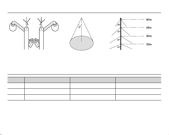
1. Installing a lightening conductor
a) Protection area
b) Protected angle
(Depending on the height of the
lightening conductor)
2. Camera grounding
No Distinguished by Standard Note
1
2
3
The purpose of the camera grounding
Installing the lightening conductor and grounding the camera chassis prevent the CCTV camera from the lightning
strikes. When installing the CCTV camera outside, avoid the damages form the lightning strikes by using the lightening
conductor and camera grounding.
Grounding method The class 3 CCTV product
Thickness of the Grounding wire 1.6mm2
Ground resistance
100Ω

contents
OVERVIEW
02 Overview
ENG
02
FEATURES
03
INSTALLATION
04
SPECIFICATIONS
11
03 Features
04 Package
04 Parts & Description
05 Things to keep in mind during installation
and Use
05 Connect the auto iris lens connector
06 Install the lensr
06 Adjust the back focus
07 Connect the cables and check the operation
11 Specifications
01

overview
It is a high-resolution box camera that has implemented the horizontal resolution of 540 lines by taking advantage of the
Digital Signal Processing and OLPF technologies.
In mechanical fluorescent lightning conditions, you can experience so-called “color rolling” if you have
•
installed the manual iris lens on the camera and positioned the function switch from ELC to ON. In this
case, connect the camera to the power source (AC) and position the L/L switch on the rear panel to EXT.
(NTSC: 60Hz, PAL: 50Hz)
- What is Color Rolling?
This occurs because the mechanical fluorescent lightning blinks from power frequencies, where the
color temperature input to the camera is not certain so the color on the screen changes irregularly
(red, blue, yellow, etc).
- This problem can be solved by using the Line Lock function or the Auto Iris Lens.
02

features
ENG
High Color Sensitivity
Resolution
Excellent Back Light
Compensation
Digital Power Synchronization
Dynamic CCD Defect
Compensation
The camera adopts the latest 1/3” super-HAD IT CCD to get the
benefit of high color sensitivity.
Introduces Full Digital Image Processing from the digital signal
technology to implement a high-resolution image.
This will guarantee a sharp image by compensating for the back light
even if the sunlight or bright lightening reflects against the subject.
Adopts the full digital line lock system to enable you to adjust the
vertical synchronization of the camera, an enhancement of manipulation
and reliability.
Uses advanced technology to compensate CCD defects in any mode, to
give clear, sharp and noise-free images, even in low contrast scenes.
03
installation
In this chapter, we will provide you with general
instructions for product installation and preferred places
as well as considerations before installation. Now, let’s
install the camera and connect necessary cables.)
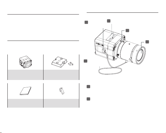
Package
You must check that all the components and accessories
listed below are included in the product package.
Camera
User’s guide Auto Iris Lens Connector
04
Camera Holder
(Mount Adaptor) screw x2
Parts & Description
1
3
Auto Iris Lens
5
Auto Iris Lens
Control Cable
1
Mount Adaptor Holes
Used to fix the mount adaptor with a screw if you
want to mount the camera on the bracket.
2
Auto Iris Lens (Optional)
A lens to be installed on the camera
- If the camera gets dirty on the surface of the lens,
Mount Adaptor Holes
Connector
apply ethanol to the provided tissue or a dry cloth
and wipe it out.
4
Flange Back
Adjustable Ring
2
Auto Iris
Lens

3
Auto Iris Lens Connector
Provides power source and control/ DC signal with
iris lens that are required to control the iris of the lens
4
Flange Back Adjustable Ring
Used to adjust the back focus of the camera.
5
Auto Iris Lens Control Cable
Transfers the control signal from the camera to the
iris lens.
Things to keep in mind during
installation and Use
Do not disassemble the camera on your own.
•
Always be careful when handling the camera.
•
Do not strike the camera by your fists or shake
it. Please be careful not to be careless when
storing and operating it.
Do not place or operate the camera in any wet
•
environment such as rain or wet surfaces.
Do not clean the camera with rough sandpaper.
•
Please always use a dry cloth when cleaning it.
Put the camera in a cool area free from direct
•
sunlight. Otherwise, the camera may be damaged.
Connect the auto iris lens connector
Remove the sheath round the iris control cable and
connect it to each of the auto iris lens connector as
described below.
Rib
Pin3
Pin1
Pin4
Pin2
Pin Number DC Control Type
1 Damp(–)
2 Damp(+)
3 Drive(+)
4 Drive(–)
05
ENG
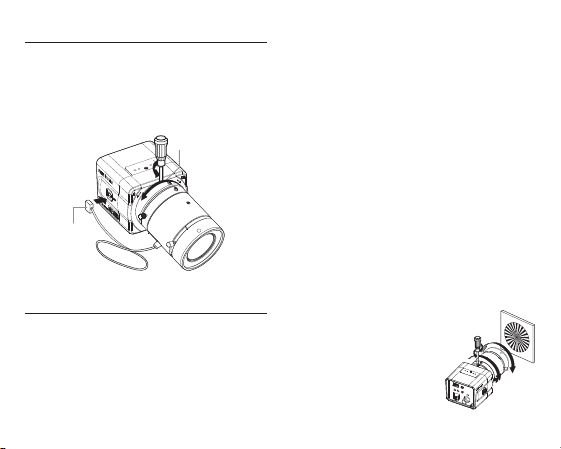
Install the lens
Loosen the single screw on the adjustable ring of the
flange back by turning it anti-clockwise and turn the
ring in the “C” direction (anti-clockwise) to the end.
Otherwise, it can cause damage to the internal image
sensor or the lens when you install the lens on the
camera.
Iris Control
Cable
C direction
Adjust the back focus
The back focus of a camera is predefined by the
factory default. However, some models are out of focus
depending on the lens type. If your camera is out of
focus, follow the instructions below to adjust the back
focus. The following is the procedure used to set the
proper back focus point in fixed focus lenses.
06
Lens without zooming feature
1.
Capture a sharp subject (with a grid pattern) more than
10m apart and adjust the focus ring to the infinity (∞).
2. Adjust the adjustable ring of the flange back so that
you can capture the sharpest image.
3. Fasten the screw of the adjustable ring of the flange
back.
Lens with zooming feature
1. Capture a sharp subject (with a grid pattern) 3-5m
apart and adjust the zoom in the TELE (zooming)
direction as possible and also adjust the focus ring so
that you can capture the sharpest image.
2. Adjust the zoom in the WIDE direction as possible and
turn the adjustable ring of the flange back so that you
can capture the sharpest image.
3. Repeat 1 and 2 above 2-3 times to match the focus
from the ZOOM TELE side with that from the ZOOM
WIDE side.
4. Fasten the screw of the adjustable ring of the flange
back.
- If you darken the image before
adjusting the focus by attaching
the ND filter to the front of the lens,
you can get a sharper focus.

Connect the cables and check the operation
VIDEO IN Terminal on
the rear of moniter
BNC Cable
VIDEO OUT Terminal
1. Connect one end of the BNC cable to the VIDEO OUT
port of the monitor.
2. Connect the other end of the BNC cable to the VIDEO
In port.
3. Connect the camera to the power adaptor. Use a
slotted flat (-) screwdriver to connect one end of the
two-line power adaptor to the DC/AC IN port of the
camera. (GND: marked with a white line on the cable)
- You can plug in to a power outlet regardless of the
polarity for both AC 24V and DC 12V adaptor.
AC24V/DC12V (SCC-B1311, B1311P)
AC220V ~ 240V (SCC-B1011P)
ENG
07

AC24V/DC12V (SCC-B1311, B1311P)
5
3
4
7
L/L
AC 220-240V
VIDEO OUT
GND
1. ELC
3. FL
2. BLC
4. AWB
INT EXT
2
6
8
1
AC220V ~ 240V (SCC-B1011P)
08
1
Power Port
Port that is connected to the power (adaptor) cable.
- For SCC-B1311, B1311P
Connects to AC 24V or DC 12V.
- For SCC-B1011P
Connects to AC220V ~ 240V.
2
Power Indication LED
If properly supplied with power, the LED turns on.
3
Vertical Synchronization Phasing Switch (Left)
Used to adjust the vertical synchronization phasing.
If pressed, the vertical synchronization moves to the
left.
4
Vertical Synchronization Phasing Switch
(Right)
Used to adjust the vertical synchronization phasing.
If pressed, the vertical synchronization moves to the
right.
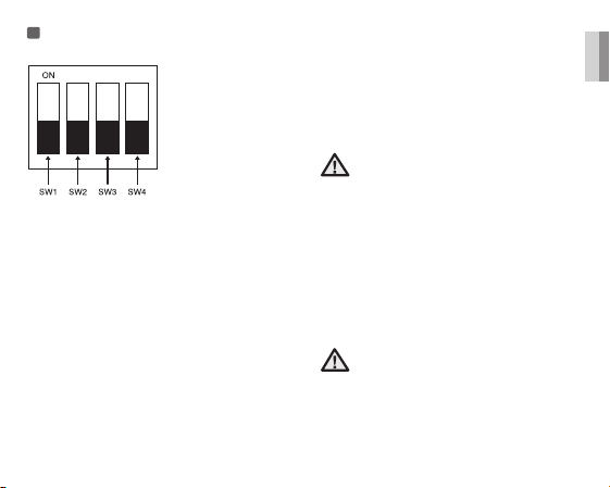
5
FUNCTION SWITCH-1
1. ELC
2. BLC
3. FL(Flickerless)
4. AWB
SW1(ELC)
Use this for the manual iris lens. If set to ON, the electronic
shutter speed varies between 1/60 and 1/120,000 second
to keep the screen brightness proper. However, you must
position this switch to OFF if you are using the auto iris
lens (DC control type). Because, in this mode, the camera
can show the color rolling effect when operating under the
mechanical fluorescent lightning. If this happens, apply the
AC power and set the L/L to "EXT". (NTSC: 60Hz, PAL:
50Hz)
SW2(BLC)
Use to compensate for a display that is too bright or too
dark when indoor lighting or windows reflects against the
subject. Set to ON for these conditions.
SW3(FL)
It is an anti-flicker system that prevents the flickering of the
image due to mismatch between the vertical sync frequency
and the on-off frequency of the lightning.
It is used when the camera and broadcasting system within
its own region do not match each other. If set to ON, the
electronic shutter speed stays at either 1/100sec (NTSC) or
1/120sec (PAL).
If SW1 (ELC) is set to ON, the anti-flicker system
does not work even if SW3 is positioned to ON.
ENG
SW4(AWB)
ON(ATW): It automatically adjusts the image color
according to the temperature change of the
lightning color. Under a very irregular lightning
condition (such as car headlight), if set to ON,
it captures a subject normally (white).
OFF(AWC): It remembers the normal color temp switch
with the OFF to operate at a certain white
balance level.
Note that AWB can cause an error in the following
conditions:
- If a big subject of a uniform color with a high
saturation exists in the center of the screen or
if few part of the image is in white.
- If the lightning is made of special material like
sodium.
09
6
FUNCTION SWITCH-2
If multiple cameras are connected to such as a
sequential switcher in auto switch mode, the camera
in the internal sync mode occurs a skip every time it
moves to other scene. However, this can be solved by
positioning the L/L switch to EXT and using the level bar
to adjust the vertical sync phasing.
- INT: It operates in the internal synchronization mode.
- EXT: it operates in the power synchronization mode.
※
If your camera uses DC 12V for power source,
it operates in the internal mode regardless of the
position (EXT/INT) of the L/L switch.
10
7
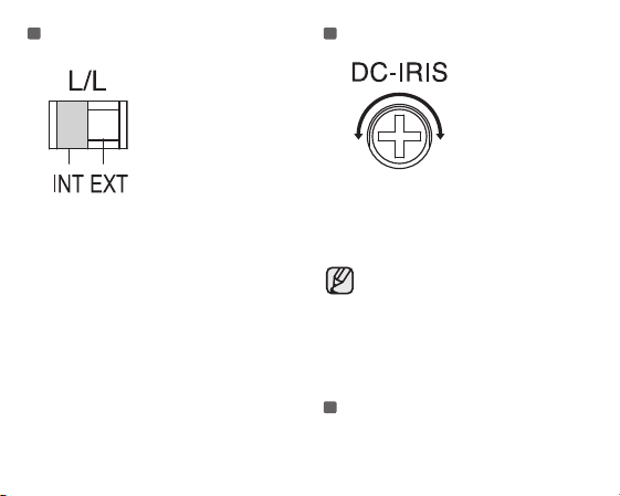
DC IRIS Level Bar
Used to adjust the iris level of this level bar using a
screwdriver.
- Anti-clockwise: Decreases the luminance level.
- Clockwise: Increases the luminance level.
- The IRIS range of the DC lens is about between
80IRE and120IRE. In other words, the DC lens
adopts a variable range limitation system, rather
than IRIS Full Open/Close system.
- Depending on the type of the lens used that
allows setting the value below 75 IRE may cause
IRIS hunting. Therefore, make sure that the
range is set to an appropriate level (higher than
80 IRE).
8
Video Out Port
Connected to the Video Out port of a monitor.
The video signal is output via this port.

제제제제제제제제specifications
SCC-B1311
Item Description
Product Type
Broadcasting
System
Imaging Device
Number of Effective
Pixels
Scanning 525 Line, 2:1 interlace
Line Frequency
Synchronous Mode
Horizontal
Resolution
S/N Ratio
Minimum Subject
Illumination
ALC/ELC
Surveillance Camera
NTSC STANDARD SYSTEM
1/3”IT, S-HAD-CCD
768(H) x 494(V)
INTERNAL : 15,734Hz(H)
59.94 Hz(V)
LINELOCK : 15,750Hz(H)
60 Hz(V)
INTERNAL
LINE LOCK (AC 24V)
540 TV Lines
Approx. 50dB
0.40Lux (F1.2, 50IRE)
0.24Lux (F1.2, 30IRE)
0.12Lux (F1.2, 15IRE)
ALC: DC IRIS LENS Only
ELC: Electronic Shutter Iris
(max. 1/120Ksec)
Item Description
FL(FLICKERLESS) OFF/ON
Lens Manual/Auto Iris DC Lens
Lens Mount
AWB(Auto White
Balance)
BLC(Back Light
Compensation)
AGC AUTO
Signal Out
Power
Power Consumption
Operation
Temperature
Operation Humidity
Dimension(mm) 68(W) x 55(H) x 77.1(D)
Weight 220 g
C, CS Lens Adaptable
ON : ATW
OFF : AWC
ON/OFF
COMPOSITE VIDEO OUT
1V p_p 75Ω / BNC
AC24V ±10%(60Hz±0.3Hz),
DC12V+10%~-5%
Approx. 3.0 Watts
-10°C ~ +50°C
~90%
ENG
11

SCC-B1311P, B1011P
Item Description
Product Type
Broadcasting
System
Imaging Device
Number of
Effective Pixels
Scanning 625 Line, 2:1 interlace
Line Frequency
Synchronous
Mode
Horizontal
Resolution
S/N Ratio
Minimum
Subject
Illumination
ALC/ELC
FL(FLICKERLESS)
Lens Manual/Auto Iris DC Lens
Surveillance Camera
PAL STANDARD SYSTEM
1/3”IT, S-HAD-CCD
752(H) x 582(V)
INTERNAL : 15,625Hz(H) 50 Hz(V)
LINE LOCK : 15,625Hz(H) 50 Hz(V)
INTERNAL
LINE LOCK (AC 24V)
540 TV Lines
Approx. 50dB
0.40Lux (F1.2, 50IRE)
0.24Lux (F1.2, 30IRE)
0.12Lux (F1.2, 15IRE)
ALC : DC IRIS LENS Only
ELC : Electronic Shutter Iris
(max. 1/120Ksec)
OFF/ON
12
Item Description
Lens Mount
AWB(Auto White
Balance)
BLC(Back Light
Compensation)
AGC AUTO
Signal Out
Power
Power
Consumption
Operation
Temperature
Operation
Humidity
Dimension(mm)
Weight
C, CS Lens Adaptable
ON : ATW
OFF : AWC
ON/OFF
COMPOSITE VIDEO OUT
1V p_p 75Ω / BNC
SCC-B1311P:
AC24V ±10%(50Hz±0.3Hz),
DC12V+10%~-5%
SCC-B1011P :
AC220V~AC240V(50Hz±0.3Hz)
SCC-B1311P: approx. 3.0 Watts
SCC-B1011P: approx. 3.5 Watts
-10°C ~ +50°C
~90%
SCC-B1311P:
68(W) x 55(H) x 77.1(D)
SCC-B1011P:
65(W) x 55(H) x 130.5(D)
SCC-B1311P: 220 g
SCC-B1011P: 450 g

Correct Disposal of This Product
(Waste Electrical & Electronic Equipment)
(Applicable in the European Union and other European countries with separate
collection systems)
This marking shown on the product or its literature, indicates that it should not be
disposed with other household wastes at the end of its working life. To prevent
possible harm to the environment or human health from uncontrolled waste disposal,
please separate this from other types of wastes and recycle it responsibly to promote
the sustainable reuse of material resources.
Household users should contact either the retailer where they purchased this product,
or their local government ofce, for details of where and how they can take this item for
environmentally safe recycling.
Business users should contact their supplier and check the terms and conditions of the
purchase contract. This product should not be mixed with other commercial wastes for
disposal.

Memo

SCC-B1311(P)
SCC-B1011P
Цветная цифровая камера
Руководство по эксплуатации
Удивительные возможности
Благодарим вас за приобретение данного устройства Samsung.
Для получения наилучшего обслуживания зарегистрируйте свое устройство по адресу:
www.samsung.com/global/register
RUS

техника безопасности
ВНИМАНИЕ
ОПАСНОСТЬ ПОРАЖЕНИЯ ЭЛЕКТРИЧЕСКИМ ТОКОМ. НЕ ОТКРЫВАТЬ
ВНИМАНИЕ: ВО ИЗБЕЖАНИЕ ПОРАЖЕНИЯ ЭЛЕКТРИЧЕСКИМ ТОКОМ, НЕ СНИМАЙТЕ ЗАДНЮЮ
КРЫШКУ. ВНУТРИ НЕТ ДЕТАЛЕЙ, ОБСЛУЖИВАЕМЫХ ПОЛЬЗОВАТЕЛЕМ. ДЛЯ ТЕХНИЧЕСКОГО
ОБСЛУЖИВАНИЯ ОБРАЩАЙТЕСЬ К КВАЛИФИЦИРОВАННОМУ СПЕЦИАЛИСТУ.
Этот символ обозначает, что внутри устройства имеется опасное напряжение, которое может привести к
поражению электрическим током.
Этот символ указывает, что в документации на изделие имеется важная инструкция по его использованию или
обслуживанию.
ПРЕДУПРЕЖДЕНИЕ
ПРЕДУПРЕЖДЕНИЕ
Во избежание повреждений, следствием которых может быть пожар или поражение электрическим током, не допускайте
•
попадания данного изделия под дождь или в условия высокой влажности.
1. Пользуйтесь только стандартным блоком питания, который указан в листе спецификаций. Использование любого
другого блока питания может привести к пожару, поражению электрическим током или к повреждению изделия.
2. Неправильное подключение блока питания или замена батареи может привести к взрыву, пожару,
поражению электрическим током или к повреждению изделия.
3. Не подключайте несколько видеокамер к одному блоку питания. Превышение нагрузочной способности блока
питания может привести к его перегреву или к пожару.
4. Надежно вставьте вилку сетевого шнура в розетку сети переменного тока. Ненадежное подключение может
привести к пожару.

5. При установке видеокамеры закрепите ее прочно и надежно. Падение видеокамеры может привести к травме.
6. Не кладите сверху на видеокамеру токопроводящие предметы (например, отвертки, монеты и другие металлические
предметы) и не ставьте на нее наполненные водой сосуды. Невыполнение этих требований может привести к пожару,
поражению электрическим током или к травмам в результате падения этих предметов.
7. Не устанавливайте изделие во влажных, запыленных или покрытых копотью помещениях. Невыполнение этого
требования может привести к пожару или к поражению электрическим током.
8. Если вы почувствуете необычный запах или обнаружите дым, выходящий из изделия, прекратите эксплуатацию.
В этом случае следует немедленно отсоединить изделие от источника питания и связаться с сервисным центром.
Продолжение эксплуатации изделия в таком состоянии может привести к пожару или к поражению электрическим
током.
9. При обнаружении неисправности в изделии свяжитесь с ближайшим сервисным центром. Никогда не разбирайте
данное изделие и не вносите изменений в его конструкцию. (Компания SAMSUNG не несет ответственности за
проблемы, возникшие в результате внесения изменений в конструкцию изделия или попыток самостоятельно
выполнить ремонт изделия).
10. При чистке изделия не разбрызгивайте на него воду. Это может привести к пожару или к поражению электрическим
током.
ВНИМАНИЕ
1. Не роняйте на изделие никакие предметы и не ударяйте по нему. Не устанавливайте изделие в местах с сильной
вибрацией или вблизи источников магнитного поля.
2. Не устанавливайте изделие в местах с высокой (выше 50°С) или низкой (ниже -10°С) температурой или с высокой
влажностью. Это может привести к пожару или поражению электрическим током.
3. Если вы хотите переместить ранее установленное изделие на новое место, отключите перед этим питание изделия.
4. Во время грозы отсоедините шнур питания видеокамеры от розетки сети переменного тока. Невыполнение этого
требования может привести к пожару или к повреждению изделия.
5. Устанавливайте изделие так, чтобы на него не падал прямой солнечный свет и чтобы рядом не было источников,
излучающих тепло. Это может привести к пожару.
6. Изделие должно устанавливаться в помещении с хорошей вентиляцией.
7. Избегайте направлять видеокамеру прямо на очень яркие объекты, например, на солнце, так как это может привести к
повреждению матрицы ПЗС, формирующей изображение.
8. Изделие должно быть защищено от воздействия капель или брызг воды и на него нельзя помещать наполненные водой
сосуды, например, вазы с цветами.
9. Вилка сетевого шнура используется в качестве отсоединяющего от питания устройства и к ней всегда должен быть
обеспечен легкий доступ.
RUS

важные правила техники
1. Прочтите эти правила.
2. Сохраните эти правила.
3. Принимайте во внимание все предупреждения.
4. Следуйте всем правилам.
5. Не используйте изделие вблизи воды.
6. Чистите изделие только сухой салфеткой.
7. Не загораживайте никакие вентиляционные отверстия. Выполните установку изделия в соответствии с
инструкциями изготовителя.
8. Не устанавливайте изделие рядом с источниками тепла, такими, как радиаторы, решетки системы отопления, или
другими устройствами, которые генерируют тепло (включая усилители).
9. В целях безопасности не отказывайтесь от использования вилок поляризованного или заземляющего типа.
Вилка поляризованного типа имеет два ножевых контакта, один из которых шире другого. Вилка заземляющего
типа имеет два контакта и третий заземляющий штырь. Широкое лезвие третьего заземляющего штыря
предусмотрено для вашей безопасности. Если вилка поставляемого вместе с аппаратом шнура питания не
подходит для вашей розетки, попросите опытного электрика заменить старую розетку.
10. Не наступайте на шнур питания и не допускайте его защемления, особенно вблизи от штепсельной вилки, в
месте подключения к розетке и там, где шнур выходит из изделия.
11. Пользуйтесь только теми приспособлениями/ принадлежностями, которые рекомендованы изготовителем.
12. Используйте изделие только с тележкой, кронштейном, штативом, держателем или подставкой,
предусмотренными изготовителем или поставляемыми в комплекте с изделием.
13. Перед перемещением изделия отсоедините его от электросети. Если используется тележка, соблюдайте
осторожность при перемещении тележки с изделием, чтобы избежать повреждения изделия или травмы при
опрокидывании.
14. Все работы, связанные с техническим обслуживанием изделия, должны выполняться квалифицированными
специалистами по техническому обслуживанию. Обслуживание изделия требуется выполнять, когда изделие
получило какое-либо повреждение, например, был поврежден его шнур питания или вилка шнура питания, внутрь
изделия попала жидкость или посторонние предметы, изделие подверглось воздействию дождя или влаги,
изделие не работает должным образом, а также после падения изделия.
제제제제제제제제제제제제

установка цифровой камеры наружного наблюдения
(CCTV)
1
Установка грозового разрядника и системы заземления.Отделите систему
заземления.
2
Установка камеры и системы заземления.Используйте надежное
заземление (сопротивление заземления: 100
3
Класс 3. (Заземление камеры) Отделите систему заземления от грозового
разрядника.
➧
Ω
или меньше.) (Класс 3)
RUS
Поверхность
Можно использовать материалы, снижающие
сопротивление заземления вокруг заземляющих
Сопротивление заземления:100Ω или меньше.
стержней.
< Схема заземления >
Диаметр:
300Φ
Более 0,75 м
Глубина заземления: Не менее 3 м.
(Максимум один метр)

1. Установка грозового разрядника
a) Защищенная область
б) Защищенный угол
(Зависит от высоты грозового
разрядника)
2. Заземление камеры
Нет
Отличительныеособенности
1
2
3
Цель заземления камеры
Установка грозового разрядника и заземление корпуса камеры предохраняют ее от разрядов молнии. При
установке камеры CCTV снаружи здания используйте грозовой разрядник и систему заземления, чтобы
избежать повреждения камеры в результате попадания разрядов молнии.
Способ заземления Класс 3 Камера CCTV
Толщина провода заземления
Сопротивление заземления
Стандарт Примечание
1,6 мм2
100Ω

содержание
ОБЗОР
02 Обзор
02
ХАРАКТЕРИСТИКИ
03
УСТАНОВКА
04
ТЕХНИЧЕСКИЕ ХАРАКТЕРИСТИКИ
11
03 Характеристики
04 Комплект поставки
04 Компоненты камеры
05 Меры предосторожности при установке и
эксплуатации
05 Подключите разъем объектива с автоматической
диафрагмой
06 Установка объектива
06 Регулировка заднего фокуса
07 Подсоединение кабелей и проверка работы
11 Технические характеристики
RUS
01

обзор
Камера высокого разрешения (540 линий по горизонтали), в которой используются преимущества цифровой
обработки сигналов (DSP) и технологии OLDF.
В условиях люминесцентного освещения, если на камеру установлен объектив с ручной
•
регулировкой диафрагмы, и переключатель ELC установлен в положении ON (ВКЛ), может
наблюдаться так называемая "подкраска изображения". В таком случае подключите камеру к
сети переменного тока и установите переключатель L/L (СИНХРОНИЗАЦИЯ) на задней панели
в положение EXT (ВНЕШНЯЯ). (NTSC: 60 Гц, PAL: 50 Гц)
- Что такое “подкраска изображения”?
Она возникает из-за того, что люминесцентные лампы мерцают с частотой сети
переменного тока, из-за чего температура цвета на входе в камеру является
непостоянной, так что цвет на экране начинает меняться нерегулярным образом (красный,
голубой, желтый и т.д.)
- Эта проблема решается путем использования функции Line Lock (СИНХРОНИЗАЦИЯ)
или объективов с автоматической регулировкой диафрагмы.
02

характеристики
Высокая цветовая
чувствительность
Разрешение
Отличная компенсация
встречной засветки
Цифровая синхронизация от
сети переменного тока
Компенсация динамических
дефектов CCD
В камере установлена новейшая 1/3”матрица super-HAD IT CCD
с высокой цветовой чувствительностью.
Технология полностью цифровой обработки сигнала позволяет
добиться высокого разрешения изображений.
Гарантирует четкое изображение за счет компенсации встречной
засветки даже в том случае, если позади объекта находится
солнце или другой источник яркого света.
Полностью цифровая система синхронизации от сети
переменного тока позволяет синхронизировать кадровую
развертку с частотой сети - что удобно и надежно.
Передовая технология для компенсации динамических дефектов
матрицы CCD в любом режиме, что позволяет получать ясное и
четкое изображение без каких-либо шумов даже в условиях низкой
контрастности.
RUS
03

установка
В этом разделе содержатся общие сведения об установке камеры
и предпочитаемых местах установки а также сообщается, какие
действия следует выполнить до установки. Итак, приступим к
установке камеры и подсоединению необходимых кабелей.
Компоненты камеры
3
Разъем для подключения
объектива с автоматической
диафрагмой
Комплект поставки
Проверьте, на месте ли все перечисленные ниже компоненты и
принадлежности.
5
Кабель управленияобъектива
с автоматической диафрагмой
1
Камера
Руководство
пользователя
Держатель камеры
(основание) 2 крепежных
винта
Разъем для
подключения
объектива с
автоматической
диафрагмой
Отверстия держателя камеры
Используются для крепления основания в случае
установки камеры на крепежную скобу. Объектив с
автоматической
2
диафрагмой (Опция)
Объектив для камеры
- В случае загрязнения линзы объектива протрите
ее кусочком ткани, смоченном в этиловом спирте
или сухой тканью.
04
1
Отверстия держателя
камеры
4
Кольцо регулировки
заднего фокуса
2
Объектив с
автоматической
диафрагмой

3
Разъем для подключения объектива с
автоматической
диафрагмойДля подвода питания и управления
диафрагмой объектива с помощью сигнала
постоянного тока
4
Кольцо регулировки за
днего фокусаДля настройки заднего фокуса камеры.
5
Кабель управления объектива с автоматической
диафрагмойПо этому кабелю с камеры на объектив
передается сигнал управления диафрагмой.
Меры предосторожности при
установке и эксплуатации
Не пытайтесь самостоятельно разбирать камеру.
•
При обращении с камерой всегда проявляйте
•
осторожность. Не бейте камеру кулаком и не трясите ее.
Соблюдайте все необходимые меры предосторожности
при хранении и эксплуатации камеры.
Не оставляйте и не включайте камеру под дождем или
•
во влажных местах.
Не очищайте камеру с помощью наждачной бумаги.
•
Чистите камеру только с помощью сухой материи.
Держите камеру в прохладном месте, не допуская
•
попадания на нее прямых солнечных лучей. В
противном случае камера может быть повреждена.
Подключите разъем объектива с
автоматической диафрагмой
Снимите оболочку с кабеля управления
диафрагмой и подсоедините его к разъемам
управления диафрагмой, как показано на рисунке
ниже.
контакта
Ребро
Контакт3
Контакт1
Контакт4
Контакт2
Номер
Тип управления посредством
1 Демпфирующий (-)
2 Демпфирующий (+)
3 Drive (+)
4 Drive (-)
постоянного тока
05
RUS

Установка объектива
Ослабьте винт на кольце регулировки заднего фокуса, повернув
его против часовой стрелки, после чего поверните само кольцо
в направлении метки "С" (против часовой стрелки) до упора. В
противном случае при установке объектива на камеру можно
повредить чувствительную матрицу камеры или сам объектив.
Кабель управления
автоматической
диафрагмой
В направлении "С"
Регулировка заднего фокуса
Регулировка заднего фокуса камеры выполняется на заводеизготовителе. Однако для некоторых типов объективов фокус
может быть не отрегулирован долж ным образом. В этом случае
следует выполнить регулировку заднего фокуса, как описано
ниже. Далее описано, как выполняется такая регулировка для
объективов с постоянным фокусным расстоянием.
Объективы с постоянным фокусным расстоянием (без
трансфокатора)
1. Наведите камеру на объект с контрастными деталями (с сеткой),
расположенный на расстоянии более 10 м, и установите кольцо
регулировки фокуса на "бесконечность" (∞).
2. Вращая кольцо регулировки заднего фокуса, добейтесь
максимальной резкости изображения.
3. Затяните стопорный винт, фиксирующий положение кольца
регулировки заднего фокуса.
Объективы с переменным фокусным расстоянием
(с трансфокатором)
1. Наведите камеру на объект с контрастными деталями (с сеткой),
находящийся на расстоянии 3-5 м от камеры, и отведите
рычаг трансфокатора в положение TELE (ДАЛЬШЕ) до упора;
затем, вращая кольцо регулировки заднего фокуса, добейтесь
максимальной резкости изображения.
2. Отведите рычаг трансфокатора в положение WIDE (БЛИЖЕ) до
упора и, вращая кольцо регулировки заднего фокуса, добейтесь
максимальной резкости изображения .
3. Повторите описанные в пунктах 1 и 2 операции 2-3 раза,
чтобы добиться одинаковой фокусировки при установках
трансфокатора в положениях TELE (ДАЛЬШЕ) и WIDE (БЛИЖЕ).
4. Затяните стопорный винт, фиксирующий положение кольца
регулировки заднего фокуса.
- Затемнив изображениес помощью
фильтра ND перед настройкой фокуса,
можно добиться более резкого фокуса.
06

Подсоединение кабелей и проверка работы
Вход видеосигнала
(VIDEO IN)на задней
панели монитора
Кабель с
разъемами BNC
Видеовыход (VIDEO
OUT)
1. Подсоедините один конец кабеля BNC к разъему VIDEO
OUT (ВИДЕОВЫХОД) камера.
2. Подсоедините другой конец кабеля BNC к разъему
VIDEO IN (ВИДЕОВХОД) монитора.
3. Подключите камеру к адаптеру питания. С помощью
отвертки с плоским наконечником (-) подсоедините два
провода адаптера питания к разъему DC/AC IN камеры.
(ЗАЗЕМЛЕНИЕ: белый провод кабеля)
- Можно использовать источник питания 24 В
переменного тока или 12 В постоянного тока
(полярность подключения не имеет значения).
Камера , работающая от источника питания
переменного тока 24 В / постоянного тока 12 В
(SCC-B1311, B1311P)
Камера , работающая от источника питания
переменного тока 220 В ~ 240 В (B1011P)
RUS
07

Камера , работающая от источника питания
5
3
4
7
L/L
AC 220-240V
VIDEO OUT
GND
1. ELC
3. FL
2. BLC
4. AWB
INT EXT
2
6
8
1
переменного тока 24 В / постоянного тока
12 В (SCC-B1311, B1311P)
Камера , работающая от источника питания
переменного тока 220 В ~ 240 В (SCCB1011P)
08
1
Разъем питанияРазъем
для подключения питания (адаптера питания).
Камеры SCC-B1311, B1311P
-
подключаются к адаптеру питания переменного
тока 24 В или постоянного тока 12 В.
Камера SCC-B1011P
-
подключается к сети переменного тока 220 В ~
240 В.
2
Индикатор питания
Горит, если к камере подводится питание.
3
Регулировка фазы синхронизации кадровой
развертки (влево)
При нажатии фаза синхронизации смещается
влево.
Регулировка фазы синхронизации кадровой
4
развертки ( вправо )
При нажатии фаза синхронизации смещается
вправо.

5
ПЕРЕКЛЮЧАТЕЛЬ ФУНКЦИЙ-1
1. ELC
2. BLC
3. FL(Flickerless)
4. AWB
П
ЕРЕКЛЮЧАТЕЛЬ 1(ELC )
Используется в случае установке объектива с ручной регулировкой
диафрагмы. В положении ON (ВКЛ) скорость затвора меняется в
пределах от 1/60 до 1/120000 сек с целью обеспечения должной
яркости изображения. Следует переключить его в положение
OFF (ВЫКЛ), если у вас установлен объектив с автоматической
регулировкой диафрагмы (Тип управления DC ). Это делается
для предотвращения эффекта подкраски изображения в условиях
люминесцентного освещения. Если это наблюдается, подключите
камеру к источнику переменного тока и установите (L/L) в
положение "EXT". (NTSC: 60 Гц, PAL: 50 Гц)
ПЕРЕКЛЮЧАТЕЛЬ 2(BLC)
Используется для компенсации избытка или недостатка
освещенности, когда позади объекта находится лампа освещения
или окно. В таком случае установите его в положение ON (ВКЛ).
Переключатель системы, предотвращающей появление мерцания
в случае несоответствия частоты кадровой развертки и частоты
мерцания источника освещения.
Используется в случае, когда система NTSC используется
в регионе с частотой электросети 50 Гц или система PAL
используется в регионе с частотой электросети 60 Гц. В положении
ON (ВКЛ) скорость затвора устанавливается равной либо 1/100
сек (NTSC), или 1/120 сек (PAL).
Если ПЕРЕКЛЮЧАТЕЛЬ 1 (ELC) установлен в положение
ON (ВКЛ), система подавления мерцания не работает
даже в том случае, когда ПЕРЕКЛЮЧАТЕЛЬ 3 установлен
в положение ON (ВКЛ).
ПЕРЕКЛЮЧАТЕЛЬ 4(AWB)
ON (ATW)(ВКЛ): Цвет экрана регулируется автоматически
OFF (AWC)(ВЫКЛ): При переключении в положение OFF (ВЫКЛ)
в соответствии с изменением цветовой
температуры освещения. При установке
переключателя в положение ON (ВКЛ) камера
достаточно хорошо захватывает изображение
даже в условиях очень нерегулярного освещения
(такого, как свет фар автомобилей).
Учтите, что в перечисленных ниже случаях может
произойти ошибка подстройки цвета:
- Если в центре экрана находится крупный одноцветный
объект с высокой насыщенностью цвета, либо на
экране почти нет белого цвета.
- Если используется особый источник света, такой как
натриевая лампа
ПЕРЕКЛЮЧАТЕЛЬ 3 (FL)
RUS
камера запоминает цветовую температуру
освещения.
.
09

6
ПЕРЕКЛЮЧАТЕЛЬ ФУНКЦИЙ-2
7
Регулятор уровня сигнала управления
диафрагмой (DC)
Если несколько камер подключены к последовательному
видеокоммутатору в автоматическом режиме, то может
происходить подергивание изображения во время переключения
на камеру, работающую в режиме внутренней синхронизации. Эта
проблема может быть решена путем установки переключателя
L/L (СИНХРОНИЗАЦИЯ) в положение EXT (ВНЕШНЯЯ) и
использования рычажка регулировки фазы синхронизации
кадровой развертки.
- INT (ВНУТРЕННЯЯСИНХРОНИЗАЦИЯ):
Камера работает в режиме утренней онизации.
- EXT (ВНЕШНЯЯ СИНХРОНИЗАЦИЯ):
Камера работает в режиме синхронизации от сети переменного
тока.
※
При использовании адаптера питания постоянного тока 12
В камера работает в режиме внутренней синхронизации
(EXT/INT) независимо от положения переключателя L/L
(СИНХРОНИЗАЦИЯ).
10
С помощью крестовой отвертки можно регулировать уровень
сигнала управления диафрагмой.
- Против часовой стрелки: Снижение уровня яркости.
- По часовой стрелке: Повышение уровня яркости.
- Диапазон значений диафрагмы камеры приблизительно
равен 80 - 120 IRE. Иными словами, камера не способна
полностью открывать и закрывать диафрагму, а обладает
ограниченным диапазоном.
- Установка значения диафрагмы ниже 75 IRE может
приводить к колебаниям диафрагмы (в зависимости
от типа используемого объектива). Поэтому следует
убедиться, что уровень диафрагмы выставлен правильно
(выше 80 IRE).
8
Разъем видеовыхода
Соединяется с видеовходом монитора. Видеосигнал камеры
выводится через этот порт.

технические характеристики
Камера SCC-B1311
Характеристика Описание
Тип изделия Камера видеонаблюдения
Система вещания Стандарт NTSC
Матрица 1/3”IT, S-HAD-CCD
Количество
эффективных
пикселей
Развертка 525 строк, чересстрочная 2:1
Частота развертки
Режимы
синхронизации
Горизонтальное
разрешение
Отношение сигнал/
шум
Минимальная
освещенность
объекта
ALC/ELC
768 (Г) x 494 (В)
ВНУТРЕННЯЯ
СИНХРОНИЗАЦИЯ: 15734 Гц (Г)
СИНХРОНИЗАЦИЯ ОТ СЕТИ:
ВНУТРЕННЯЯОТ СЕТИ
ПЕРЕМЕННОГО ТОКА (24 В)
540 ТВ-строк
Около 50 дБ
0,40 люкс (F1.2, 50 IRE)
0,24 люкс (F1.2, 30 IRE)
0,12 люкс (F1.2, 15 IRE)
ALC: Регулировка диафрагмы
ELC: Регулировка скорости
59,94 Гц (В)
15750 Гц (Г)
60 Гц (В)
только с помощью
сигнала постоянного тока
затвора (максимум
1/120000 сек)
Характеристика Описание
FL (КОМПЕНСАЦИЯ
МЕРЦАНИЯ)
Объектив
Крепление
объектива
Автоматический
баланс белого (AWB)
Компенсация
встречной засветки
(BLC)
АРУ АВТО
Выходной сигнал
Питание
Потребляемая
мощность
Рабочая температура от -10°C до +50°C
Рабочая влажность ~90%
Габариты (мм) 68 (Ш) x 55 (В) x 77,1 (Д)
Масса 220 г
ВЫКЛ/ВКЛ
Объектив с ручной/
автоматической
диафрагмой
Регулируемые объективы
типа C, CS
ON (ВКЛ) : ATW
OFF (ВЫКЛ) : AWC
ВКЛ/ВЫКЛ
КОМПОЗИТНЫЙ
ВИДЕОВЫХОД1 В на
нагрузке 75Ω, разъем BNC
24 В переменного тока
±10% (60 Гц ± 0,3 Гц),
12 В постоянного тока
+10%~-5%
Около 3 Вт
11
RUS

Камеры SCC-B1311P, B1011P
Характеристика Описание
Тип изделия Камера видеонаблюдения
Система вещания Стандарт PAL
Матрица 1/3”IT, S-HAD-CCD
Количество
эффективных
пикселей
Развертка 625 строк, чересстрочная 2:1
Частота развертки
Режимы
синхронизации
Горизонтальное
разрешение
Отношение сигнал/
шум
Минимальная
освещенность
объекта
ALC/ELC
FL (КОМПЕНСАЦИЯ
МЕРЦАНИЯ)
Объектив
752 (Г) x 582 (В)
ВНУТРЕННЯЯ СИНХРОНИЗАЦИЯ:
15,625 Гц (Г) 50 Гц(В)
СИНХРОНИЗАЦИЯ ОТ СЕТИ:
15,625 Гц (Г) 50 Гц (В)
ВНУТРЕННЯЯОТ СЕТИ
ПЕРЕМЕННОГО ТОКА (24 В)
540 ТВ-строк
Около 50 дБ
0,40 люкс (F1.2, 50 IRE)
0,24 люкс (F1.2, 30 IRE)
0,12 люкс (F1.2, 15 IRE)
ALC : Регулировка диафрагмы
только с помощью сигнала
постоянного тока
ELC : Регулировка скорости затвора
(максимум 1/120000 сек)
ВЫКЛ/ВКЛ
Объектив с ручной/автоматической
диафрагмой
12
Характеристика Описание
Крепление
объектива
Автоматический
баланс белого
(AWB)
Компенсация
встречной засветки
(BLC)
АРУ АВТО
Выходной сигнал
Питание
Потребляемая
мощность
Рабочая
температура
Рабочая влажность ~90%
Габариты (мм)
Масса
Регулируемые объективы типа C,
CS
ON (ВКЛ) : ATW
OFF (ВЫКЛ) : AWC
ВКЛ/ВЫКЛ
КОМПОЗИТНЫЙ ВИДЕОВЫХОД1
В на нагрузке 75Ω, разъем BNC
Камера SCC-B1311P: 24 В
переменного тока ±10%(60 Гц
± 0,3 Гц), 12 В постоянного тока
+10%~-5%
Камера SCC-B1011P : 220~240 В
переменного тока (50 Гц ± 0,3 Гц)
Камера SCC-B1311P: около 3,0 Вт
Камера SCC-B1011P: около 3,5 Вт
от -10°C до +50°C
Камера SCC-B1311P: 68(Ш) x
55(В) x 77,1(Д)
Камера SCC-B1011P: 65 (Ш) x 55
(В) x 130,5 (Д)
Камера SCC-B1311P: 220 г
Камера SCC-B1011P: 450 г

Правильная утилизация данного устройства
(Утилизация электрического и электронного оборудования)
(Применяется в странах Европейского Союза и других странах Европы, в которых
существует система разделения отходов)
Данная маркировка, имеющаяся на изделии или указанная в руководстве,
указывает на то, что по истечении срока службы устройство не следует
выбрасывать с другим бытовым мусором. Чтобы предотвратить возможное
вредное воздействие на окружающую среду или здоровье человека от
неконтролируемой утилизации отходов, отделите его от другого вида отходов для
соответствующей переработки и повторного использования в качестве сырья.
Пользователю следует обратиться к продавцу в место приобретения изделия или
в местные органы управления для уточнения места и способа безопасной для
окружающей среды утилизации.
Корпоративным пользователям следует обратиться к поставщику и уточнить
условия договора о покупке. Данное изделие не следует утилизировать
Подлежит использованию по назначению
в нормальных условиях
Срок службы : 7 лет.
вместе с другими производственными отходами.

Memo

SCC-B1311(P)
SCC-B1011P
KOLOROWA KAMERA CYFROWA
Instrukcja użytkowania
wyobraź sobie możliwości
Dziêkujemy za zakup produktu firmy Samsung.
Aby uzyskaæ dostêp do pe³nego serwisu, zarejestruj produkt w witrynie
www.samsung.com/global/register
POL

środki ostrożności
UWAGA
NIEBEZPIECZEŃSTWO PORAŻENIA PRĄDEM. NIE OTWIERAĆ
UWAGA: ABY ZMNIEJSZYĆ RYZYKO PORAŻENIA PRĄDEM NIE USUWAĆ OBUDOWY (ANI CZĘŚCI
TYLNEJ). NIE MA CZĘŚCI PRZEZNACZONYCH DO NAPRAWY PRZEZ UŻYTKOWNIKA. NALEŻY
SKONTAKTOWAĆ SIĘ Z WYKWALIFIKOWANYM PERSONELEM SERWISU.
Ten symbol oznacza, że urządzenie pracuje pod wysokim napięciem, co może grozić porażeniem prądem
elektrycznym.
Ten symbol oznacza, że materiały dostarczone razem z urządzeniem zawierają ważne instrukcje
dotyczące obsługi i konserwacji urządzenia.
OSTRZEŻENIE
OSTRZEŻENIE
Aby zmniejszyć ryzyko pożaru lub porażenia prądem elektrycznym, nie należy wystawiać urządzenia na działanie
•
wody ani wilgoci.
1. Używaj tylko standardowego adaptera określonego w karcie charakterystyki technicznej. Stosowanie
wszelkich innych adapterów może spowodować pożar, porażenie prądem lub uszkodzić produkt.
2. Nieprawidłowe podłączenie zasilania lub wymiana baterii może spowodować wybuch, pożar, porażenie
prądem lub uszkodzić produkt.
3. Nie należy podłączać kilku kamer do jednego adaptera. Przekroczenie dopuszczalnego limitu może
spowodować nadmierną emisję ciepła lub pożar.
4. Przewód zasilający należy pewnie podłączyć do oprawy gniazda. Niepewne podłączenie może spowodować pożar.
5. Kamerę należy zamocować bezpiecznie i solidnie. Spadająca kamera może spowodować obrażenia ciała.

6. Na kamerze nie wolno ustawiać przedmiotów przewodzących prąd (np. śrubokrętów, monet,
przedmiotów metalowych itp.) ani pojemników napełnionych wodą. W przeciwnym wypadku może
dojść do uszkodzenia ciała w wyniku pożaru, porażenia prądem lub upadku przedmiotów.
7. Urządzenia nie należy montować w miejscach wilgotnych, zakurzonych ani pokrytych sadzą. W
przeciwnym razie może dojść do pożaru lub porażenia prądem.
8. Jeśli z urządzenia wydobywa się podejrzany zapach lub dym, należy zaprzestać jego używania. W
takim przypadku należy natychmiast odłączyć zasilanie i skontaktować się z centrum serwisowym.
Dalsza eksploatacja może w tym stanie doprowadzić do pożaru lub porażenia prądem.
9. Jeśli niniejszy produkt nie działa normalnie należy skontaktować się z najbliższym centrum serwisowym.
Niniejszego produktu nie wolno demontować ani modykować w żaden sposób. (SAMSUNG nie ponosi
odpowiedzialności za problemy spowodowane przez samodzielne modykacje lub próby napraw).
10. Podczas czyszczenia nie należy bezpośrednio spryskiwać wodą elementów produktu. W przeciwnym
razie może dojść do pożaru lub porażenia prądem.
UWAGA
1. Na produkt nie należy upuszczać przedmiotów ani powodować silnych wstrząsów.
Produkt należy umieszczać w miejscach, gdzie nie ma nadmiernych wibracji ani pola magnetycznego.
2. Produktu nie należy montować w miejscach, gdzie panują wysokie (ponad 50°C) lub niskie (poniżej -10°C)
temperatury, lub wysoka wilgotność. W przeciwnym razie może dojść do pożaru lub porażenia prądem.
3. W celu przeniesienia zamontowanego produktu należy najpierw wyłączyć jego zasilanie a następnie
przemieścić lub ponownie zamontować produkt.
4. W czasie burzy z wyładowaniami atmosferycznymi należy wyciągnąć wtyczkę z gniazda.
Pozostawienie podłączonego zasilania może wywołać pożar lub uszkodzenie produktu.
5. Produkt należy trzymać poza zasięgiem promieni słonecznych oraz źródeł promieniowania cieplnego.
Może to spowodować pożar.
6. Produkt należy montować w miejscu z dobrą wentylacją.
7. Nie należy kierować kamery bezpośrednio na bardzo jasne obiekty jak np. słońce, gdyż może to
uszkodzić czujnik obrazu CCD.
8. Urządzenie nie powinno być narażone na kapanie lub rozlanie płynu, nie należy na nim stawiać
przedmiotów wypełnionych cieczą np. wazonów.
9. Wtyczka sieci zasilającej stosowana jest jako urządzenie rozłączające, dlatego powinna być łatwo
dostępna przez cały czas.
POL

ważne zalecenia dotyczące bezpieczeństwa
1. Należy przeczytać poniższe zalecenia.
2. Należy zachować je do wglądu.
3. Należy przeczytać wszystkie ostrzeżenia.
4. Należy przestrzegać wszystkich zaleceń.
5. Nie używać urządzenia w pobliżu wody.
6. Czyścić wyłącznie suchą szmatką.
7. Nie blokować żadnych otworów wentylacyjnych. Montować zgodnie z instrukcją producenta.
8. Nie montować w pobliżu źródeł ciepła takich jak grzejniki, kratki nagrzewnic lub innych urządzeń (w
tym wzmacniaczy) emitujących ciepło.
9. Nie lekceważyć zabezpieczenia wynikającego ze stosowania wtyczek spolaryzowanych lub z
uziemieniem. Wtyczka spolaryzowana ma dwa bolce, z których jeden jest szerszy od drugiego.
Wtyczka z uziemieniem ma trzy bolce, z czego jeden jest uziemiający. Szerszy lub odpowiednio
trzeci bolec stosuje się w celu zapewnienia bezpieczeństwa. Jeśli dostarczona wtyczka nie pasuje do
gniazda, skontaktuj się z elektrykiem w celu wymiany przestarzałego gniazda.
10. Przewód zasilający przy wtyczkach, oprawach oraz w miejscach, gdzie wystają one z urządzenia
należy zabezpieczyć przed możliwością nadepnięcia lub przyciśnięcia.
11. Używać wyłącznie elementów dodatkowych/ akcesoriów zalecanych przez producenta.
12. Używać wyłącznie z wózkiem, stojakiem, trójnogiem lub stolikiem zalecanym przez producenta lub
sprzedawanym wraz z urządzeniem.
13.
Urządzenie należy odłączyć z sieci. Jeśli stosuje się wózek, należy zachować ostrożność przy przemieszczaniu
zmontowanego wózka z urządzeniem, aby uniknąć odniesienia obrażeń w przypadku przewrócenia.
14. Wszelkie naprawy należy zlecać wykwalikowanemu personelowi serwisu.
Naprawy są konieczne gdy urządzenie zostało uszkodzone w jakikolwiek sposób, np. gdy uszkodzony
jest przewód zasilający lub wtyczka, do środka urządzenia przedostał się płyn lub ciała obce,
urządzenie miało kontakt z deszczem lub wilgocią, nie funkcjonuje normalnie lub spadło.

instalacja kamery przemysłowej na zewnątrz
1
Instalacja przewodu oświetlającego i systemu uziemiającego.
Indywidualny system uziemiający.
2
Instalacja kamery i systemu uziemiającego.Przewód
uziemiający należy podłączyć do dobrego uziemienia na
podłożu (100Ω lub mniejsza rezystencja podłoża) (Klasa 3)
3
Klasa 3. (Uziemienie kamery) Indywidualny system
uziemiający z przewodnika oświetlającego.
➧
POL
Powierzchnia
Obłożyć pręty uziemiające surowcami
redukującymi rezystencję podłoża.
Rezystencja podłoża:100Ω lub mniej.
< Konstrukcja pręta gruntowego >
Średnica:
300Φ
Wyższa niż 0.75 metra
Wysokość pręta uziemiającego:
Wyższy niż 3 metra.
(Maksymalnie jeden metr.)

1. Instalowanie przewodu oświetlającego
a) Strefa chroniona
b) Kąt chroniony
(Zależnie od wysokości przewodnika
oświetleniowego)
2. Uziemienie kamery
Nr
1
2
3
Cel uziemienia kamery
Instalacja przewodu oświetlającego oraz uziemienia kamery chroni kamerę CCTV przed uderzeniami pioruna.
Instalując kamerę CCTV na zewnątrz, unikaj uszkodzeń powodowanych przez uderzenia pioruna za pomocą
konduktora oświetleniowego i uziemienia kamery.
Rozróżnione przez Standardowa
Metoda uziemienia Klasa 3 Produkt do nagrań przemysłowych
Grubość przewodu uziemiającego 1.6mm2
Rezystencja podłoża
100Ω
Uwaga

spis treści
WSTĘP
02 Wstęp
02
CECHY
03 Cechy
03
INSTALACJA
04
SPECYFI KACJE
11
04 Opakowanie
04 Części i opis
05 Rzeczy, o których należy pamiętać w
rakcie instalacji i użytkowania
05 Podłączanie łącznika obiektywu Auto Iris
06 Zainstaluj obiektyw
06 Regulacja tylnej odległości ogniskowej
07 Podłącz kable i skontroluj działanie
11 Specy kacje
POL
01

wstęp
Jest to wysokiej rozdzielczości kamera skrzynkowa, która osiąga poziomą rozdzielczość 540 linii korzystając z
cyfrowego przetwarzania sygnału oraz technologii OLPF.
W warunkach mechanicznego oświetlenia uorescencyjnego, możesz doświadczyć tzw. zjawiska „
•
color rolling” jeżeli zainstalowałeś ręczny obiektyw iris na kamerze i przestawiłeś przycisk funkcyjny z
ELC na ON. W takim przypadku, podłącz kamerę do źródła zasilania (AC) i umieścić przełącznik L/L
na tylnym panelu na EXT. (System NTSC: 60Hz, PAL: 50Hz)
- Czym jest zjawisko „color rolling"?
Zjawisko to występuje, ponieważ mechaniczne oświetlenie uorescencyjne migocze od
częstotliwości zasilania, gdy kolor temperatury wejścia kamery nie jest stały tak, że kolor na
ekranie zmienia się nieregularnie (czerwony, niebieski, żółty, etc).
- Problem ten można rozwiązać korzystając z funkcji Line Lock (pol. zabezpieczenia liniowego)
lub obiektywu Auto Iris.
02

cechy
Wysoka czułość koloru
Rozdzielczość
Doskonałe wyrównanie
oświetlenia z tła
Cyfrowa synchronizacja
Dynamiczna korekcja wad
CDD
Kamera przyswaja ostatnie 1/3” super-HAD IT CCD, by uzyskać
wysoką czułość koloru.
Wprowadza Full Digital Image Processing [pol. całkowicie cyfrowe
przetwarzanie obrazu] z technologii sygnalizowania cyfrowego w celu
uzyskania obrazu w wysokiej rozdzielczości.
Zapewni to ostry obraz kompensując światło z tła nawet, gdy światło
słoneczne lub jasne rozbłyski będą odbijać się od przedmiotu.
Przystosowuje system całkowicie cyfrowego zabezpieczeniea linii, by
umożliwić dostosowanie pionowej synchronizacji kamery, możliwości
regulacji i niezawodności.
Wykorzystuje zaawansowaną technologię w celu korekcji wad CCD w
każdym trybie, by zapewnić czyste, ostre i wolne od zakłóceń obrazy,
nawet w przypadku niskiego kontrastu.
POL
03

instalacja
W tym rozdziale przedstawimy ogólne instrukcje
dotyczące instalacji produktu i preferowanych miejsc
umieszczenia, jak również wszystkich kroków, które
należy podjąć przed instalacją. Teraz zainstalujmy
kamerę i podłączmy potrzebne kable.)
Opakowanie
Musisz sprawdzić czy wszystkie części i akcesoria
wymienione poniżej znajdują się w opakowaniu
produktu.
Części i opis
3
Łącznik
obiektywu Auto
Iris
5
Linka sterowa
obiektywu Auto
Iris
1
Otwory montażowe adaptera
4
Pierścień nastawny
tylnej osłony
2
Obiektyw
Auto Iris
Kamera
Instrukcja użytkowania
04
Uchwyt kamery (adapter
zawieszenia) przykręć x2
Łącznik obiektywu Auto
Iris
1
otwory montażowe adaptera
Potrzebne do zamontowania adaptera za pomocą śrub,
jeśli chcesz zamontować kamerę na wsporniku.
2
Obiektyw Auto Iris (opcjonalny)
Obiektyw do zainstalowania na kamerze
- Jeżeli kamera zabrudzi się na powierzchni obiektywu,
przetrzyj ściereczką z etanolem lub suchą szmatką.

3
Łącznik obiektywu Auto Iris
Zapewnia źródło zasilania i kontrolę/ sygnał DC
dla obiektywu irysowego, które są wymagane do
kontroli obiektywu
4
Pierścień nastawny tylnej osłony
Służy do regulowania tylnej ogniskowej kamery.
5
Linka sterowa obiektywu Auto Iris
Przekazuje sygnał kontrolny z kamery do obiektywu
irysowego.
Rzeczy, o których należy pamiętać
w trakcie instalacji i użytkowania
Nie należy rozmontowywać samodzielnie kamery.
•
•
Zawsze zachowywać ostrożność przy przenoszeniu
kamery. Nie uderzać kamery ani nią nie potrząsać.
Należy zachować ostrożność przy obsłudze i
przechowywaniu kamery.
•
Nie instalować ani nie używać kamery w mokrym
otoczeniu, np. w czasie deszczu lub na mokrych
powierzchniach.
•
Nie czyścić kamery materiałami ściernymi. Do
czyszczenia należy zawsze używać suchej szmatki.
•
Należy umieszczać kamerę w chłodnym miejscu
z dala od bezpośredniego działania promieni
słonecznych. W przeciwnym razie kamera może
zostać uszkodzona.
Podłączanie łącznika obiektywu Auto Iris
Usuń osłonę z linki sterowej iris i podłącz go do
każdego łącznika obiektywu auto iris zgodnie z
poniższym opisem.
Rib
Pin3
Pin1
Pin4
Pin2
Numer Pin Typ sterowania DC
1 Tłumienie (-)
2 Tłumienie (+)
3 Drive (+)
4 Drive (-)
POL
05

Zainstaluj obiektyw
Poluzuj pojedyncze śruby na pierścieniu nastawnym tylnej
osłony przekręcając je przeciwnie do ruchu wskazówek zegara
i przekręć do końca pierścień w kierunku „C" (w kierunku
przeciwnym do wskazówek zegara). W innym wypadku może
to spowodować szkody w wewnętrznym czujniku obrazu lub
obiektywie, gdy zainstalujesz go na kamerze.
Linka
sterowna Iris
kierunek C
Regulacja tylnej odległości ogniskowej
Ustawienia tylnej odległości ogniskowa kamery są określone
fabrycznie. Jednakże, niektóre modele nie posiadają
ogniskowej. Jest to zależne od typu obiektywu. Jeżeli Twoja
kamera nie ma ogniskowej, postępuj zgodnie z poniższymi
instrukcjami, by ustawić tylną odległość ogniskową.
Poniższe wskazówki stanowią procedurę ustawiania punktu
tylnej odległości ogniskowej w wbudowanych obiektywach
ogniskowych.
Obiektyw bez możliwości zmiany wielkości obrazu
1. Wychwytuje przedmiot w pełnej ostrości (z wzorem
siatki)z odległości ponad 10m i wyreguluj pierścień
ogniskowej (∞).
2. Wyreguluj pierścień nastawny tak, być mógł uchwycić
najbardziej ostry obraz.
3. Przykręć śruby pierścienia nastawnego tylnej osłony.
Obiektyw z możliwością zmiany wielkości obrazu
1. Uchwyć ostry obraz przedmiotu (z wzorem siatki) z
3-5m odległości i wyreguluj zoom w kierunku TELE
(powiększenia) możliwie najlepiej, a następnie ustaw
pierścień fokusowy tak, byś mógł uchwycić najostrzejszy
obraz.
2. Dostosuj zoom w kierunku WIDE [pol. szerokości]
możliwie jak najlepiej, a następnie wyreguluj pierścień
nastawny tak, być mógł uchwycić najbardziej ostry
obraz.
3. Powtórz kroki 1 i 2 dwa-trzy razy, by dostosować fokus
z ZOOM TELE z tym z ZOOM WIDE.
4. Przykręć śruby pierścienia nastawnego tylnej osłony.
- Jeżeli przyciemnisz obraz przed
regulacją fokusu dołączają
ltr ND z przodu obiektywu,
możesz uzyskać ostrzejsze
ogniskowanie.
06

Podłącz kable i skontroluj działanie
Złącze WEJŚCIA VIDEO
włączonetył monitora
Kabel BNC
Złącze WYJŚCIA VIDEO
1. Podłącz jeden koniec kabla BNC do gniazda VIDEO
IN monitora.
2.
Podłącz drugi koniec kabla BNC do gniazda VIDEO In.
3. Podłącz kamerę do adaptera zasilania. Użyj
płaskiego śrubokręta szczelinowego (-), by podłączyć
jeden koniec dwuliniowego adaptera zasilania do
gniazda DC/AC IN kamery. (GND: oznaczony białym
paskiem na kablu)
- Możesz go podłączyć do wyjść zasilania bez
względu na polarność zarówno AC 24V jak i
adaptera DC 12V.
AC24V/DC12V (SCC-B1311, B1311P)
POL
AC220V ~ 240V (B1011P)
07

AC24V/DC12V (SCC-B1311, B1311P)
5
3
4
7
L/L
AC 220-240V
VIDEO OUT
GND
1. ELC
3. FL
2. BLC
4. AWB
INT EXT
2
6
8
1
AC220V ~ 240V (SCC-B1011P)
08
1
Gniazdo zasilania
Gniazdo, które jest połączone z kablem zasilającym
(adaptera).
- Dla SCC-B1311, B1311P
Łączy się z AC 24V lub DC 12V.
- Dla SCC-B1011P
Łączy się z AC220V ~ 240V.
2
Wskaźnik zasilania LED
Jeżeli urządzenie ma wystarczające zasilanie,
wskaźnik LED zapali się.
3
Przełącznik pionowej synchronizacji fazowania
(lewy)
Służy do regulacji pionowej synchronizacji
fazowania. Naciśnięcie tego przycisku, powoduje
przesunięcie pionowej synchronizacji na lewo.
Przełącznik pionowej synchronizacji fazowania
4
(prawy)
Służy do regulacji pionowej synchronizacji
fazowania. Naciśnięcie tego przycisku, powoduje
przesunięcie pionowej synchronizacji na prawo.

5
PRZEŁĄCZNIK FUNKCYJNY-1
1. ELC
2. BLC
3. FL(Bez migotania)
4. AWB
SW1(ELC)
Stosuj go do ręcznej obsługi obiektywu iris. Jeżeli jest
ustawiony na ON, prędkość elektronicznej migawki waha się
pomiędzy 1/60 i 1/120,000 sekundy, by utrzymać odpowiednią
jasność ekranu. Jednakże, musisz przełączyć ten przycisk
na OFF jeżeli korzystasz z obiektywu auto iris (Typ kontroli
DC[prądu stałego]). Ponieważ, w tym trybie kamera może
wykazać efekt „color rolling" w trakcie działania w warunkach
mechanicznego oświetlenia uorescencyjnego. Jeżeli tak się
zdarzy, należy zastosować zasilanie AC i ustawić L/L na „
EXT". (System NTSC: 60Hz, PAL: 50Hz)
SW3(FL)
Jest to system redukujący migotanie, który zapobiega
migotaniu obrazu zgodnie z niedopasowaniem pomiędzy
pionową synchronizacją częstotliwości oraz wł. - wył.
częstotliwości rozbłysku.
Stosuje się go, gdy kamera i system nadawania nie pasują do
siebie w polu swojego zasięgu. Jeżeli jest ustawiony na ON,
prędkość elektronicznej migawki wynosi 1/100 sek. (NTSC)
lub 1/120 sek. (PAL).
SW4(AWB)
ON(ATW): Automatycznie reguluje kolor obrazu zgodnie
OFF(AWC): Zapamiętuje przełączenie na normalną
SW2(BLC)
Stosowany do wyrównania zbyt jasnego lub zbyt
ciemnego obrazu, gdy światła danego pomieszczenia
lub okna odbijają się od przedmiotu. W takich
warunkach ustaw na ON.
Jeżeli SW1 (ELC) jest ustawione na ON, system
redukujący migotanie nie będzie działał nawet jeżeli
SW3 jest ustawione na ON.
ze zmianami temperatury koloru oświetlenia.
W przypadku bardzo nieregularnych warunków
oświetlenia (takich, jak światła samochodowe)
jeżeli jest ustawiony na ON wychwytuje obraz
normalnie (biały).
temperaturę koloru z OFF, by działać przy
określonym poziomie balansu bieli.
Uwaga! AWB może spowodować błąd w
następujących przypadkach:
- Jeżeli duży przedmiot jednolitego koloru
o wysokiej saturacji pojawi się w centrum
ekranu lub jeśli kilka części obrazu jest w bieli.
- Jeżeli oświetlenie jest wykonane ze
specjalnego materiału takiego, jak sód.
POL
09

6
PRZEŁĄCZNIK FUNKCYJNY-2
Jeżeli wiele kamer jest podłączonych do niego jako
przełącznika sekwencyjnego w automatycznym
trybie przełączania, kamera w trybie wewnętrznej
synchronizacji będzie przeskakiwać przechodząc do
następnego ujęcia. Jednakże można to rozwiązać
przez ustawienie przełącznika L/L na EXT ustawienie
słupka poziomu na pionową synchronizację fazowania.
- INT: Działa w wewnętrznym trybie synchronizacji.
- EXT: działa w zasilanym trybie synchronizacji.
※
Jeżeli Twoja kamera korzysta z DC 12V dla źródła
zasilania, będzie działać w wewnętrznym trybie
niezależnie od pozycji (EXT/INT) przełącznika L/L.
10
7
Pokrętło poziomujące DC IRIS
Służy do regulacji poziomu iris. Regulacja możliwa jest przy
pomocy śrubokręta.
- Ruch przeciwny do wskazówek zegara: Zmniejsza poziom
luminacji.
- Zgodnie z ruchem wskazówek zegara: Zwiększa poziom
luminacji.
- Zakres IRIS obiektywu DC wynosi pomiędzy 80IRE
i 120IRE. Mówiąc inaczej, obiektyw DC przyswaja
zróżnicowany zakres ograniczeń systemu w
przeciwieństwie do systemu pełnego otwarcia/
zamknięcia IRIS.
- Zależnie od typu zastosowanego obiektywu
umożliwiającego ustawienie wartości poniżej 75
IRE można spowodować niestabilność IRIS. Z tego
powodu upewnij się, że zakres został ustawiony na
odpowiednim poziomie (wyższym niż 80 IRE).
8
Gniazdo wyjścia video
Podłączone do gniazda wyjścia video lub monitora.
Sygnał video wychodzi przez to gniazdo.

제제제제제제제제
specykacje
SCC-B1311
Pozycja Opis
Rodzaj produktu Kamera nadzorująca
System
transmisyjny
Urządzenie
obrazujące
Ilość efektywnych
pikseli
Skanowanie 525 linii, 2:1 z przeplotem
Częstotliwość linii
Tryb synchroniczny
Rozdzielczość pozioma
Stosunek sygnał/szum
Minimalna
iluminacja obiektu
ALC/ELC
SYSTEM STANDARDOWY
NTSC
1/3”IT, S-HAD-CCD
768(poz.) x 494(pion.)
WEWNĄTRZ : 15,734Hz(H)
59.94 Hz(V)
ZABEZPIECZENIE LINIOWE :
15,734Hz(H)
60 Hz(V)
WEWNĘTRZNEZABEZPIECZENIE
LINIOWE (AC 24V)
540 linii TV
Około 50 dB
0.40luksa (F1.2, 50IRE)
0.24luksa (F1.2, 30IRE)
0.12luksa(F1.2, 15IRE)
ALC: Tylko OBIEKTYW DC IRIS
ELC: Migawka elektroniczna Iris
(maks. 1/120Ksek.)
Pozycja Opis
FL(BEZ MIGOTANIA)
Obiektyw
Mocowanie
obiektywu
Automatyczny
balans bieli (AWB)
BLC (wyrównanie
oświetlenia z tła)
AGC AUTO
Sygnał wyjściowy
Moc
Pobór mocy Ok. 3.0 Watów
Temperatura pracy -10°C ÷ +50°C
Wilgotność pracy ~90%
Wymiar (mm)
Masa 220 g
WŁ/WYŁ
Obiektyw Iris DC tryb ręczny/auto
Możliwość zastosowania
obiektywu C,CS
WŁ : ATW
WYŁ. : AWC
WŁ/WYŁ
ZŁOŻONE WYJŚCIE
VIDEO1V p_p 75Ω / BNC
AC24V ±10%(60Hz±0.3Hz),
DC12V+10%~-5%
68 (szer.) x 55 (wys.) x 77.1
(dł.)
POL
11

SCC-B1311P, B1011P
Pozycja Opis
Rodzaj produktu
System transmisyjny
Urządzenie
obrazujące
Ilość efektywnych
pikseli
Skanowanie
Częstotliwość linii
Tryb synchroniczny
Rozdzielczość
pozioma
Stosunek sygnał/
szum
Minimalna
iluminacja obiektu
ALC/ELC
FL(BEZ MIGOTANIA)
Obiektyw
Kamera nadzorująca
STANDARDOWY SYSTEM PAL
1/3”IT, S-HAD-CCD
752(poz.) x 582(pion.)
625 linii, 2:1 z przeplotem
WEWNĄTRZ
15,734Hz(H) 50 Hz(V)
ZABEZPIECZENIE LINIOWE :
15,734Hz(H) 50 Hz(V)
WEWNĘTRZNEZABEZPIECZENIE
LINIOWE (AC 24V)
540 linii TV
Około 50 dB
0.40luksa (F1.2, 50IRE)
0.24luksa (F1.2, 30IRE)
0.12luksa (F1.2, 15IRE)
ALC: Tylko OBIEKTYW DC IRIS
ELC : Migawka elektroniczna
WŁ/WYŁ
Obiektyw Iris DC tryb ręczny/auto
12
:
Iris(maks. 1/120Ksek.)
Pozycja Opis
Mocowanie
obiektywu
Automatyczny
balans bieli (AWB)
BLC (wyrównanie
oświetlenia z tła)
AGC AUTO
Sygnał wyjściowy
Moc
Pobór mocy
Temperatura pracy -10°C ÷ +50°C
Wilgotność pracy ~90%
Wymiar (mm)
Masa
Możliwość zastosowania
obiektywu C,CS
WŁ. : ATW
WYŁ. : AWC
WŁ/WYŁ
ZŁOŻONE WYJŚCIE VIDEO
1V p_p 75Ω / BNC
SCC-B1311P:
AC24V ±10%(50Hz±0.3Hz),
DC12V+10%~-5%
SCC-B1011P :
AC220V~AC240V(50Hz±0.3Hz)
SCC-B1311P: ok. 3.0 watów
SCC-B1011P: ok. 3.5 watów
SCC-B1311P:
68(szer.) x 55(wys.) x 77.1(dł.)
SCC-B1011P:
65 (szer.) x 55 (wys.) x 130,5 (dł.)
SCC-B1311P: 220 g
SCC-B1011P: 450 g

Prawidłowe usuwanie produktu
(zużyty sprzęt elektryczny i elektroniczny)
Oznaczenie umieszczone na produkcie lub w odnoszących się do niego tekstach
wskazuje, że produktu po upływie okresu użytkowania nie należy usuwać z innymi
odpadami pochodzącymi z gospodarstw domowych. Aby uniknąć szkodliwego
wpływu na środowisko naturalne i zdrowie ludzi wskutek niekontrolowanego
usuwania odpadów, prosimy o oddzielenie produktu od innego typu odpadów
oraz odpowiedzialny recykling w celu promowania ponownego użycia zasobów
materialnych jako stałej praktyki.
W celu uzyskania informacji na temat miejsca i sposobu bezpiecznego dla środowiska
recyklingu tego produktu użytkownicy w gospodarstwach domowych powinni
skontaktować się z punktem sprzedaży detalicznej, w którym dokonali zakupu
produktu, lub z organem władz lokalnych.
Użytkownicy w rmach powinni skontaktować się ze swoim dostawcą i sprawdzić
warunki umowy zakupu. Produktu nie należy usuwać razem z innymi odpadami
komercyjnymi.

AB68-00753E (00)
 Loading...