

Samsung SCC-931T, SCC-931TP User Manual

3
Important Safety Instructions
1. Read these instructions.
2. Keep these instructions.
3. Heed all warnings.
4. Follow all instructions.
5. Do not use this apparatus near water.
6. Clean only with dry cloth.
7. Do not block any ventilation openings. Install in accordance with the
manufacturer’s instructions.
8. Do not install near any heat sources such as radiators, heat registers, or other
apparatus (including amplifiers) that produce heat.
9. Do not defeat the safety purpose of the polarized or grounding-type plug. A
polarized plug has two blades with one wider than the other. A grounding type
plug has two blades and a third grounding prong. The wide blade or the third
prong are provided for your safety. If the provided plug does not fit into your
outlet, consult an electrician for replacement of the obsolete outlet.
10. Protect the power cord from being from being walked on or pinched particularly
at plugs, convenience receptacles, and the point where they exit from the
apparatus.
11. Only use attachments/accessories specified by the manufacturer.
12. Use only with cart, stand, tripod, bracket, or table specified by the manufacturer,
or sold with the apparatus. When a used, caution when moving the
cart/apparatus combination to avoid injury from tip-over.
13. Unplug this apparatus. When a cart is used, use caution when moving the
cart/apparatus combination to avoid injury from tip-over.
14. Refer all servicing to qualified service personnel. Servicing is required when the
apparatus has been damaged in any way, such as power-supply cord or plug is
damaged, liquid has been spilled or objects have fallen into the apparatus, the
apparatus has been exposed to rain or moisture, does not operate normally, or
been dropped.
This symbol indicates high voltage
is present inside. It is dangerous
to make any kind of contact with
any inside part of this product.
This symbol alerts you that
important literature concerning
operation and maintenance has
been included with this product.

5
E
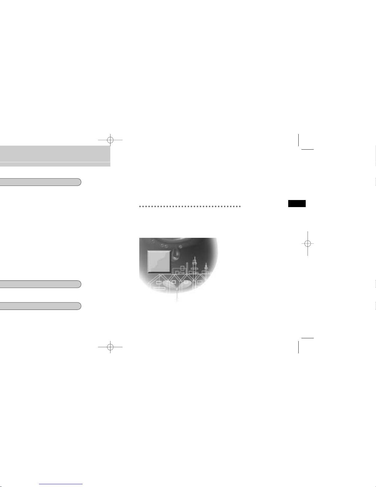
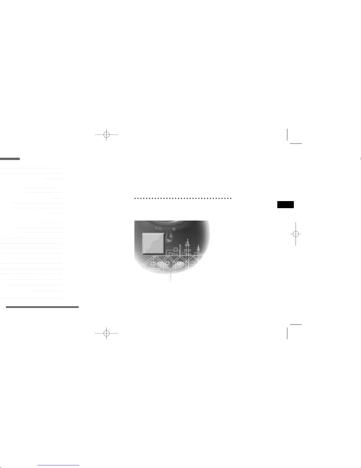
Chapter 1
Overview
This chapter briefly introduces the Camera and
describes its key features, part names and functions.
7
E
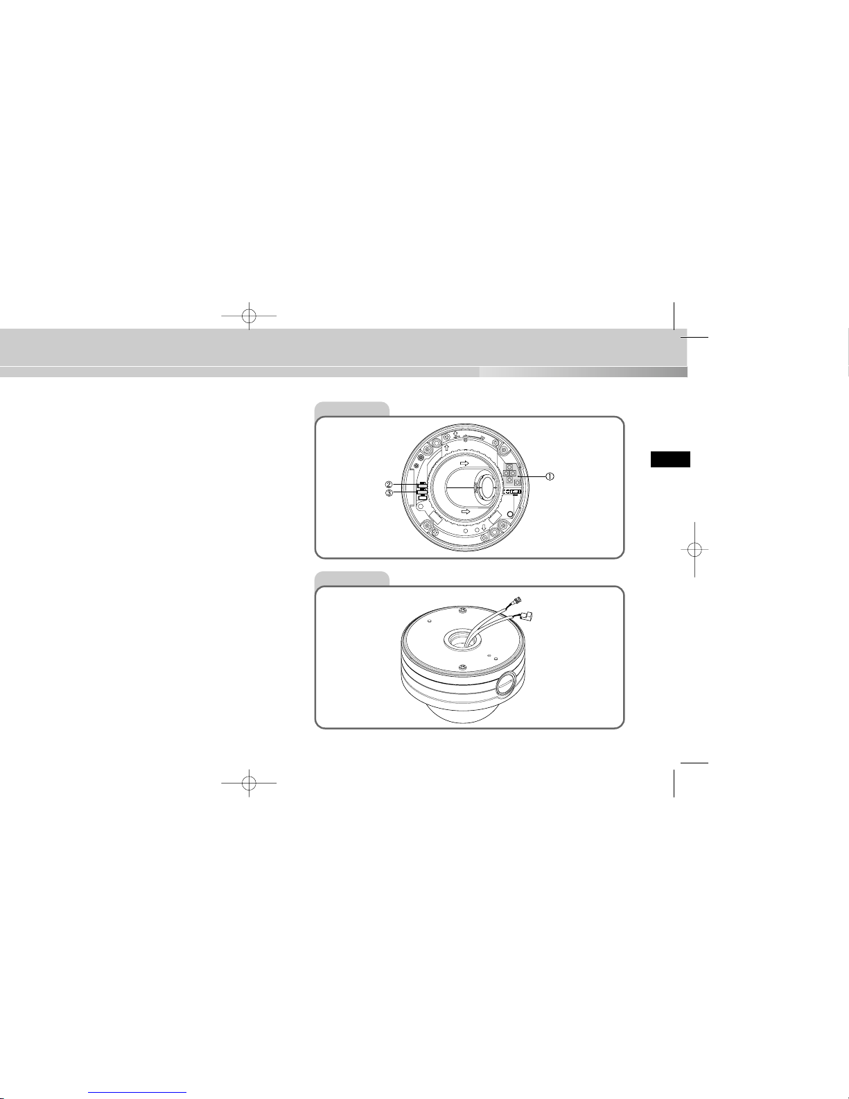
Front View
Rear View
BNC
POWER
9
Chapter 2
Installing the Camera
This chapter explains what to check before installing the
Camera, how to choose an installation site, and what
precautions should be taken during installation.
Now, let’s install the Camera and connect cables.
11
User’s Guide
U
se
r’s
G
u
id
e
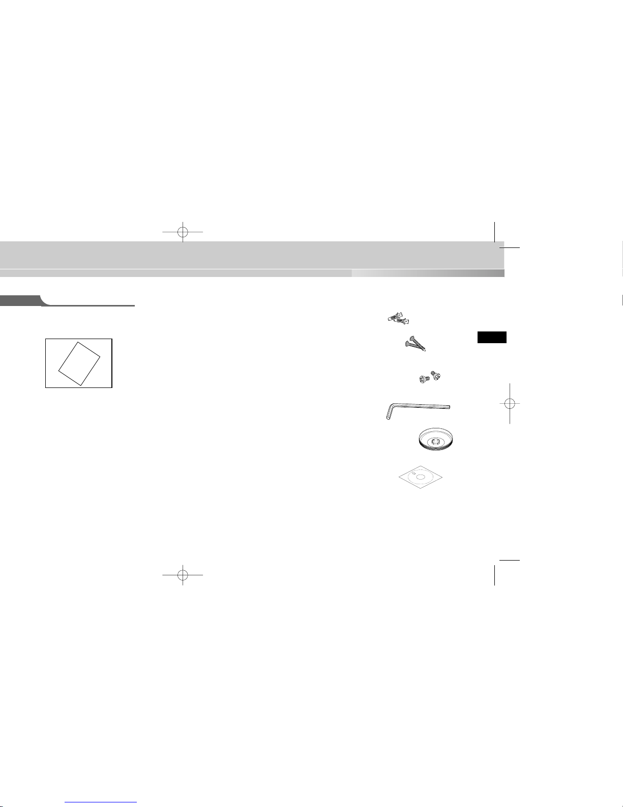
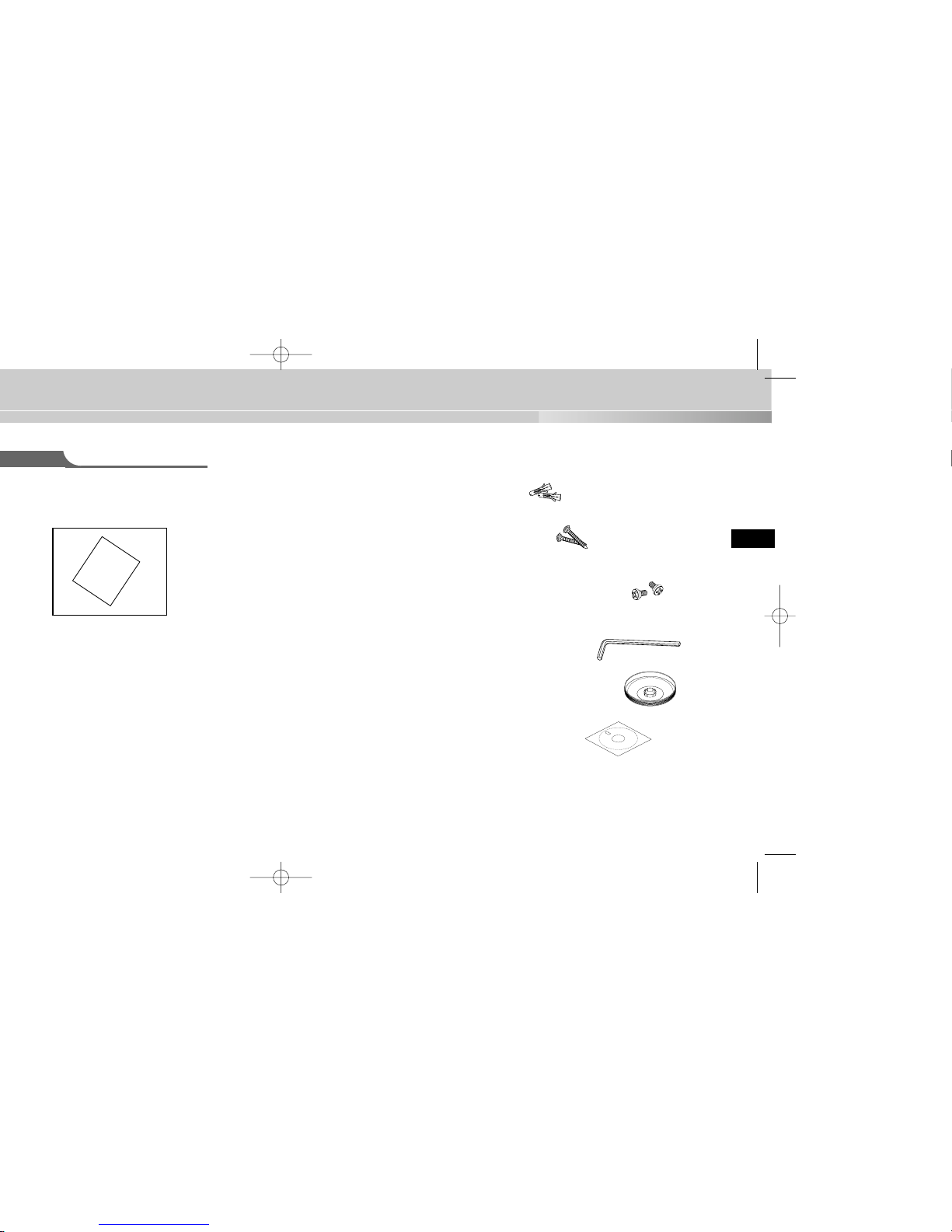
✔ PLASTIC ANCHOR 2 ea. ❙❙for ceiling installation
✔ ASSY SCREW TAPPING 2 ea. ❙❙for ceiling installation
(TH M4 X L30 BLK + 0 RING)
✔ ASSY SCREW MACHINE 2 ea. ❙❙Attach to the holes at the
bottom for waterproof protection when installing the
camera on a pipe (CH M5 L8 XM7 + 0 RING)
✔ L WRENCH 1 ea. ❙❙for COVER DOME removal
✔ DECORATION-MOUNT 1 ea. ❙❙for covering the gap between
the ceiling and the PIPE when fastening using the PIPE
(ABS 94 V0)
✔ TEMPLET 1 ea. ❙❙An installation GUIDE for installing
on a ceiliing (ART PAPER)
13
Installation Examples
✔ It can be directly installed on ceilings.
✔ It can be directly installed on pipes coming down from the ceiling.
✔ It can be directly installed on walls.
✔ It can be directly installed on pipes protruding from the wall.
✔ It can also be installed on corners of the building or on columns by using a
WALL MOUNT ADAPTER (SADT-101WM), CONER MOUNTADAPTER
(SADT-110CM), or POLE MOUNT ADAPTER (SADT-100PM).
(These items are sold separately.)
15
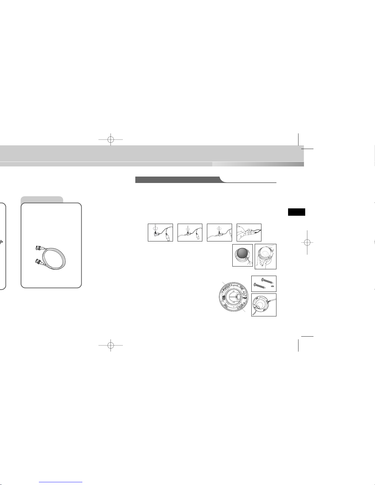
Installing the Camera
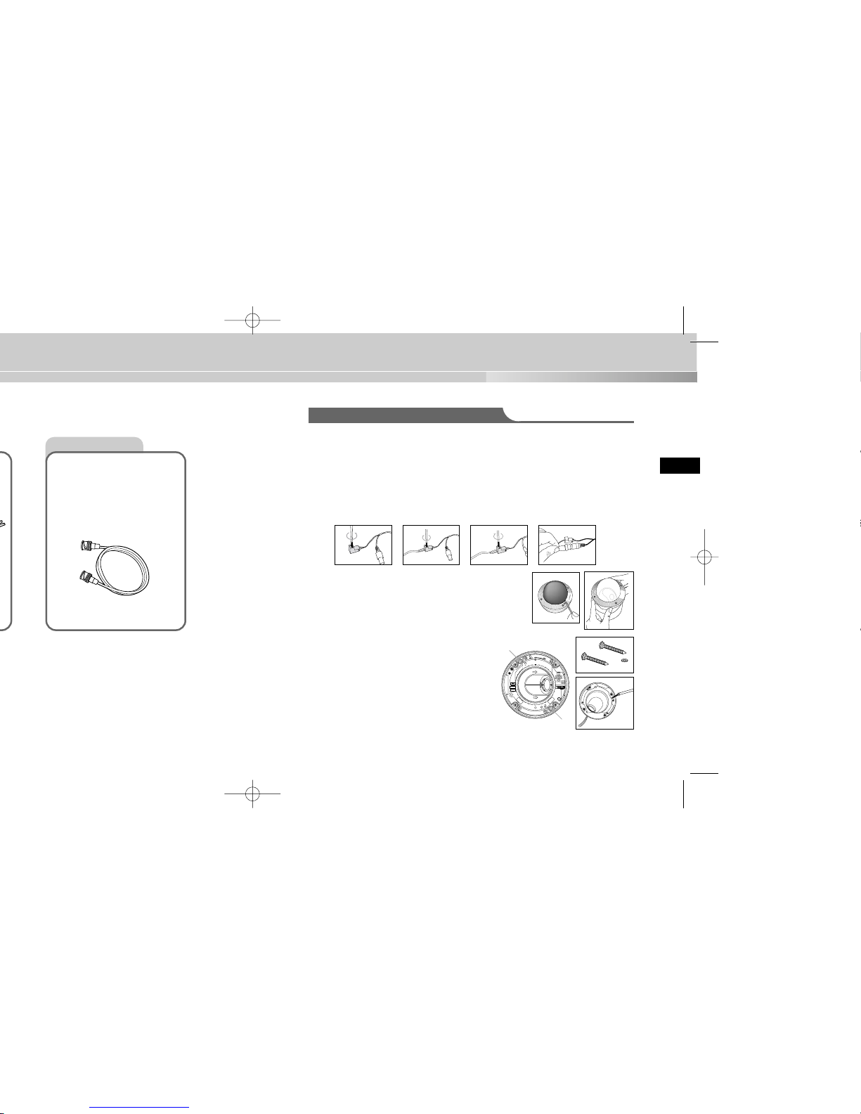
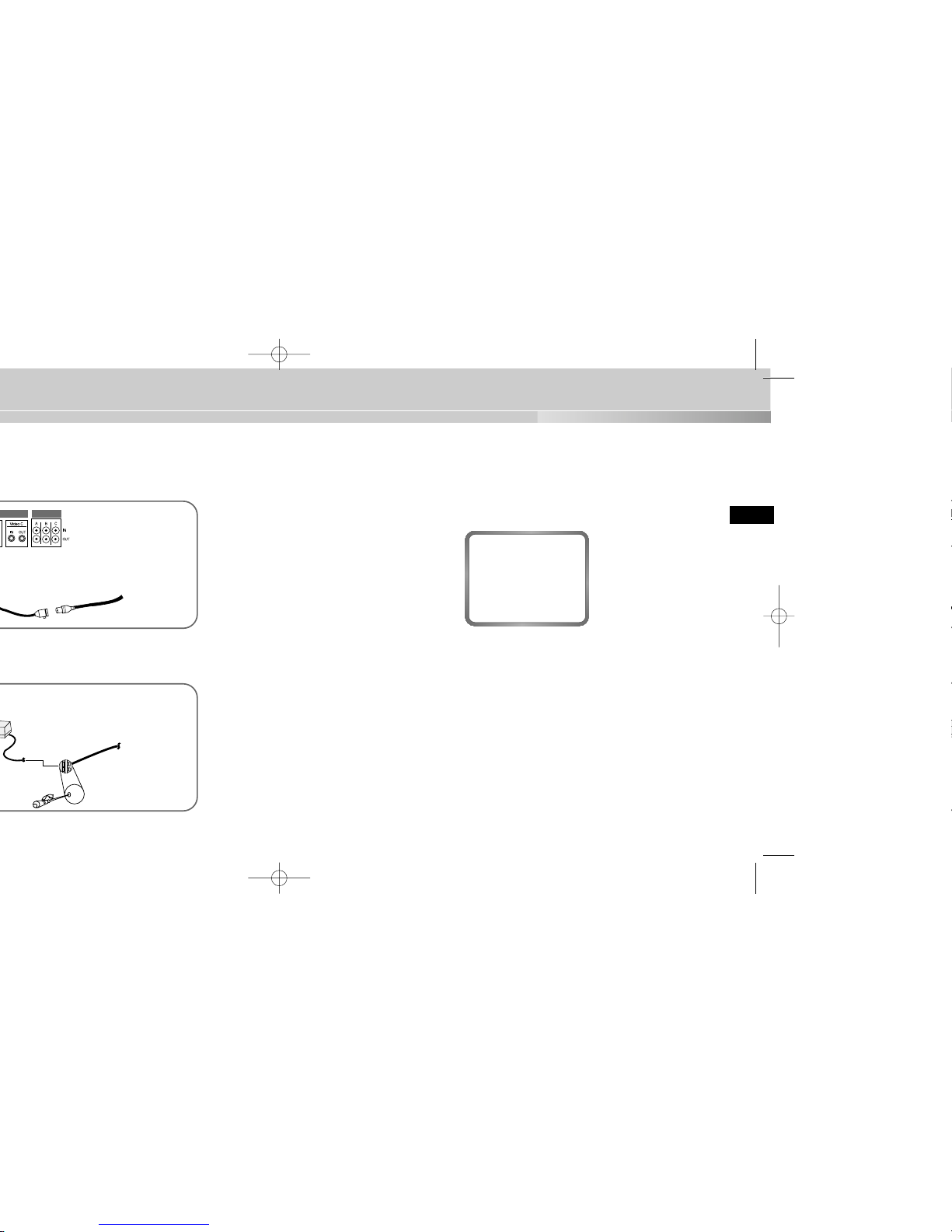
Video Cable
The cable that connects the
video output terminal of the
Camera to the monitor is a
BNC cable.
For installing directly on a ceiling
1. Choose an installation site that can sufficiently support the weight of the equip-
ments to be installed.
2. Attach the supplied template to the installation site, drill pilot holes (5 mm diam
eter, min. 35 mm depth), and then install and secure the supplied plastic
anchors (HUD 5).
3. Connect the power cord and video cable, and arrange them so that they will not
be damaged or caught when installing the CAMERA.
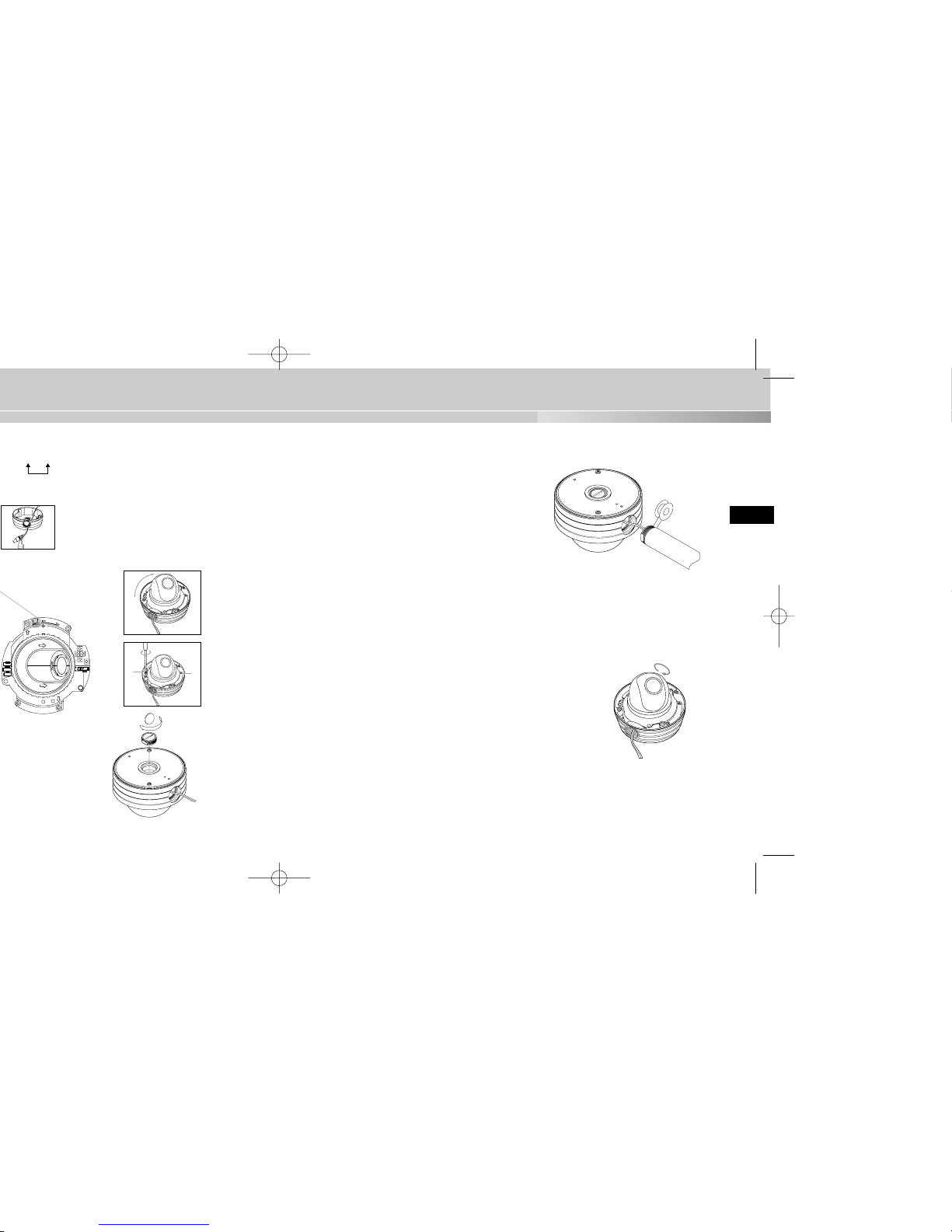
4. Remove the DOME COVER to install the CAMERA.
1) Use the supplied L WRENCH to unfasten the 4
BOLTS for CASE fixing by turning them counterclockwise as shown in the illustration.
2) Disassemble the ASSY-DOME in the direction
shown in the illustration.
5. Install the CAMERA.
Align the CAMERA’s installation holes to the
holes where the PLASTIC ANCHORS are
inserted and then fasten the ASSY SCREWTAPPINGS (TH M4 X 30) with O RINGS.
(2 spots) (It will not be waterproof without O
RINGS.)
SAMSUNG
1) 2)
➜
17
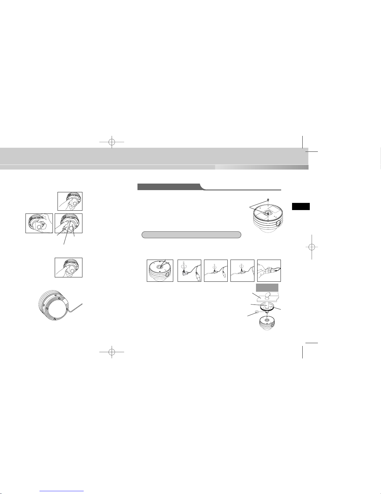
COVERLENS
LENS
BODY
STOPPERRING
For installing on a pipe
1. Choose an installation site that can sufficiently sup
port the weight of the equipments to be installed.
2. Fasten the supplied ASSY SCREW MACHINE
(CH M5 L8 XM7 + 0 RING) in each of the two spots
to prevent water or dust from entering the unit.
3. Fit the DECORATION MOUNT into the PIPE. (A DECORATION MOUNT is used
to conseal the hole in finished ceiling when installing indoor.)
4. Connect the power cable and video cable.
5. After arranging the connected power cable and
video cable inside the PIPE and then pulling them
out, put together the CAMERA’s PIPE assembly
screw (3/4” Threaded) and the PIPE’s screw (3/4”
Threaded) to fasten the SET. (*Wrap a TEFLON
TAPE around the threaded area of the PIPE to make
the connection watertight, and make sure that the
cables are not caught by the fastening area.)
DECORATION
MOUNT
CEILING
BOARD
SCREW
MACHINE
PIPE(3/4”
Threaded)
TEFLON
TAPE
For installing on a pipe coming down from the ceiling
Concrete
Ceiling
19
SAMSUNG
SAMSUNG
1)
2)
3)
4)
2)
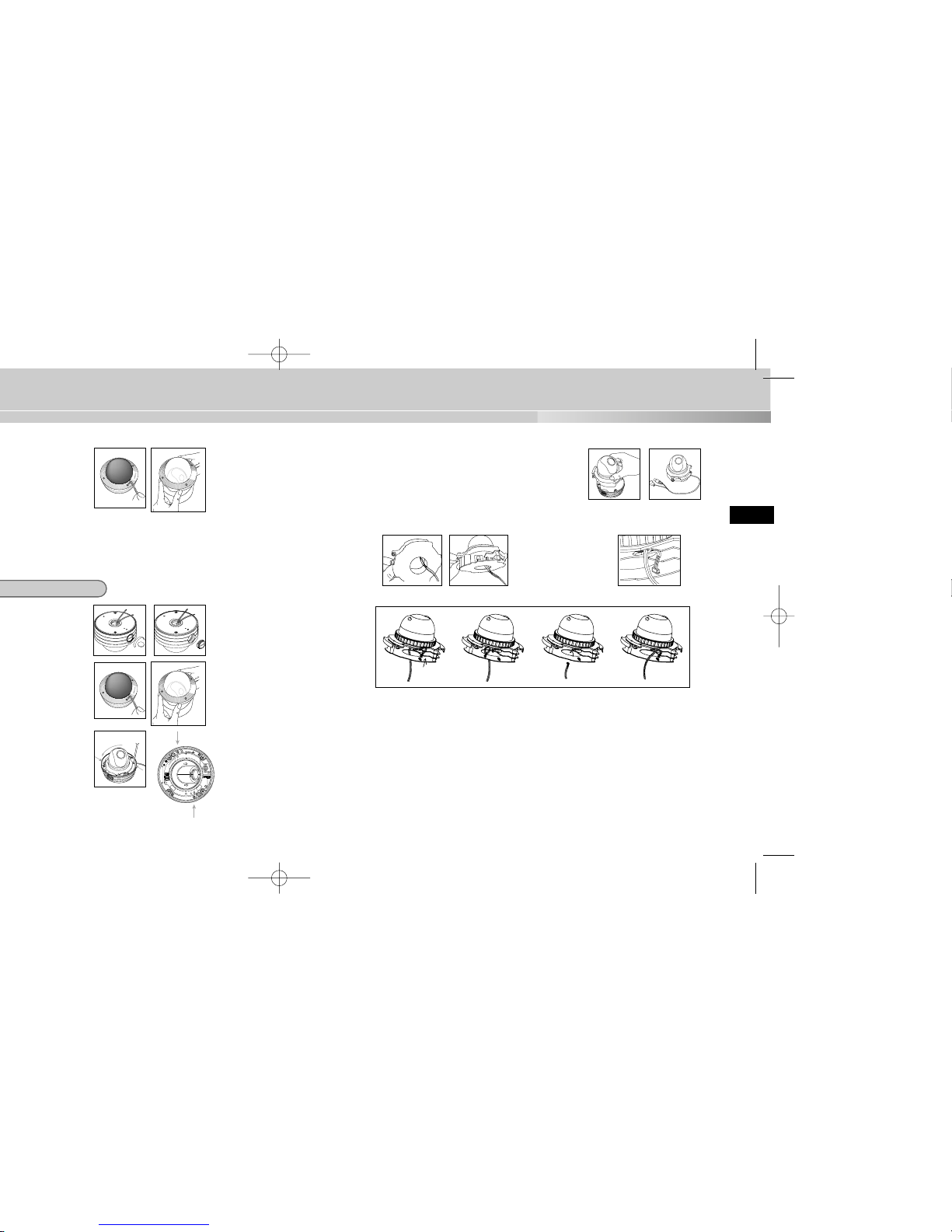
5) Remove the CAMERA body from the CASE.
(Completely separate the power cable from the
video cable.)
6) Disconnect the power and video cables from the
PCB and arrange them so that they can be passed through the PIPE
assembly hole on the side of the CASE as shown in the illustration.
Without passing throught the
center hole of the PCB, fasten the cable to the cable fixing clip from the outside of
the CAMERA, and then join
the CONNECTOR. (If the
cable is not fastened to the
cable fixing clip, any excessive force applied to the cable
will directly affect the CONNECTOR and PCB and
cause damage.)
Disconnect the
CONNECTOR
from the PCB.
Remove the cable
from the cable fixing
clip.
Through the center
hole of the PCB,
remove the cable
from the CAMERA.
➠➠➠
➮
➮
➜
➜
21
9) After arranging the connected power
cable and video cable inside the PIPE
and then pulling them out, put together
the CAMERA’s PIPE assembly screw
(3/4” Threaded) and the PIPE’s screw
(3/4” Threaded) to fasten the SET.
(*Wrap a TEFLON TAPE around the
threaded area of the PIPE to make the
connection watertight, and make sure
that the cables are not caught by the
fastening area.)
10) Adjust the LENS direction and assemble the DOME COVER.
(Refer the steps 6 to 8 of the ceiling installation for LENS adjustment and
DOME COVER assembly.)
➣
How to switch the top and bottom of the screen if
installing the DOME COVER facing up Loosen the
STOPPER-RING, remove the COVER-LENS, and
rotate the LENS body 180 degrees so that the
BOTTOM mark is pointing downward. Put the
COVER-LENS back on, position the LENS in the
direction you want, and then turn the STOPPERRING clockwise to tighten it.
180º
23
E
4. Decide on the type of power source you want to use and then adjust the power
selection switch located at the bottom of the power adapter. Then, plug the
power adapter into the power receptacle.
5. If the camera operates normally, the following screen will be displayed for 5 seconds before it disappears.
6. When controlling an RS485, please check the following:
- Communication Speed: 4800 bps ~ 38400 bps
- Data Bit Number: 8 bits
- Stop Bit Number: 1 bit
- Parity Bit: None
ADDR: 0
TYPE : RS485, HALF
BAUD: 38400
LENS CHECK OK!
25
E
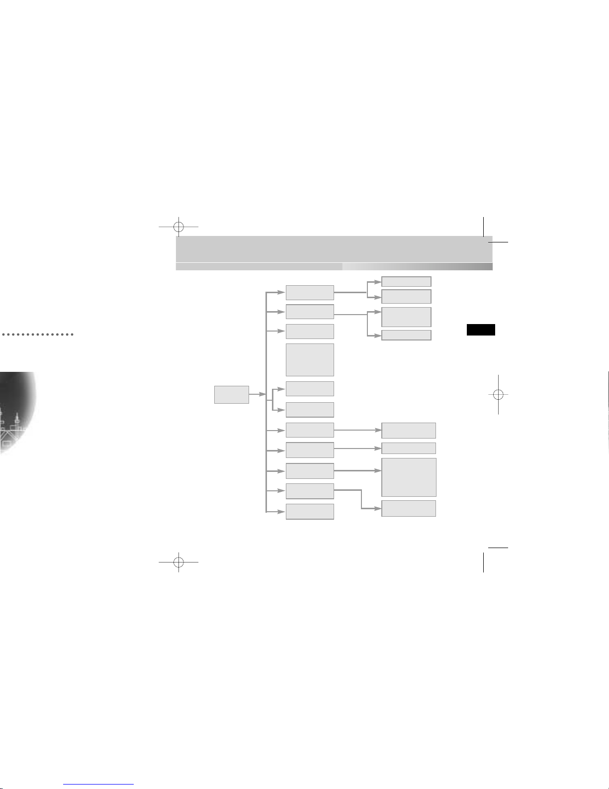
Structure of the Setup Menu
ON...
ALC...
MANU...
MANU...
LINE...
ON...
CAMERA ID
ON.../OFF
CAMERA ID SETUP
CAMERA ID
POSITION SETUP
AREA SETUP
BLC SETUP
LEVEL SETUP
LEVEL SETUP
3200K/5600K/USER
RED, BLUE SETUP
PHASE SETUP
AREA SETUP
SENSITIVITY SETUP
RS485, PRESET
D-ZOOM, PIP,
MIRROR, POSI/NEGA
ZOOM SPEED
DETAILSETUP
LANGUAGE
IRIS
ALC.../MANU...
AUTOFOCUS
AF/ONEAF/MF
AGC
ON/OFF
MOTION
S.SLOW~F.FAST
WHITE BAL
ATW/AWC/MANU...
SYNC
INT/LINE...
SPECIAL
...
ENTER
(2sec)
MOTION DET
ON.../OFF
EXIT
QUIT/SAVE/PRESET
SHUTTER
OFF/1/100~1/10K
OFF/AUTO
X2~X128
OFF/FIX X2~X128
27
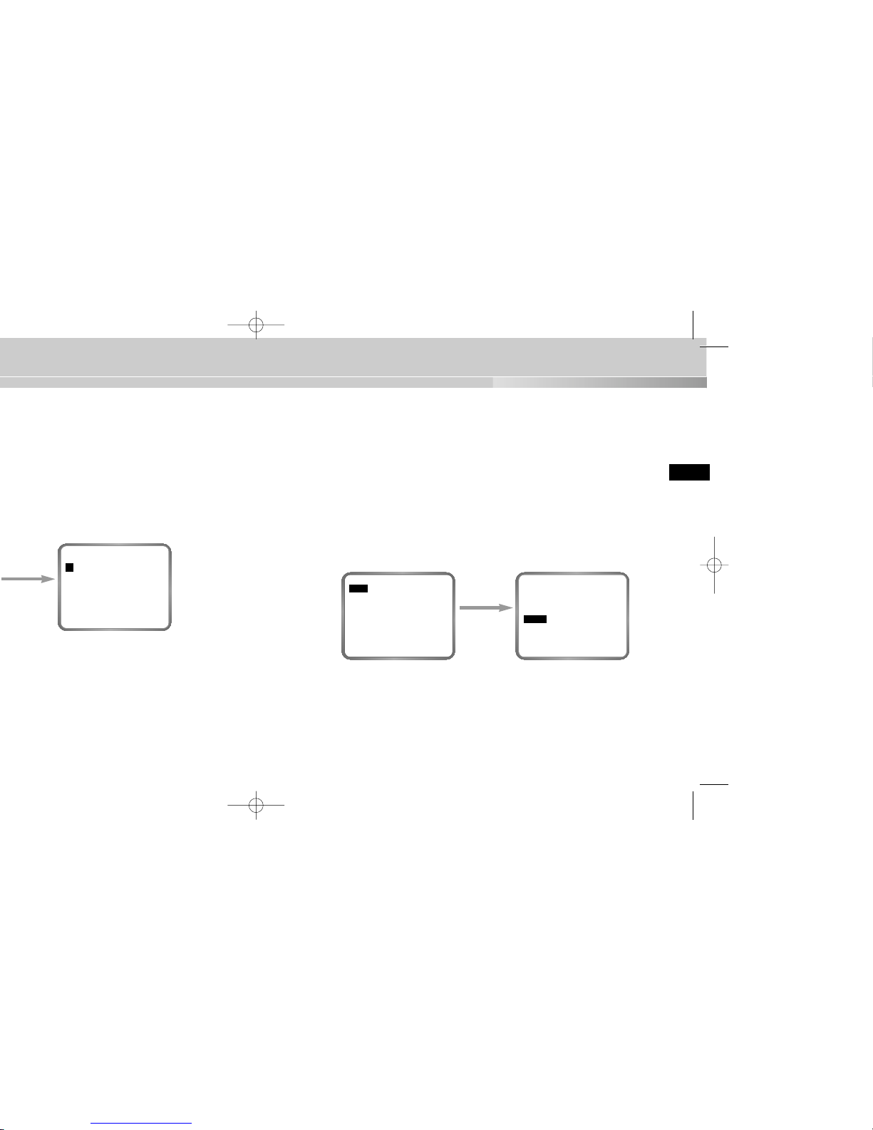
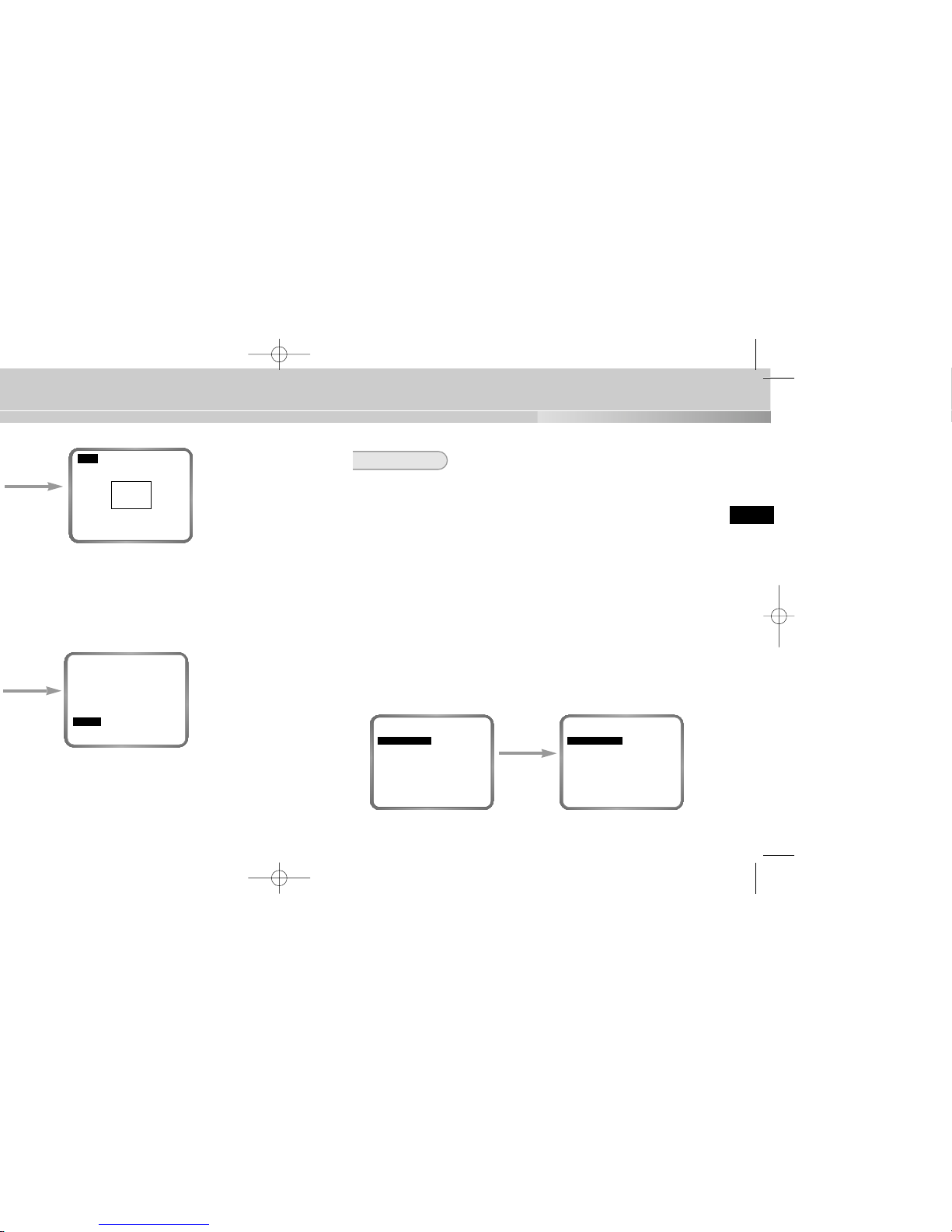
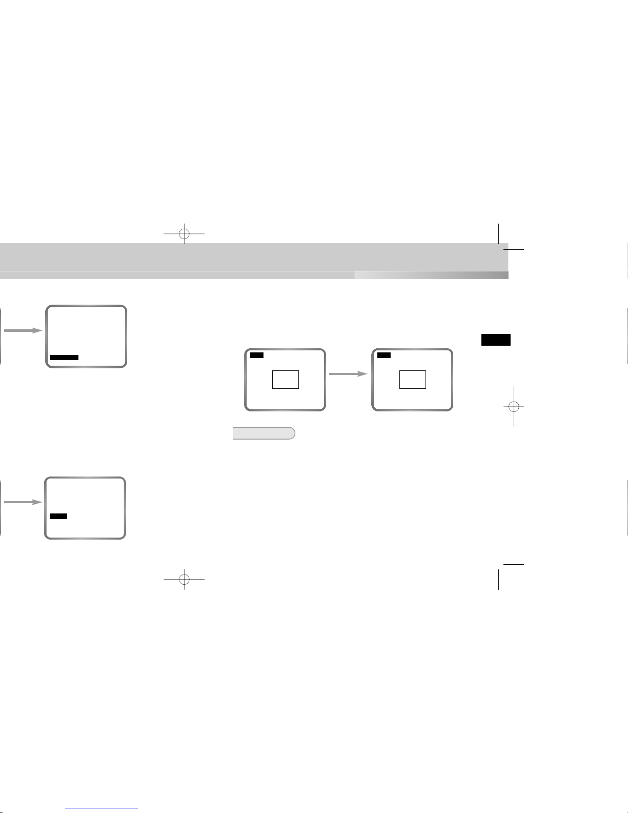
➼ ALC (Auto Light Control)
If you set the IRIS to ALC and press the [ENTER] key, a submenu screen where
you can set the video output level and BLC will be displayed.
In the LEVEL item, you can use the [LEFT/RIGHT] keys to set the video output
level.
If you set the BLC menu to ON, the BLC function will be applied to the screen area
specified in the AREAmenu.
The AREAmenu, where you specify the screen area to which the BLC function will
be applied, can be set to PRESET or USER. If you set the AREAmenu to PRESET, the BLC function will be applied to the area specified at the time of factory
shipment. If you set the AREAmenu to USER and press the [ENTER] key, users
can specify the area to which the BLC function will be applied.
➼ BLC (Back Light Compensation; a submenu of the ALC/MANU... menu)
If you use an ordinary camera when a strong light source, such as a spot light,
is shining from behind the subject, the subject will appear dark on the monitor
because of the back light. In order to solve the problem of back light, the
Camera appropriately sets the BLC, which is a submenu of the ALC/MAN, to
enable you to have a clear video under any light source.
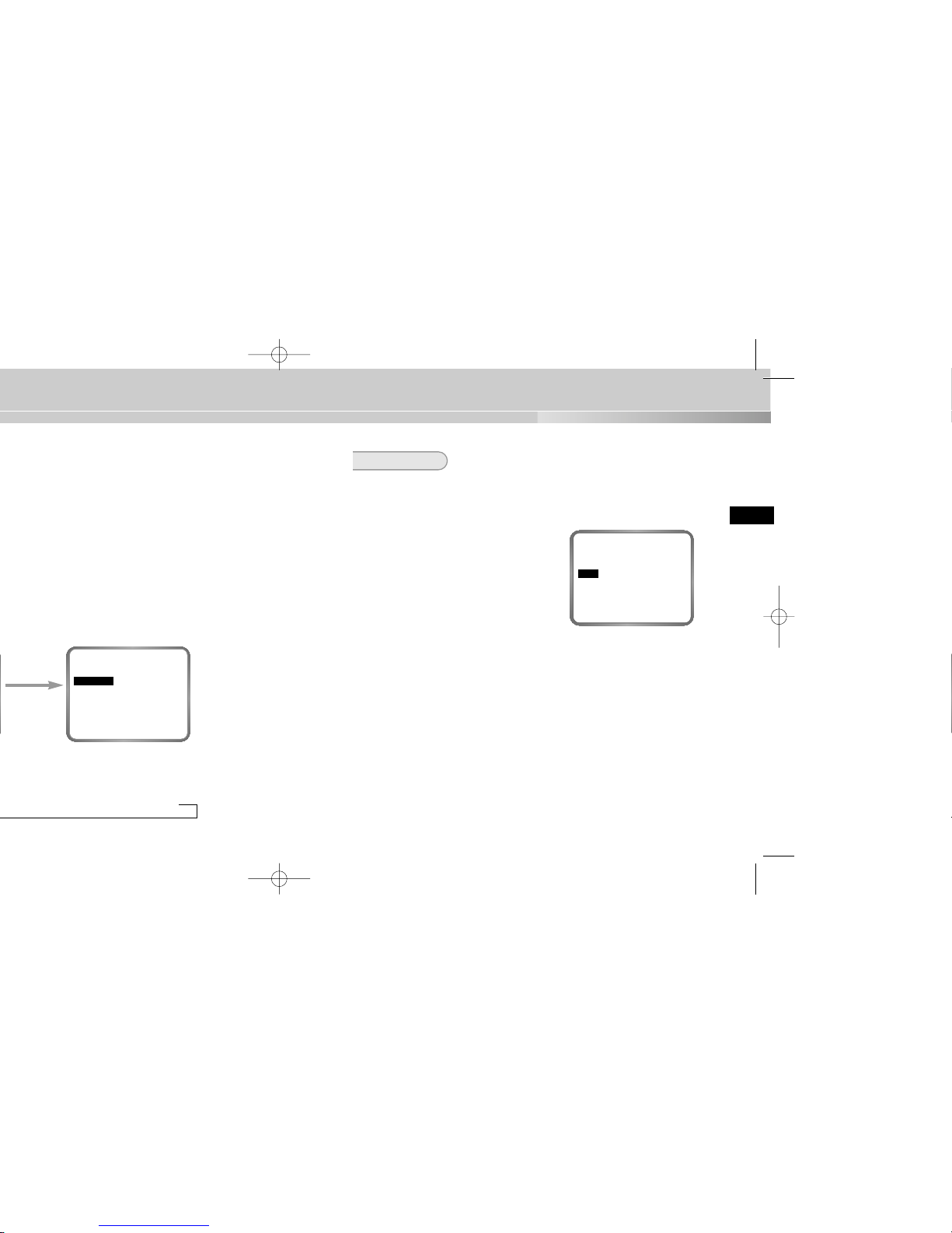
When you press
the [ENTER] key
CAMERA ID OFF...
IRIS ALC...
AUTO FOCUS AF
SHUTTER AUTO X8
MOTION F.FAST
WHITE BAL ATW
SYNC INT
SPECIAL ...
MOTION DET OFF
EXIT QUIT
(ALC)
AREA USER...
BLC OFF
LEVEL(0) ----|---RET
When you press
the [ENTER] key
(CAMERA ID)
A B C D E F G H I J K L
M N O P Q R S T U V W X
Y Z 0 1 2 3 4 5 6 7 8 9
. : ! - + * () /
SP
❿❿➛➛
SP
LOCATION...
RET
..........
29
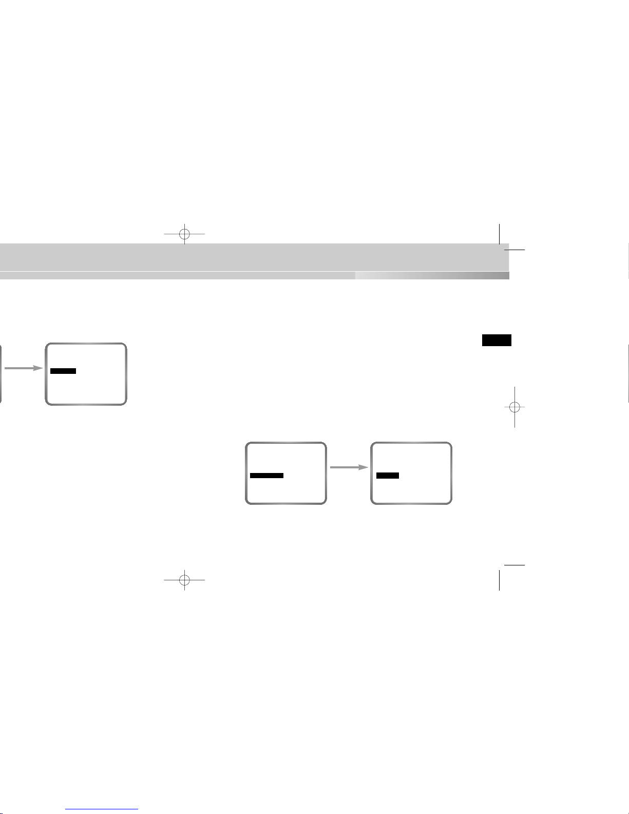
AUTO FOCUS
In the AUTO FOCUS menu, you can specify the Focus method. You can set the
Focus to ONEAF, AF, or MF.
➼ AF (Auto Focus)
Automatically FOCUSes by continuously monitoring the screen with the AUTO
FOCUS MODE. In the AF MODE, a FOCUS key press will not be processed
because Focusing is done automatically when you move the ZOOM key.
➼ ONEAF (One Time Auto Focus)
The ONE-AF Mode focuses only when the Tele key of the ZOOM is pressed.
This is same as the MF Mode while the Camera is stopped and same as the
AF Mode while it is moving.
➼ MF (Manual Focus)
The user can manually adjust the focus with the MANUAL FOCUS MODE.
In the AUTO FOCUS menu, use the LEFT/RIGHT keys to select AF, ONEAF,
or MF.
Using the [LEFT,
RIGHT] keys
CAMERA ID OFF...
IRIS ALC...
AUTO FOCUS AF
SHUTTER AUTO X8
MOTION F.FAST
WHITE BAL ATW
SYNC INT
SPECIAL ...
MOTION DET OFF
EXIT QUIT
CAMERA ID OFF...
IRIS ALC...
AUTO FOCUS ONEAF
SHUTTER AUTO X8
MOTION F.FAST
WHITE BAL ATW
SYNC INT
SPECIAL ...
MOTION DET OFF
EXIT QUIT
Using the [LEFT,
RIGHT, TOP,
BOTTOM] keys
SIZE
POSITION
When you press
the [ENTER] key
(MANUAL)
LEVEL (00) ----|----
RET
31
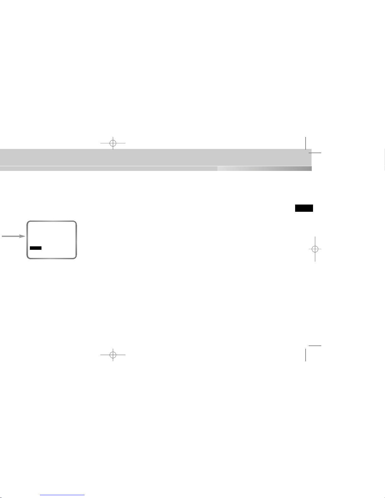
AGC/MOTION
➼ AGC (Auto Gain Control)
You can specify whether to control the AGC GAIN when the obtained video is
below a certain level of brightness because it was recorded under insufficient
lighting.
From the SET UP MENU, use the UP/DOWN
keys while in the high-speed SHUTTER
(1/100 ~ 1/10K) mode or OFF mode to position
to AGC, use the LEFTor RIGHT key to position
to ON, and execute the AGC function.
➼ MOTION
This can be used when in low-speed AUTO, and there are five levels:
S.SLOW, SLOW, NORM, FAST, and F.FAST.
- S.SLOW is used to minimize the AGC GAIN to monitor motionless objects in
dark places.
- SLOW is used to lower the AGC GAIN to monitor objects that do not move
about much in dark places.
- NORM is used to set the AGC GAIN to medium to monitor moving objects in
dark places.
- FAST is used to increase the AGC GAIN to monitor fast moving objects in
dark places.
- F. FAST is used to maximize the AGC GAIN to monitor very fast moving
objects in dark places.
CAMERA ID OFF...
IRIS ALC...
AUTO FOCUS AF
SHUTTER OFF
AGC ON
WHITE BAL ATW
SYNC INT
SPECIAL ...
MOTION DET OFF
EXIT QUIT
Using the [LEFT,
RIGHT] keys
→
1/250 →1/500 →1/1000 →1/2000 →1/4000
AUTOX4 →AUTOX6 →AUTOX8 →AUTOX12
→
AUTOX48 →AUTOX64 →AUTOX96
→
FIXX4 →FIXX6 →FIXX8 →FIXX12
→
FIXX48 →FIXX64 →FIXX96 →FIXX128
CAMERA ID OFF...
IRIS ALC...
AUTO FOCUS AF
SHUTTER AUTO X12
MOTION F.FAST
WHITE BAL ATW
SYNC INT
SPECIAL ...
MOTION DET OFF
EXIT QUIT
33
➼ ATW
Set the WHITE BAL menu to ATW.
➼ AWC
Set the WHITE BAL menu to AWC and press the [ENTER] key with a piece of
white paper placed in front of the lens. In the AWC mode, Auto White Balance
Control works only when the [ENTER] key is pressed.
➼ MANU (Manual White Balance)
If you select the MANU... item and press the [ENTER] key, a MANU... submenu screen where you can select the Manual White Balance will be displayed. You can select 3200°K, 5600°K, or USER mode by pressing the
LEFT/RIGHT keys in the PRESET menu.
When you press
the [ENTER] key
CAMERA ID OFF...
IRIS ALC...
AUTO FOCUS AF
SHUTTER AUTO X8
MOTION F.FAST
WHITE BAL MANU...
SYNC INT
SPECIAL ...
MOTION DET OFF
EXIT QUIT
(AWB/MANU)
PRESET OFF(USER)..
RED (0) ----|---BLUE (0) ----|---RET
Using the [LEFT,
RIGHT] keys
CAMERA ID OFF...
IRIS ALC...
AUTO FOCUS AF
SHUTTER AUTO X8
MOTION FAST
WHITE BAL ATW
SYNC INT
SPECIAL ...
MOTION DET OFF
EXIT QUIT
35
➼ CTRL TYPE
This function is not used on the Anti-Vandal Dome Camera.
➼ RS485
Select the Baud Rate (4800, 9600, 19200, or 38400 bps) and Camera Address
(0~255) for RS485 communication. When using a multiple number of cameras,
each must use a different address. (If the same address is used, communication may not be possible.)
➼ PRESET
You can select and store the desired ZOOM and FOCUS positions from 0 to 9.
➼ D-ZOOM
Sets the magnification of the Digital Zoom. Magnification can be set between
2x and 10x in 5 step increments.
➼ PIP
Picture In Picture function. Shows a 1/16 screen only when operating the
Digital Zoom. If the D-ZOOM is OFF, a ‘disbled’ symbol (—) will be displayed.
➼ MIRROR
Horizontally flips the video output signal.
➼ POSI/NEGA
Outputs the video output signal normally or inversely.
➼ ZOOM SPEED
Sets the Zoom speed. Pressing the [LEFT, RIGHT] keys in the ZOOM SPEED
menu will change the zoom speed as follows:
1 : Takes about 14 seconds from 1x to x12 Slowest speed
2 : Takes about 6 seconds from 1x to x12 Slow speed
3 : Takes about 4 seconds from 1x to x12 Fast speed
4 : Takes about 2 seconds from 1x to x12 Fastest speed
➼ DETAIL
Adjusts the horizontal and vertical sharpness.
If you select ON and press the [ENTER] key, a “SPECIAL” submenu screen where
you can set special functions will be displayed.
When you press
the [ENTER] key
(LINE LOCK)
PHASE (000) ----|----
RET

37
You can store up to 10 Zoom and Focus positions with the PRESET. The PRESET
function can be used when you connect the SSC-1000(Controller[Sold Separately])
and RS485.
When you select the ON... item and press the [ENTER] key, you can use the
[LEFT, RIGHT, UP, DOWN] keys to set the PIP position.
When you select a PRESET number and press the [ENTER] key, you will see a
screen that looks as above.
➼ POSITION SET
Stores the Zoom and Focus positions.
➼ PRESET ID
Sets the ID for the Preset position, as it was the case with the Camera ID.
When you press
the [ENTER] key
PRESET NO. 0
POSITION SET ...
PRESET ID ON...
EXIT QUIT
(PRESET MAP)
0 *1 2 34
56789
RET
ID:PRESET 0
When you press
the [ENTER] key
CTRL TYPE --RS485 ...
PRESET ...
D-ZOOM X2
PIP ON...
MIRROR OFF
POSI/NEGA +
ZOOM SPEED 3
DETAIL(0) ----|-LANGUAGE ENGLISH
RET
PIP
SCREEN
When you press
the [ENTER] key
CTRL TYPE ---
RS485 ...
PRESET ...
D-ZOOM OFF
PIP --MIRROR OFF
POSI/NEGA +
ZOOM SPEED 3
DETAIL(0) ----|-LANGUAGE ENGLISH
RET
When you press
the [ENTER] key
(RS485)
BAUD RATE 38400
RS485 ADDR 0
RET
When you press
the [ENTER] key
(PRESET MAP)
0 *1 2 34
5 6 789
RET
ID:PRESET 0
39
You can move the cursor to the SENSITIVITYposition and use the [LEFT/RIGHT]
keys to set the sensitivity for MOTION detection (LOW, MEDIUM, HIGH).
After setting the position in the same way you did with BLC AREA, press the
[ENTER] key to return to the previous MOTION DET MENU.
Using the [LEFT,
RIGHT, TOP,
BOTTOM] keys
SIZE
POSITION
SIZE
POSITION
EXIT
Exits the setup menu and returns to the usual operation mode.
➼ QUIT
Ignores any changes you have made and restores the previously saved setup
menu.
➼ SAVE
Saves the settings that have been changed so far.
➼ PRESET
Saves the settings that have been changed so far.
When you press
the [ENTER] key
(MOTION DET)
AREA PRESET...
SENSITIVITY MEDIUM
RET
Using the [LEFT,
RIGHT] keys
CTRL TYPE --RS485 ...
PRESET ...
D-ZOOM X2
BIB EIN...
SPIEGEL AUS
POSI/NEGA +
ZOOM GESCHW 3
DETAIL(0) ----|--
SPRACHE DEUTSCH
RUE
41
E
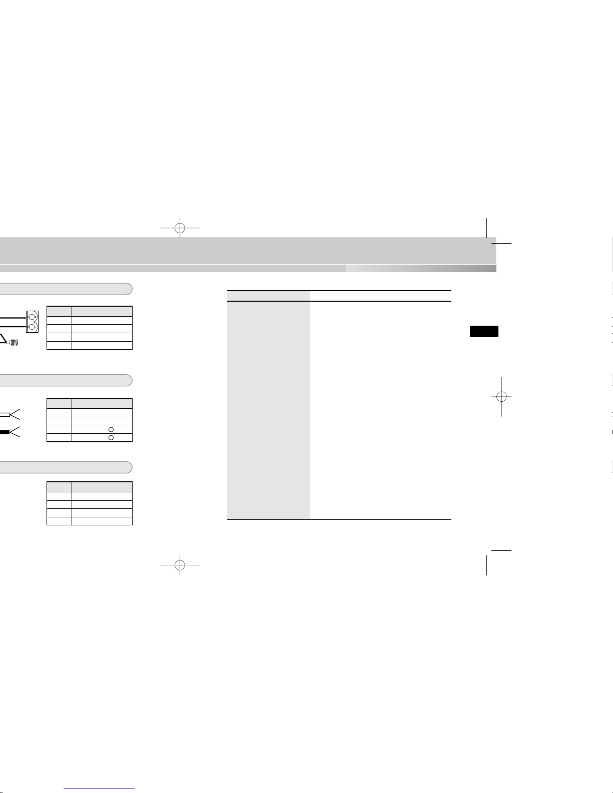
Product Specifications
ITEM DESCRIPTION
Product Type Anti-Vandal Dome Camera
Power Source Voltage AC 24V ± 10% (NTSC:60Hz ± 0.1Hz, PAL:50Hz ± 0.1Hz),
DC12V +10% ~ -5%
Power Consumption Approx. 6W
Broadcast System NTSC(PAL) Standard Color System
Imaging Device 1/4 inch IT S-HAD CCD
Effective Pixel NTSC : 768(H) X 494(V)
PAL: 752(H) X 582(V)
Scanning Method NTSC : 525 Line, 2:1 Interlace
PAL: 625 Line, 2:1 Interlace
Line Frequency Horizontal(NTSC) :15,734 Hz(INT) / 15,750 Hz(L/L)
Horizontal(PAL) :15,625 Hz(INT) / 15,625 Hz(L/L)
Vertical(NTSC) : 59.94 Hz(int) / 60 Hz(L/L)
Vertical(PAL) : 50 Hz(int) / 50 Hz(L/L)
Synchronization Method INT/Line Lock
Resolution 480 TV Lines
S/N Ratio 52dB (AGC Off)
Minimum Scene Illumination 1 Lux (30 IRE, Sense Up Off)
0.01 Lux (30 IRE, Sense Up x128)
Color Temperature ATW/AWC/Manual MODE
(3200°K, 5600°K, R/B Gain Control)
Electronic Shutter Off, 1/100(NTSC), 1/120(PAL), 1/250, 1/500, 1/1K,
1/2K, 1/4K, 1/10K sec
Pin No Pin Specifications
1 Camera Power Input
2 Camera Power Input
3 GND
4 Video Signal Output
White
Green
Green
Red
Pin No Pin Specifications
1 ALARM(Open/Gnd)
2 GND
3 RS485 4 RS485 +
Pin No Pin Specifications
1 GND
2 RS232-RXD(CAM)
3 RS232-TXD(CAM)
4 +5V


3
9. Sollte das Gerät nicht störungfrei funktionieren, setzen Sie sich mit Ihrem Händler
oder dem nächsten Kundendienstzentrum in Verbindung. Das Gerät darf niemals in
keiner Weise zerlegt oder modifiziert werden. (Samsung übernimmt keine Haftung
für Probleme, die durch unbefugte Abänderungen oder einen Reparaturversuch herbeigeführt sind.)
10. Beim Reinigen darf Wasser niemals direkt auf die Geräteteile gelangen. (Andernfalls
besteht die Gefahr eines Brandes oder Stromschlags.) Die Oberfläche kann mit
einem trockenen Tuch abgewischt werden. Verwenden Sie für das Gerät keine
Reinigungsmittel oder chemischen Reiniger, da sich durch solche Mittel die Farbe
ablösen und der Oberflächenüberzug beschädigt werden kann.
Achtung
Die Nichtbeachtung eines mit Achtung gekennzeichneten Hinweises kann
zu Verletzungen und Sachschaden führen.
1. Lassen Sie keine Gegenstände auf das Gerät fallen, und setzen Sie es keinen starken
Stößen aus. Setzen Sie die Kamera keinen starken Vibrationen oder magnetischen
Störfeldern aus.
2. Die Kamera darf nicht an Orten mit hohen Temperaturen (über 50 ºC) bzw. tiefen
Temperaturen (unter -10 ºC) oder hoher Luftfeuchtigkeit installiert werden.
(Andernfalls besteht die Gefahr eines Brandes oder Stromschlags.)
3. Installieren Sie das Gerät nicht in der Nähe von Wärmequellen, wie z. B. einem
Heizgerät oder Heizkörper, und an Orten, an denen es direktem Sonnenlicht ausgesetzt ist. (Hier besteht Feuergefahr.)
4. Wenn Sie die bereits installierte Kamera an einen anderen Ort verlegen wollen, achten Sie darauf, die Kamera auszuschalten, bevor Sie sie abnehmen oder neu installieren.
5. Die Installation sollte an einer gut belüfteten Stelle erfolgen.
6. Ziehen Sie bei einem Gewitter den Netzstecker. (Die Nichtbeachtung kann zu Feuer
oder einer Beschädigung des Geräts führen.)
5
D
Kapitel 1
Übersicht
Dieses Kapitel enthält eine kurze Einführung in die Kamera
und beschreibt ihre Hauptmerkmale, die Bezeichnung der
Teile und ihre Funktionen.

7
D
Bezeichnung der Teile und ihre Funktionen
Vorderseite
Rückseite
BNC
POWER
9
Kapitel 2
Installation der Kamera
In diesem Kapitel wird erläutert, was vor der Installation der
Kamera zu beachten ist, wie man eine geeignete
Installationsstelle auswählt und welche Vorsichtsmaßnahmen bei
der Installation zu treffen sind. Nun können Sie die Kamera
installieren und die Kabel anschließen.
11
Bedienungsanleitung
B
e
d
ie
n
u
n
g
s
a
n
le
itu
n
g
✔ PLASTIKDÜBEL
2 Stck. ❙❙zur Deckeninstallation
✔ SCHNELLMONTAGESCHRAUBEN
2 Stck. ❙❙zur Deckeninstallation
(TH M4 X L30 BLK + 0-RING)
✔ BEFESTIGUNGSSCHRAUBEN
2 Stck. ❙❙Werden bei der Kameramontage an einem Rohr
(CH M5 L8 XM7 + 0-RING) in die Löcher an der Unterseite
eingeschraubt, um das Gerät gegen das Eindringen von
Wasser zu schützen.
✔ L-SCHRAUBENSCHLÜSSEL
1 Stck. ❙❙zur Abnahme der ABDECKUNGSHAUBE
✔ DECORHALTERUNG
1 Stck. ❙❙zur Abdeckung der Lücke zwischen Decke und
ROHR bei Rohrmontage (ABS 94 V0)
✔ SCHABLONE
1 Stck. ❙❙als HILFE bei einer Deckeninstallation
(KUNSTDRUCKPAPIER)

13
Installationsbeispiele
✔ Die Kamera kann direkt an der Decke installiert werden.
✔ Sie kann direkt an einem Rohr, das aus der Decke kommt, installiert werden.
✔ Sie kann direkt an der Wand installiert werden.
✔ Sie kann direkt an einem Rohr, das aus der Wand kommt, installiert werden.
✔ Unter Verwendung einer WANDHALTERUNG (SADT-101WM),
ECKHALTERUNG (SADT-110CM) oder MASTENHALTERUNG (SADT-100PM)
lässt sie sich auch an Gebäudeecken oder Masten installieren. (Diese Artikel
sind separat erhältlich.)
15
Installation der Kamera
Videokabel
Das Kabel, das den
Videoausgang der Kamera mit
dem Monitor verbindet, ist ein
BNC-Kabel.
Direkte Installation an einer Decke
1. Wählen Sie eine Installationsstelle, die das Gewicht des zu installierenden
Geräts tragen kann.
2. Legen Sie die mitgelieferte Schablone an der Installationsstelle an, bohren Sie
Führungslöcher (5 mm Durchmesser, min. 35 mm tief) und befestigen Sie die
mitgelieferten Plastikdübel (HUD 5).
3. Schließen Sie Netzkabel und Videokabel an, wobei Sie sie so anordnen sollten, dass
sie bei der Montage der KAMERA nicht beschädigt oder eingeklemmt werden.
4. Nehmen Sie die HAUBENABDECKUNG ab, um die
KAMERA anzubringen.
1) Lösen Sie mit dem mitgelieferten L-SCHRAUBENSCHLÜSSEL die 4 GEHÄUSEBEFESTIGUNGSSCHRAUBEN, indem Sie sie entgegen dem
Uhrzeigersinn drehen, wie in der Abbildung gezeigt.
2) Nehmen Sie die HAUBE in der in der
Abbildung gezeigten Richtung ab.
5. Montieren Sie die KAMERA.
Bringen Sie die Montagelöcher der KAMERA
mit den Löchern, in denen sich die
PLASTIKDÜBEL befinden, in
Übereinstimmung, und ziehen Sie die
SCHNELLMONTAGESCHRAUBEN mit den
O-RINGEN fest. (2 Punkte)
(Diese sind ohne die O-RINGE nicht wasserdicht.)
SAMSUNG
1) 2)
➜
 Loading...