

Samsung SCC-931T, SCC-931P User Manual
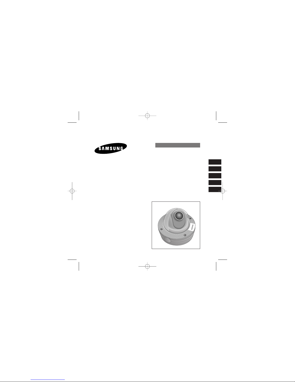
ANTI-V ANDALDOME CAMERA
SCC-931T(P)
User’s Manual
Bedienungsanleitung
Guide de l’utilisateur
Guía del Usuario
Manuale d’uso
E
D
F
Es
I
00355A(01) SCC-931T(P)-eng 2006.1.10 1:49 PM Page 1
2
3
E E
Important Safety Instructions
1. Read these instructions.
2. Keep these instructions.
3. Heed all warnings.
4. Follow all instructions.
5. Do not use this apparatus near water.
6. Clean only with dry cloth.
7. Do not block any ventilation openings. Install in accordance with the
manufacturer’s instructions.
8. Do not install near any heat sources such as radiators, heat registers, or other
apparatus (including amplifiers) that produce heat.
9. Do not defeat the safety purpose of the polarized or grounding-type plug. A
polarized plug has two blades with one wider than the other. A grounding type
plug has two blades and a third grounding prong. The wide blade or the third
prong are provided for your safety. If the provided plug does not fit into your
outlet, consult an electrician for replacement of the obsolete outlet.
10. Protect the power cord from being from being walked on or pinched particularly
at plugs, convenience receptacles, and the point where they exit from the
apparatus.
11. Only use attachments/accessories specified by the manufacturer.
12. Use only with cart, stand, tripod, bracket, or table specified by the manufacturer,
or sold with the apparatus. When a used, caution when moving the
cart/apparatus combination to avoid injury from tip-over.
13. Unplug this apparatus. When a cart is used, use caution when moving the
cart/apparatus combination to avoid injury from tip-over.
14. Refer all servicing to qualified service personnel. Servicing is required when the
apparatus has been damaged in any way, such as power-supply cord or plug is
damaged, liquid has been spilled or objects have fallen into the apparatus, the
apparatus has been exposed to rain or moisture, does not operate normally, or
been dropped.
CAUTION: TO REDUCE THE RISK OF
ELECTRIC SHOCK, DO NOT
REMOVE REAR COVER. NO
USER SERVICEABLE PARTS
INSIDE. REFER TO QUALIFIED
SERVICE PERSONNEL.
To prevent damage which may result in fire or electric shock hazard, do not expose this
appliance to rain or moisture.
This device complies with part 15 of the FCC Rules. Operation is subject to the
following two conditions.
1) This device may not cause harmful interference, and
2) This device must accept any interference that may cause undesired operation.
CAUTION:
Danger of explosion if battery is incorrectly replaced.
Replace only with the same or equivalent type recommended by the manufacturer.
Dispose of used batteries according to the manufacturer’s instructions.
This symbol indicates high voltage
is present inside. It is dangerous
to make any kind of contact with
any inside part of this product.
This symbol alerts you that
important literature concerning
operation and maintenance has
been included with this product.
CAUTION
RISK OF ELECTRIC
SHOCK DO NOT OPEN
00355A(01) SCC-931T(P)-eng 2006.1.10 1:49 PM Page 2
E
5
E
4
Table of Contents
Chapter 1
Overview
This chapter briefly introduces the Camera and
describes its key features, part names and functions.
Chapter 1 Overview 5
Introduction 6
Part Names and Functions 7
Chapter 2 Installing the Camera 9
Checking the Contents of the Package 10
Precautions for Installation and Use 12
Preparing Cables 14
Installing the Camera 15
Connecting Cables and Checking Operations 22
Chapter 3 Setup Menu Overview 24
Structure of the Setup Menu 25
CAMERA MENU Organization 26
CAMERA ID 26
IRIS 26
AUTO FOCUS 29
SHUTTER 30
AGC/MOTION 31
WHITE BAL 32
SYNC 34
SPECIAL 34
MOTION DET 38
EXIT 39
External Connector Pin Specifications 40
Product Specifications 41
00355A(01) SCC-931T(P)-eng 2006.1.10 1:49 PM Page 4
E
7
E
6
Introduction Part Names and Functions
The Anti-Vandal Dome Camera is a dome-typed surveillance device that
offers the best features of surveillance for banks, retail stores, commercial
buildings, industrial settings, and etc. It is designed to withstand intentional
or accidental impact or vandalism, and is waterproof, dustproof, and
shockproof.
The Camera is an advanced surveillance device that enables a maximum
of 120x zoom surveillance with its 12x zoom lens and digital zoom IC.
The Camera is a multifunction surveillance device that is equipped with all
of the key features of the existing surveillance cameras: the Low-Light
Surveillance function that enables shooting moving objects under extremely low illumination, the White Balance function that provides accurate color
rendition under any light source, the BLC function that enables effective
back light compensation even at locations with bright incident light, and the
Auto Focus function that automatically tracks and focuses on the moving
subject.
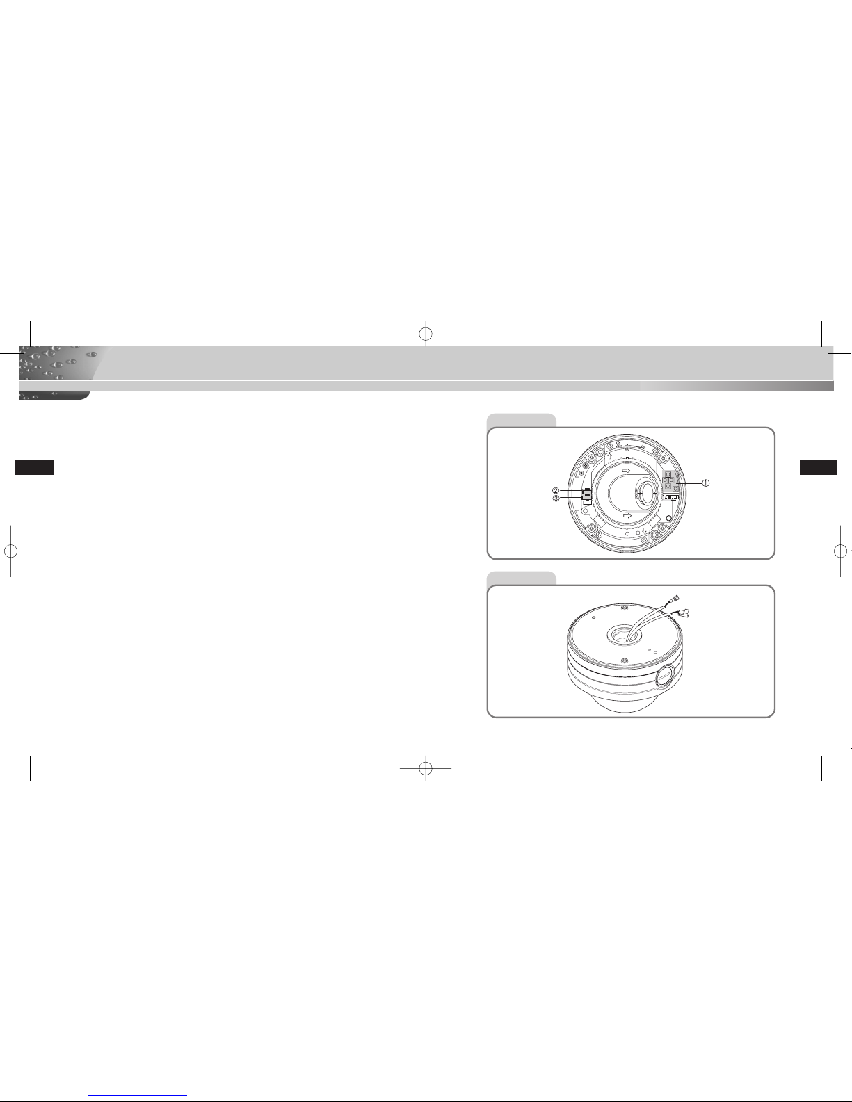
Front View
Rear View
BNC
POWER
00355A(01) SCC-931T(P)-eng 2006.1.10 1:49 PM Page 6
8
9
Part Names and Functions
E E
❶
Camera Operation Switches (Setup Switches)
The functions of the camera operation switches change depending on whether
the Camera is currently in the usual operation mode (i.e., the setup menu is not
showing on the screen) or the setup menu mode.
➻ In the usual operation mode
- [UP/DOWN] Directional keys: The [UP] key is used as the ZOOM TELE
switch, and the [DOWN] key is used as the ZOOM WIDE switch.
- [LEFT/RIGHT] Directional keys: The [LEFT] key is used as the FOCUS NEAR
switch, and the [RIGHT] key used as the FOCUS FAR switch.
- [ENTER] key: This key is used to go into the setup menu.
➻ In the setup menu mode
- [UP/DOWN] Directional keys: These keys are used to move the cursor up and
down.
- [LEFT/RIGHT] Directional keys: These keys are used to move the cursor left
and right, or to sequentially view the values that can be assigned in each
setup menu.
- [ENTER] key: This key is used to select a setup menu with a submenu in
order to open the submenu, and to accept the current value.
These connectors are used to connect the power adapter cable and video input
cable.
These connectors are used to connect an RS485 remote control cable and a
cable used for transmitting the ALARM signal at the time of the MOTION DET
mode.
❷
Power Input Connector and Video Output Connector (4-Pin)
❸
RS485 Connector and Alarm Output Connector (4-Pin)
Chapter 2
Installing the Camera
This chapter explains what to check before installing the
Camera, how to choose an installation site, and what
precautions should be taken during installation.
Now, let’s install the Camera and connect cables.
00355A(01) SCC-931T(P)-eng 2006.1.10 1:49 PM Page 8
10
11
Before Installation
E E
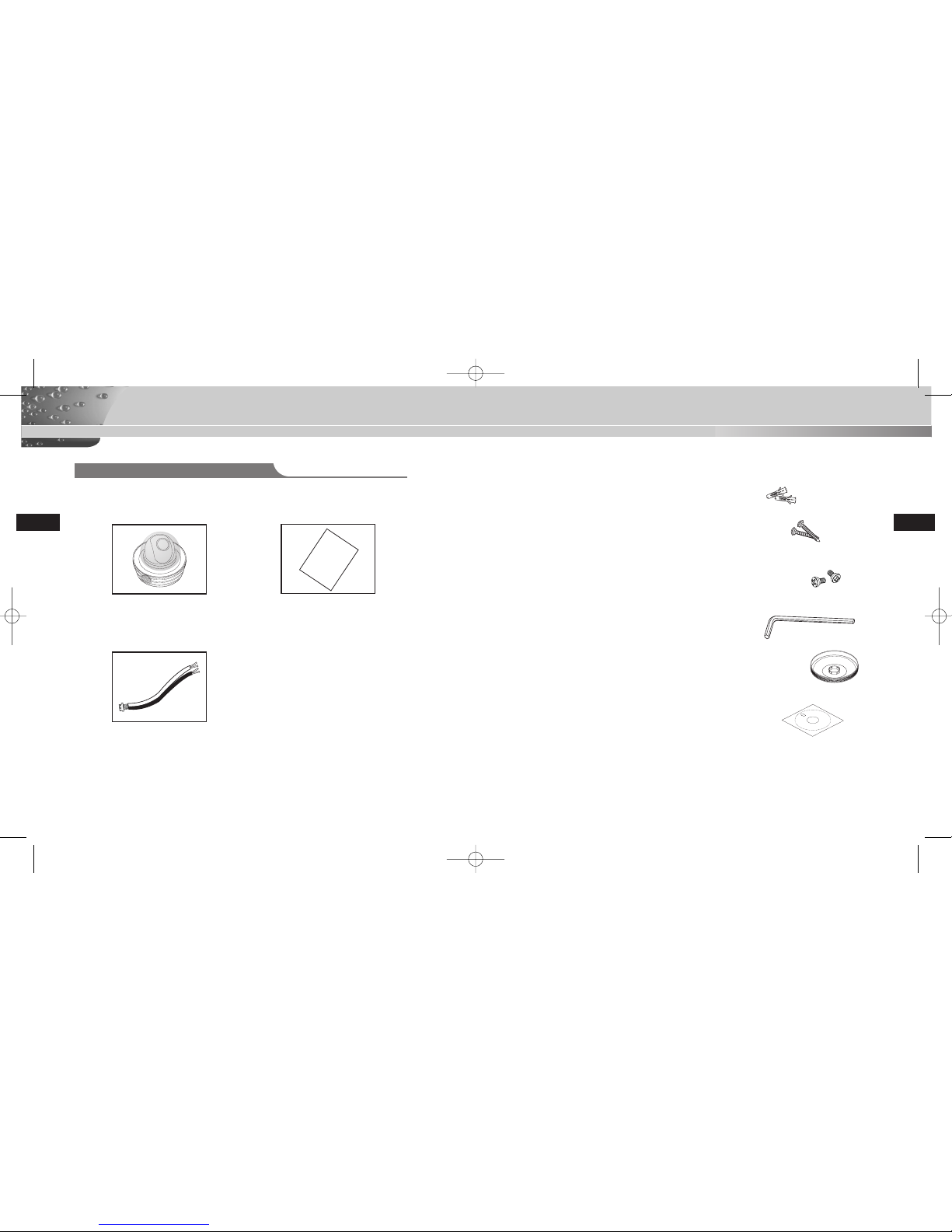
Checking the Contents of the Package
Be sure to check that the following items are included in the package.
Anti-Vandal Dome Camera
User’s Guide
ALARM & RS485 Cable
User’s Guide
✔ PLASTIC ANCHOR 2 ea. ❙❙for ceiling installation
✔ ASSY SCREW TAPPING 2 ea. ❙❙for ceiling installation
(TH M4 X L30 BLK + 0 RING)
✔ ASSY SCREW MACHINE 2 ea. ❙❙Attach to the holes at the
bottom for waterproof protection when installing the
camera on a pipe (CH M5 L8 XM7 + 0 RING)
✔ L WRENCH 1 ea. ❙❙for COVER DOME removal
✔ DECORATION-MOUNT 1 ea. ❙❙for covering the gap between
the ceiling and the PIPE when fastening using the PIPE
(ABS 94 V0)
✔ TEMPLET 1 ea. ❙❙An installation GUIDE for installing
on a ceiliing (ART PAPER)
00355A(01) SCC-931T(P)-eng 2006.1.10 1:49 PM Page 10

12
13
Before Installation
E E
Precautions for Installation and Use
Installation Examples
✔ Please check whether the installation site can sufficiently support the weight of
the Camera before installation.
✔ Make sure that the cable is not caught on anything or its insulation sheath is
not removed. (Neglecting to do so may cause fire or damage to the product.)
✔ Prevent people from approaching the installation area, where objects might fall
during installation. Move valuables to a safe location before installation.
✔ Install in a cool place and away from direct sunlight.
Be sure not expose the Camera to direct sunlight even during use or
storage. Use the BLC function when operating the Camera underneath a
spot light or under very bright lights.
✔ Use only in an area where temperature and humidity are kept within the limits
specified below:
- Operating Temperature: -10°C ~ +50°C (14°F~122°F)
- Humidity: Below 90%
✔ Use only the power source specified below:
- Power Consumption: 6W
- Voltage: DC 12V 600mA, AC 24V 300mA
✔ It can be directly installed on ceilings.
✔ It can be directly installed on pipes coming down from the ceiling.
✔ It can be directly installed on walls.
✔ It can be directly installed on pipes protruding from the wall.
✔ It can also be installed on corners of the building or on columns by using a
WALL MOUNT ADAPTER (SADT-101WM), CONER MOUNT ADAPTER
(SADT-110CM), or POLE MOUNT ADAPTER (SADT-100PM).
(These items are sold separately.)
00355A(01) SCC-931T(P)-eng 2006.1.10 1:49 PM Page 12
 Loading...