

Samsung SCC-833, SCC-833P, SCC-835, SCC-835P, SCC-803P Operating Instructions Manual
...
Super WDR & Low Light
Digital Color Camera
SCC-833(P)
SCC-835(P)
SCC-803P/805P
Part No.: AB68-00107A
Printed in Korea
Operating Instructions
00107A SCC-833P/855P - gb 11/22/00 3:36 PM Page 44

1
Operating Instructions
Contents
1. Introduction
.....................................................
2
2. Features
...........................................................
3
3. Installation
......................................................
5
Precautions in Installation and Use
......................
5
Connecting Auto Iris Lens Connector
.................
6
Mounting lens
.........................................................
7
Setting Lens Selection Switch
...............................
8
Adjusting Back Focus
............................................
9
Connecting Cable
.................................................
11
4. Name and Functions of Parts
......................
14
Name and Functions of Camera Parts
...............
14
Camera Setup
........................................................
19
5. Product Specifications
.................................
39
00107A SCC-833P/855P - gb 11/22/00 3:36 PM Page 1

2. Features
High Sensitivity
Adopting the Super-HAD CCD that has the latest
built-in microchip lens, the high sensitivity is
realized.
SWDR Function
With built-in SWDR (Super Wide Dynamic Range)
function using Dual Shutter method, distinction of
light and darkness is clear in areas where the
illumination levels differ greatly or the light source
is right behind the subject.
Low Illumination Function
It is possible to shoot in the worst situation where
there is no light by adopting a low illumination
function based on the Digital Signal Technology.
Excellent Back Light Compensation
Even when an intense light source or sunlight is in
the back of your subject, a clear image can be
provided due to the ideal combination of the
excellent performance of the high light
compression (Knee Compensation) function and
the BLC (Back Light Compensation) function.
3
Operating Instructions
1. Overview
Adopting the latest Super-HAD CCD (Charge
Coupled Device), the CCTV COLOR CAMERA
SCC-833(P)/835(P)/803P/805P are monitoring
camera which can provide the best monitoring
function when connected to the CCTV system
equipment by realizing SWDR (Super Wide
Dynamic Range) and low illumination function.
Broadcasting System
• SCC-833/835 : NTSC
• SCC-833P/835P/803P/805P : PAL
Number of CCD Pixel
• SCC-833 : 1/3" NTSC 410K
(High resolution type)
• SCC-835 : 1/2" NTSC 410K
(High resolution type)
• SCC-833P/803P : 1/3" PAL 470K
(High resolution type)
• SCC-835P/805P : 1/2" PAL 470K
(High resolution type)
Power Source
• SCC-833(P)/835(P): AC 24V, DC12V
• SCC-803P/805P : AC 220V ~ 240V
Operating Instructions
2
00107A SCC-833P/855P - gb 11/22/00 3:36 PM Page 2

5
Operating Instructions
Digital Line-lock
The control and reliability has been enhanced due
to the Full Digital Line Lock, which allows users to
adjust the Line Sync Phase.
Resolution
High resolution is realized due to the Full Digital
Image Processing utilizing the best Digital Signal
Technology.
Output Signal Selection
Video output signal reverse function and frame
setting (horizontal, vertical) function are
incorporated.
Remote Control
The operation of the camera can be remotely
controlled due to the built-in remote control
protocol of the RS-485 Standards.
* Remote control using PC requires additional
RS485/232C Interface Jig.
Operating Instructions
4
3. Installation
Precautions in Installation and Use
1) Do not attempt to disassemble the camera
yourself.
2) Be cautious in handling the camera. Avoid
striking or shaking the camera. Make sure to
avoid damage on the camera caused by improper
storage or operation.
3) Do not expose the camera to rain or moisture.
Do not operate the camera on a wet place.
4) Do not use strong or abrasive detergents when
cleaning the camera body. Use a dry cloth to
clean the camera.
5) Keep the camera at a cool place away from the
direct sunlight. Leaving the camera under the
direct sunlight may result in a malfunction of the
unit.
00107A SCC-833P/855P - gb 11/22/00 3:36 PM Page 4
7
Operating InstructionsOperating Instructions
6
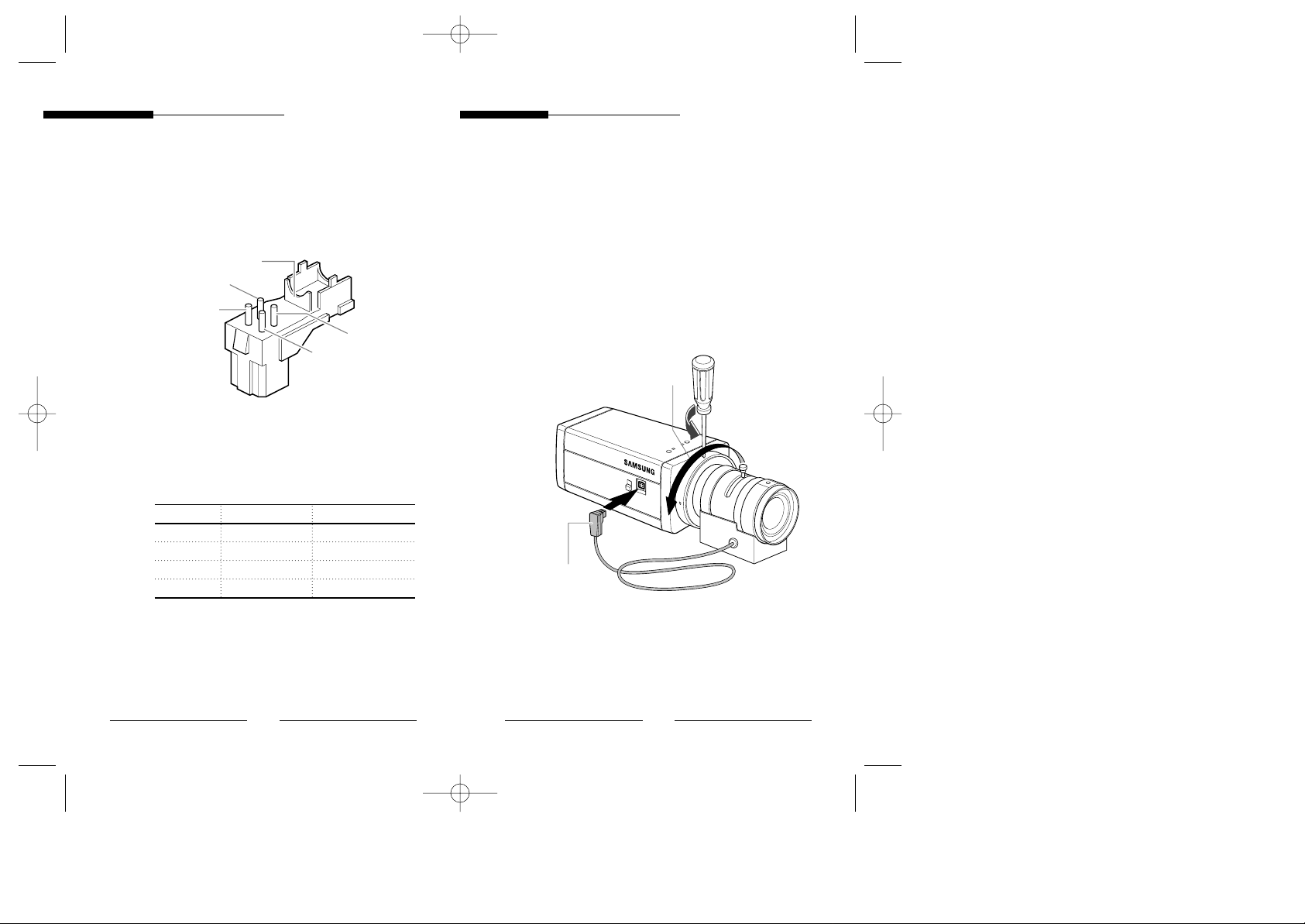
Connecting Auto Iris Lens Connector
Prepare the Auto Iris Lens Connector, which is
supplied along with the camera.
Connect the cable of the control cable, whose
covering is stripped, to the Auto Iris Lens
Connector as shown below.
Pin Number DC Control Type Video Control Type
1 Damp (–) Power (+9V)
2 Damp (+) Not used
3 Drive (+) Video signal
4 Drive (–) GND
Rib
Pin1
Pin2
Pin3
Pin4
Mounting the Lens
Loosen a screw fixing the Flange Back Adjustment
Ring by turning it counterclockwise and turn the
Adjustment Ring to the “C” direction
(counterclockwise) until it stops. Failure to do so
may result in a damage caused by a bump of the
lens against the image sensor part in the camera
when mounting the lens.
Auto Iris Control Cable
LENS
DC
VIDEO
C direction
00107A SCC-833P/855P - gb 11/22/00 3:36 PM Page 6
9
Operating InstructionsOperating Instructions
8
Setting Lens Selection Switch
When lens mounting is completed, set the Lens
Selection Switch on the lateral side of the camera
according to the type of lens mounted.
When the mounted lens is an Auto Iris Lens of DC
control type, set the Lens Selection Switch to “DC”.
When the mounted lens is an Auto Iris Lens of
video control type, set the Lens Selection Switch to
“VIDEO”.
LENS
DC
VIDEO
AI LENS AI LENS
DC DC
VIDEO VIDEO
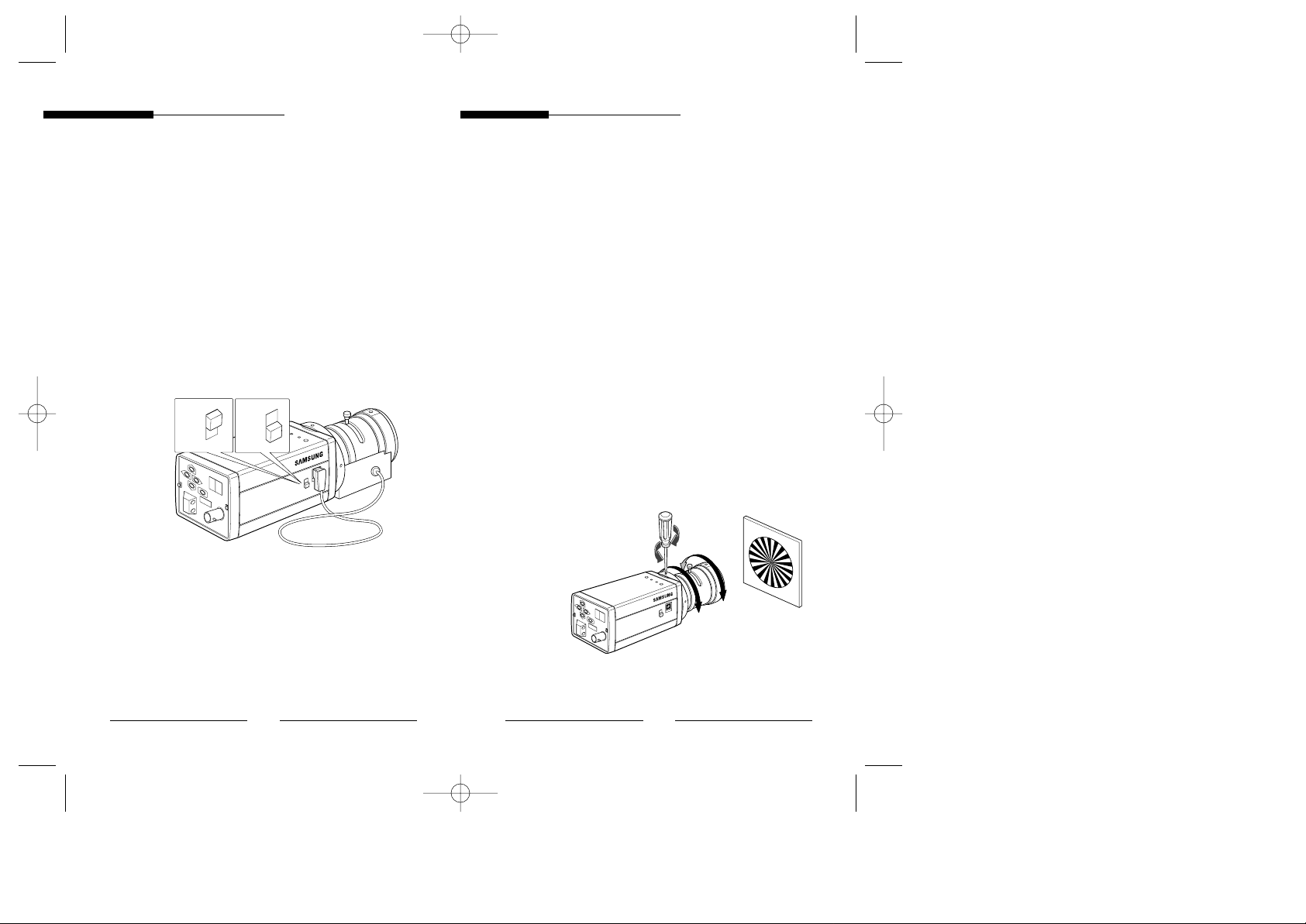
Adjusting Back Focus
Although the Back Focus of the camera has been
adjusted in the factory before its shipment, the
focus may not be accurate for a certain type of lens.
In this case, follow the procedures below to adjust
the back focus. First, following is how to adjust the
Back Focus of the Fixed Focus Lens.
1) Lightly loosen up the screw fixing the Back
Focus Adjustment Ring using a screwdriver.
2) Image a vivid subject (with check patterns) at a
distance of more than 10m away and turn the
Focus Ring to the infinity ( ∞ ) position.
3) Adjust the Back Focus Adjustment Ring to obtain
the clearest image of the subject.
4) Fasten the screw fixing the Back Focus
Adjustment Ring.
LENS
DC
VIDEO
00107A SCC-833P/855P - gb 11/22/00 3:36 PM Page 8
11
Operating InstructionsOperating Instructions
10
The following describes how to adjust the Back
Focus when using a Zoom Lens.
1) Lightly loosen up the screw fixing the Back
Focus Adjustment Ring using a screwdriver.
2) Image a vivid subject (with check patterns) at a
distance of 3 to 5 meters away and adjust the
zoom of the lens to TELE as far as it goes. Then
adjust the Focus Ring of the lens to obtain the
clearest image of the subject.
3)
Adjust the zoom of the lens to WIDE as far as it goes.
Then turn the Back Focus Ring of the camera to
obtain the clearest image of the subject.
4) Repeat the number 2) and 3) steps two to three
times to exactly coincide the zoom focus from
TELE with that from WIDE.
5) Fasten the screw fixing the Back Focus
Adjustment Ring.
Note:
Turning the Back Focus Adjustment Ring to the “C” direction
beyond the adjustable range makes a sound at the limit.
LENS
DC
VIDEO
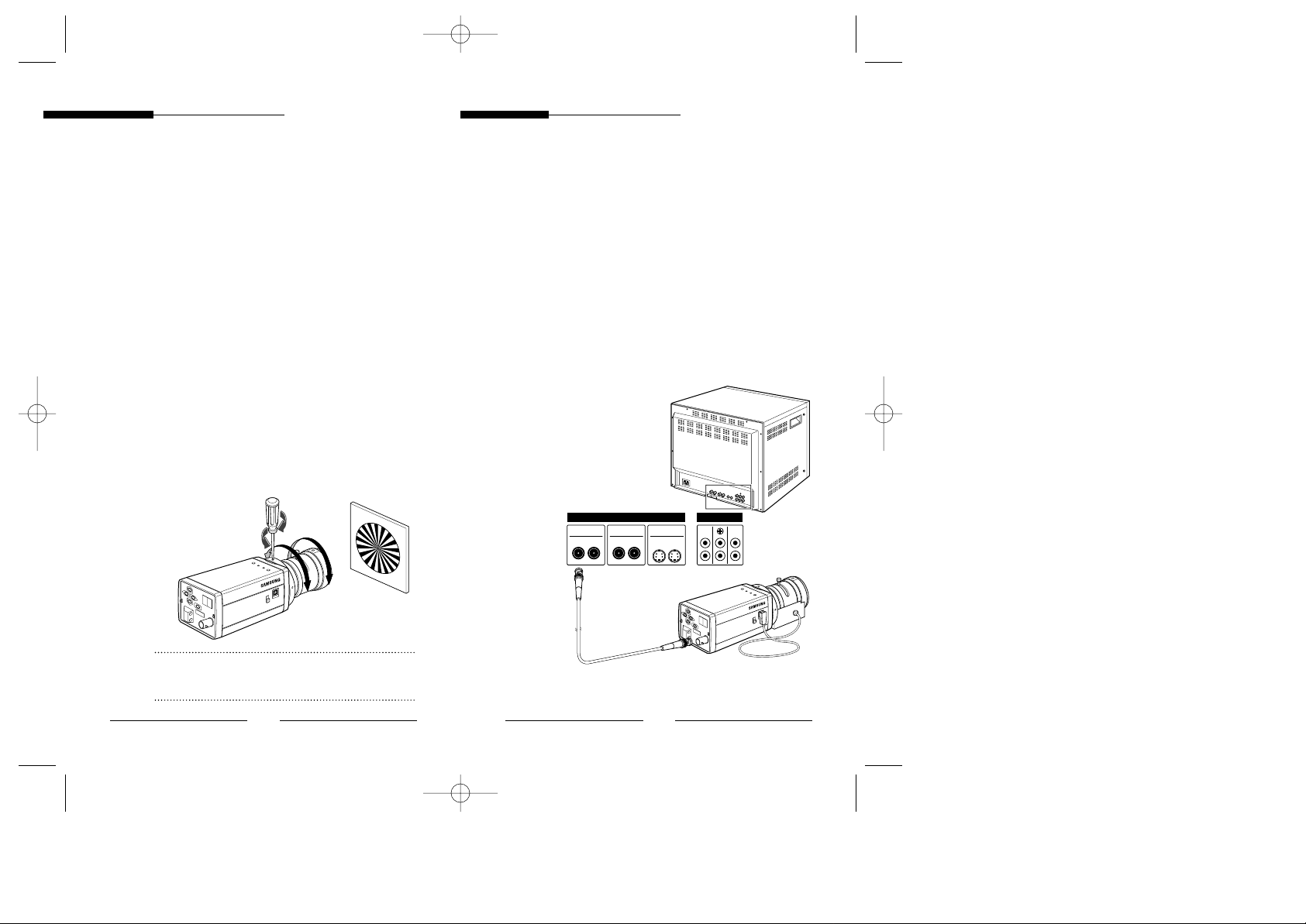
Connecting Cable
After mounting the lens and setting the Lens
Selection switch, connect the prepared cable to
each terminal of the camera.
1) First, connect one end of the BNC cable to the
Video Output Terminal (VIDEO OUT) of the
camera.
2) Then connect the other end of the BNC cable to
the Video Input Terminal of the camera.
LENS
IN
Video A
OUT IN
Video B
OUT IN
IN
Video C
OUT
OUT
ABC
VIDEO LINE AUDIO LINE
DC
VIDEO
Video In Terminal
on the rear of the monitor
BNC cable
Video Out Terminal
(VIDEO OUT)
00107A SCC-833P/855P - gb 11/22/00 3:36 PM Page 10
13
Operating InstructionsOperating Instructions
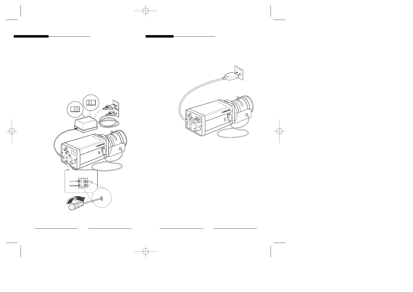
12
3) Then connect the power adapter.
As for SCC-833/P, 835/P, connect one end of two
lines of the power adapter using a screwdriver to
the Power In Terminal of the camera as shown
below.
* Connect to the AC 24V or DC 12V power
source, without the distinction of the polarity.
LENS
110
220
DC
VIDEO
AC24V
DC12V
4) Connect the power input cord to the AC 230V
power source. (SCC-803P/805P)
LENS
DC
VIDEO
00107A SCC-833P/855P - gb 11/22/00 3:36 PM Page 12
 Loading...