

Page 1
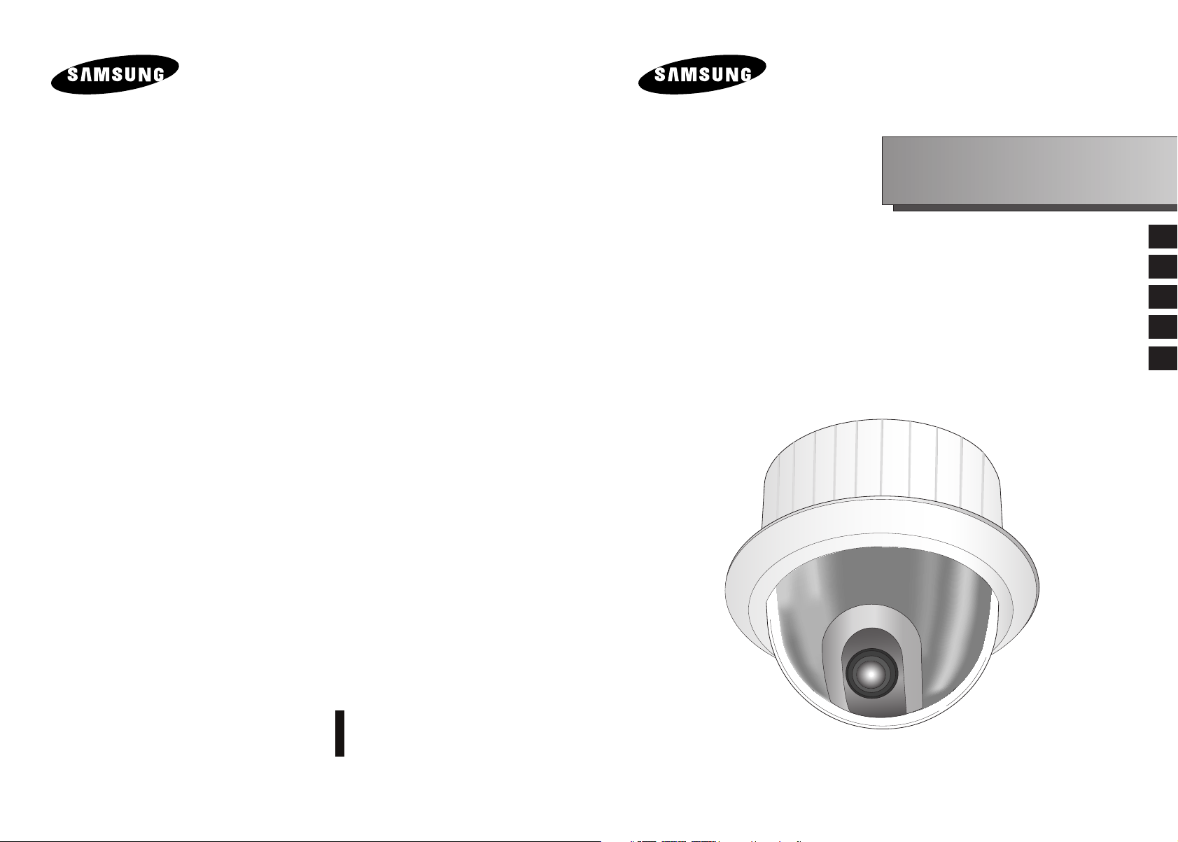
SmartDome Camera
SCC-643(P)
Owner’s Instructions
Benutzerhandbuch
Manuel d’instruction
Manual del usuario
Istruzioni per l’uso
E
D
F
Es
I
Part : AB68-00357A(02)
Printed in China
Page 2
Safety Precautions
The purpose of this information is to ensure proper use of this product to
prevent danger or damage to property. Please be sure to observe all
precautions.
* The precautions are divided into "Warnings" and "Cautions" as
distinguished below:
Warning: Ignoring this warning may result in death or serious injury.
Caution: Ignoring this caution may result in injury or damage to property.
Warning instructions alert you to
a potential risk of death
or serious injury.
Caution instructions alert you to the
potential risk of injury or
damage to property.
Warning
1. Be sure to use only the supplied adapter.
(Using an adapter other than the one supplied may cause fire, electrical
shock, or damage to the product.)
2. When connecting the power supply and signal wires, check the external
connection terminals before connecting them. Connect the alarm signal
wires to the alarm terminals, the AC adapter to the AC power input
receptacle, and the DC adapter to the DC power input, making sure that
the correct polarity is observed.
(Connecting the power supply incorrectly may cause fire, electrical shock,
or damage to the product.)
3. Do not connect multiple cameras to a single adapter.
(Exceeding the capacity may cause abnormal heat generation or fire.)
(A falling camera may cause personal injury.)
4. Securely plug the power cord into the power receptacle.
(Insecure connection may cause fire.)
5. When installing the camera on a wall or ceiling, fasten it securely and
firmly. (A falling camera may cause personal injury.)
6. Do not place conductive objects (e.g., screwdrivers, coins, and metal
things) or containers filled with water on top of the camera. (Doing so may
cause personal injury due to fire, electrical shock, or falling objects.)
7. Do not install the unit in humid, dusty, or sooty locations.
(Doing so may cause fire or electrical shock.)
8. If any unusual smells or smoke come from the unit, stop using the product.
In such case, immediately disconnect the power source and contact the
service center. (Continued use in such a condition may cause fire or
electrical shock.)
9. If this product fails to operate normally, contact the store of purchase or
your nearest service center. Never disassemble or modify this product in
any way. (SAMSUNG is not liable for problems caused by unauthorized
modifications or attempted repair.)
10. When cleaning, do not spray water directly onto parts of the product.
(Doing so may cause fire or electrical shock.)
Wipe the surface with a dry cloth. Never use detergents or chemical
cleaners on the product, as this may result in discoloration of surface or
cause damage to the finish.
Caution
1. Do not drop objects on the product or apply strong shock to it. Keep away
from a location subject to excessive vibration or magnetic interference.
°F
), low
2. Do not install in a location subject to high temperature (over
temperature (below 14°F
(Doing so may cause fire or electrical shock.)
3. Avoid a location which is exposed to direct sunlight, or near heat sources
such as heaters or radiators.
(Neglecting to do so may result in a risk of fire.)
4. If you want to relocate the already installed product, be sure to turn off the
power and then move or reinstall it.
5. Install in a well-ventilated location.
6. Remove the power plug from the outlet when there is a lightning storm.
(Neglecting to do so may cause fire or damage to the product.)
), or high humidity.
122
E
Page 3
Before Usage
This is a basic instruction manual for the SCC-643(P) user.
It contains all the instructions needed to use the SCC-643(P) from
a simple introduction of the control locations and functions of the
SCC-643(P) to installation methods in the set up menu.
Approval of Standards
We recommend all users of the SCC-643(P) from the advanced
user who has used similar cameras before to the general user to
read the instruction manual before using.
The most frequently used feature in the SCC-643(P) would be the
SCC-643(P) Setup Menu.
The SCC-643(P) Setup Menu is explained in detailed in "Chapter
3 Setup Menu Overview".
The instructional manual is best used when read from beginning
to end, but for users wanting to read only the part they need here
are the Chapter summaries.
"Chapter 1 SCC-643(P) Overview" includes a brief introduction
of the SCC-643(P), part names and functions, and Switch
Settings.
"Chapter 2 SCC-643(P) Installation" explains the installation
procedures of the SCC-643(P) and provides preparation and
installation environment requirements.
E
Note: This equipment has been tested and found to comply with the limits for a Class B
digital device, pursuant to part 15 of the FCC Rules. These limits are designed to provide
reasonable protection against harmful interface in a residential installation. This equipment
generates, uses and can radiate radio frequency energy and, if not installed and used in
accordance with the instructions, may cause harmful interference to radio communications.
However, there is no guarantee that interference will not occur in a particular installation.
If this equipment does cause harmful interference to radio or television reception, which can
be determined by turning the equipment off and on, the user is encouraged to try to correct
the interference by one or more of the following measures:
- Reorient of relocate the receiving antenna.
- Increase the separation between the equipment and receiver.
- Connect the equipment into an outlet on a circuit different from that to which
the receiver is connected.
- Consult the dealer or an experienced radio TV technician for help.
"Chapter 3 Setup Menu Overview" presents the structure of the
Setup menu for the SCC-643(P) including a detailed explanation
of the functions performed in each submenu.
"Appendix SCC-643(P) Product Specifications" contains
product specifications of the SCC-643(P) in itemized categories.
1-1
1-2
Page 4

Table of contents
Before Usage --------------------------------------------------------------------------------------1-1
Chapter 1 SCC-643(P) Overview -----------------------------------------------------------1-5
SCC-643(P) Introduction---------------------------------------------------------1-6
SCC-643(P)Locations of Control-----------------------------------------------1-7
SCC-643(P) FRONT --------------------------------------------------------------1-7
SCC-643(P) BACK ----------------------------------------------------------------1-8
ADAPTER CONNECTION-------------------------------------------------------1-9
INITIAL SETTING ----------------------------------------------------------------1-10
Setting RS-422A/RS-485 termination ---------------------------------------1-11
SWITCH SETTING --------------------------------------------------------------1-12
Chapter 2 SCC-643(P) Installation---------------------------------------------------------2-1
Before Installing
Preparing the Cables
Cable Connection
Installing SCC-643(P)
Installing the Camera
Chapter 3 Setup Menu Overview-----------------------------------------------------------3-1
Structure of the Setup Menu
1. CAMERA SET MENU ---------------------------------------------------------3-4
- CAMERA ID--------------------------------------------------------------------3-4
- V-SYNC -------------------------------------------------------------------------3-4
- COLOR/BW --------------------------------------------------------------------3-5
- ZOOM SPEED ----------------------------------------------------------------3-6
- MOTION DET------------------------------------------------------------------3-6
- EXIT------------------------------------------------------------------------------3-7
2. VIDEO SET MENU-------------------------------------------------------------3-7
- IRIS-------------------------------------------------------------------------------3-7
- ALC-------------------------------------------------------------------------------3-8
- BLC-------------------------------------------------------------------------------3-8
- MANU----------------------------------------------------------------------------3-9
- SHUTTER ----------------------------------------------------------------------3-9
-------------------------------------------------------------------2-2
-----------------------------------------------------------2-3
-----------------------------------------------------------------2-4
-----------------------------------------------------------2-5
------------------------------------------------------------2-8
--------------------------------------------------3-2
- AGC ----------------------------------------------------------------------------3-10
- S.S ------------------------------------------------------------------------------3-10
- SLOW --------------------------------------------------------------------------3-11
- NORMAL ----------------------------------------------------------------------3-11
- FAST ---------------------------------------------------------------------------3-11
- F.F ------------------------------------------------------------------------------3-11
- WHITE BAL-------------------------------------------------------------------3-12
- SPECIAL ----------------------------------------------------------------------3-14
- AUTO FOCUS ---------------------------------------------------------------3-15
- D-ZOOM-----------------------------------------------------------------------3-15
- EXIT ----------------------------------------------------------------------------3-15
3. PRESET-------------------------------------------------------------------------3-16
4. AUTO MODE-------------------------------------------------------------------3-18
- AUTO PAN -------------------------------------------------------------------3-18
- PATTERN---------------------------------------------------------------------3-19
5. ALARM SET--------------------------------------------------------------------3-20
6. OTHER SET--------------------------------------------------------------------3-22
Appendix Product specifications --------------------------------------------------------3-25
E
1-3
1-4
Page 5

Chapter 1 SCC-643(P) Overview
In this chapter we will briefly introduce the SCC-643(P) and show
main functions, locations of control and Switch Setting.
SCC-643(P) Introduction
The SCC-643(P) is the best performing zoom lens integrated
surveillance camera. It can be used with CCTV in banks or
companies to provide high level of security.
The SCC-643(P) is a high quality surveillance camera using x22
zoom lens and digital zoom IC, it can catch clear images up to
220 times.
The SCC-643(P) is a multifunction camera that is equipped with all
of the key functions of the existing surveillance cameras:
- Low-Light Surveillance function that enables image
capture even under extremely low light conditions.
- White Balance function that provides accurate color
rendition under any light conditions.
- BLC function that enables effective back light
compensation even under a spotlight or a very bright
incident light.
- Auto-Focus function that automatically tracks and focuses
on the moving subject.
- Privacy Zone function that hides certain area of the screen
from view to protect individual privacy.
- COLOR/BW function that automatically switches to the BW
(Black and White) mode to increase the camera's
sensitivity at night or under low light level conditions.
E
1-5
The SCC-643(P) uses an Alarm function for alert situations and
moving camera in the direction you want, ZOOM-IN and
ZOOM-OUT functions can be remote controlled.
1-6
Page 6
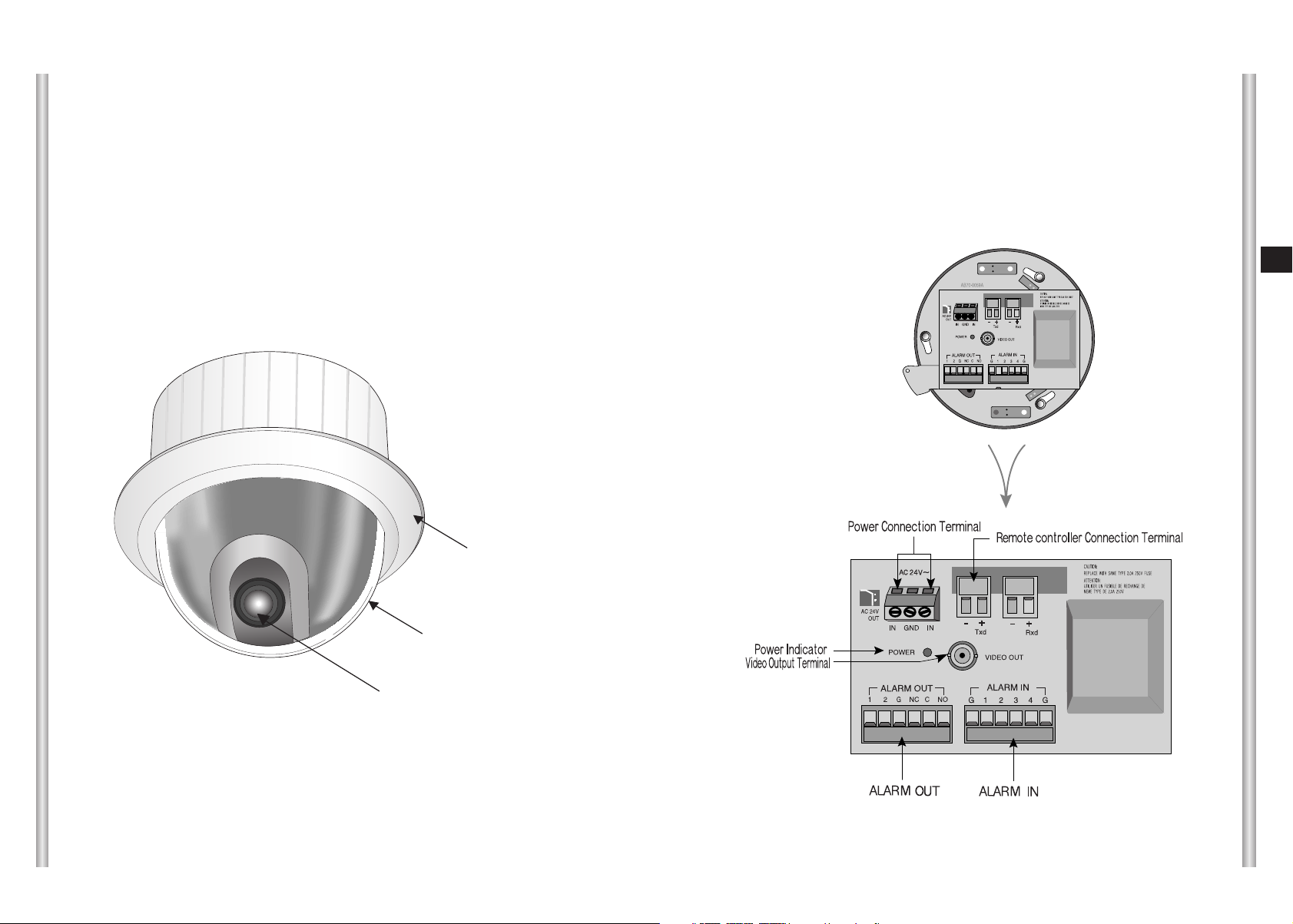
Locations of Control
FRONT
BACK
E
COVER BODY
COVER DOME
1-7
ZOOM LENS
1-8
Page 7
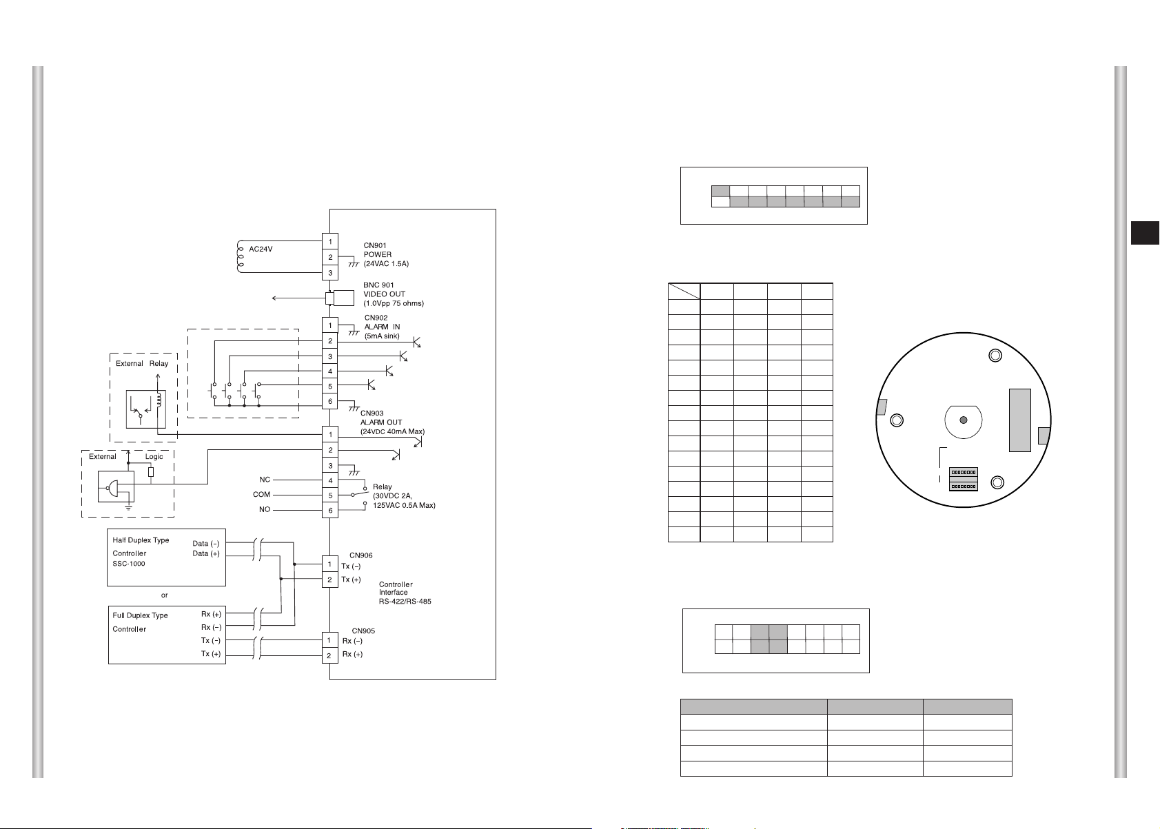
SW501
SW500
SEE INSTRUCTION MANUAL
ADAPTER CONNECTION
INITIAL SETTING
CAMERA ADDRESS SETUP
Dip Switch setting is same as the following example:
EX) CAMERA ADDR: When it's number 1, set as follows.
SCC-643(P) Adapter BOARD
1 2 3 4 5 6 7 8
ON
OFF
SW500
Setting communication Protocol
Use number 5~8 PIN of SW501 to set communication Protocol.
PIN
PIN5 PIN6 PIN7 PIN8
Comp
A OFF OFF OFF OFF
B ON OFF OFF OFF
C OFF ON OFF OFF
D ON ON OFF OFF
E OFF OFF ON OFF
F ON OFF ON OFF
G OFF ON ON OFF
H ON ON ON OFF
I OFF OFF OFF ON
J ON OFF OFF ON
K OFF ON OFF ON
L ON ON OFF ON
M OFF OFF ON ON
N ON OFF ON ON
O OFF ON ON ON
PONONONON
A : SAMSUNG(SSC-1000)HALF
B : SAMSUNG FULL
(BOTTOM VIEW)
Baud Rate Setting
Use PIN 3 and 4 of SW501.
E
1-9
1 2 3 4 5 6 7 8
ON
OFF
SW 501
BAUD RATE
4800 BPS
9600 BPS
19200 BPS
38400 BPS
PIN 3
ON
OFF
ON
OFF
PIN 4
ON
ON
OFF
OFF
1-10
Page 8
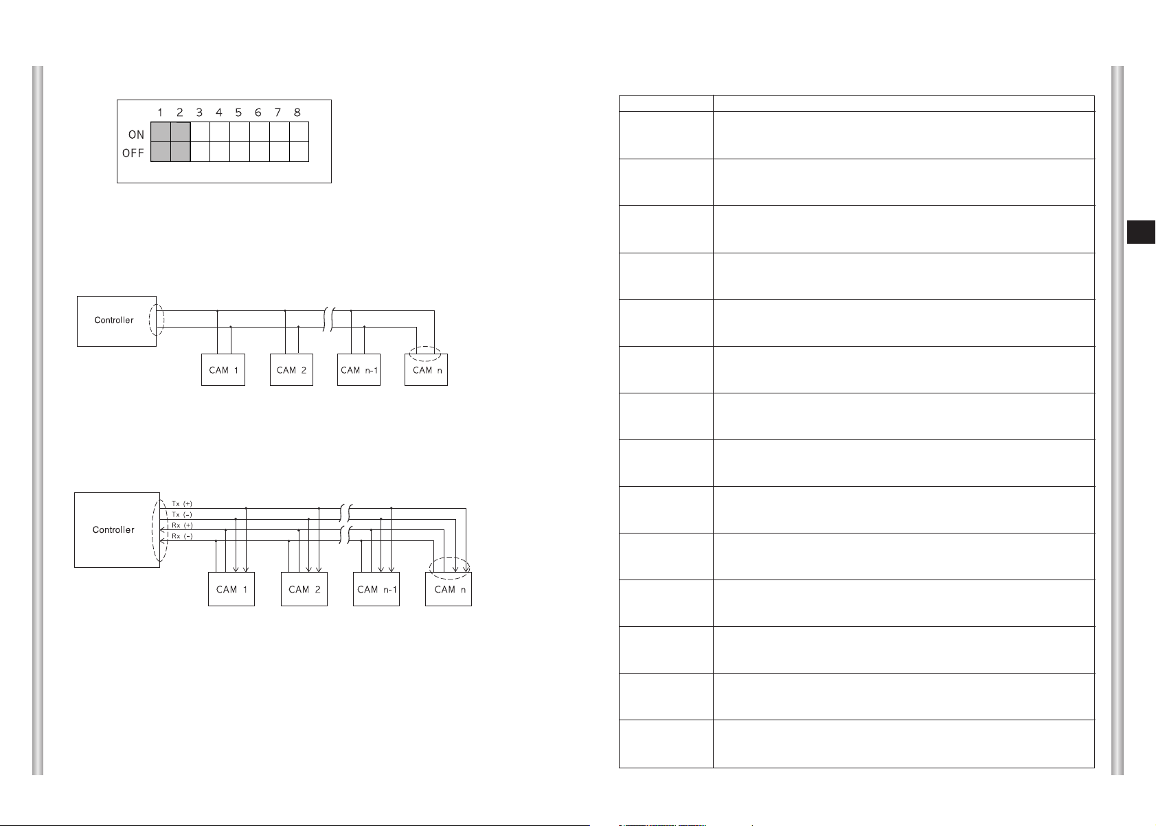
Setting RS-422A/RS-485 termination
SWITCH SETTING
SW 501
As it is shown in the structure map, when Controller and RS-422A/RS-485
is connected it should be terminated according to the Cable feature of
impedance on the each end of the transmitting line to transfer the signals in
long distance by controlling the reflection of the signals to the lowest.
Division
<RS-485 Half Duplex Organization>
n < 128
Termination
SW1-ON
Termination: using numbers 1 and 2 PIN, turn to ON and it will be terminated.
n < 128
Division
SW1-ON
Division
<RS-422A/RS-485 Full Duplex Organization>
SW2-ON
Receiver Address
0
1
2
3
4
5
6
7
8
9
10
11
12
13
14
15
16
17
18
19
20
21
22
23
24
25
26
27
28
29
30
31
32
33
34
35
36
37
38
39
40
41
42
43
44
45
46
47
48
49
50
51
52
53
54
55
SW500-1
OFF
ON
OFF
ON
OFF
ON
OFF
ON
OFF
ON
OFF
ON
OFF
ON
OFF
ON
OFF
ON
OFF
ON
OFF
ON
OFF
ON
OFF
ON
OFF
ON
OFF
ON
OFF
ON
OFF
ON
OFF
ON
OFF
ON
OFF
ON
OFF
ON
OFF
ON
OFF
ON
OFF
ON
OFF
ON
OFF
ON
OFF
ON
OFF
ON
SW500-2
OFF
OFF
ON
ON
OFF
OFF
ON
ON
OFF
OFF
ON
ON
OFF
OFF
ON
ON
OFF
OFF
ON
ON
OFF
OFF
ON
ON
OFF
OFF
ON
ON
OFF
OFF
ON
ON
OFF
OFF
ON
ON
OFF
OFF
ON
ON
OFF
OFF
ON
ON
OFF
OFF
ON
ON
OFF
OFF
ON
ON
OFF
OFF
ON
ON
SW500-3
OFF
OFF
OFF
OFF
ON
ON
ON
ON
OFF
OFF
OFF
OFF
ON
ON
ON
ON
OFF
OFF
OFF
OFF
ON
ON
ON
ON
OFF
OFF
OFF
OFF
ON
ON
ON
ON
OFF
OFF
OFF
OFF
ON
ON
ON
ON
OFF
OFF
OFF
OFF
ON
ON
ON
ON
OFF
OFF
OFF
OFF
ON
ON
ON
ON
SW500-4
OFF
OFF
OFF
OFF
OFF
OFF
OFF
OFF
ON
ON
ON
ON
ON
ON
ON
ON
OFF
OFF
OFF
OFF
OFF
OFF
OFF
OFF
ON
ON
ON
ON
ON
ON
ON
ON
OFF
OFF
OFF
OFF
OFF
OFF
OFF
OFF
ON
ON
ON
ON
ON
ON
ON
ON
OFF
OFF
OFF
OFF
OFF
OFF
OFF
OFF
SW500-5
OFF
OFF
OFF
OFF
OFF
OFF
OFF
OFF
OFF
OFF
OFF
OFF
OFF
OFF
OFF
OFF
ON
ON
ON
ON
ON
ON
ON
ON
ON
ON
ON
ON
ON
ON
ON
ON
OFF
OFF
OFF
OFF
OFF
OFF
OFF
OFF
OFF
OFF
OFF
OFF
OFF
OFF
OFF
OFF
ON
ON
ON
ON
ON
ON
ON
ON
SW500-6
OFF
OFF
OFF
OFF
OFF
OFF
OFF
OFF
OFF
OFF
OFF
OFF
OFF
OFF
OFF
OFF
OFF
OFF
OFF
OFF
OFF
OFF
OFF
OFF
OFF
OFF
OFF
OFF
OFF
OFF
OFF
OFF
ON
ON
ON
ON
ON
ON
ON
ON
ON
ON
ON
ON
ON
ON
ON
ON
ON
ON
ON
ON
ON
ON
ON
ON
SW500-7
OFF
OFF
OFF
OFF
OFF
OFF
OFF
OFF
OFF
OFF
OFF
OFF
OFF
OFF
OFF
OFF
OFF
OFF
OFF
OFF
OFF
OFF
OFF
OFF
OFF
OFF
OFF
OFF
OFF
OFF
OFF
OFF
OFF
OFF
OFF
OFF
OFF
OFF
OFF
OFF
OFF
OFF
OFF
OFF
OFF
OFF
OFF
OFF
OFF
OFF
OFF
OFF
OFF
OFF
OFF
OFF
SW500-8
OFF
OFF
OFF
OFF
OFF
OFF
OFF
OFF
OFF
OFF
OFF
OFF
OFF
OFF
OFF
OFF
OFF
OFF
OFF
OFF
OFF
OFF
OFF
OFF
OFF
OFF
OFF
OFF
OFF
OFF
OFF
OFF
OFF
OFF
OFF
OFF
OFF
OFF
OFF
OFF
OFF
OFF
OFF
OFF
OFF
OFF
OFF
OFF
OFF
OFF
OFF
OFF
OFF
OFF
OFF
OFF
E
1-11
1-12
Page 9

1-13
Receiver Address
56
57
58
59
60
61
62
63
64
65
66
67
68
69
70
71
72
73
74
75
76
77
78
79
80
81
82
83
84
85
86
87
88
89
90
91
92
93
94
95
96
97
98
99
100
101
102
103
104
105
106
107
108
109
110
111
112
113
114
115
SW500-1
OFF
ON
OFF
ON
OFF
ON
OFF
ON
OFF
ON
OFF
ON
OFF
ON
OFF
ON
OFF
ON
OFF
ON
OFF
ON
OFF
ON
OFF
ON
OFF
ON
OFF
ON
OFF
ON
OFF
ON
OFF
ON
OFF
ON
OFF
ON
OFF
ON
OFF
ON
OFF
ON
OFF
ON
OFF
ON
OFF
ON
OFF
ON
OFF
ON
OFF
ON
OFF
ON
SW500-2
OFF
OFF
ON
ON
OFF
OFF
ON
ON
OFF
OFF
ON
ON
OFF
OFF
ON
ON
OFF
OFF
ON
ON
OFF
OFF
ON
ON
OFF
OFF
ON
ON
OFF
OFF
ON
ON
OFF
OFF
ON
ON
OFF
OFF
ON
ON
OFF
OFF
ON
ON
OFF
OFF
ON
ON
OFF
OFF
ON
ON
OFF
OFF
ON
ON
OFF
OFF
ON
ON
SW500-3
OFF
OFF
OFF
OFF
ON
ON
ON
ON
OFF
OFF
OFF
OFF
ON
ON
ON
ON
OFF
OFF
OFF
OFF
ON
ON
ON
ON
OFF
OFF
OFF
OFF
ON
ON
ON
ON
OFF
OFF
OFF
OFF
ON
ON
ON
ON
OFF
OFF
OFF
OFF
ON
ON
ON
ON
OFF
OFF
OFF
OFF
ON
ON
ON
ON
OFF
OFF
OFF
OFF
SW500-4
ON
ON
ON
ON
ON
ON
ON
ON
OFF
OFF
OFF
OFF
OFF
OFF
OFF
OFF
ON
ON
ON
ON
ON
ON
ON
ON
OFF
OFF
OFF
OFF
OFF
OFF
OFF
OFF
ON
ON
ON
ON
ON
ON
ON
ON
OFF
OFF
OFF
OFF
OFF
OFF
OFF
OFF
ON
ON
ON
ON
ON
ON
ON
ON
OFF
OFF
OFF
OFF
SW500-5
ON
ON
ON
ON
ON
ON
ON
ON
OFF
OFF
OFF
OFF
OFF
OFF
OFF
OFF
OFF
OFF
OFF
OFF
OFF
OFF
OFF
OFF
ON
ON
ON
ON
ON
ON
ON
ON
ON
ON
ON
ON
ON
ON
ON
ON
OFF
OFF
OFF
OFF
OFF
OFF
OFF
OFF
OFF
OFF
OFF
OFF
OFF
OFF
OFF
OFF
ON
ON
ON
ON
SW500-6
ON
ON
ON
ON
ON
ON
ON
ON
OFF
OFF
OFF
OFF
OFF
OFF
OFF
OFF
OFF
OFF
OFF
OFF
OFF
OFF
OFF
OFF
OFF
OFF
OFF
OFF
OFF
OFF
OFF
OFF
OFF
OFF
OFF
OFF
OFF
OFF
OFF
OFF
ON
ON
ON
ON
ON
ON
ON
ON
ON
ON
ON
ON
ON
ON
ON
ON
ON
ON
ON
ON
SW500-7
OFF
OFF
OFF
OFF
OFF
OFF
OFF
OFF
ON
ON
ON
ON
ON
ON
ON
ON
ON
ON
ON
ON
ON
ON
ON
ON
ON
ON
ON
ON
ON
ON
ON
ON
ON
ON
ON
ON
ON
ON
ON
ON
ON
ON
ON
ON
ON
ON
ON
ON
ON
ON
ON
ON
ON
ON
ON
ON
ON
ON
ON
ON
SW500-8
OFF
OFF
OFF
OFF
OFF
OFF
OFF
OFF
OFF
OFF
OFF
OFF
OFF
OFF
OFF
OFF
OFF
OFF
OFF
OFF
OFF
OFF
OFF
OFF
OFF
OFF
OFF
OFF
OFF
OFF
OFF
OFF
OFF
OFF
OFF
OFF
OFF
OFF
OFF
OFF
OFF
OFF
OFF
OFF
OFF
OFF
OFF
OFF
OFF
OFF
OFF
OFF
OFF
OFF
OFF
OFF
OFF
OFF
OFF
OFF
Receiver Address
116
117
118
119
120
121
122
123
124
125
126
127
128
129
130
131
132
133
134
135
136
137
138
139
140
141
142
143
144
145
146
147
148
149
150
151
152
153
154
155
156
157
158
159
160
161
162
163
164
165
166
167
168
169
170
171
172
173
174
175
SW500-1
OFF
ON
OFF
ON
OFF
ON
OFF
ON
OFF
ON
OFF
ON
OFF
ON
OFF
ON
OFF
ON
OFF
ON
OFF
ON
OFF
ON
OFF
ON
OFF
ON
OFF
ON
OFF
ON
OFF
ON
OFF
ON
OFF
ON
OFF
ON
OFF
ON
OFF
ON
OFF
ON
OFF
ON
OFF
ON
OFF
ON
OFF
ON
OFF
ON
OFF
ON
OFF
ON
SW500-2
OFF
OFF
ON
ON
OFF
OFF
ON
ON
OFF
OFF
ON
ON
OFF
OFF
ON
ON
OFF
OFF
ON
ON
OFF
OFF
ON
ON
OFF
OFF
ON
ON
OFF
OFF
ON
ON
OFF
OFF
ON
ON
OFF
OFF
ON
ON
OFF
OFF
ON
ON
OFF
OFF
ON
ON
OFF
OFF
ON
ON
OFF
OFF
ON
ON
OFF
OFF
ON
ON
SW500-3
ON
ON
ON
ON
OFF
OFF
OFF
OFF
ON
ON
ON
ON
OFF
OFF
OFF
OFF
ON
ON
ON
ON
OFF
OFF
OFF
OFF
ON
ON
ON
ON
OFF
OFF
OFF
OFF
ON
ON
ON
ON
OFF
OFF
OFF
OFF
ON
ON
ON
ON
OFF
OFF
OFF
OFF
ON
ON
ON
ON
OFF
OFF
OFF
OFF
ON
ON
ON
ON
SW500-4
OFF
OFF
OFF
OFF
ON
ON
ON
ON
ON
ON
ON
ON
OFF
OFF
OFF
OFF
OFF
OFF
OFF
OFF
ON
ON
ON
ON
ON
ON
ON
ON
OFF
OFF
OFF
OFF
OFF
OFF
OFF
OFF
ON
ON
ON
ON
ON
ON
ON
ON
OFF
OFF
OFF
OFF
OFF
OFF
OFF
OFF
ON
ON
ON
ON
ON
ON
ON
ON
SW500-5
ON
ON
ON
ON
ON
ON
ON
ON
ON
ON
ON
ON
OFF
OFF
OFF
OFF
OFF
OFF
OFF
OFF
OFF
OFF
OFF
OFF
OFF
OFF
OFF
OFF
ON
ON
ON
ON
ON
ON
ON
ON
ON
ON
ON
ON
ON
ON
ON
ON
OFF
OFF
OFF
OFF
OFF
OFF
OFF
OFF
OFF
OFF
OFF
OFF
OFF
OFF
OFF
OFF
SW500-6
ON
ON
ON
ON
ON
ON
ON
ON
ON
ON
ON
ON
OFF
OFF
OFF
OFF
OFF
OFF
OFF
OFF
OFF
OFF
OFF
OFF
OFF
OFF
OFF
OFF
OFF
OFF
OFF
OFF
OFF
OFF
OFF
OFF
OFF
OFF
OFF
OFF
OFF
OFF
OFF
OFF
ON
ON
ON
ON
ON
ON
ON
ON
ON
ON
ON
ON
ON
ON
ON
ON
SW500-7
ON
ON
ON
ON
ON
ON
ON
ON
ON
ON
ON
ON
OFF
OFF
OFF
OFF
OFF
OFF
OFF
OFF
OFF
OFF
OFF
OFF
OFF
OFF
OFF
OFF
OFF
OFF
OFF
OFF
OFF
OFF
OFF
OFF
OFF
OFF
OFF
OFF
OFF
OFF
OFF
OFF
OFF
OFF
OFF
OFF
OFF
OFF
OFF
OFF
OFF
OFF
OFF
OFF
OFF
OFF
OFF
OFF
SW500-8
OFF
OFF
OFF
OFF
OFF
OFF
OFF
OFF
OFF
OFF
OFF
OFF
ON
ON
ON
ON
ON
ON
ON
ON
ON
ON
ON
ON
ON
ON
ON
ON
ON
ON
ON
ON
ON
ON
ON
ON
ON
ON
ON
ON
ON
ON
ON
ON
ON
ON
ON
ON
ON
ON
ON
ON
ON
ON
ON
ON
ON
ON
ON
ON
E
1-14
Page 10

Receiver Address
176
177
178
179
180
181
182
183
184
185
186
187
188
189
190
191
192
193
194
195
196
197
198
199
200
201
202
203
204
205
206
207
208
209
210
211
212
213
214
215
216
217
218
219
220
221
222
223
224
225
226
227
228
229
230
231
232
233
234
235
SW500-1
OFF
ON
OFF
ON
OFF
ON
OFF
ON
OFF
ON
OFF
ON
OFF
ON
OFF
ON
OFF
ON
OFF
ON
OFF
ON
OFF
ON
OFF
ON
OFF
ON
OFF
ON
OFF
ON
OFF
ON
OFF
ON
OFF
ON
OFF
ON
OFF
ON
OFF
ON
OFF
ON
OFF
ON
OFF
ON
OFF
ON
OFF
ON
OFF
ON
OFF
ON
OFF
ON
SW500-2
OFF
OFF
ON
ON
OFF
OFF
ON
ON
OFF
OFF
ON
ON
OFF
OFF
ON
ON
OFF
OFF
ON
ON
OFF
OFF
ON
ON
OFF
OFF
ON
ON
OFF
OFF
ON
ON
OFF
OFF
ON
ON
OFF
OFF
ON
ON
OFF
OFF
ON
ON
OFF
OFF
ON
ON
OFF
OFF
ON
ON
OFF
OFF
ON
ON
OFF
OFF
ON
ON
SW500-3
OFF
OFF
OFF
OFF
ON
ON
ON
ON
OFF
OFF
OFF
OFF
ON
ON
ON
ON
OFF
OFF
OFF
OFF
ON
ON
ON
ON
OFF
OFF
OFF
OFF
ON
ON
ON
ON
OFF
OFF
OFF
OFF
ON
ON
ON
ON
OFF
OFF
OFF
OFF
ON
ON
ON
ON
OFF
OFF
OFF
OFF
ON
ON
ON
ON
OFF
OFF
OFF
OFF
SW500-4
OFF
OFF
OFF
OFF
OFF
OFF
OFF
OFF
ON
ON
ON
ON
ON
ON
ON
ON
OFF
OFF
OFF
OFF
OFF
OFF
OFF
OFF
ON
ON
ON
ON
ON
ON
ON
ON
OFF
OFF
OFF
OFF
OFF
OFF
OFF
OFF
ON
ON
ON
ON
ON
ON
ON
ON
OFF
OFF
OFF
OFF
OFF
OFF
OFF
OFF
ON
ON
ON
ON
SW500-5
ON
ON
ON
ON
ON
ON
ON
ON
ON
ON
ON
ON
ON
ON
ON
ON
OFF
OFF
OFF
OFF
OFF
OFF
OFF
OFF
OFF
OFF
OFF
OFF
OFF
OFF
OFF
OFF
ON
ON
ON
ON
ON
ON
ON
ON
ON
ON
ON
ON
ON
ON
ON
ON
OFF
OFF
OFF
OFF
OFF
OFF
OFF
OFF
OFF
OFF
OFF
OFF
SW500-6
ON
ON
ON
ON
ON
ON
ON
ON
ON
ON
ON
ON
ON
ON
ON
ON
OFF
OFF
OFF
OFF
OFF
OFF
OFF
OFF
OFF
OFF
OFF
OFF
OFF
OFF
OFF
OFF
OFF
OFF
OFF
OFF
OFF
OFF
OFF
OFF
OFF
OFF
OFF
OFF
OFF
OFF
OFF
OFF
ON
ON
ON
ON
ON
ON
ON
ON
ON
ON
ON
ON
SW500-7
OFF
OFF
OFF
OFF
OFF
OFF
OFF
OFF
OFF
OFF
OFF
OFF
OFF
OFF
OFF
OFF
ON
ON
ON
ON
ON
ON
ON
ON
ON
ON
ON
ON
ON
ON
ON
ON
ON
ON
ON
ON
ON
ON
ON
ON
ON
ON
ON
ON
ON
ON
ON
ON
ON
ON
ON
ON
ON
ON
ON
ON
ON
ON
ON
ON
SW500-8
ON
ON
ON
ON
ON
ON
ON
ON
ON
ON
ON
ON
ON
ON
ON
ON
ON
ON
ON
ON
ON
ON
ON
ON
ON
ON
ON
ON
ON
ON
ON
ON
ON
ON
ON
ON
ON
ON
ON
ON
ON
ON
ON
ON
ON
ON
ON
ON
ON
ON
ON
ON
ON
ON
ON
ON
ON
ON
ON
ON
Receiver Address
236
237
238
239
240
241
242
243
244
245
246
247
248
249
250
251
252
253
254
255
SW500-1
OFF
ON
OFF
ON
OFF
ON
OFF
ON
OFF
ON
OFF
ON
OFF
ON
OFF
ON
OFF
ON
OFF
ON
SW500-2
OFF
OFF
ON
ON
OFF
OFF
ON
ON
OFF
OFF
ON
ON
OFF
OFF
ON
ON
OFF
OFF
ON
ON
SW500-3
ON
ON
ON
ON
OFF
OFF
OFF
OFF
ON
ON
ON
ON
OFF
OFF
OFF
OFF
ON
ON
ON
ON
SW500-4
ON
ON
ON
ON
OFF
OFF
OFF
OFF
OFF
OFF
OFF
OFF
ON
ON
ON
ON
ON
ON
ON
ON
SW500-5
OFF
OFF
OFF
OFF
ON
ON
ON
ON
ON
ON
ON
ON
ON
ON
ON
ON
ON
ON
ON
ON
SW500-6
ON
ON
ON
ON
ON
ON
ON
ON
ON
ON
ON
ON
ON
ON
ON
ON
ON
ON
ON
ON
SW500-7
ON
ON
ON
ON
ON
ON
ON
ON
ON
ON
ON
ON
ON
ON
ON
ON
ON
ON
ON
ON
sw500-8
ON
ON
ON
ON
ON
ON
ON
ON
ON
ON
ON
ON
ON
ON
ON
ON
ON
ON
ON
ON
E
1-15
1-16
Page 11
Chapter 2 SCC-643(P) Installation
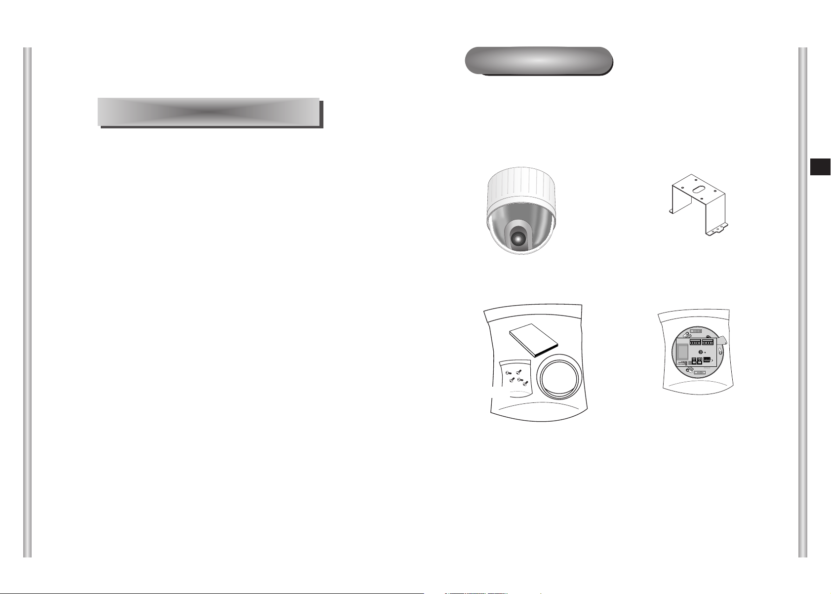
Before Installing
Checking Package Contents
Please check that all components listed below are included in the
package:
In this chapter, we will check the contents of the package before
installing the SCC-643(P), and prepare a power adapter suitable for
the power supply system.
(Power Consumption: 18W; Voltage: 24VAC, 1.5A)
Then, we will install the SCC-643(P) and connect the cables.
Screws
Owner’s
Instructions
Cover Body
SCC-643(P)
E
Bracket anchor
Camera Holder
2-1
2-2
Page 12
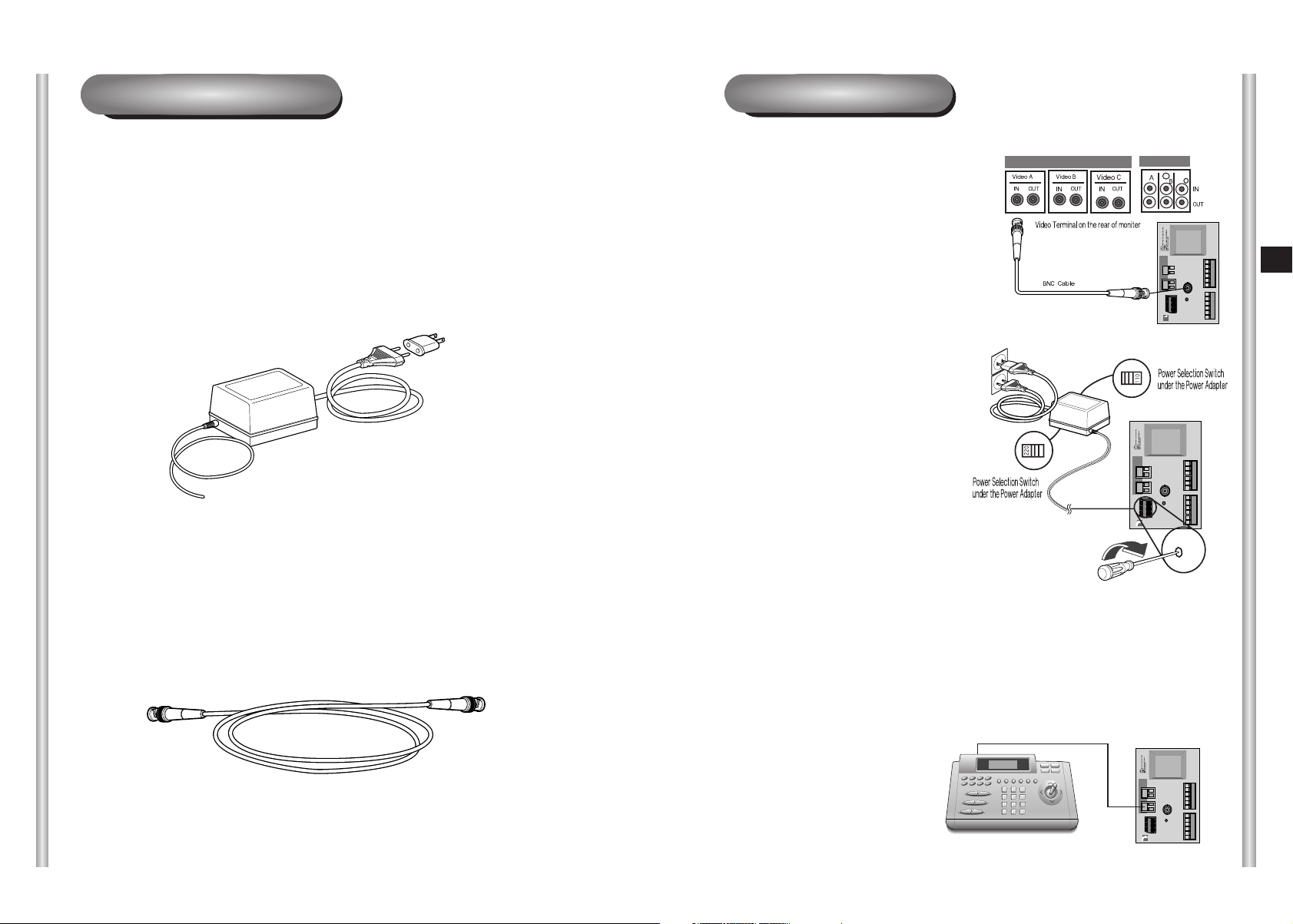
Preparing the Cables
Cable Connection
To install and use the SCC-643(P), the following cables should be
prepared.
Power Adapter Cable
The cable that plugs into the SCC-643(P) power input receptacle has the
rated voltage of 24VAC, 1.5A.
Check the rated voltage before using the cable.
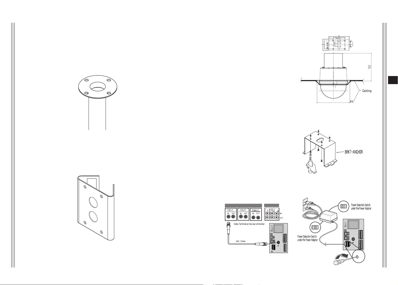
Video Cable
The SCC-643(P)'s cable is a BNC Cable for connecting the video-output
terminal to the video-input terminal of the monitor.
1. First, connect one end of the
BNC video cable connector to
the Video Output Terminal
(VIDEO OUT)
2. Then, connect the other end of
the connector to the Video Input
Terminal of the monitor.
3. Now connect the Power Adapter
Cable. Use a driver to screw
one part of the two lines of
Power Adapter to Power Input
Terminal of the SCC-643(P).
4. Adjust the switch below the Power Adapter to the proper voltage.
Then, connect the Power Adapter's plug to the Power Connector.
E
2-3
5. Connect the Remote Control
Terminal of the SCC-643(P)
and the external Controller.
Controller
Adapter BOARD
2-4
Page 13

Installing SCC-643(P)
Installation Precautions
1) Make sure that the installation site can sufficiently support a minimum of
four times the net weight of the SCC-643(P) SmartDome Camera and
other accessories.
2) Install in an area where the space above the ceiling board is over 18 cm
(7 in.) high.
3) Use the supplied screws to fasten the camera to the bracket assembly.
4) Keep persons away from the installation area, as there is a risk of falling
objects.
Also, move valuables to a safe location before installation.
Separately Sold Products for Installation
Depending on the installation site, it may be convenient to use one of the
following products.
1) CEILING MOUNT BRACKET (SBR-100DCM)
This bracket is used for installing
the SmartDome CAMERA in the
plenum above the drop ceiling.
3) INDOOR HOUSING (SHG-120)
This housing is used for installing the SmartDome Camera to an indoor
wall or a ceiling.
E
4) OUTDOOR HOUSING (SHG-220)
This housing is used for installing the SmartDome Camera to an
outdoor wall or a ceiling.
2) WALL MOUNT ADAPTOR (SADT-100WM)
This adaptor is used for installing the indoor
housing or the outdoor housing for the
SmartDome Camera on a wall.
2-5
2-6
Page 14
5) CEILING MOUNT ADAPTOR (SADT-100CM)
This adaptor is used for installing the indoor housing or the outdoor
housing for the SmartDome Camera to a concrete ceiling.
Installing the Camera
1. [Figure 1] Install the structure on the
ceiling.
(Refer to Installation reference
for the Length of the structure)
* Built in by the builder of the structure
E
6) POLE MOUNT ADAPTOR (SADT-100PM)
This adaptor is used for installing the WALL MOUNT ADAPTOR
(SADT-100WM) to a pole that is over 8 cm (2.76 in.) in diameter.
[Figure 1]
Length of
ceiling Hole
2. Make a hole in the ceiling where the camera will be installed.
(The hole should be about ø185)
3. [Figure 2] Assemble the
BRKT-ANCHOR on the ceiling
and screw the 4 bolts in.
[Figure 2]
4. [Figure 3,4] Connect the various cables to the CAMERA ADAPTER.
(See page 2-4)
2-7
[Figure 3]
[Figure 4]
2-8
Page 15
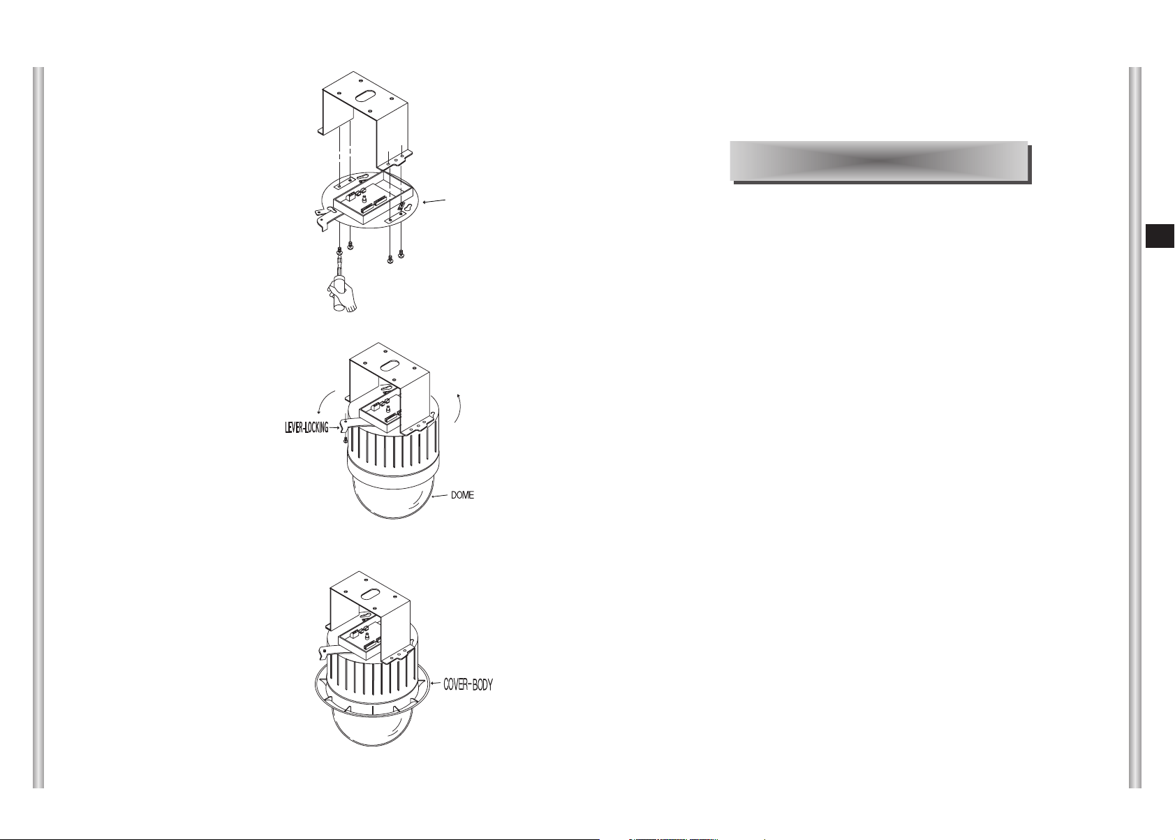
5. [Figure 5] Match the
BRKT-ANCHOR and CAMERA
ADAPTER and use 4screws
(PH M4 x 8) to assemble them.
[Figure 5]
Chapter 3 Setup Menu Overview
CAMERA ADAPTER
6. [Figure 6] Match the 3 holes on
the back of the CAMERA and the
CONNECTOR and turn it left
about 15 degrees.
(Check the sound of LOCKING
and that the LEVER-LOCKING
is in place)
* Use the screws (BH M3 x L8) to
connect the CAMERA and the
ADAPTER so they don't move.
7. [Figure 7] Assemble the
COVER-BODY onto the DOME.
[Figure 6]
15
°
[Figure 7]
In this chapter, we will look over the Setup Menu of the SCC-643(P),
First we'll look over the overall structure of the Setup Menu, and then
we'll look at the functions of each menu.
E
2-9
3-1
Page 16
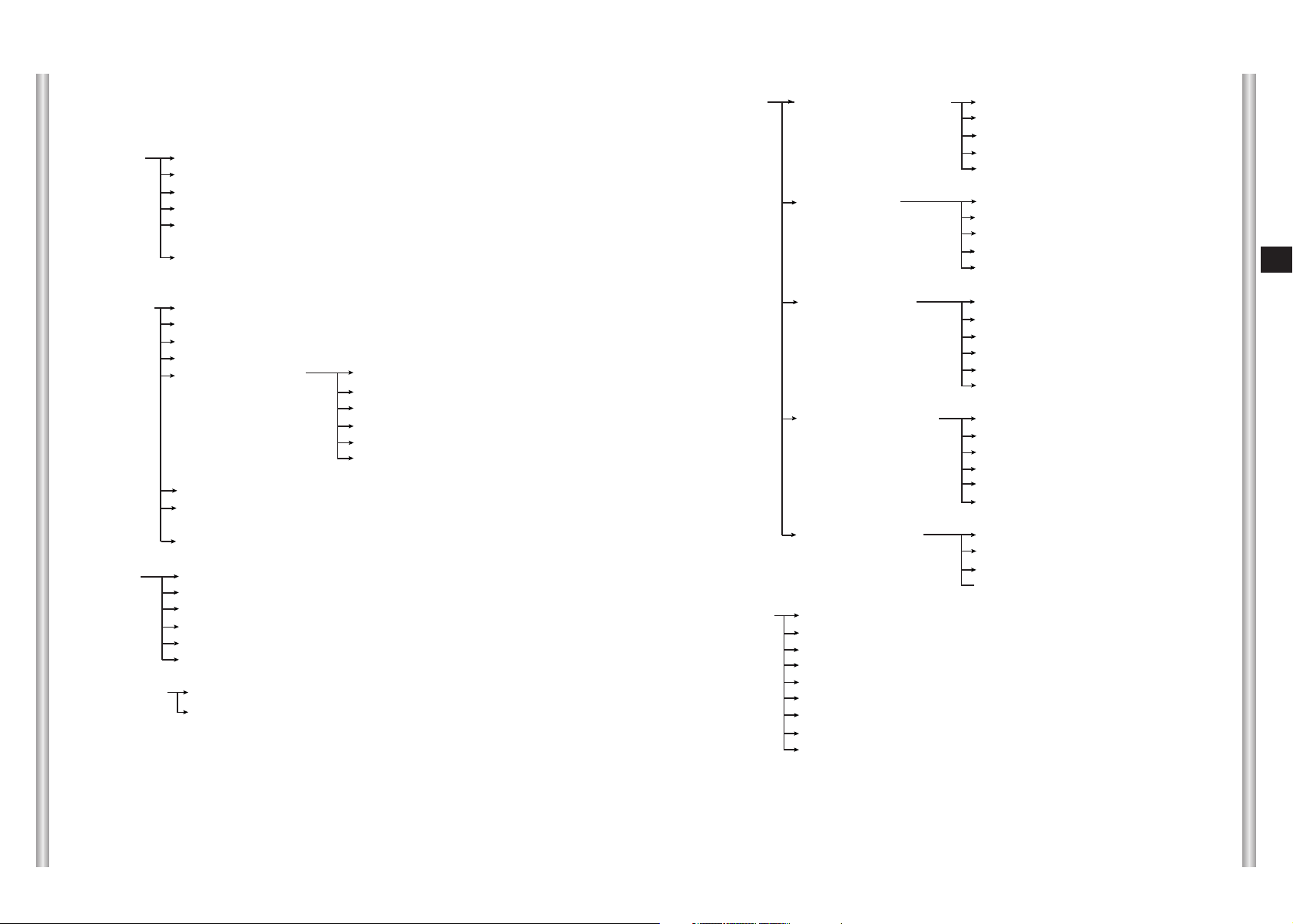
Structure of the Setup Menu
CAMERA CAMERA ID ON.../OFF
V-SYNC INT/LINE...
COLOR/BW COLOR/BW/AUTO...
ZOOM SPEED 1/2/3/4
MOTION DET ON.../OFF
EXIT QUIT/SAVE/PRESET
ALARM SET ALARM PRIORITY SET ALARM1 1~4
ALARM2 1~4
ALARM3 1~4
ALARM4 1~4
EXIT QUIT/SAVE
ALARM IN SET ALARM1 NO/NC/OFF
ALARM2 NO/NC/OFF
ALARM3 NO/NC/OFF
ALARM4 NO/NC/OFF
EXIT QUIT/SAVE
E
VIDEO SET IRIS ALC.../MANU...
SHUTTER OFF/1/100,1/10K/AUTO/FIX
AGC OFF/LOW/HIGH
WHITE BAL ATW/AWC/MANU...
SPECIAL ON.../OFF POSI/NEGA
PIP ON.../OFF
MIRROR ON/OFF
H-DTL
V-DTL
RET
AUTO FOCUS AF/MF/ONEAF
D-ZOOM OFF/ X2 ~ X10
EXIT QUIT/SAVE/PRESET
PRESET POSITION SET ...
VIDEO SET ON.../OFF
PRESET ID ON.../OFF
SCAN ON/OFF
DWELL TIME 1~60S
EXIT QUIT/SAVE/DEL
AUTO MODE AUTO PAN ...
PATTERN SET 1/2/3
+ / -
ALARM OUT SET ALARM1 1~3
ALARM2 1~3
ALARM3 1~3
ALARM4 1~3
MOTION 1~3
EXIT QUIT/SAVE
ALARM PATTERN SET ALARM1 OFF/1~3/HALF1/HALF2/FULL
ALARM2 OFF/1~3/HALF1/HALF2/FULL
ALARM3 OFF/1~3/HALF1/HALF2/FULL
ALARM4 OFF/1~3/HALF1/HALF2/FULL
MOTION OFF/1~3/HALF1/HALF2/FULL
EXIT QUIT/SAVE
AUX OUT CONTROL OUT1 ON/OFF
OUT2 ON/OFF
OUT3 ON/OFF
EXIT QUIT/SAVE
OTHER SET AC OFF/6HOUR/12HOUR/18HOUR/24HOUR
P.P/T ON/OFF
HOME RETURN OFF/1~60MIN/2~12HOUR
HOME POSITION 0~127
AUTO FLIP ON/OFF
PRIVACY ZONE ...
CAM RESET ...
LANGUAGE ENGLISH
EXIT QUIT/SAVE
3-2
The diagram shown above illustrates the overall structure of the Setup
Menu. In this section, a description of the Setup menu features will enable
users of the SCC-643(P) to tailor it to their personal needs.
3-3
Page 17
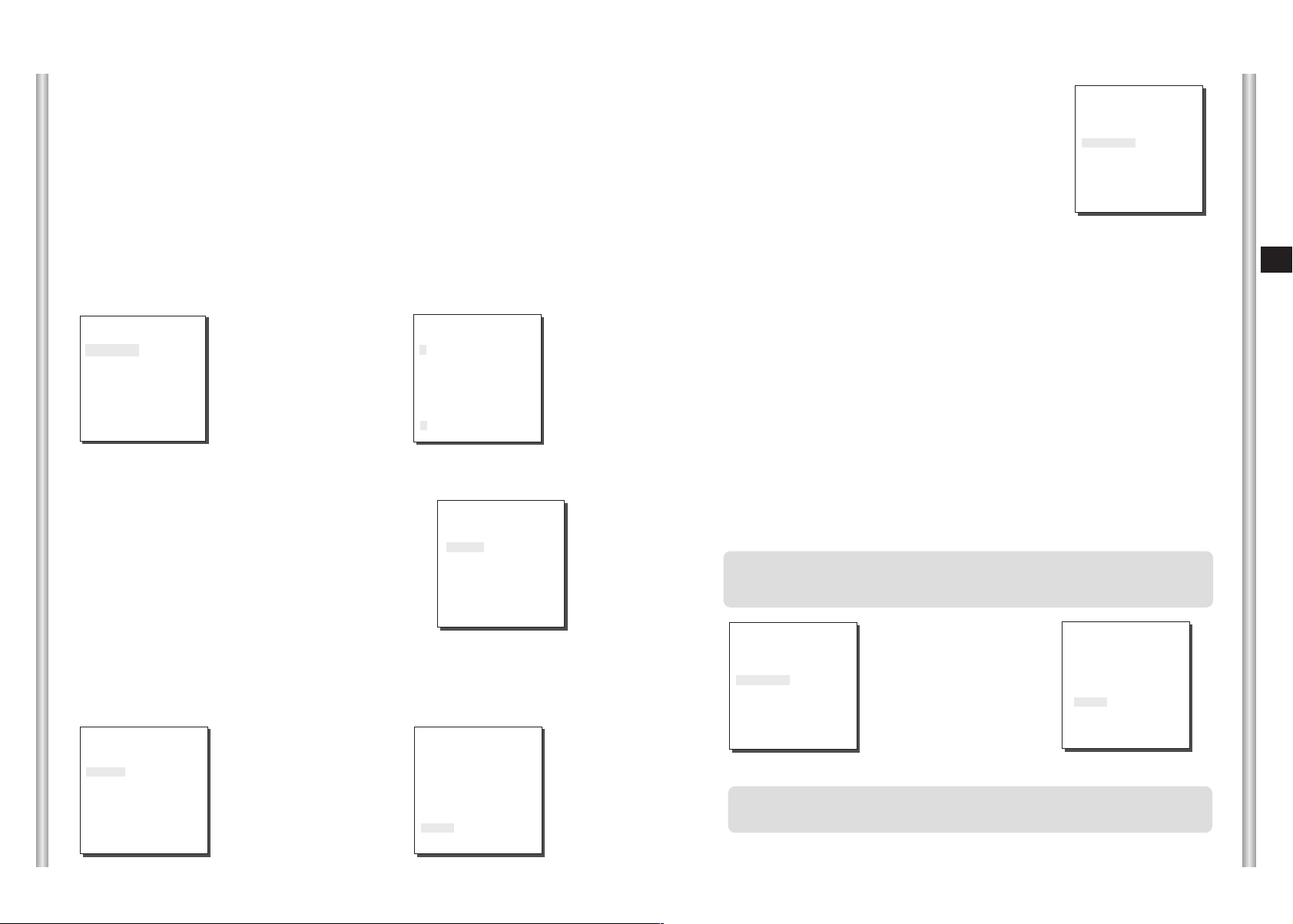
1. CAMERA SET MENU
CAMERA ID
The CAMERA ID menu assigns an ID to the SCC-643(P) to be displayed
on the connected monitor.On the CAMERA SET menu screen, select
CAMERA ID to ON and press [Enter]. You will see the sub screen for
deciding on the ID of the SCC-643(P). The Camera ID can have up to 12
alphanumeric characters, along with several special characters.
The assigned camera ID may be positioned to any desired location on the
screen by using the LOCATION submenu.
(CAMERA SET)
CAMERA ID ON...
V-SYNC INT
COLOR/BW AUTO...
ZOOM SPEED 3
MOTION DET OFF
EXIT QUIT
➜
Press
[Enter]
* " ... " Means there are Sub Menus.
V-SYNC
In the V-SYNC menu, vertical synchronization can
be selected. The vertical synchronization signal
supported by the SCC-643(P) is the INT mode
made by clock inside the SCC-643(P) and LINE
mode adjusting vertical synchronization to the
exterior power frequency.
Select LINE and press [Enter]. You will see the LINE LOCK submenu
where you can adjust the phase of the LINE LOCK.
You can use the PHASE menu of the LINE LOCK submenu to assign as
much PHASE as you want.
(CAMERA SET)
CAMERA ID OFF
V-SYNC LINE...
COLOR/BW AUTO...
ZOOM SPEED 3
MOTION DET OFF
EXIT QUIT
➜
Press
[Enter]
(CAMERA ID)
A B C D E F G H I J K L
M N O PQ R S T U V W X
Y Z 0 1 2 3 4 5 6 7 8 9
: ! - +
SP
LOCATION...
RET
SCC-643.....
(LINE LOCK)
PHASE ( 000) --- RET
✽ ( ) /
ï î
SP
(CAMERA SET)
CAMERA ID OFF
V-SYNC INT
COLOR/BW AUTO...
ZOOM SPEED 3
MOTION DET OFF
EXIT QUIT
I ----
COLOR/BW
In the COLOR/BW menu, you can switch ON or OFF the
IR (infrared) Filter.
In low light conditions, IR Filter is turned OFF to the BW
Mode and the sensitivity to low light increases to that of a
black and white camera. In bright light conditions, the IR
Filter is turned ON to the COLOR Mode, and the screen
changes to normal as the sensitivity decreases.
(CAMERA SET)
CAMERA ID OFF
V-SYNC INT
COLOR/BW AUTO...
ZOOM SPEED 3
MOTION DET OFF
EXIT QUIT
COLOR : The IR Filter is ON and the screen is normal.
BW : The IR Filter is OFF and the screen is black and white.
(Sensitivity to low light is increased to a level comparable to a black and white
camera.)
AUTO : Select to automatically switch between the COLOR mode and BW mode
depending on the amount of light. In low light conditions, the IR Filter is turned OFF
and the sensitivity to low light is increased by switching to the BW mode, but in
bright light conditions, the IR Filter is turned ON and the sensitivity is decreased by
switching to the COLOR mode. If you select AUTO and press the ENTER button, a
screen from which you can set the BURST ON / OFF, BW LEVEL and DWELL
TIME will appear.
- BURST ON : The color burst signal is output together with black and white
composite video signal.
- BURST OFF : The color burst signal is not output.
- LEVEL : You can set the brightness level that changes from COLOR mode to BW
mode in 3 steps : LOW, MEDIUM, and HIGH.
- DWELL TIME : Set the HOLDING time for switching between COLOR and BW
mode depending the changes in the amount of light. You can set the HOLDING
time to 10sec (S), 30sec, 60sec, or 300sec( L).
In AUTO mode, if shutter is selected as off or 1/100~1/10K, AGC will
operates in high speed mode, and you cannot change it manually, as it is
indicated by "---".
(CAMERA SET)
CAMERA ID OFF
V-SYNC INT
COLOR/BW AUTO...
ZOOM SPEED 3
MOTION DET OFF
EXIT QUIT
➜
Press
[Enter]
(BW SETUP)
BURST ON
LEVEL MEDIUM
DWELL TIME S--|----L
RET
Caution : If you use an infrared light source while in AUTO mode, AUTO
switching malfunction and camera AF malfunction may occur.
E
3-4
3-5
Page 18

ZOOM SPEED
In the ZOOM SPEED menu you can
select the speed of the ZOOM Key
(Tele/Wide).
Use the [Left] or [Right] keys in the
ZOOM SPEED menu to select
the speed.
(CAMERA SET)
CAMERA ID OFF
V-SYNC INT
COLOR/BW AUTO...
ZOOM SPEED 3
MOTION DET OFF
EXIT QUIT
1 : Magnification x 22 takes about 18 seconds. Slowest speed
2 : Magnification x 22 takes about 10 seconds. Low speed
3 : Magnification x 22 takes about 6 seconds. High speed
4 : Magnification x 22 takes about 4 seconds. Fastest speed
If you press [ENTER] once more, you will exit the "AREA" setting menu.Use
the "SENSITIVITY" menu to set the sensitivity of the MOTION Detection.The
Higher it is set, the more sensitive the Motion Detection moves.
➜
Use the [Left, Right, Up, Down] Keys
Press the [5] key to assign an area
or to cancel the area.
E
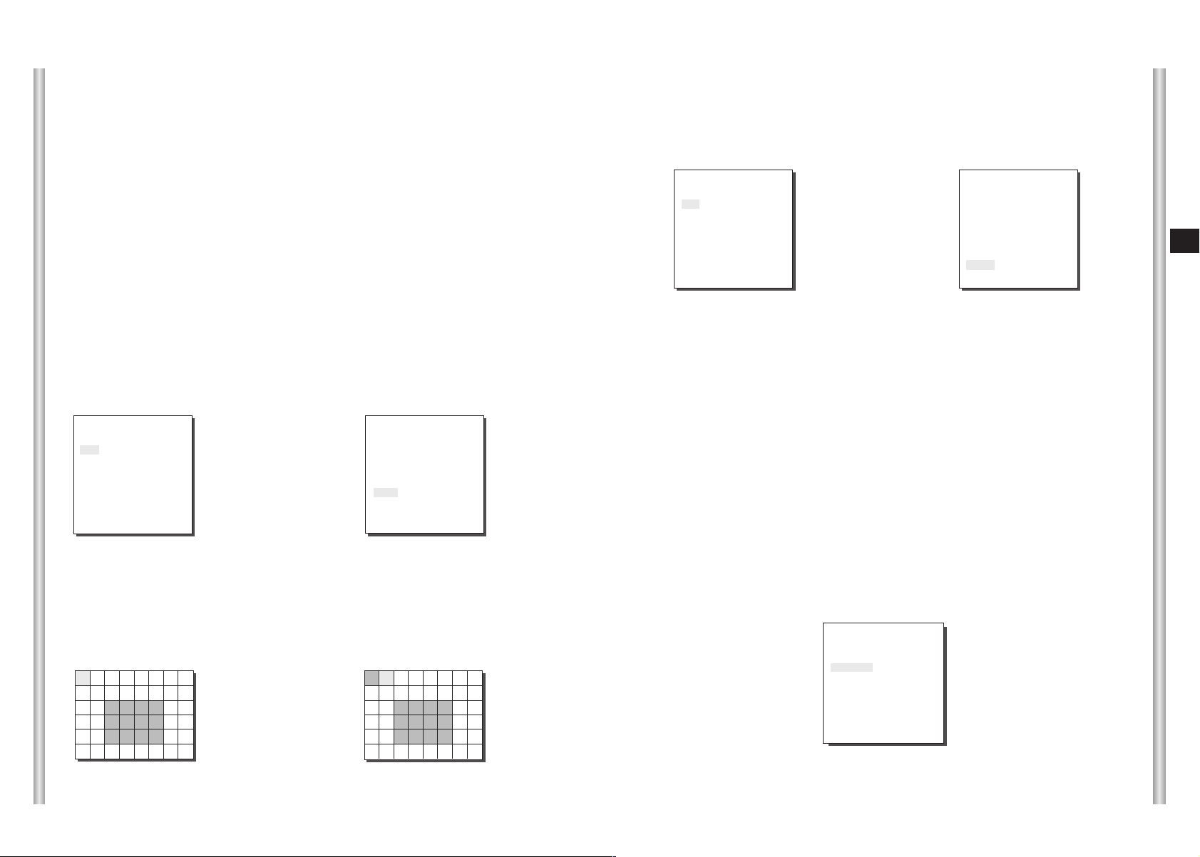
MOTION DET
In MOTION DET, you can set the Motion Detection function, Motion Detection
Sensitivity, and the Area of Motion Detection. If the Motion Detection function
is set, the movement of an intruder can be detected. When motion is detected,
it sets off the Alarm signal of the Controller.
(CAMERA SET)
CAMERA ID OFF
V-SYNC INT
COLOR/BW AUTO...
ZOOM SPEED 3
MOTION DET ON...
EXIT QUIT
➜
Press
[Enter]
If you select ON and press the [ENTER] key, the “MOTION DET” submenu
screen will come up.
The “AREA” menu, from which you can specify screen areas where the Motion
Detection function will be applied, can be set to either PRESET or USER. If
you set the “AREA” menu to PRESET, the Motion Detection function will be
applied to the areas preset as factory defaults.
If you set the AREA menu to USER and press the [ENTER] key, you can
choose from 48 areas where you want to apply the Motion Detection function.
Use the [5] key and [left, right, up, down] keys to move and select the motion
detection area.
Press the [5] key to assign an area or to cancel the area.
(MOTION DET)
AREA PRESET...
SENSITIVITY MEDIUM
RET
*Motion Detection function does not operate while handling slow SHUTTER, PRESET,
SCAN, AUTO MODE(AUTO PAN, PATTERN) or MANUAL KEY (JOYSTICK, ZOOM, FOCUS, IRIS).
EXIT
The EXIT menu is used to quit the CAMERA SET
menu of the SCC-643(P) and return to the MAIN
MENU.
- QUIT: Ignores the changed information and
restores the saved information.
- SAVE: Saves the information of the setting
condition of the menu.
- PRESET: Ignores the changed information and
restores the initial factory defaults of
the menu.
(CAMERA SET)
CAMERA ID OFF
V-SYNC INT
COLOR/BW AUTO...
ZOOM SPEED 3
MOTION DET OFF
EXIT QUIT
2. VIDEO SET MENU
IRIS
The video output level of the monitor can be controlled by the IRIS lens
depending on the level of the incoming light.The video output level can be
set in the ALC menu.The opening and shutting of the Iris lens can be set
manually in the MANU menu.
3-6
3-7
Page 19
ALC
Choose the ALC of the IRIS item and press [ENTER] and set he submenu to
the Video Output level and BLC will be shown.The Video Output Level can
be set in the level item using the [Left, Right] keys.
MANU
If the IRIS item is set to MANU, the sub screen to open and shut the Iris
manually will be shown. Using the [Left, Right] keys in the LEVEL item
you can set Iris manual setting.
BLC (Submenu of the ALC menu)
With conventional cameras, strong background lighting interferes with the
clarity of objects, making them appear dark. In the SCC-643(P), setting the
BLC (Back Light Compensation), submenu of ALC/MANU menu, will solve
the problem of backlight and give you a clear screen.
Set the BLC menu to ON and the Back Light Compensation function will be
applied to the screen areas of AREA menu.The screen area where Back
Light Compensation should be applied can be set with the PRESET or
USER item.If the AREA menu is set to PRESET, the backlight compensation
function is applied to the factory defaults of the SCC-643(P).
If the AREA menu is set to USER and [ENTER] is pressed, the user can
select the applied area of the backlight compensation function.
(VIDEO SET)
IRIS ALC...
SHUTTER
MOTION
WHITE BAL ATW
SPECIAL OFF
AUTO FOCUS ONEAF
D-ZOOM OFF
EXIT QUIT
AUTO x 4
NORMAL
➜
Press
[Enter]
(ALC)
AREA PRESET...
BLC OFF
LEVEL (0) --- RET
I ----
Use the [left, right, up, down] keys to move to the area you want.
Press the [5] key to assign an area or to cancel the area.
Press the [ENTER] key again to exit the “AREA” setup menu.
➜
Use the
[Left, Right, Up, Down] Keys
(VIDEO SET)
IRIS MANU...
SHUTTER
MOTION
WHITE BAL ATW
SPECIAL OFF
AUTO FOCUS ONEAF
D-ZOOM OFF
EXIT QUIT
AUTOx4
NORMAL
➜
Press
[Enter]
(MANUAL)
LEVEL ( 00) --- RET
I ----
SHUTTER
In the SHUTTER menu, the high-speed Electric shutter and AUTO low speed
shutter of the SCC-643(P) and the FIX low speed shutter can be set.
The High speed Electric Shutter supports 7 different speeds from 1/100 to
1/10K of a second. The AUTO low speed shutter and FIX low speed shutter
supports 12 different speeds from 2x to 128x magnifications.
The Low speed shutter is the function that sets the shutter speed to low in
order to clearly see the object filmed in low light. To automatically slow down
the speed of the shutter by sensing the brightness of the light, set to AUTO
low speed shutter, and If the user wants to manually set the speed of low
speed shutter, set it to FIX. The number after the AUTO and FIX are the
number of the fields stored.
Large number of fields decreases shutter speed and results in brighter
screen.
However, dragging effect occurs when the subject is in motion.
(VIDEO SET)
IRIS ALC...
SHUTTER
MOTION
WHITE BAL ATW
SPECIAL OFF
AUTO FOCUS ONEAF
D-ZOOM OFF
EXIT QUIT
AUTOx4
NORMAL
E
3-8
3-9
Page 20

SLOW
If your press the left/right keys continuously, the speed will appear in the
following order.
Order
OFF ➞ 1/100(1/120) ➞ 1/250 ➞ 1/500 ➞ 1/1000 ➞ 1/2000 ➞
1/4000 ➞ 1/10K ➞ OFF ➞ AUTOX2 ➞ AUTOX4 ➞ AUTOX6 ➞
AUTOX8 ➞ AUTOX12 ➞ AUTOX16 ➞ AUTOX24 ➞ AUTOX32 ➞
AUTOX48 ➞ AUTOX64 ➞ AUTOX96 ➞ AUTOX128 ➞ OFF ➞
FIX X2 ➞ FIX X4 ➞ FIX X6 ➞ FIX X8 ➞ FIX X12 ➞ FIX X16 ➞
FIX X24 ➞ FIX X32 ➞ FIX X48 ➞ FIX X64 ➞ FIX X96 ➞ FIX X128
AGC
In the AGC menu, you can specify whether to automatically control the
GAIN when the obtained video is below a certain level of brightness.
To automatically control the GAIN, set the AGC menu to LOW/HIGH.
Otherwise, set it to OFF.
If the you set the AGC to LOW, the maximum GAIN of the AGC will be set
to low, and if set to HIGH, the maximum GAIN will be set to high.
Under low light conditions, SHUTTER Mode change from AGC to
MOTION (AUTO Mode). In the MOTION, use the [left, right] keys to select
"S.S/SLOW/NORMAL/FAST/F.F".
(VIDEO SET)
IRIS ALC...
SHUTTER OFF
AGC
WHITE BAL ATW
SPECIAL OFF
AUTO FOCUS ONEAF
D-ZOOM OFF
EXIT QUIT
LOW
This enhances the resolution of a still image by selecting a low value for
AGC GAIN and a slow speed for SHUTTER SPEED.
(This is used mainly to monitor inanimate objects in dark places.)
NORMAL
This shows the normal picture by selecting a medium value for AGC GAIN
and the normal speed for SHUTTER SPEED.
(This is used mainly to monitor moving objects in dark places.)
FAST
This focuses on the moving object by selecting a high value for AGC
GAIN and a high speed for SHUTTER SPEED.
(This is used mainly to monitor objects moving conspicuously in dark
places.)
F.F
This focuses on the fastest moving object by selecting the highest value
for AGC GAIN and the fastest speed for SHUTTER SPEED.
(This is used mainly to monitor fast moving objects in dark places.)
E
S.S
This maximally enhances the resolution of a still image by selecting the
lowest value for AGC GAIN and the slowest speed for SHUTTER SPEED.
(This is used mainly to monitor inanimate objects in dark places.)
3-10
3-11
Page 21
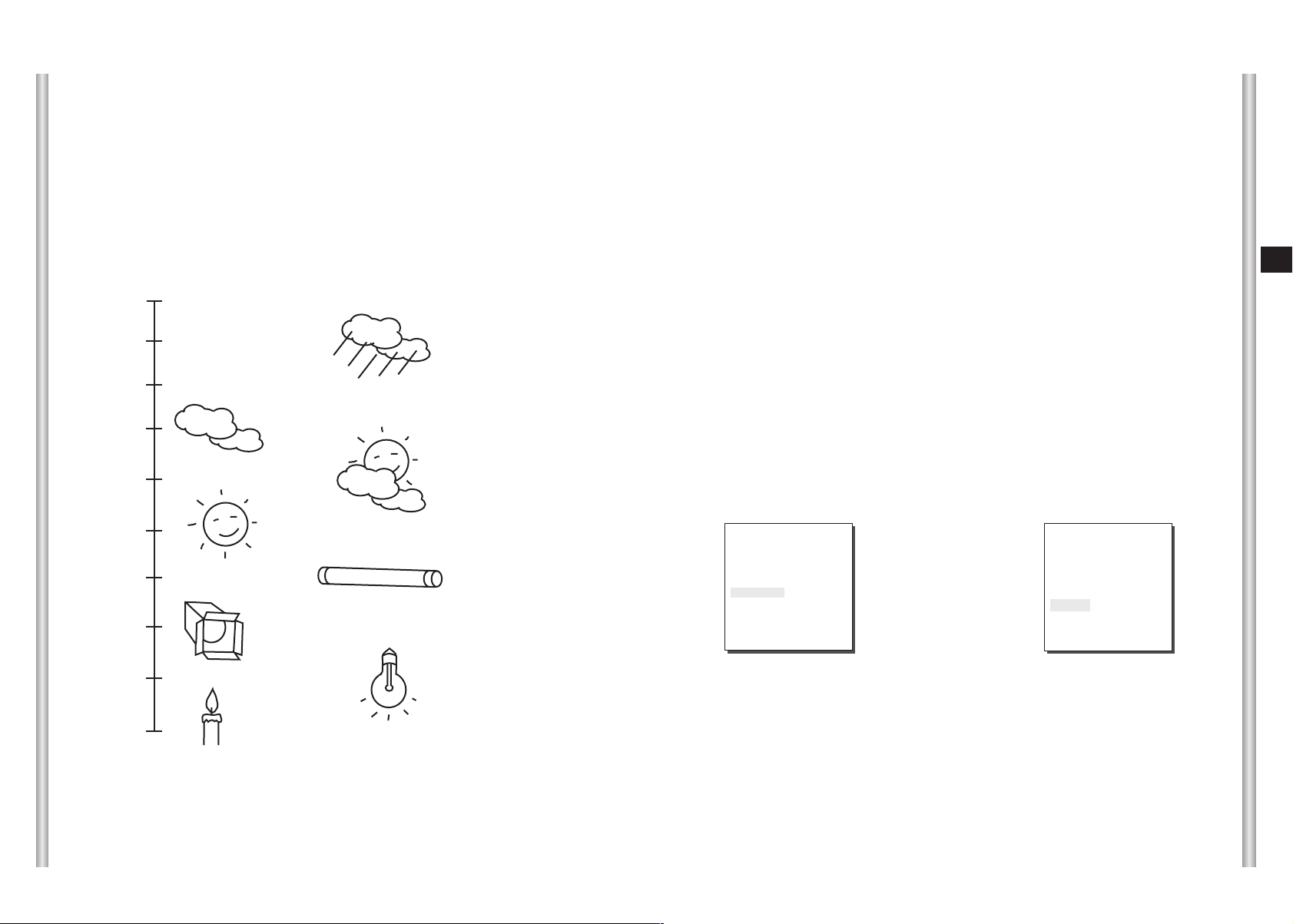
WHITE BAL
Lights are generally denoted as color temperatures and expressed in
°K
°K
°K
°K
°K
°K
) units.
Blue sky
Rainy
Cloudy
Partly Cloudy
Kelvin (
The general light color temperatures are shown below.
10000
9000
8000
7000
6000
WHITE BAL
The WHITE BAL menu insures that white is calibrated normally under any
color temperature condition.
●
When the WHITE BAL menu is set to the ATW mode, the white balance
is automatically specified according to the color temperature.
●
In the case of setting the WHITE BAL menu to AWC mode, pressing
[ENTER] while having a white paper in front of the Camera will
automatically set the white balance in accordance with the color
temperature only one time.
●
If WHITE BAL menu is set to MANU mode, the user can set the white
Balance considering the current illumination. Select MANU item and
press [ENTER], the sub screen where you can select Manual White
Balance will be shown. Use the left/right keys to select 3200°K, 5600°Kor
OFF(USER) mode in the PRESET menu.
°K
- 3200
: Set color temperature to 3200
- 5600°K: Set color temperature to 5600
- OFF(User) : Set the appropriate value in the RED and BULE graph.
°K
°K
E
3-12
5000
4000
3000
2000
1000
°K
°K
°K
°K
°K
Sunny
Halogen lamp
Candlelight
Fluorescent lamp
Tungsten lamp
(VIDEO SET)
IRIS ALC...
SHUTTER
MOTION
WHITE BAL MANU...
SPECIAL OFF
AUTO FOCUS ONEAF
D-ZOOM OFF
EXIT QUIT
AUTOx4
NORMAL
➜
Press
[Enter]
(AWB/MANU)
PRESET OFF(USER)..
RED (00) - ---I ----
BLUE (00) --- RET
I ----
3-13
Page 22
SPECIAL
In the SPECIAL menu, POSI/NEGA, PIP, Mirror, and vertical and
horizontal detail level can be adjusted.
- POSI/NEGA: Video output signal is outputted normal/reverse.
- PIP(Picture in Picture): When Digital Zoom is activated, the 1/16
minimized screen will be shown.
- MIRROR: Reverse the video output signal
- H-DTL: Adjust Horizontal Detail Level.
- V-DTL: Adjust Vertical Detail Level.
Select ON and press [ENTER], the "SPECIAL" submenu to choose the
special functions will be shown.
horizontally.
AUTO FOCUS
In the AUTO FOCUS MENU, the Focus method can be set to AF, MF, or ONEAF.
- AF: With AUTO FOCUS MODE, you can monitor the screen continuously and it
will focus automatically. While moving the zoom keys, it will automatically
focus so FOCUS key input is not necessary.
- MF: In MANUAL FOCUS MODE the user adjusts the Focus manually.
- ONEAF : The ONEAF Mode performs Auto-focusing only when the SCC-643(P)
stops after moving and when the SCC-643(P) is not moving it is same
as MF mode.
(The ONEAF Mode does not work when zooming out.
❈
When in the MF/ONEAF Mode, press the NEAR and FAR keys on the
Controller (SSC-1000) at the same time to perform AUTO FOCUS.)
Use the left/right keys to select AF, MF or ONEAF in the AUTO FOCUS menu.
E
(VIDEO SET)
IRIS ALC...
SHUTTER
MOTION
WHITE BAL ATW
SPECIAL ON...
AUTO FOCUS ONEAF
D-ZOOM OFF
EXIT QUIT
AUTOx4
NORMAL
➜
Press
[Enter]
(SPECIAL)
POSI/NEGA +
PIP OFF
MIRROR OFF
H-DTL (0) --- -I ---V-DTL (0) --- I -----
RET
To choose functions use the left/right keys to select an item.In the PIP
menu, select ON and press [ENTER]. Use the [left, right, up, down]
keys to set the location of the PIP.
❈
The PIP function does not work in the slow-speed Shutter Mode and Privacy
Zone Display Mode, and the Mirror function does not work in the PIP window.
❈
The Mirror function does not work if Privacy Zone is set.
(SPECIAL)
➜
Press
[Enter]
3-14
POSI/NEGA +
PIP ON...
MIRROR OFF
H-DTL (0) -- -- I ---V-DTL (0) ----I ---RET
PIP Screen
(VIDEO SET)
IRIS ALC...
SHUTTER
MOTION
WHITE BAL ATW
SPECIAL OFF
AUTO FOCUS ONEAF
D-ZOOM OFF
EXIT QUIT
AUTOx4
NORMAL
D-ZOOM
In the D-ZOOM menu, you can choose the Digital Zoom magnification.
You can select a magnification from OFF to 10 times.
When Digital Zoom is selected at 10 times, the camera can show upto
220 times because the Optical Zoom is 22 times.
Use the [left, right] keys to select the magnification in the D-ZOOM menu.
(VIDEO SET)
IRIS ALC...
SHUTTER
MOTION
WHITE BAL ATW
SPECIAL OFF
AUTO FOCUS ONEAF
D-ZOOM OFF
EXIT QUIT
AUTOx4
NORMAL
(VIDEO SET)
IRIS ALC...
SHUTTER
MOTION
WHITE BAL ATW
SPECIAL OFF
AUTO FOCUS ONEAF
D-ZOOM X10
EXIT QUIT
AUTOx4
NORMAL
EXIT
It's the same as the EXIT function of the CAMERA SET menu.
3-15
Page 23
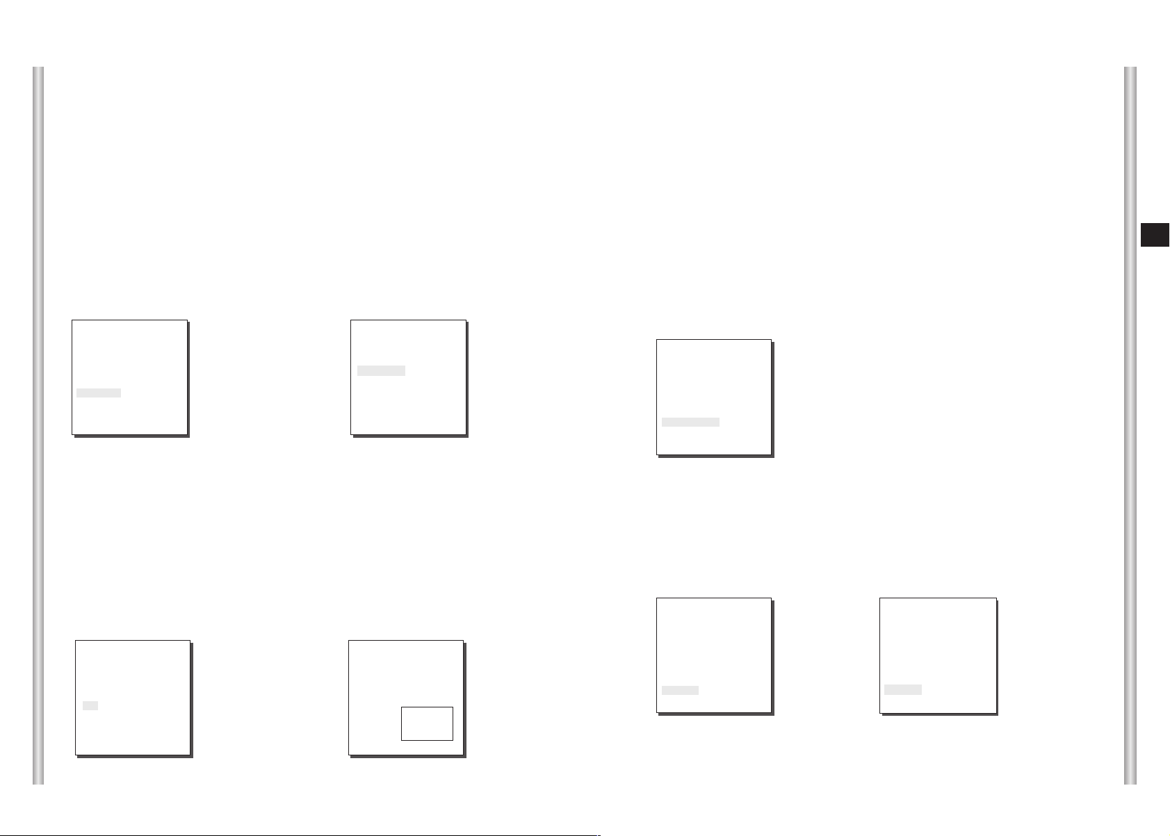
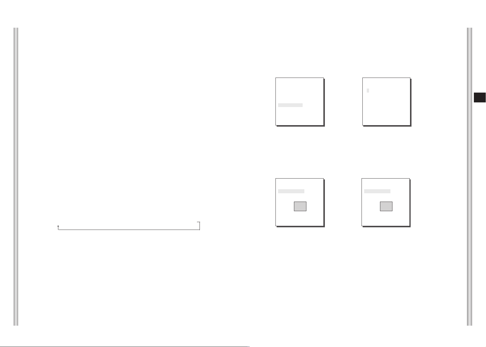
3. PRESET
This is the menu that user sets the PAN/TILT location, Zoom/Focus, and
screen condition, so the camera can monitor the presetting area on
demand. A total of 128 presets are available.
Among the 128 PRESETS HOME POSITION, PRESET 1: ALARM1,
PRESET 2: ALARM2, PRESET 3: ALARM3, PRESET 4:
ALARM4,PRESET 5: set as special preset corresponding MOTION.
POSITION SET...
From "POSITION SET..." press [ENTER] to get
into the PAN/TILT, FOCUS/ZOOM SET screen
to set the PAN/TILT location and FOCUS/ZOOM
condition then press [ENTER] to return to a
higher menu.
VIDEO SET
This is the screen setting function for each PRESET.
Refer to the explanation under "VIDEO SET menu".
PRESET NO.0
SET PAN/TILT
SET ZOOM/FOCUS
E
* * MAIN MENU * *
CAMERA...
VIDEO SET...
PRESET...
AUTO MODE...
ALARM SET...
OTHER SET...
➜
Press
[Enter]
➜
Press
[Enter]
PRESET NO.0
POSITION SET...
VIDEO SET OFF
PRESET ID ON...
SCAN ON
DWELL TIME 2 S
EXIT QUIT
(PRESET MAP)
0 H 1 2 3 4
5 6 7 8 9
10 11 12 13 14
15 16 17 18 19
20 21 22 23 24
25 26 27 28 29
î ï
30 31
ID:PRESET 0
RET
❈ " ... " Means there are Sub Menus.
PRESET ID
This is the ID set up function for each PRESET.
It can be set up to 12 characters using the left,
right, up, and down keys.
The ID location can be set in the submenu of
"LOCATION..."
SCAN
This function sets up for movement or no
movement in "SCAN" motion.
PRESET NO.0 ID
A B C D E F G H I J K L
M N O PQ R S T U V W X
Y Z 0 1 2 3 4 5 6 7 8 9
: ! - + * ( ) /
SP
ï î
SP
LOCATION...
RET
PRESET 0....
PRESET NO.0
POSITION SET...
VIDEO SET... ON...
PRESET ID ON...
SCAN ON
DWELL TIME 2 S
When it's PRESET to "ON" it includes SCAN
motion and to "OFF" no movement.
EXIT QUIT
DWELL TIME
This is a function setting for the DWELL TIME of the PRESET location in
"SCAN" motion. It can set DWELL TIME From 1 ~ 60 Sec.
EXIT
"QUIT": Does not save the selected information and returns to a higher
menu.
"SAVE": Do saves the selected information and returns to a higher menu.
"DEL" : Deletes the selected information and restores the DEFAULT.
Then returns to a higher menu.
3-16
3-17
Page 24
4. AUTO MODE
AUTO PAN and PATTERN functions are in AUTO MODE.
AUTO PAN
After selecting the locations of two points (PAN/TILT) of START and
END, it loops continuously in the set up SPEED.
DIRECTION
This sets up the movement direction of the START to END location
(PAN location standard)
"RIGHT " : "LEFT " :
* * MAIN MENU * *
CAMERA...
VIDEO SET...
PRESET...
AUTO MODE...
ALARM SET...
OTHER SET...
➜
Press
[Enter]
➜
Press
[Enter]
START SET
From "START SET...", get into the START
SET setup screen by pressing [ENTER].
After selecting the locations of PAN/TILT
location, press [ENTER] again to return to
higher menu.
END SET
From "END SET...", get into the END SET
setup screen by pressing [ENTER]. Adjust
PAN/TILT location and press [ENTER] to
return to a higher menu.
(AUTO MODE)
AUTO PAN ...
PATTERN SET 1...
RET
AUTO PAN
START SET ...
END SET ...
DIRECTION RIGHT
ENDLESS ON
SPEED STEP5
DWELL TIME 2 S
EXIT QUIT
SET START!
SET END!
ENDLESS
This is a 360-degree rotation function that stops for the DWELL TIME only in
the START and END positions without running between the START and END
positions. It can be set to "ON" or "OFF".
SPEED
This is a setting function for movement speed setup. It can be set from
STEP1 to STEP64.
DWELL TIME
This is a function for setting up the time to stay in the START to END position.
PATTERN
This is a replay function so that the MANUAL functions such as PAN,
TILT, ZOOM, and FOCUS are played for 30 seconds.
* * MAIN MENU * *
CAMERA...
VIDEO SET...
PRESET...
AUTO MODE...
ALARM SET...
OTHER SET...
➜
Press
[Enter]
(SCAN MODE)
AUTO PAN ...
PATTERN SET 1...
RET
PATTERN1 SET
➜
Press
[Enter]
E
3-18
3-19
Page 25
PATTERN can be set upto 3. Choose 1, 2, or 3 with the left or right key in the
"PATTERN SET" and press [ENTER] to get into the PATTERN set up screen.
From the moment "PATTERN 1 SET" is gone for 30 seconds, it memorizes the
MANUAL movements and after 30 seconds it will return to a higher menu. If you
want to finish set up before the 30-second ends, press [ENTER].
5. ALARM SET
ALARM OUT
Each ALARM input corresponds to one of the
3 ALARM OUT.
ALARM OUT
ALARM1 1
ALARM2 2
ALARM3 3
ALARM4 2
MOTION 1
EXIT QUIT
It consists of 4 ALARM INPUTs and 3 ALARM OUTs.It can sense an
ALARM input from exterior SENSORs and it performs with PRESET or
PATTERN function and outputs the ALARM OUT signals.
It recognizes the ALARM signal input as an ALARM signal when it
continues more than 150ms for a time and each ALARM movement time
is decided depending on it's correspondence to the DWELL TIME of the
PRESET and PATTERN connected.
* * MAIN MENU * *
CAMERA...
VIDEO SET...
PRESET...
AUTO MODE...
ALARM SET...
OTHER SET...
➜
Press
[Enter]
( ALARM SET)
ALARM PRIORITY SET..
ALARM IN SET..
ALARM OUT SET..
ALARM PATTERN SET..
AUX OUT CONTROL..
RET
ALARM PRIORITY SET
This sets the priority of the 4 ALARM inputs so
ALARM can work corresponding to the priority.
The priority of the DEFAULT is ALARM1: 1,
ALARM2: 2, ALARM3: 3, ALARM4: 4, MOTION: 5.
If the ALARM is working at the same time and the
priority is the same, it will operate according to the
DEFAULT priority. While the ALARM is working,
it cannot detect MOTION.
ALARM IN SET
This sets the input TYPE to "NO" (Normal Open),
"NC" (Normal Close), or "OFF" depending on the
features of the SENSOR connected.
ALARM PRIORITY
ALARM1 1
ALARM2 2
ALARM3 3
ALARM4 4
EXIT QUIT
ALARM IN
ALARM1 NO
ALARM2 NC
ALARM3 NO
ALARM4 NC
EXIT QUIT
ALARM PATTERN
This sets the operation of PATTERN movements
when inputting ALARM.
When the ALARM is working, it will stay in the
PRESET location corresponding the ALARM for
the DWELL TIME and the ALARM connected to
the PATTERN will continuously operate the
PATTERN movements.
When the ALARM is inputted the correspondence
ALARM PATTERN
ALARM1 OFF
ALARM2 OFF
ALARM3 1
ALARM4 2
MOTION 3
EXIT QUIT
will be as follows: ALARM1 input to PRESET 1,
ALARM 2 input to PRESET 2, ALARM3 input to
PRESET 3, ALARM 4 input to PRESET 4, and
MOTION input to PRESET 5.
The OFF in the Setup Menu does not operate the PATTERN, and it
means 1 ➞ PATTERN1, 2 ➞ PATTERN 2, 3 ➞ PATTERN 3, HALF1 ➞
continuous motion of PATTERN 1 + PATTERN 2, HALF 2 ➞ continuous
motion of PATTERN 2 + PATTERN 3 and FULL ➞ continuous motion of
PATTERN 1+PATTERN2+PATTERN3.
AUX OUT CONTROL
This sets the ALARM OUT motion to continue
or act only when the ALARM is working.
If it is set to OFF the ALARM OUT motion will
operate only when the ALARM is working.
(Active "Low"), and if it's set to ON, the
ALARM OUT will always operate regardless
of the ALARM.
AUX OUT CONTROL
OUT1 OFF
OUT2 OFF
OUT3 ON
EXIT QUIT
E
3-20
3-21
Page 26
6. OTHER SET
AC(Auto Calibration)
This function turns on or off Auto Calibration. SCC-C643(P) has the Auto
Calibration function to improve the precision of LENS and PAN/TILT
motor. You may set to OFF/6HOUR/12HOUR/18HOUR/24HOUR.
Without user’s key input for the time designated by the user, A.C. will
appear on the screen while initializing LENS and PAN/TILT.
P.P/T(Proportional Pan/Tilt)
This function controls the PAN/TILT speed to the ZOOM magnification
ratio during the manual operation of PAN/TILT. If you set
PROPORTIONAL P/T to ON, the PAN/TILT speed will increase in the
ZOOM WIDE mode and decrease in the ZOOM TELE mode even in the
same manual operation.
HOME RETURN
When there is no KEY input or other movement for a certain time, the
camera moves to the HOME location automatically. The HOME location
can be assigned from the HOME POSITION menu.
SET UP TIME FOR HOME RETURN:
OFF: HOME RETURN function cancellation
OFF ➞ 1 MIN ➞ 2 MIN ➞ 3 MIN ~ 60MIN ➞ 2HOUR ~12HOUR
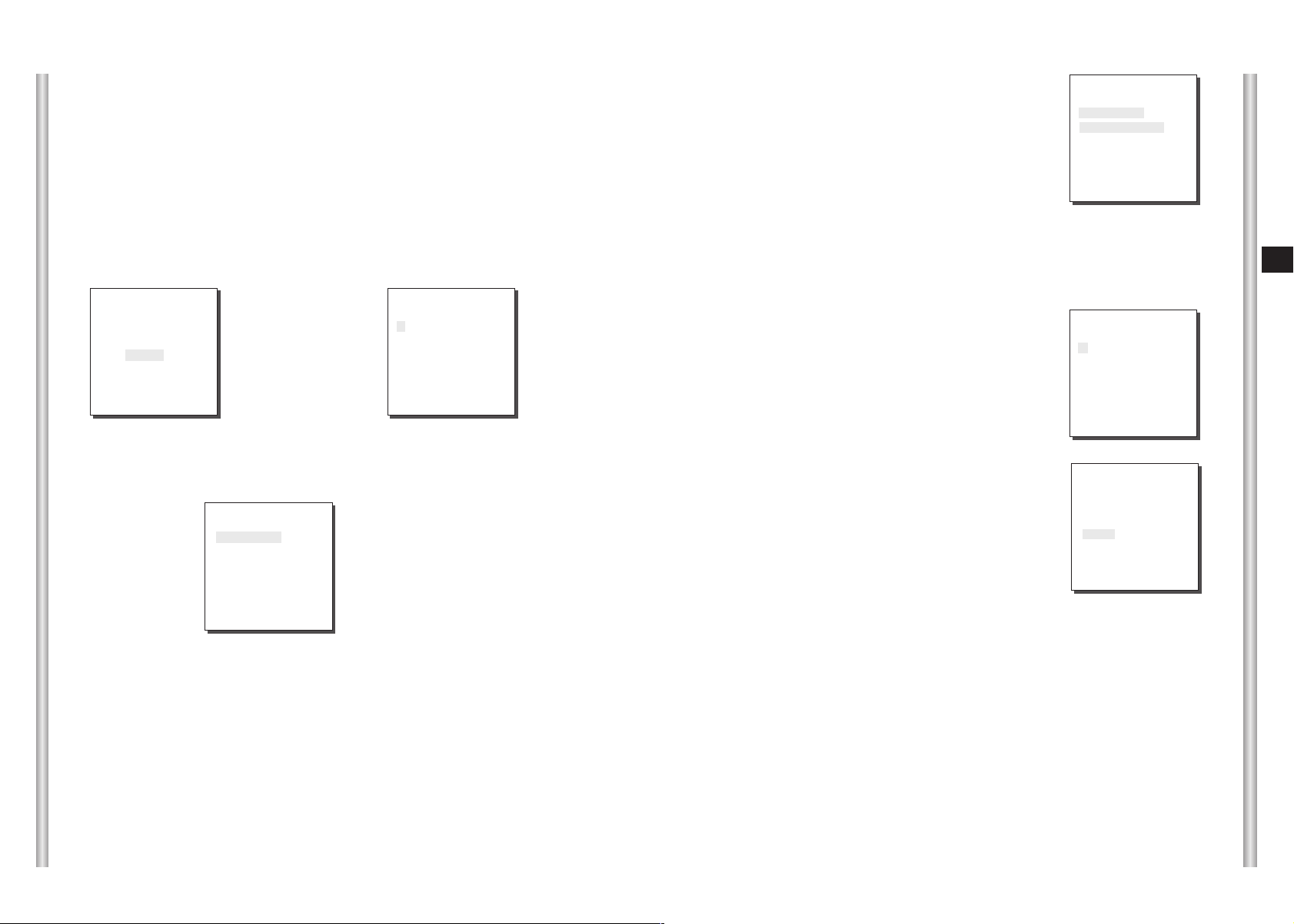
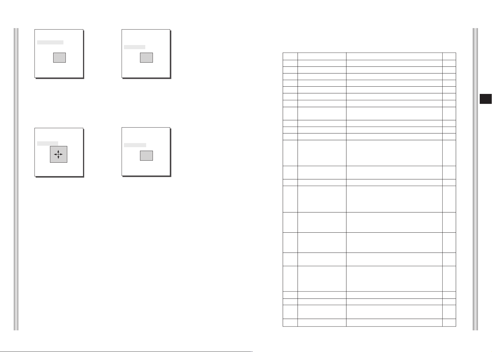
PRIVACY ZONE
Pan/Tilt position and the size of Masking area can be set for up to 8
privacy zones. When shooting the areas where privacy zones are set, the
relevant areas will be concealed from view to protect privacy.
Privacy Zones can be set as follows:
(OTHER SET)
AC OFF
P.P/T ON
HOME RETURN 12HOUR
HOME POSITION 0
PRIVACY ZONE ...
CAM RESET ...
LANGUAGE ENGLISH
EXIT QUIT
➜
[Enter]
KEY
Select PRIVACY ZONE and press the [Enter] key. The PRIVACY ZONE Map
appears and an asterisk "*" is placed next to the numbers set.
Use the [up, down, left, right] keys to select a number you want to set, and then
press the [Enter] key.
PRIVACY ZONE SET 1
SET PAN/TILT ...
SET AREA ...
SET LEVEL 1
EXIT QUIT
➜
[Enter] KEY
Entering the
PAN/TILT
Setup Mode
(PRIVACY ZONE MAP)
1* 2 3 4
5 6 7 8
RET
PRIVACY ZONE SET 1
SET PAN/TILT SET
SET AREA ...
SET LEVEL 1
EXIT QUIT
➜
[Enter]
KEY
➜
[Enter] KEY
The PAN/TILT
Setup is
Complete.
E
3-22
HOME POSITION
You can select the HOME POSITION from the preset positions
numbered between 0 and 127.
AUTO FLIP
When operating the Tilt to the 90° limit using the Joystick, the camera
PAN automatically revolves 180° showing the opposite area of the Tilt area.
It gives the effect of extending the Tilt operating area 180°.
When the above screen appears, press the [Enter] key while the SET
PAN/TILT is selected to set the Pan/Tilt position. With OSD showing "SET",
use the Joystick move the Masking area to the center.
After setting the position, press the [Enter] key again to exit the PAN/TILT
position setup.
3-23
Page 27
PRIVACY ZONE SET 1
SET PAN/TILT ...
SET AREA ...
SET LEVEL 1
EXIT QUIT
➜
[Down] KEY
PRIVACY ZONE SET 1
SET PAN/TILT ...
SET AREA ...
SET LEVEL 1
EXIT QUIT
➜
[Enter] KEY
Entering the
AREA Setup
Mode
To set the area, select "SET AREA" and then press the [Enter] key.
With OSD showing "SET", use the [up, down, left, right] key to set the
AREA size.
PRIVACY ZONE SET 1
SET PAN/TILT ...
SET AREA SET
SET LEVEL 1
EXIT QUIT
➜
[Enter] KEY
The AREA
Setup is
complete.
PRIVACY ZONE SET 1
SET PAN/TILT ...
SET AREA ...
SET LEVEL 1
EXIT QUIT
Select "SET LEVEL" and set the Level of Mask Area.
This Level can be set anywhere from 1 (black) to 8 (white), and the set
level will be applied to all eight areas.
"SAVE" and exit after setting the Level to complete the settings for the
Privacy Zone.
●
Make the area large enough so that the relevant area can be hidden
undermeath it.
CAM RESET
CAM RESET clears all the settings made so far and restores the factory
default settings.
"CAMERA RESET?" message appears when you select CAM RESET.
Select "CANCEL" to return to the menu setup display or select OK to
restore the factory default settings.
●
Be careful when performing a CAM RESET operation, as it deletes all
setup values.
Product specifications
SCC-643
NO
1
2
3
4
5
6
7
8
9
10
11
12
13
14
15
16
17
18
19
20
21
22
23
Items
Product Type
Power Input
Power Consumption
Broadcasting Type
Image Device
Effective Pixels
Scanning Mode
Scanning line Frequency
Synchronization Mode
Resolution
S/N Ratio
Min. Object Illumination
Color Temperature
Signal Output
Lens
PAN Function
TILT Function
REMOTE CONTROL
ALARM
Operation Temperature
Operation Humidity
SIZE
Weight
Zoom lens single body SmartDome CAMERA
-
- AC 24 ± 10% (60Hz ± 0.3Hz)
- 18W
- NTSC STANDARD COLOR SYSTEM
- 1/4 inch IT CCD
- 768(H) x 494(V)
- 525 Lines, 2:1 Interlace
- Horizontal : 15, 734 Hz(INT) / 15, 750 Hz(L/L)
Vertical : 59.94 Hz(INT) / 60 Hz(L/L)
- INT/LINE LOCK
- 480 TV LINES
- 52dB (AGC OFF)
- 0.3 Lux (SENS UP X4)
- B/W: 0.4 Lux
- ATW/AWC/MANUAL MODE
(3200°K, 5600°K, R/B GAIN Court)
COMPOSITE VIDEO OUT : 1.0 Vp-p 75 ohms/BNC
-
- one body; 22x Zoom lens
- Focal length : 3.6 to 79.2 mm
- Aperture : F1.6(Wide), F3.8(Tele)
- Auto Focus
- PAN range : 360° Endless
- Preset Pan Speed : 240° /sec, maximum
- Manual Pan Speed : 0.8° ~ 90° /sec (64Step)
- TILT range : 0° ~ 90°
- Preset Tilt Speed : 150° /sec, maximum
- Manual Tilt Speed : 0.8° ~ 45° /sec (64Step)
- Tele/Wide(ZOOM), Near/Far(FOCUS),
Iris Open/Close, Pan/Tilt
- Alarm Inputs : 4 IN(5mA Sink)
- Alarm Outputs : 3 OUT (Open collector : 2
DC24V 40mA Max, Relay : 1, NO, NC, COM
2A 30VDC, 0.5A 125VAC Max)
- 14°F ~ 122°F
- ~90%
- DOME : 151.6 (ø),
Outline : 158(ø) x 198.2(H)(Adapter:21.2(H)mm)
- 1.7Kg
Contents
E
(0.01 Lux)
(0.003 Lux)
3-24
3-25
Page 28

Product specifications
SCC-643P
NO
1
2
3
4
5
6
7
8
Scanning line Frequency
9
Synchronization Mode
10
11
Min. Object Illumination
12
13
14
15
16
17
18
REMOTE CONTROL
19
Operation Temperature
20
21
22
23
Items
Product Type
Power Input
Power Consumption
Broadcasting Type
Image Device
Effective Pixels
Scanning Mode
Resolution
S/N Ratio
Color Temperature
Signal Output
Lens
PAN Function
TILT Function
ALARM
Operation Humidity
SIZE
Weight
Contents
Zoom lens single body SmartDome CAMERA
-
- AC 24 ± 10% (50Hz ± 0.3Hz)
- 18W
- PAL STANDARD COLOR SYSTEM
- 1/4 inch IT CCD
- 752(H) x 582(V)
- 625 Lines, 2:1 Interlace
- Horizontal : 15, 625 Hz(INT) / 15, 625 Hz(L/L)
Vertical : 50 Hz(INT) / 50 Hz(L/L)
- INT/LINE LOCK
- 480 TV LINES
- 52dB (AGC OFF)
- 0.3 Lux (SENS UP X4)
(0.01 Lux)
- B/W: 0.4 Lux
(0.003 Lux)
- ATW/AWC/MANUAL MODE
(3200°K, 5600°K, R/B GAIN Court)
COMPOSITE VIDEO OUT : 1.0 Vp-p 75 ohms/BNC
-
- one body; 22x Zoom lens
- Focal length : 3.6 to 79.2 mm
- Aperture : F1.6(Wide), F3.8(Tele)
- Auto Focus
- PAN range : 360° Endless
- Preset Pan Speed : 240° /sec, maximum
- Manual Pan Speed : 0.8° ~ 90° /sec (64Step)
- TILT range : 0° ~ 90°
- Preset Tilt Speed : 150° /sec, maximum
- Manual Tilt Speed : 0.8° ~ 45° /sec (64Step)
- Tele/Wide(ZOOM), Near/Far(FOCUS),
Iris Open/Close, Pan/Tilt
- Alarm Inputs : 4 IN(5mA Sink)
- Alarm Outputs : 3 OUT (Open collector : 2
DC24V 40mA Max, Relay : 1, NO, NC, COM
2A 30VDC, 0.5A 125VAC Max)
- 14°F ~ 122°F
- ~90%
- DOME : 151.6 (ø),
Outline : 158(ø) x 198.2(H)(Adapter:21.2(H)mm)
- 1.7Kg
Cautions
• The copyright of the manual belongs to Samsung Electronics Co.,
Ltd.
•
Without the permission of Samsung Electronics it cannot be
reproduced
method.
•
This manual will be modified according to product enhancements.
electronically, mechanically, audibly, or by any other
E
3-26
3-27
Page 29
SmartDome Camera
SCC-643(P)
Benutzerhandbuch
D
Page 30
Sicherheitshinweise
Ziel dieser Informationen ist es, den ordnungsgemäßen Gebrauch dieses
Geräts sicherzustellen und dadurch Gefahren oder Sachbeschädigungen zu
vermeiden. Bitte befolgen Sie alle Anweisungen.
* Die Sicherheitshinweise sind mit “Warnung” und “Achtung”
gekennzeichnet, wie nachfolgend angegeben:
Warnung: Die Nichtbeachtung eines Warnhinweises kann zum Tode oder
zu schweren Verletzungen führen.
Achtung: Die Nichtbeachtung eines mit Achtung gekennzeichneten
Hinweises kann zu Verletzungen und Sachschaden führen.
Die mit Warnung gekennzeichneten
Informationen weisen auf eine mögliche
Gefahr hin, die zum Tode oder zu
schweren Verletzungen führen kann.
Die mit Achtung gekennzeichneten
Informationen weisen auf eine mögliche
Gefahr hin, die zu Verletzungen oder
Sachschaden führen kann.
Warnung
6. Platzieren Sie keine leitfähigen Gegenstände (wie z. B. Schraubenzieher,
Münzen und metallene Objekte) oder mit Wasser gefüllte Behälter auf der
Kamera. (Dies kann zur Verletzung von Personen durch Feuer, Stromschlag
oder herunterfallende Gegenstände führen.)
7. Die Kamera darf nicht an einem feuchten, staubigen oder rußigen Ort installiert
werden. (Andernfalls besteht die Gefahr eines Brandes oder Stromschlags.)
8. Bei ungewöhnlicher Geruchs- oder Rauchentwicklung muss der Betrieb des
Geräts sofort beendet werden. Ziehen Sie unverzüglich den Netzstecker und
setzen Sie sich mit einem Kundendienstzentrum in Verbindung.
(Die Weiterbenutzung des Geräts kann zu einem Brand oder elektrischen
Schlag führen.)
9. Wenn das Gerät nicht einwandfrei funktioniert, wenden Sie sich bitte an die
Verkaufsstelle, in der Sie das Gerät erworben haben, oder an das nächste
Kundendienstzentrum. Das Gerät darf niemals und in keiner Weise selbst
zerlegt oder modifiziert werden. (SAMSUNG übernimmt keine Haftung für
Probleme, die durch unbefugte Abänderungen oder einen Reparaturversuch
herbeigeführt sind.)
10. Wasser darf beim Reinigen niemals direkt auf die Geräteteile gelangen.
(Andernfalls besteht die Gefahr eines Brandes oder Stromschlags.)
Die Oberfläche kann mit einem trockenen Tuch abgewischt werden.
Verwenden Sie keine Reinigungsmittel oder chemischen Reiniger, da sich
durch solche Mittel die Farbe ablösen und der Oberflächenüberzug beschädigt
werden kann.
D
1. Achten Sie darauf, dass Sie nur den mitgelieferten Adapter verwenden.
(Die Verwendung eines anderen Adapters als des mitgelieferten kann Feuer,
einen Stromschlag oder die Beschädigung des Geräts verursachen.)
2. Beim Anschließen der Netz- und Signalkabel müssen zuvor die externen
Anschlussbuchsen überprüft werden. Schließen Sie die Alarmsignalkabeladern
an die Alarmanschlüsse, den Netzadapter an die Netzsteckdose und den
Gleichstromadapter an den Gleichstromeingang an, und achten Sie dabei auf
die richtige Polarität.
(Ein falscher Anschluss an das Stromnetz kann zu Feuer, einem Stromschlag
oder zur Beschädigung des Geräts führen.)
3. Schließen Sie nicht mehrere Kameras an einen Adapter an.
(Wird die Kapazität überschritten, kann es zu einer anormalen
Wärmeentwicklung oder Feuer kommen.)
(Fällt die Kamera herunter, kann es zur Verletzung von Personen kommen.)
4. Stecken Sie das Netzkabel fest in die Steckdose ein.
(Ein loser Anschluss kann einen Brand verursachen.)
5. Bei der Wand- oder Deckeninstallation ist darauf zu achten, dass die Kamera
sicher und fest angebracht wird. (Fällt die Kamera herunter, kann es zur
Verletzung von Personen kommen.)
Achtung
1. Lassen Sie keine Gegenstände auf das Gerät fallen, und schützen Sie es vor
starken Stößen. Setzen Sie die Kamera keinen starken Vibrationen oder
magnetischen Störfeldern aus.
2. Die Kamera darf nicht an Orten mit hohen bzw. tiefen Temperaturen
(über 50 °C und unter -10 °C) oder hoher Luftfeuchtigkeit installiert werden.
(Andernfalls besteht die Gefahr eines Brandes oder Stromschlags.)
3. Installieren Sie das Gerät nicht in der Nähe von Wärmequellen, wie z. B.
einem Heizgerät oder Heizkörper, und an Orten, an denen es direktem
Sonnenlicht ausgesetzt ist. (Hier besteht Feuergefahr.)
4. Wenn Sie die bereits installierte Kamera an einen anderen Ort verlegen
wollen, achten Sie darauf, die Kamera auszuschalten, bevor Sie sie
abnehmen oder neu installieren.
5. Die Installation sollte an einer gut belüfteten Stelle erfolgen.
6. Ziehen Sie bei einem Gewitter den Netzstecker. (Wird dies nicht beachtet,
kann ein Brand verursacht oder das Gerät beschädigt werden.)
Page 31

Vor Inbetriebnahme
Dies ist ein grundlegendes Benutzerhandbuch für Nutzer der
Speed- Dome Kamera SCC-643(P). Es enthält alle notwendigen
Hinweise für den Betrieb der SCC-643(P) von der einfachen
Einführung der Bedienungselemente der SCC-643(P) und deren
Funktionen bis hin zu Installationsmethoden im Setup-Menü.
Wir empfehlen allen Nutzern der SCC-643(P), dieses Handbuch
vor dem Gebrauch zu lesen, sowohl den erfahrenen Nutzern, die
ähnliche Kameras bereits verwendet haben, als auch den
gewöhnlichen Nutzern.
Normzulassungen
D
Das am häufigsten benutzte Merkmal der Speed-Dome Kamera
SCC-643(P) ist das SCC-643(P) Setup-Menü.
Das SCC-643(P) Setup-Menü wird im Kapitel 3 : Überblick über
das Setup-Menü genau erklärt.
Es ist am sinnvollsten, das Handbuch von vorn bis hinten zu
lesen, aber für diejenigen, die nur aktuell benötigte Auszüge
lesen wollen, sind hier die Kapitelzusammenfassungen.
"Kapitel 1 : Überblick über die SCC-643(P) ” enthält eine kurze
Einführung in die Speed-Dome Kamera SCC-643(P), ihre
Einzelteile und Funktionen und Schaltereinstellungen.
"Kapitel 2 : Installation der Speed-Dome Kamera SCC-643(P)”
erklärt die Installationsanweisung der SCC-643(P) und informiert
über Vorbereitungen und Randbedingungen der Inbetriebnahme.
"Kapitel 3 : Überblick über das Setup-Menü” erläutert die
Struktur des Setup-Menüs der SCC-643(P) einschließlich einer
ausführlichen Erklärung der verfügbaren Funktionen in jedem
Untermenü.
"Anhang A : Technische Daten der Speed-Dome Kamera
SCC-643(P)”enthält Produktspezifikationen der SCC-643(P) in
tabellarischer Übersicht.
Hinweis : Dieses Gerät wurde getestet und entsprechend den Grenzwerten als ein
Digitalgerät der Klasse B gemäß Abschnitt 15 der FCC Richtlinien eingestuft.
Diese Grenzwerte wurden festgelegt um einen angemessenen Schutz gegen
gesundheitsgefährdende Berührung bei Installation in der Wohnumgebung zu
gewährleisten. Dieses Gerät erzeugt und benutzt elektromagnetische Strahlung und
kann elektromagnetische Strahlung aussenden. Wenn das Gerät nicht der Anleitung
entsprechend installiert und in Betrieb genommen wird, kann es zu Störungen bei
der Radiokommunikation kommen.
Eine Störung bei einer bestimmten Installation kann jedoch nicht ausgeschlossen
werden.
Wenn das Gerät störende Interferenzen beim Radio- oder Fernsehempfang
verursacht, was durch ein oder Ausschalten des Geräts überprüft werden kann,
sollte einer oder mehrere der folgenden Ratschläge befolgt werden:
- Drehen oder versetzen sie die Empfangsantenne.
- Vergrößern Sie den Abstand zwischen Gerät und Empfänger.
- Schließen Sie das Gerät an eine andere Steckdose an als den Empfänger.
- Wenden Sie sich an den Händler oder einen erfahrenen Radio- und
Fernsehtechniker und bitten um Hilfe.
1-1
1-2
Page 32

Inhaltsverzeichnis
Vor Inbetriebnahme------------------------------------------------------------------------------1-1
Kapitel 1 Überblick über die SCC-643(P) ----------------------------------------------1-5
Einführung in die SCC-643(P) --------------------------------------------------1-6
Steuerungselemente der SCC-643(P) ---------------------------------------1-7
Steuerungselemente Vorderseite----------------------------------------------1-7
Steuerungselemente Rückseit--------------------------------------------------1-8
ADAPTERANSCHLUSS ---------------------------------------------------------1-9
ERSTEINSTELLUNG -----------------------------------------------------------1-10
Einstellung der RS-422A/RS-485 Abschlüss -----------------------------1-11
Schaltereinstellung --------------------------------------------------------------1-12
Kapitel 2 Installation der SCC-643(P) ---------------------------------------------------2-1
Vor der Installation
Vorbereitung der Kabel
Kabelanschluss
Installation der SCC-643(P)
Installation der Kamera
Kapitel 3 Überblick über das Setup-Men
Aufbau des Setup Menüs
1. KAMERA PROG MENÜ ------------------------------------------------------3-4
- KAMERA ID --------------------------------------------------------------------3-4
- SYNC ----------------------------------------------------------------------------3-4
- FARBE S/W --------------------------------------------------------------------3-5
- ZOOM GESCH ----------------------------------------------------------------3-6
- AKTIVITAET -------------------------------------------------------------------3-6
- AUSGANG ---------------------------------------------------------------------3-7
2. VIDEO PROG-Menü-----------------------------------------------------------3-7
- BLENDE ------------------------------------------------------------------------3-7
- ALC-------------------------------------------------------------------------------3-8
- GLK ------------------------------------------------------------------------------3-8
- MANU----------------------------------------------------------------------------3-9
- SHUTTER ----------------------------------------------------------------------3-9
---------------------------------------------------------------2-2
--------------------------------------------------------2-3
-------------------------------------------------------------------2-4
---------------------------------------------------2-5
---------------------------------------------------------2-8
-------------------------------------------------3-1
------------------------------------------------------3-2
- AGC ----------------------------------------------------------------------------3-10
- S.LANG------------------------------------------------------------------------3-10
- LANG---------------------------------------------------------------------------3-11
- NORM--------------------------------------------------------------------------3-11
- SCHN --------------------------------------------------------------------------3-11
- S.SCHN -----------------------------------------------------------------------3-11
- WEISSABGL -----------------------------------------------------------------3-12
- SPEZIAL ----------------------------------------------------------------------3-14
- AUTO FOKUS ---------------------------------------------------------------3-15
- D-ZOOM-----------------------------------------------------------------------3-15
- AUSGANG--------------------------------------------------------------------3-15
3. PRESET-------------------------------------------------------------------------3-16
4. AUTO MODE-------------------------------------------------------------------3-18
- AUTO PAN -------------------------------------------------------------------3-18
- PATTERN---------------------------------------------------------------------3-19
5. ALARM PROG-----------------------------------------------------------------3-20
6. WEITERE PROG -------------------------------------------------------------3-22
Technische Daten ------------------------------------------------------------------------------3-25
D
1-3
1-4
Page 33

Kapitel 1 : Überblick über die SCC-643(P)
In diesem Kapitel werden die Funktionen der SCC-643(P) kurz
beschrieben. Die Hauptfunktionen, Steuerungselemente und
Schaltereinstellungen werden erläutert.
Einführung in die SCC-643(P)
Die Speed-Dome Kamera SCC-643(P) ist eine hochwertige
Überwachungskamera mit integriertem ZOOM-Objektiv. Sie kann
mit CCTV in Banken oder Firmengebäuden eingesetzt werden,
um höchste Sicherheit zu gewährleisten.
D
Die Speed-Dome Kamera SCC-643(P) ist eine hochqualitative
Überwachungskamera mit x22 Zoom-Objektiv und einem digitalen
10- fach Zoom. Sie kann scharfe Kamerabilder bis zu 220-fach
auffangen.
Die SCC-643(P) ist eine multifunktionale Kamera, die mit allen
Schlüsselfunktionen bereits existierender Überwachungskameras
ausgestattet ist:
- Die Low-Light-Überwachungsfunktion ermöglicht die Aufnahme
von Bildern sogar bei äußerst geringer Beleuchtung.
- Die Weißabgleichsfunktion sorgt für eine exakte
Farbwiedergabe bei beliebigen Lichtverhältnissen.
- Die GLK-Funktion erlaubt eine wirkungsvolle
Gegenlichtkompensation auch bei Scheinwerferlicht und an
Orten mit starkem Lichteinfall.
- Die AUTO FOKUS-Funktion verfolgt und fokussiert ein
bewegtes Objekt automatisch.
- Die PRIVAT ZONE-Funktion deckt bestimmte Bereiche der
Bildaufnahme zum Schutz der Privatsphäre ab.
- Die FARBE S/W-Funktion schaltet automatisch in den S/W
Modus, um die Empfindlichkeit der Kamera bei Nacht oder
schlechten Lichtverhältnissen zu erhöhen.
1-5
Die Speed-Dome Kamera SCC-643(P) besitzt eine Alarmfunktion
für Gefahrensituationen und ist eine in beliebige Richtungen
bewegliche Kamera. ZOOM-IN und ZOOM-OUT-Funktionen
können ferngesteuert werden.
1-6
Page 34

Steuerungselemente
Vorderseite
Rückseite
D
1-7
1-8
Page 35

SW501
SW500
SEE INSTRUCTION MANUAL
ADAPTERANSCHLUSS
SCC-643(P) Anschlussfeld
ERSTEINSTELLUNG
KAMERAADRESSE EINSTELLUNG
Dip Switch setting (Dip-Schalter-Einstellung) ist gleich wie das folgende
Beispiel: EX) KAMERA ADDR: Wenn ihre Ziffer 1 ist, stellen Sie so ein.
1 2 3 4 5 6 7 8
ON
OFF
SW500
Einstellung des Kommunikationsprotokolls.
Benutzen Sie die Ziffern 5 bis 8 PINs von SW501, um das
Kommunikationsprotokoll einzustellen.
PIN
PIN5 PIN6 PIN7 PIN8
Comp
A OFF OFF OFF OFF
B ON OFF OFF OFF
C OFF ON OFF OFF
D ON ON OFF OFF
E OFF OFF ON OFF
F ON OFF ON OFF
G OFF ON ON OFF
H ON ON ON OFF
I OFF OFF OFF ON
J ON OFF OFF ON
K OFF ON OFF ON
L ON ON OFF ON
M OFF OFF ON ON
N ON OFF ON ON
O OFF ON ON ON
PONONONON
A : SAMSUNG(SSC-1000)HALF
B : SAMSUNG FULL
SIEHE BEDIENUNGSANLEITUNG
(UNTERSEITE)
Einstellung der Baudrate
Verwenden Sie PIN 3 und 4 von SW501.
1 2 3 4 5 6 7 8
ON
OFF
SW 501
D
1-9
BAUD RATE
4800 BPS
9600 BPS
19200 BPS
38400 BPS
PIN 3
ON
OFF
ON
OFF
PIN 4
ON
ON
OFF
OFF
1-10
Page 36

Einstellung der RS-422A/RS-485 Abschlüsse
Schaltereinstellung
SW 501
Wenn der Controller und RS-422A/RS-485 Buchsen verbunden sind, sollte,
wie in der Übersicht dargestellt, der Abschluss entsprechend der Impedanz
(des Scheinwiderstandes) des jeweiligen Übertragungsweges eingestellt
werden, um Signale bei großen Entfernungen durch Kontrolle der
Reflektionen auf der Leitung auszugleichen.
Aufteilung
<RS-485 Halbduplex-Betriebsart>
n < 128
Termination
SW1-ON
Abschluss: Verwenden Sie PIN-Nummer 1 und 2, Schalten auf ON bedeutet
Abschluss.
n < 128
Division
SW1-ON
Aufteilung
<RS-422A/RS-485 Vollduplex-Betriebsart>
SW2-ON
Empfänger-adresse
0
1
2
3
4
5
6
7
8
9
10
11
12
13
14
15
16
17
18
19
20
21
22
23
24
25
26
27
28
29
30
31
32
33
34
35
36
37
38
39
40
41
42
43
44
45
46
47
48
49
50
51
52
53
54
55
SW500-1
OFF
ON
OFF
ON
OFF
ON
OFF
ON
OFF
ON
OFF
ON
OFF
ON
OFF
ON
OFF
ON
OFF
ON
OFF
ON
OFF
ON
OFF
ON
OFF
ON
OFF
ON
OFF
ON
OFF
ON
OFF
ON
OFF
ON
OFF
ON
OFF
ON
OFF
ON
OFF
ON
OFF
ON
OFF
ON
OFF
ON
OFF
ON
OFF
ON
SW500-2
OFF
OFF
ON
ON
OFF
OFF
ON
ON
OFF
OFF
ON
ON
OFF
OFF
ON
ON
OFF
OFF
ON
ON
OFF
OFF
ON
ON
OFF
OFF
ON
ON
OFF
OFF
ON
ON
OFF
OFF
ON
ON
OFF
OFF
ON
ON
OFF
OFF
ON
ON
OFF
OFF
ON
ON
OFF
OFF
ON
ON
OFF
OFF
ON
ON
SW500-3
OFF
OFF
OFF
OFF
ON
ON
ON
ON
OFF
OFF
OFF
OFF
ON
ON
ON
ON
OFF
OFF
OFF
OFF
ON
ON
ON
ON
OFF
OFF
OFF
OFF
ON
ON
ON
ON
OFF
OFF
OFF
OFF
ON
ON
ON
ON
OFF
OFF
OFF
OFF
ON
ON
ON
ON
OFF
OFF
OFF
OFF
ON
ON
ON
ON
SW500-4
OFF
OFF
OFF
OFF
OFF
OFF
OFF
OFF
ON
ON
ON
ON
ON
ON
ON
ON
OFF
OFF
OFF
OFF
OFF
OFF
OFF
OFF
ON
ON
ON
ON
ON
ON
ON
ON
OFF
OFF
OFF
OFF
OFF
OFF
OFF
OFF
ON
ON
ON
ON
ON
ON
ON
ON
OFF
OFF
OFF
OFF
OFF
OFF
OFF
OFF
SW500-5
OFF
OFF
OFF
OFF
OFF
OFF
OFF
OFF
OFF
OFF
OFF
OFF
OFF
OFF
OFF
OFF
ON
ON
ON
ON
ON
ON
ON
ON
ON
ON
ON
ON
ON
ON
ON
ON
OFF
OFF
OFF
OFF
OFF
OFF
OFF
OFF
OFF
OFF
OFF
OFF
OFF
OFF
OFF
OFF
ON
ON
ON
ON
ON
ON
ON
ON
SW500-6
OFF
OFF
OFF
OFF
OFF
OFF
OFF
OFF
OFF
OFF
OFF
OFF
OFF
OFF
OFF
OFF
OFF
OFF
OFF
OFF
OFF
OFF
OFF
OFF
OFF
OFF
OFF
OFF
OFF
OFF
OFF
OFF
ON
ON
ON
ON
ON
ON
ON
ON
ON
ON
ON
ON
ON
ON
ON
ON
ON
ON
ON
ON
ON
ON
ON
ON
SW500-7
OFF
OFF
OFF
OFF
OFF
OFF
OFF
OFF
OFF
OFF
OFF
OFF
OFF
OFF
OFF
OFF
OFF
OFF
OFF
OFF
OFF
OFF
OFF
OFF
OFF
OFF
OFF
OFF
OFF
OFF
OFF
OFF
OFF
OFF
OFF
OFF
OFF
OFF
OFF
OFF
OFF
OFF
OFF
OFF
OFF
OFF
OFF
OFF
OFF
OFF
OFF
OFF
OFF
OFF
OFF
OFF
SW500-8
OFF
OFF
OFF
OFF
OFF
OFF
OFF
OFF
OFF
OFF
OFF
OFF
OFF
OFF
OFF
OFF
OFF
OFF
OFF
OFF
OFF
OFF
OFF
OFF
OFF
OFF
OFF
OFF
OFF
OFF
OFF
OFF
OFF
OFF
OFF
OFF
OFF
OFF
OFF
OFF
OFF
OFF
OFF
OFF
OFF
OFF
OFF
OFF
OFF
OFF
OFF
OFF
OFF
OFF
OFF
OFF
D
1-11
1-12
Page 37

Empfänger-adresse
1-13
56
57
58
59
60
61
62
63
64
65
66
67
68
69
70
71
72
73
74
75
76
77
78
79
80
81
82
83
84
85
86
87
88
89
90
91
92
93
94
95
96
97
98
99
100
101
102
103
104
105
106
107
108
109
110
111
112
113
114
115
SW500-1
OFF
ON
OFF
ON
OFF
ON
OFF
ON
OFF
ON
OFF
ON
OFF
ON
OFF
ON
OFF
ON
OFF
ON
OFF
ON
OFF
ON
OFF
ON
OFF
ON
OFF
ON
OFF
ON
OFF
ON
OFF
ON
OFF
ON
OFF
ON
OFF
ON
OFF
ON
OFF
ON
OFF
ON
OFF
ON
OFF
ON
OFF
ON
OFF
ON
OFF
ON
OFF
ON
SW500-2
OFF
OFF
ON
ON
OFF
OFF
ON
ON
OFF
OFF
ON
ON
OFF
OFF
ON
ON
OFF
OFF
ON
ON
OFF
OFF
ON
ON
OFF
OFF
ON
ON
OFF
OFF
ON
ON
OFF
OFF
ON
ON
OFF
OFF
ON
ON
OFF
OFF
ON
ON
OFF
OFF
ON
ON
OFF
OFF
ON
ON
OFF
OFF
ON
ON
OFF
OFF
ON
ON
SW500-3
OFF
OFF
OFF
OFF
ON
ON
ON
ON
OFF
OFF
OFF
OFF
ON
ON
ON
ON
OFF
OFF
OFF
OFF
ON
ON
ON
ON
OFF
OFF
OFF
OFF
ON
ON
ON
ON
OFF
OFF
OFF
OFF
ON
ON
ON
ON
OFF
OFF
OFF
OFF
ON
ON
ON
ON
OFF
OFF
OFF
OFF
ON
ON
ON
ON
OFF
OFF
OFF
OFF
SW500-4
ON
ON
ON
ON
ON
ON
ON
ON
OFF
OFF
OFF
OFF
OFF
OFF
OFF
OFF
ON
ON
ON
ON
ON
ON
ON
ON
OFF
OFF
OFF
OFF
OFF
OFF
OFF
OFF
ON
ON
ON
ON
ON
ON
ON
ON
OFF
OFF
OFF
OFF
OFF
OFF
OFF
OFF
ON
ON
ON
ON
ON
ON
ON
ON
OFF
OFF
OFF
OFF
SW500-5
ON
ON
ON
ON
ON
ON
ON
ON
OFF
OFF
OFF
OFF
OFF
OFF
OFF
OFF
OFF
OFF
OFF
OFF
OFF
OFF
OFF
OFF
ON
ON
ON
ON
ON
ON
ON
ON
ON
ON
ON
ON
ON
ON
ON
ON
OFF
OFF
OFF
OFF
OFF
OFF
OFF
OFF
OFF
OFF
OFF
OFF
OFF
OFF
OFF
OFF
ON
ON
ON
ON
SW500-6
ON
ON
ON
ON
ON
ON
ON
ON
OFF
OFF
OFF
OFF
OFF
OFF
OFF
OFF
OFF
OFF
OFF
OFF
OFF
OFF
OFF
OFF
OFF
OFF
OFF
OFF
OFF
OFF
OFF
OFF
OFF
OFF
OFF
OFF
OFF
OFF
OFF
OFF
ON
ON
ON
ON
ON
ON
ON
ON
ON
ON
ON
ON
ON
ON
ON
ON
ON
ON
ON
ON
SW500-7
OFF
OFF
OFF
OFF
OFF
OFF
OFF
OFF
ON
ON
ON
ON
ON
ON
ON
ON
ON
ON
ON
ON
ON
ON
ON
ON
ON
ON
ON
ON
ON
ON
ON
ON
ON
ON
ON
ON
ON
ON
ON
ON
ON
ON
ON
ON
ON
ON
ON
ON
ON
ON
ON
ON
ON
ON
ON
ON
ON
ON
ON
ON
SW500-8
OFF
OFF
OFF
OFF
OFF
OFF
OFF
OFF
OFF
OFF
OFF
OFF
OFF
OFF
OFF
OFF
OFF
OFF
OFF
OFF
OFF
OFF
OFF
OFF
OFF
OFF
OFF
OFF
OFF
OFF
OFF
OFF
OFF
OFF
OFF
OFF
OFF
OFF
OFF
OFF
OFF
OFF
OFF
OFF
OFF
OFF
OFF
OFF
OFF
OFF
OFF
OFF
OFF
OFF
OFF
OFF
OFF
OFF
OFF
OFF
Empfänger-adresse
116
117
118
119
120
121
122
123
124
125
126
127
128
129
130
131
132
133
134
135
136
137
138
139
140
141
142
143
144
145
146
147
148
149
150
151
152
153
154
155
156
157
158
159
160
161
162
163
164
165
166
167
168
169
170
171
172
173
174
175
SW500-1
OFF
ON
OFF
ON
OFF
ON
OFF
ON
OFF
ON
OFF
ON
OFF
ON
OFF
ON
OFF
ON
OFF
ON
OFF
ON
OFF
ON
OFF
ON
OFF
ON
OFF
ON
OFF
ON
OFF
ON
OFF
ON
OFF
ON
OFF
ON
OFF
ON
OFF
ON
OFF
ON
OFF
ON
OFF
ON
OFF
ON
OFF
ON
OFF
ON
OFF
ON
OFF
ON
SW500-2
OFF
OFF
ON
ON
OFF
OFF
ON
ON
OFF
OFF
ON
ON
OFF
OFF
ON
ON
OFF
OFF
ON
ON
OFF
OFF
ON
ON
OFF
OFF
ON
ON
OFF
OFF
ON
ON
OFF
OFF
ON
ON
OFF
OFF
ON
ON
OFF
OFF
ON
ON
OFF
OFF
ON
ON
OFF
OFF
ON
ON
OFF
OFF
ON
ON
OFF
OFF
ON
ON
SW500-3
ON
ON
ON
ON
OFF
OFF
OFF
OFF
ON
ON
ON
ON
OFF
OFF
OFF
OFF
ON
ON
ON
ON
OFF
OFF
OFF
OFF
ON
ON
ON
ON
OFF
OFF
OFF
OFF
ON
ON
ON
ON
OFF
OFF
OFF
OFF
ON
ON
ON
ON
OFF
OFF
OFF
OFF
ON
ON
ON
ON
OFF
OFF
OFF
OFF
ON
ON
ON
ON
SW500-4
OFF
OFF
OFF
OFF
ON
ON
ON
ON
ON
ON
ON
ON
OFF
OFF
OFF
OFF
OFF
OFF
OFF
OFF
ON
ON
ON
ON
ON
ON
ON
ON
OFF
OFF
OFF
OFF
OFF
OFF
OFF
OFF
ON
ON
ON
ON
ON
ON
ON
ON
OFF
OFF
OFF
OFF
OFF
OFF
OFF
OFF
ON
ON
ON
ON
ON
ON
ON
ON
SW500-5
ON
ON
ON
ON
ON
ON
ON
ON
ON
ON
ON
ON
OFF
OFF
OFF
OFF
OFF
OFF
OFF
OFF
OFF
OFF
OFF
OFF
OFF
OFF
OFF
OFF
ON
ON
ON
ON
ON
ON
ON
ON
ON
ON
ON
ON
ON
ON
ON
ON
OFF
OFF
OFF
OFF
OFF
OFF
OFF
OFF
OFF
OFF
OFF
OFF
OFF
OFF
OFF
OFF
SW500-6
ON
ON
ON
ON
ON
ON
ON
ON
ON
ON
ON
ON
OFF
OFF
OFF
OFF
OFF
OFF
OFF
OFF
OFF
OFF
OFF
OFF
OFF
OFF
OFF
OFF
OFF
OFF
OFF
OFF
OFF
OFF
OFF
OFF
OFF
OFF
OFF
OFF
OFF
OFF
OFF
OFF
ON
ON
ON
ON
ON
ON
ON
ON
ON
ON
ON
ON
ON
ON
ON
ON
SW500-7
ON
ON
ON
ON
ON
ON
ON
ON
ON
ON
ON
ON
OFF
OFF
OFF
OFF
OFF
OFF
OFF
OFF
OFF
OFF
OFF
OFF
OFF
OFF
OFF
OFF
OFF
OFF
OFF
OFF
OFF
OFF
OFF
OFF
OFF
OFF
OFF
OFF
OFF
OFF
OFF
OFF
OFF
OFF
OFF
OFF
OFF
OFF
OFF
OFF
OFF
OFF
OFF
OFF
OFF
OFF
OFF
OFF
SW500-8
OFF
OFF
OFF
OFF
OFF
OFF
OFF
OFF
OFF
OFF
OFF
OFF
ON
ON
ON
ON
ON
ON
ON
ON
ON
ON
ON
ON
ON
ON
ON
ON
ON
ON
ON
ON
ON
ON
ON
ON
ON
ON
ON
ON
ON
ON
ON
ON
ON
ON
ON
ON
ON
ON
ON
ON
ON
ON
ON
ON
ON
ON
ON
ON
D
1-14
Page 38

Empfänger-adresse
176
177
178
179
180
181
182
183
184
185
186
187
188
189
190
191
192
193
194
195
196
197
198
199
200
201
202
203
204
205
206
207
208
209
210
211
212
213
214
215
216
217
218
219
220
221
222
223
224
225
226
227
228
229
230
231
232
233
234
235
SW500-1
OFF
ON
OFF
ON
OFF
ON
OFF
ON
OFF
ON
OFF
ON
OFF
ON
OFF
ON
OFF
ON
OFF
ON
OFF
ON
OFF
ON
OFF
ON
OFF
ON
OFF
ON
OFF
ON
OFF
ON
OFF
ON
OFF
ON
OFF
ON
OFF
ON
OFF
ON
OFF
ON
OFF
ON
OFF
ON
OFF
ON
OFF
ON
OFF
ON
OFF
ON
OFF
ON
SW500-2
OFF
OFF
ON
ON
OFF
OFF
ON
ON
OFF
OFF
ON
ON
OFF
OFF
ON
ON
OFF
OFF
ON
ON
OFF
OFF
ON
ON
OFF
OFF
ON
ON
OFF
OFF
ON
ON
OFF
OFF
ON
ON
OFF
OFF
ON
ON
OFF
OFF
ON
ON
OFF
OFF
ON
ON
OFF
OFF
ON
ON
OFF
OFF
ON
ON
OFF
OFF
ON
ON
SW500-3
OFF
OFF
OFF
OFF
ON
ON
ON
ON
OFF
OFF
OFF
OFF
ON
ON
ON
ON
OFF
OFF
OFF
OFF
ON
ON
ON
ON
OFF
OFF
OFF
OFF
ON
ON
ON
ON
OFF
OFF
OFF
OFF
ON
ON
ON
ON
OFF
OFF
OFF
OFF
ON
ON
ON
ON
OFF
OFF
OFF
OFF
ON
ON
ON
ON
OFF
OFF
OFF
OFF
SW500-4
OFF
OFF
OFF
OFF
OFF
OFF
OFF
OFF
ON
ON
ON
ON
ON
ON
ON
ON
OFF
OFF
OFF
OFF
OFF
OFF
OFF
OFF
ON
ON
ON
ON
ON
ON
ON
ON
OFF
OFF
OFF
OFF
OFF
OFF
OFF
OFF
ON
ON
ON
ON
ON
ON
ON
ON
OFF
OFF
OFF
OFF
OFF
OFF
OFF
OFF
ON
ON
ON
ON
SW500-5
ON
ON
ON
ON
ON
ON
ON
ON
ON
ON
ON
ON
ON
ON
ON
ON
OFF
OFF
OFF
OFF
OFF
OFF
OFF
OFF
OFF
OFF
OFF
OFF
OFF
OFF
OFF
OFF
ON
ON
ON
ON
ON
ON
ON
ON
ON
ON
ON
ON
ON
ON
ON
ON
OFF
OFF
OFF
OFF
OFF
OFF
OFF
OFF
OFF
OFF
OFF
OFF
SW500-6
ON
ON
ON
ON
ON
ON
ON
ON
ON
ON
ON
ON
ON
ON
ON
ON
OFF
OFF
OFF
OFF
OFF
OFF
OFF
OFF
OFF
OFF
OFF
OFF
OFF
OFF
OFF
OFF
OFF
OFF
OFF
OFF
OFF
OFF
OFF
OFF
OFF
OFF
OFF
OFF
OFF
OFF
OFF
OFF
ON
ON
ON
ON
ON
ON
ON
ON
ON
ON
ON
ON
SW500-7
OFF
OFF
OFF
OFF
OFF
OFF
OFF
OFF
OFF
OFF
OFF
OFF
OFF
OFF
OFF
OFF
ON
ON
ON
ON
ON
ON
ON
ON
ON
ON
ON
ON
ON
ON
ON
ON
ON
ON
ON
ON
ON
ON
ON
ON
ON
ON
ON
ON
ON
ON
ON
ON
ON
ON
ON
ON
ON
ON
ON
ON
ON
ON
ON
ON
SW500-8
ON
ON
ON
ON
ON
ON
ON
ON
ON
ON
ON
ON
ON
ON
ON
ON
ON
ON
ON
ON
ON
ON
ON
ON
ON
ON
ON
ON
ON
ON
ON
ON
ON
ON
ON
ON
ON
ON
ON
ON
ON
ON
ON
ON
ON
ON
ON
ON
ON
ON
ON
ON
ON
ON
ON
ON
ON
ON
ON
ON
Empfänger-adresse
236
237
238
239
240
241
242
243
244
245
246
247
248
249
250
251
252
253
254
255
SW500-1
OFF
ON
OFF
ON
OFF
ON
OFF
ON
OFF
ON
OFF
ON
OFF
ON
OFF
ON
OFF
ON
OFF
ON
SW500-2
OFF
OFF
ON
ON
OFF
OFF
ON
ON
OFF
OFF
ON
ON
OFF
OFF
ON
ON
OFF
OFF
ON
ON
SW500-3
ON
ON
ON
ON
OFF
OFF
OFF
OFF
ON
ON
ON
ON
OFF
OFF
OFF
OFF
ON
ON
ON
ON
SW500-4
ON
ON
ON
ON
OFF
OFF
OFF
OFF
OFF
OFF
OFF
OFF
ON
ON
ON
ON
ON
ON
ON
ON
SW500-5
OFF
OFF
OFF
OFF
ON
ON
ON
ON
ON
ON
ON
ON
ON
ON
ON
ON
ON
ON
ON
ON
SW500-6
ON
ON
ON
ON
ON
ON
ON
ON
ON
ON
ON
ON
ON
ON
ON
ON
ON
ON
ON
ON
SW500-7
ON
ON
ON
ON
ON
ON
ON
ON
ON
ON
ON
ON
ON
ON
ON
ON
ON
ON
ON
ON
sw500-8
ON
ON
ON
ON
ON
ON
ON
ON
ON
ON
ON
ON
ON
ON
ON
ON
ON
ON
ON
ON
D
1-15
1-16
Page 39

Kapitel 2 : Installation der SCC-643(P)
In diesem Kapitel wird zunächst der Lieferumfang der SCC-643(P)
überprüft und ein zur Stromversorgung geeigneter Netzadapter
vorbereitet.
(Leistungsaufnahme: 18 W; Spannung: 24 V Wechselstrom, 1.5 A).
Im Anschluss daran werden die Kabelanschlüsse und die Installation
der SCC-643(P) beschrieben.
Vor der Installation
Überprüfung des Verpackungsinhalt
Überprüfen Sie bitte, ob alle unten aufgelisteten Teile in der Packung
enthalten sind
SCC-643(P)
Bedienerhandbuch
Haltewinkel
D
2-1
Schrauben
Abdeckungsteile
Kamerahalterung
2-2
Page 40

Vorbereitung der Kabel
Kabelanschlüsse
Um die Speed-Dome Kamera SCC-643(P) zu installieren und in Betrieb
zu nehmen, werden folgende Kabel benötigt:
Netzanschlusskabel
Das Kabel, das an den Netzeingang der SCC-643(P) angeschlossen wird,
hat eine Nennspannung von 24 V Wechselstrom, 1.5 A.
Vor Benutzung des Kabels sollte die Nennspannung überprüft werden.
Video-Kabel
Das Video-Kabel ist ein BNC-Kabel. Es verbindet den Videoausgang der
Speed-Dome Kamera SCC-643(P) mit dem Videoeingang des Monitors.
1. Verbinden Sie ein Ende des
BNC-Video-Kabels mit dem
Videoausgang (VIDEO OUT).
2. Verbinden Sie dann das andere
Ende mit dem Videoeingang des
Monitors.
D
3. Schließen Sie nun das
Netzanschlusskabel an.
Verwenden Sie einen
Schraubenzieher, um ein Ende
der beiden Leitungen des
Netzteils mit dem
Spannungseingang
der Speed-Dome Kamera
SCC-643(P) zu verbinden.
4. Stellen Sie den Schalter am Netzteil auf die verwendete Spannung ein.
Stecken Sie dann den Netzteilstecker in die Steckdose.
2-3
5. Verbinden Sie die Fernsteuerung
der Speed-Dome Kamera
SCC-643(P) mit der externen
Steuerung.
Controller
ANSCHLUSSFELD
2-4
Page 41

Installation der SCC-643(P)
Sicherheitshinweise für die Installation
1) Vergewissern Sie sich, dass die Installationsstelle mindestens das
vierfache Eigengewicht der SCC-643(P) SmartDome-Kamera
einschließlich Zubehör tragen kann.
2) Installieren Sie das Gerät an einer Stelle, an der der Abstand zwischen
Deckenplatte und Decke mindestens 18 cm beträgt.
3) Benutzen Sie die mitgelieferten Schrauben zur Befestigung der Kamera
an der Halterung.
4) Im Installationsbereich dürfen sich keine Personen aufhalten, da sie
durch herabfallende Gegenstände gefährdet werden können.
Außerdem sollten Sie Gegenstände, die nicht beschädigt werden
dürfen, vor der Installation an einen sicheren Ort bringen.
Separat erhältliches Zubehör für die Installation
Die folgenden Produkte erleichtern die
Installation an verschiedenen Installationsorten.
1) DECKENHALTERUNG (SBR-100DCM)
Diese Halterung wird zur Installation
der SmartDome Kamera an einer
abgehängten Decke verwendet.
3) GEHÄUSE für den INNENBEREICH (SHG-120)
Dieses Gehäuse eignet sich zur Installation der SmartDome-Kamera an
einer Wand in einem Innenraum.
D
4) GEHÄUSE für den AUSSENBEREICH (SHG-220)
Dieses Gehäuse eignet sich zur Installation der SmartDome-Kamera an
einer Wand oder Decke im Außenbereich.
2) WANDHALTERUNG (SADT-100WM)
Diese Halterung wird benutzt, um das
SmartDome-Kameragehäuse für
den Innen- oder Außenbereich an einer
Wand zu installieren.
2-5
2-6
Page 42

5) DECKENHALTERUNG (SADT-100CM)
Diese Halterung wird bei der Installation des SmartDome-
Kameragehäuses für innen oder außen an einer Betondecke
verwendet.
Installation der Kamera
1. [Bild 1] Befestigen Sie den Aufbau
an der Decke.
(Beachten Sie bei der Installation
die Höhe des Aufbaus.)
* Eingebaut vom Hersteller.
6) MASTHALTERUNG (SADT-100PM)
Diese Halterung eignet sich zur Installation der WANDHALTERUNG
(SADT-100WM) an einem Masten mit einem Durchmesser von über
8 cm.
[Bild 1]
Länge des
Deckenlochs
2. Machen Sie an der Stelle, wo die Kamera installiert werden soll, ein
Loch in die Decke.
(Das Loch sollte etwa einen Durchmesser von 185 mm haben.)
3. [Bild 2] Befestigen Sie den
Haltewinkel (BRKT-ANCHOR)
an der Decke und schrauben
Sie sie mit 4 Schrauben fest.
[Bild 2]
4. [Bild 3, 4] Verbinden Sie die verschiedenen Kabel mit dem
Kameraadapter (siehe Seite 2-4)
D
2-7
[Bild 3]
[Bild 4]
2-8
Page 43

5. [Bild 5] Stecken Sie den
Kameradapter in den Haltewinkel
und schrauben Sie ihn mit 4
Befestigungsschrauben
(PH M4X8) fest.
[Bild 5]
Kapitel 3: Überblick über das Setup-Menü
Dieses Kapitel gibt einen Überblick über das Setup-Menü der
Speed-Dome Kamera SCC-643(P). Zuerst wird die allgemeine
Struktur des Setup-Menüs erläutert und dann die Funktionen der
einzelnen Menüs.
D
6. [Bild 6] Stecken Sie passend auf
die 3 Löcher an der Rückseite der
Kamera das Verbindungsstück
und drehen sie es um etwa
15Grad nach links.
(Überprüfen Sie am
Geräusch, ob das
Verbindungsteil eingerastet ist
und der Hebelverschluss hält.)
* Verwenden Sie Schrauben
(BH M3XL8), um die Kamera und
den Adapter zu befestigen.
7. [Bild 7] Montieren Sie den
Gehäusering auf den DOME.
Hebelverriegelung
[Bild 6]
[Bild 7]
Gehäusering
2-9
3-1
Page 44

Aufbau des Setup Menüs
KAMERA KAMERA ID AUS/EIN...
SYNC INT/LINIE...
FARBE/S/W FARBE/S/W/AUTO...
ZOOM GESCH 1/2/3/4
AKTIVITAET AUS/EIN...
AUSGANG VERL/SICHERN/PRESET
VIDEO PROG BLENDE ALC.../MANU...
SHUTTER AUS/1/100,1/10K/AUTO/FEST
AGC AUS/WENIG/HOCH
WEISSABGL ATW/AWC/MANU...
SPEZIAL AUS/EIN... POSI/NEGA + / -
BIB EIN.../AUS
SPIEGEL AUS/EIN
H-DTL (0)----I---V-DTL (0)----I---RUE
AUTO FOKUS AF/MF/EINAF
D-ZOOM AUS/X2 ~ X10
AUSGANG VERL/SICHERN/PRESET
PRESET POSITIONS PROG ...
VIDEO PROG EIN.../AUS
PRESET ID EIN.../AUS
SCAN EIN/AUS
SCHWELLZEIT 1~60S
AUSGANG VERL/SICHERN/LOE
AUTO MODE AUTO PAN ...
PATTERN PROG 1/2/3
ALARM PROG ALARM PRIORITÄT PROG ALARM1 1~4
ALARM2 1~4
ALARM3 1~4
ALARM4 1~4
AUSGANG VERL/SICHERN
ALARM EIN PROG ALARM1 NO/NC/AUS
ALARM2 NO/NC/AUS
ALARM3 NO/NC/AUS
ALARM4 NO/NC/AUS
AUSGANG VERL/SICHERN
ALARM AUS PROG ALARM1 1~3
ALARM2 1~3
ALARM3 1~3
ALARM4 1~3
AKTIVITAET 1~3
AUSGANG VERL/SICHERN
ALARM PATTERN PROG ALARM1 AUS/1~3/HALB1/HALB2/VOLL
ALARM2 AUS/1~3/HALB1/HALB2/VOLL
ALARM3 AUS/1~3/HALB1/HALB2/VOLL
ALARM4 AUS/1~3/HALB1/HALB2/VOLL
MOTION AUS/1~3/HALB1/HALB2/VOLL
AUSGANG VERL/SICHERN
AUX AUS KONTROLLE AUS1 AUS/EIN
AUS2 AUS/EIN
AUS3 AUS/EIN
AUSGANG VERL/SICHERN
WEITERE PROG AC
P.P/T EIN/AUS
HOME ZURÜCK AUS/1~60MIN/2~12STUNDE
HOME POSITION 0~127
AUTO FLIP AUS/EIN
PRIVAT ZONE ...
KAM RESET ...
SPRACHE DEUTSCH
AUSGANG VERL/SICHERN
AUS/6STUNDE/12STUNDE/18STUNDE/24STUNDE
D
3-2
Das oben gezeichnete Diagramm zeigt die allgemeine Struktur des
Setup-Menüs. Im nächsten Abschnitt werden die Merkmale des Setup-Menüs
erläutert, die Nutzern eine Anpassung der Speed-Dome Kamera SCC-643(P)
an die persönlichen Bedürfnisse ermöglichen.
3-3
Page 45

1. KAMERA PROG MENÜ
KAMERA ID
Das KAMERA ID-Menü legt eine Bezeichnung für die Speed-Dome
Kamera SCC-643(P) fest, die auf dem Monitor angezeigt wird. Stellen Sie
auf dem KAMERA PROG- Menü-bildschirm KAMERA ID auf EIN und
drücken Sie die [Enter]-Taste. Jetzt sehen Sie das Untermenü zur
Festlegung der ID der Kamera SCC-643(P). Die KAMERA ID kann aus
bis zu 12 alphanumerischen Zeichen bestehen, zuzüglich einiger
Sonderzeichen. Die eingestellte KAMERA ID kann an eine gewünschte
Position platziert werden, indem man das POSITION-Untermenü aufruft.
(KAMERA PROG)
KAMERA ID EIN...
SYNC INT
FARBE S/W AUTO...
ZOOM GESCH 3
AKTIVITAET AUS
AUSGANG VERL
➜
[Enter]
drücken
* “…”bedeutet, es gibt Untermenüs.
SYNC
Im SYNC-Menü kann die vertikale Synchronisation
eingestellt werden.
Von der Speed-Dome Kamera SCC-643(P) unterstütze
vertikale Synchronisationssignale sind
der INT-Modus, der durch eine SCC-643(P) interne Uhr
erzeugt wird, und der LINIE-Modus, der die vertikale
Synchronisation durch die von außen angelegte
Spannungsfrequenz regelt.
Wählen Sie LINIE und drücken Sie die [Enter]-Taste. Jetzt erscheint das
LINIE LOCK-Untermenü, wo Sie die Phase des LINIE LOCK einstellen
können. Sie können das PHASE-Menü des LINIE LOCK-Untermenüs
verwenden, um beliebige Phasen einzustellen.
(KAMERA PROG)
➜
[Enter]
drücken
3-4
KAMERA ID AUS
SYNC LINIE...
FARBE S/W AUTO...
ZOOM GESCH 3
AKTIVITAET AUS
AUSGANG VERL
(KAMERA ID)
A B C D E F G H I J K L
M N O PQ R S T U V W X
Y Z 0 1 2 3 4 5 6 7 8 9
: ! - + ✽ ( ) /
SP
ï î
POSITION...
RUE
SCC-643.....
(LINIE LOCK)
PHASE ( 000) --- RUE
SP
(KAMERA PROG)
KAMERA ID AUS
SYNC INT
FARBE S/W AUTO...
ZOOM GESCH 3
AKTIVITAET AUS
AUSGANG VERL
I ----
FARBE S/W
Im Menü FARBE S/W (Farbe/Schwarzweiss)
können Sie den IR- (Infrarot) Filter ein- und
ausschalten. Bei schlechten Lichtverhältnissen wird der
IR-Filter deaktiviert und die Kamera in den
Schwarzweißmodus umgeschaltet, wodurch ihre
Lichtempfindlichkeit zunimmt und der einer Schwarzweiß-
Kamera entspricht. Bei starker Helligkeit wird der IR-Filter
aktiviert und die Kamera in den Farbmodus umgeschaltet;
dabei geht der Bildschirm mit abnehmender
Empfindlichkeit zum Normalbild über.
FARBE : Der IR-Filter ist aktiviert, die Wiedergabe auf dem Bildschirm ist normal.
S/W : Der IR-Filter ist deaktiviert, die Wiedergabe auf dem Bildschirm erfolgt
in Schwarzweiß. (Die Lichtempfindlichkeit ist gesteigert und mit der einer
Schwarzweiß-Kamera vergleichbar.)
AUTO : Dieses Menu ändert sich automatisch die FARBE Mode auf S/W Mode oder
umgekehrt, je nach Lichteinfall, Bei geringen Lichteinfall, schalter der IR Filter AUS und
die Empfindlichkeit für das wenigen Licht wird bei der Schaltung auf S/W Mode, erhöht.
Bei hochem Lichtumgebung schaltet der IR Filter EIN und die Empfindlichkeit wird bei
der Schaltung aufr FARB Mode niedriger. Wenn Sie AUTO wählen und die Taste
ENTER drücken, wird ein Menüpunkt erschienen, in dem Sie FARBTRAGER EIN/AUS,
S/W PEGEL und SCHWELLZEIT einstellen können.
- FARBTRAGER EIN : Das Farbe Bruch Signal ist mit dem Schwarz und Weiss
bildeten Videosignal zusammen ausgegeben.
- FARBTRAGER AUS : Das Farbe Bruch Signal ist nicht ausgegeben.
- PEGEL : Sie können die Helligkeitsstufe einstellen, die von der FARBE Mode zur
S/W Mode in 3 Stufen ändert: WENIG, MITTEL und HOCH.
- SCHWELLZEIT : Die HOLDING ZEIT für die Schaltung zwischen der FARBE und
der SW Mode je nach der Änderung in der Lichtsmenge einstellen. Sie können die
HOLDING ZEIT in 10Sek (S), 30Sek, 60Sek oder 300 Sek (L) einstellen.
Im AUTO-Betrieb, wenn der Verschluss deaktiviert (Aus) oder auf 1/100~1/10K
gestellt ist, arbeitet AGC im Hochgeschwindigkeitsmodus und kann nicht manuell
geändert werden, da es mit "---" angezeigt wird.
(KAMERA PROG)
KAMERA ID AUS
SYNC INT
FARBE S/W AUTO...
ZOOM GESCH 3
AKTIVITAET AUS
AUSGANG VERL
➜
[Enter]
drücken
Achtung : Wenn Sie eine Infrarot Lichtquelle in der AUTO Mode verwenden,
kann eine AUTO Schaltungsstörung und eine Kamera AF Störung
auftreten.
(KAMERA PROG)
KAMERA ID AUS
SYNC INT
FARBE S/W AUTO...
ZOOM GESCH 3
AKTIVITAET AUS
AUSGANG VERL
(S/W SETUP)
FARBTRAGER EIN
PEGEL WENIG
SCHWELLZEIT S--|----L
RUE
3-5
D
Page 46

ZOOM GESCH
m ZOOM GESCH-Menü können Sie die
Geschwindigkeit des Zooms (Tele/ Weitwinkel)
einzustellen. Verwenden Sie die rechts/linksTasten im ZOOM GESCH-Menü, um die
(KAMERA PROG)
KAMERA ID AUS
SYNC INT
FARBE S/W AUTO...
ZOOM GESCH 3
AKTIVITAET AUS...
Geschwindigkeit auszuwählen.
AUSGANG VERL
1: Vergrößerung x22 dauert etwa 18 Sekunden geringste Geschwindigkeit
2: Vergrößerung x22 dauert etwa 10 Sekunden geringe Geschwindigkeit
3: Vergrößerung x22 dauert etwa 6 Sekunden hohe Geschwindigkeit
4: Vergrößerung x22 dauert etwa 4 Sekunden höchste Geschwindigkeit
AKTIVITAET
Im AKTIVITAET-Menü können Sie die Bewegungsdetektion einstellen sowie
die Empfindlichkeit und den Bereich der Bewegungsdetektion festlegen. Wenn
die Bewegungsdetektion eingeschaltet ist, kann die Bewegung eines
Eindringlings registriert werden. Wenn die Bewegung registriert wird, wird von
der Steuerung ein Alarmsignal abgegeben.
(KAMERA PROG)
KAMERA ID AUS
SYNC INT
FARBE S/W AUTO...
ZOOM GESCH 3
AKTIVITAET EIN...
AUSGANG VERL
➜
[Enter]
drücken
Wenn Sie EIN wählen und die Taste [ENTER] drücken, wird das Untermenü
AKTIVITAET eingeblendet.
Über das Menü BEREICH kann der Bildschirmbereich bestimmt werden, auf
den die Bewegungsdetektorfunktion angewendet werden soll.
Die Einstellmöglichkeiten sind PRESET oder USER. Bei Einstellung von
PRESET wird die Bewegungsdetektorfunktion auf die werkseitig eingestellten
Bereiche angewendet.
Wenn Sie im Menü BEREICH die Option USER markieren und die Taste
[ENTER] drücken, stehen Ihnen 48 Bereiche zur Auswahl, für die Sie die
Bewegungsdetektorfunktion aktivieren können.
Benutzen Sie die Tasten [5] und [Links, Rechts, Auf, Ab] zur Navigation und
wählen Sie den Bereich für den Einsatz des Bewegungsdetektors aus.
Drücken Sie die Taste [5], um einen Bereich zuzuweisen oder abzubrechen.
(AKTIVITAET)
BEREICH PRESET...
EMPFINDLICH MITTEL
RUE
Wenn Sie nochmals [Enter] drücken, verlassen Sie das
BEREICH
Einstellungsmenü. Verwenden Sie das EMPFINDLICH-Menü, um die
Empfindlichkeit der Bewegungsdetektion einzustellen.
Je höher der Wert eingestellt wird, desto empfindlicher ist die Bewegungsdetektion.
➜
Die Tasten [Links, Recht, Auf, Ab]
benutzen. Taste [5] drücken, um
einen Bereich zuzuweisen oder
abzubrechen.
* Die Bewegungsdetektorfunktion ist während der Benutzung der Optionen Slow SHUTTER,
PRESET, SCAN, AUTO MODE (AUTO PAN, PATTERN) oder der MANUELLEN TASTEN
(JOYSTICK, ZOOM, FOKUS, BLENDE) unwirksam.
AUSGANG
Das AUSGANG-Menü wird zum Beenden des
KAMERA SET-Menüs der Speed-Dome Kamera
SCC-643(P) und zum Zurückkehren in das HauptMenü verwendet.
- VERL: Ignoriert alle Einstellungsänderungen und
stellt die gespeicherten Daten wieder her.
- SICHERN: Speichert alle Einstellungsänderungen
- PRESET:
Ignoriert alle Einstellungsänderungen und
stellt die werkseitig eingestellten Werte
wieder her.
(KAMERA PROG)
KAMERA ID AUS
SYNC INT
FARBE S/W AUTO...
ZOOM GESCH 3
AKTIVITAET AUS
AUSGANG VERL
2. VIDEO PROG-Menü
BLENDE
Das Video-Ausgangslevel des Monitors kann durch das BLENDE-Objektiv
abhängig vom einfallenden Licht geregelt werden.
Das Video-Ausgangslevel kann im ALC-Menü (Auto Light Compensation)
eingestellt werden. Das Öffnen und Schließen des BLENDE Objektivs
kann im MANU-Menü von Hand eingestellt werden.
D
3-6
3-7
Page 47

ALC
Wählen Sie ALC im BLENDE-Menü und drücken Sie die [Enter]-Taste.
Im Untermenü erscheint nun die Einstellung für das Video-Ausgangslevel
und für GLK. Das Video-Ausgangslevel kann im PEGEL-Item eingestellt
werden unter Verwendung der rechts/links-Tasten.
MANU
Wenn das BLENDE-Item auf MANU eingestellt wird, erscheint das Untermenü
zum manuellen Öffnen und Schließen der Blende. Mit den rechts/links-Tasten
im PEGEL-Item kann die Blende manuell eingestellt werden.
GLK
Bei gewöhnlichen Kameras stört starkes Hintergrundlicht die Klarheit der
Objekte und lässt sie dunkel erscheinen. Bei der Speed-Dome Kamera
SCC-643(P) kann das Problem des Gegenlichts gelöst und ein klares Bild
erzeugt werden, wenn man GLK, ein Untermenü des ALC/MANU-Menüs,
einstellt. Wenn Sie GLK auf EIN einstellen, wird der Gegenlichtausgleich auf
den im BEREICH-Menü festgelegten Bereich angewendet.
Der Bildschirmbereich, auf den der Gegenlichtausgleich angewendet werden
soll, kann auf PRESET oder USER eingestellt werden. Wenn das BEREICHMenü auf PRESET eingestellt ist, wird der
Gegenlichtabgleich entsprechend der voreingestellten Werte durchgeführt.
Wenn das BEREICH-Menü auf USER eingestellt wird und die [Enter]-Taste
gedrückt wird, kann der Nutzer den Bereich für die Anwendung des
Gegenlichtabgleichs selbst bestimmen.
(VIDEO PROG)
BLENDE ALC...
SHUTTER
BEWEGUNG
WEISSABGL ATW
SPEZIAL AUS
AUTO FOKUS UNAF
D-ZOOM AUS
AUSGANG VERL
AUTO x4
NORM
➜
Press
[Enter]
(ALC)
BEREICH PRESET...
GLK AUS
PEGEL (0) --- RUE
I ----
Benutzen Sie die Tasten [Links, Rechts, Auf, Ab], um zum gewünschten
Bereich zu navigieren.
Drücken Sie die Taste [5], um einen Bereich zuzuweisen oder
abzubrechen.
Drücken Sie die Taste [ENTER] erneut, um das Einstellmenü BEREICH
zu verlassen.
➜
die [links, rechts, oben, unten]
Tasten benutzen
(VIDEO PROG)
BLENDE MANU...
SHUTTER
BEWEGUNG
WEISSABGL ATW
SPEZIAL AUS
AUTO FOKUS UNAF
D-ZOOM AUS
AUSGANG VERL
AUTO x 4
NORM
➜
[Enter]
drücken
(MANUEL)
PEGEL ( 00) --- RUE
I ----
SHUTTER
Im SHUTTER-Menü können der High-Speed-Electric-Shutter, der
AUTO-Low-Speed-Shutter der Speed-Dome Kamera SCC-643(P) sowie der
FIX-Low-Speed-Shutter eingestellt werden. Der elektrische Schnellverschluss
unterstützt 7 verschiedene Geschwindigkeiten von 1/100 bis 1/10K Sekunde.
Der AUTO-Langsam-Shutter und FEST-Langsam-Shutter unterstützen 12
verschiedene Geschwindigkeiten mit Vergrößerungen von 2x bis 128x.
Der Langsam-Shutter setzt die Shutter-Geschwindigkeit herunter, um ein
schwach beleuchtetes Objekt klar zu sehen. Um die Verschlusszeit mithilfe
der Helligkeitsmessung automatisch zu verlängern, stellen Sie die Option
AUTO für eine lange Verschlusszeit ein. Soll die lange Verschlusszeit manuell
festgelegt werden, stellen Sie die Option FEST ein. Die Zahl hinter AUTO und
FEST gibt die Anzahl der gespeicherten Felder an. Je größer die Zahl der
Felder, desto langsamer ist der Shutter. Eine große Anzahl an Halbbildern
verringert die Verschlusszeit und hat einen helleren Bildschirm zur Folge.
Es tritt jedoch ein Nachzieheffekt auf, wenn das Objekt in Bewegung ist.
(VIDEO PROG)
BLENDE ALC...
SHUTTER
BEWEGUNG
WEISSABGL ATW
SPEZIAL AUS
AUTO FOKUS UNAF
D-ZOOM AUS
AUSGANG VERL
AUTO x 4
NORM
D
3-8
3-9
Page 48

LANG
Wenn Sie die rechts/links-Tasten kontinuierlich drücken, erscheint die
Geschwindigkeit in der folgenden Reihenfolge.
AUS ➞ 1/100(1/120) ➞ 1/250 ➞ 1/500 ➞ 1/1000 ➞ 1/2000 ➞
1/4000 ➞ 1/10K ➞ AUS ➞ AUTOX2 ➞ AUTOX4 ➞ AUTOX6 ➞
AUTOX8 ➞ AUTOX12 ➞ AUTOX16 ➞ AUTOX24 ➞ AUTOX32 ➞
AUTOX48 ➞ AUTOX64 ➞ AUTOX96 ➞ AUTOX128 ➞ AUS ➞
FEST X2 ➞ FEST X4 ➞ FEST X6 ➞ FEST X8 ➞ FEST X12 ➞
FEST X16 ➞ FEST X24 ➞ FEST X32 ➞ FEST X48 ➞ FEST X64 ➞
FEST X96 ➞ FIX X128
AGC
Im Menü ACG (Automatische Verstärkungsregelung) können Sie angeben, ob die
VERSTÄRKUNG automatisch geregelt werden soll, wenn das erhaltene Bild unter
einem bestimmten Helligkeitspegel liegt.
Um die VERSTÄRKUNG automatisch zu regeln, stellen Sie die Option
WENIG/HOCH ein. Andernfalls wählen Sie AUS. Wenn Sie für die Automatische
Verstärkungsregelung WENIG einstellen, ist die maximale VERSTÄRKUNG
niedrig; wenn Sie HOCH einstellen, ist die maximale VERSTÄRKUNG hoch. Bei
schlechten Lichtverhältnissen wechselt der SHUTTER-Modus von ACG zu
BEWEGUNG (AUTO-Modus). Benutzen Sie im Menü BEWEGUNG die Tasten
[Links, Rechts], um die Optionen S.LANG/LANG/NORM/SCHN/S.SCHN
auszuwählen.
(VIDEO PROG)
BLENDE A
SHUTTER
AGC
WEISSABGL ATW
SPEZIAL AUS
AUTO FOKUS UNAF
D-ZOOM AUS
AUSGANG VERL
L
C...
AUTO x 4
LOW
Mit dieser Option kann die Auflösung eines Standbildes durch die
Auswahl eines niedrigen Wertes für die Automatische
Verstärkungsregelung (AGC) und einer langen Verschlusszeit (SHUTTER
GESCH) verbessert werden.
(Wird hauptsächlich zur Überwachung von unbelebten Objekten an
dunklen Orten verwendet.)
NORM
Diese Option sorgt für eine normale Bildwiedergabe durch die Auswahl
eines mittleren Wertes für die Automatische Verstärkungsregelung (AGC)
und einer normalen Verschlusszeit (SHUTTER GESCH).
(Wird hauptsächlich zur Überwachung von bewegten Objekten an dunklen
Orten verwendet.)
SCHN
Mit dieser Option kann ein sich bewegendes Objekt durch die Auswahl
eines hohen Wertes für die Verstärkungsregelung (AGC) und einer kurzen
Verschlusszeit (SHUTTER GESCH) fokussiert werden.
(Wird hauptsächlich zur Überwachung von sich auffällig bewegenden
Objekten an dunklen Orten verwendet.)
S.SCHN
Mit dieser Option kann ein sich äußerst schnell bewegendes Objekt durch
die Auswahl des höchsten Wertes für die Automatische
Verstärkungsregelung (AGC) und der kürzesten Verschlusszeit
(SHUTTER GESCH) fokussiert werden.
D
S.LANG
Diese Option erhöht die Auflösung eines Standbildes maximal durch die
Auswahl des niedrigsten Wertes für die Automatische
Verstärkungsregelung (ACG) und der kürzesten Verschlusszeit
(SHUTTER GESCH). (Wird hauptsächlich zur Überwachung von
unbelebten Objekten an dunklen Orten verwendet.)
3-10
(Wird hauptsächlich zur Überwachung von sich schnell bewegenden
Objekten an dunklen Orten verwendet.)
3-11
Page 49

WEISSABGL
Licht wird allgemein in Farbtemperaturen angegeben und in KelvinEinheiten gemessen.(°k).
Die allgemeine Farbtemperatur von verschiedenen Lichtverhältnissen ist
unten angegeben.
10000°K
9000°K
8000°K
7000°K
6000°K
blauer Himmel
regnerisch
bewölkt
teils bewölkt
WEISSABGL
Das WEISSABGL-Menü stellt sicher, dass weißes Licht unter beliebigen
Farbtemperaturbedingungen auf normal abgeglichen wird.
●
Wenn das WEISSABGL-Menü auf ATW Modus eingestellt ist, wird der
Weißabgleich automatisch den Farbtemperaturbedingungen angepasst.
●
Wenn das WEISSABGL-Menü auf den AWC-Modus eingestellt ist, kann
der Weißabgleich entsprechend der Farbtemperatur einmalig
durchgeführt werden, indem man auf die [Enter]-Taste drückt, während
man ein weißes Blatt vor die Kamera hält.
●
Wenn das WEISSABGL-Menü auf MANU Modus eingestellt ist, kann der
Nutzer den Weißabgleich der aktuellen Beleuchtungssituation anpassen.
Wählen Sie das MANU-Item und drücken Sie die [Enter]-Taste, um
dasUntermenü anzuzeigen, in dem der manuelle Weißabgleich
eingestellt werden kann. Verwenden Sie die rechts/links-Tasten um
3200°K, 5600°K oder den AUS(Nutzer) im PRESET-Menü auszuwählen.
- 3200°K : Farbtemperatur auf 3200°K
- 5600°K : Farbtemperatur auf 5600°K
- AUS(Nutzer) : Einstellen des geeigneten Wertes im Rot und BlauDiagramm.
D
3-12
5000°K
4000°K
3000°K
2000°K
1000°K
sonnig
Halogenlampenlicht
Kerzenlicht
Leuchtstofflampenlicht
Glühbirnenlicht
(VIDEO PROG)
BLENDE ALC...
SHUTTER
BEWEGUNG
WEISSABGL MANU...
SPEZIAL EIN
AUTO FOKUS EINAF
D-ZOOM AUS
AUSGANG VERL
AUTO x 4
NORM
➜
[Enter]
drücke
(AWB/MANUEEL)
PRESET
ROT (00) ----I ---BLAU (00) ---RUE
AUS(BENUTZER)..
I ----
3-13
Page 50

SPEZIAL
Im SPECIAL-Menü können POSI/NEGA, PIP, Mirror und H-DTL und
V-DTL festgelegt werden.
- POSI/NEGA: Das Video-Signal wird normal/ungekehrt ausgegeben.
- PIP (Picture in Picture): Wenn der Digitale Zoom aktiviert ist, wird der
auf 1/16tel reduzierte Bildschirm angezeigt.
- SPIEGEL: Kehrt das Videoausgangssignal horizontal um.
- H-DTL: Anpassen des horizontalen Detaillierungsgrades
- V-DTL: Anpassen des vertikalen Detaillierungsgrades
Wählen Sie EIN und drücken Sie [Enter], um das SPEZIAL-Untermenü
mit den Spezialfunktionen aufzurufe
(VIDEO PROG)
BLENDE ALC...
SHUTTER
BEWEGUNG
WEISSABGL ATW
SPEZIAL EIN
AUTO FOKUS EINAF
D-ZOOM AUS
AUSGANG VERL
AUTO x 4
NORM
➜
[Enter]
drücken
Um die Funktionen auszuwählen verwenden Sie die rechts/links-Tasten
und wählen ein Item aus. Wählen Sie PIP-Menü EIN und drücken Sie
[Enter]. Verwenden Sie die rechts/links/oben/unten-Tasten, um die
Position des PIP festzulegen.
❈ Die PIP-Funktion ist im Shutter-Modus mit langer Verschlusszeit und im
Privacy-Zone-Anzeigemodus unwirksam. Die Mirror-Funktion ist im PIP-Fenster
nicht möglich.
❈ Bei Einstellung von PIVAT Zone ist die Mirror-Funktion unwirksam.
(SPEZIAL)
POSI/NEGA +
BIB AUS
SPIEGEL AUS
H-DTL ( 0) --- -I ----
V-DTL ( 0) --- I -----
RUE
AUTO FOKUS
Im AUTO-FOKUS-Menü kann die Fokussierung auf AF, MF oder EINAF
eingestellt werden.
- AF: Mit dem AUTO FOKUS-Modus kann kontinuierlich aufgenommen und
automatisch fokussiert werden. Eine manuelle Focks-Einstellung ist nicht
erforderlich.
- MF: Im MANUAL FOKUS-Modus kann der Nutzer den Fokus manuell einstellen.
- EINAF : Der EINAF-Modus führt den Autofokus nur durch, wenn die
SCC-643(P) nach einer Bewegung anhält. Findet keine
Kamerabewegung statt, ist er mit dem MF-Modus identisch.
(Der EINAF-Modus funktioniert nicht beim Herauszoomen.
❈
Um den AUTO FOKUS zu aktivieren, drücken Sie im MF/
EINAF
-Modus die Tasten NEAR und FAR auf dem Controller
(SSC-1000) gleichzeitig.)
Verwenden Sie die links/rechts-Tasten, um AF, MF oder EINAF im AUTO
FOKUS-Menü auszuwählen
(VIDEO PROG)
BLENDE ALC...
SHUTTER
BEWEGUNG
WEISSABGL ATW
SPEZIAL AUS
AUTO FOKUS EINAF
D-ZOOM AUS
AUSGANG VERL
AUTO x 4
NORM
D-ZOOM
Im D-ZOOM-Menü können Sie die digitale Zoom-Vergrößerung einstellen.
Sie können eine Vergrößerung von 0 (AUS) bis 10fach wählen.
Bei Auswahl des 10fachen Digitalzooms erreicht die Kamera eine bis zu
220fache Vergrößerung, da das optische Zoom eine 22fache
Vergrößerung ermöglicht. Verwenden Sie die rechts/links-Tasten, um die
Vergrößerung im D-ZOOM-Menü auszuwählen.
D
3-14
(SPEZIAL)
POSI/NEGA +
BIB EIN
SPIEGEL AUS
H-DTL ( 0) --- V-DTL ( 0) --- I -----
RUE
I ----
➜
[Enter]
drücken
PIP Screen
(VIDEO PROG)
BLENDE A
SHUTTER
BEWEGUNG
WEISSABGL ATW
SPEZIAL AUS
AUTO FOKUS EINAF
D-ZOOM AUS
AUSGANG VERL
L
C...
AUTO x 4
NORM
(VIDEO PROG)
BLENDE ALC...
SHUTTER
BEWEGUNG
WEISSABGL ATW
SPEZIAL AUS
AUTO FOKUS EINAF
D-ZOOM X10
AUSGANG VERL
AUSGANG
Wie AUSGANG-Funktion im KAMERA PROG-Menü.
AUTO x 4
NORM
3-15
Page 51

3. PRESET
Über dieses Menü können S/N-Position, Zoom/Fokus und
Bildschirmzustand eingestellt werden, so dass sich mit der Kamera ein
voreingestellter Bereich auf Abruf überwachen lässt.
Verfügbar sind 128 Voreinstellungen.
Dazu gehören HOME POSITION, PRESET 1: ALARM1, PRESET 2:
ALARM2, PRESET 3: ALARM3, PRESET 4: ALARM4, PRESET 5:
Einstellung für spezielles Preset entsprechend der Option BEWEGUNG.
POSITION PROG
Drücken Sie ausgehend von “POSITION PROG ...”
die [Enter]-Taste, um in das Menü zur Einstellung
PRESET NR.0
S/N PROG
ZOOM FOKUS PROG
von S/N und ZOOM/FOKUS zu gelangen.
Drücken Sie [Enter], um in das nächsthöhere Menü
zu gelangen.
VIDEO PROG
Dies ist die Bildschirmeinstellung für jedes PRESET.
Schauen Sie bei den Erklärungen im VIDEO PROG-Menü nach.
* * HAUPTEMENÜ * *
KAMERA...
VIDEO PROG...
PRESET...
AUTO MODE...
ALARM PROG...
WEITERE PROG...
➜
[Enter]
drücken
➜
[Enter]
drücken
PRESET NR.0
POSITION PROG...
VIDEO PROG AUS
PRESET ID EIN...
SCAN EIN
SCHWELLZEIT 2 S
AUSGANG VERL
(PRESET KARTE)
0 H 1 2 3 4
5 6 7 8 9
10 11 12 13 14
15 16 17 18 19
20 21 22 23 24
25 26 27 28 29
î ï
30 31
ID:PRESET 0
❈
“…”bedeutet, es gibt Untermenüs.
RUE
PRESET ID
Dies ist die Funktion zur Einstellung der ID
für jedes PRESET. Es kann mit 12 Zeichen
eingestellt werden unter Verwendung der
rechts/links/oben/unten-Tasten.
Die ID-Positionierung kann im Untermenü
“POSITION” festgelegt werden.
SCAN
Diese Funktion stellt eine SCAN-Bewegung
ein oder aus.
Wenn SCAN auf EIN gestellt ist, wird eine
SCAN-Bewegung ausgeführt, bei AUS nicht.
PRESET NR.0 ID
A B C D E F G H I J K L
M N O PQ R S T U V W X
Y Z 0 1 2 3 4 5 6 7 8 9
: ! - + * ( ) /
ï î
SP
SP
POSITION...
RUE
PRESET 0....
PRESET NR.0
POSITION PROG...
VIDEO PROG EIN...
PRESET ID EIN...
SCAN EIN
SCHWELLZEIT 2 S
AUSGANG VERL
SCHWELLZEIT
Diese Funktion stellt die Verweildauer bei der PRESET-Position während
der SCAN-Bewegung ein. Die Verweildauer kann von 1 bis 60 sec
eingestellt werden.
AUSGANG
D
3-16
“VERL” : Speichert die Einstellungen nicht und führt zum höheren Menü
zurück.
“SICHERN” : Speichert die Einstellungen und führt zum höheren Menü
zurück.
“LOE” : Löscht die Einstellungen und stellt die DEFAULT-Werte wieder
her. Es führt dann zum höheren Menü zurück.
3-17
Page 52

4. AUTO MODE
Der AUTO-Modus enthält die Funktionen AUTO PAN und PATTERN.
AUTO PAN
Nach Auswahl zweier Positionen (S/N) für Start und Ziel wird ein
kontinuierlicher Schwenk in der angegebenen Geschwindigkeit
gefahren.
RICHTUNG
Diese Option bestimmt die Bewegungsrichtung vom START- zum
ENDE-Punkt (PAN-Standardposition).
"rechts " : "links" :
* * HAUPTEMENÜ * *
KAMERA...
VIDEO PROG...
PRESET...
AUTO MODE...
ALARM PROG...
WEITERE PROG...
➜
[Enter]
drücken
➜
[Enter]
drücken
START PROG
Ausgehend von “START PROG...“ gelangen Sie
durch Drücken der [Enter]-Taste in das START
PROG-Einstellungs-Menü. Nach Auswahl der
Position für S/N, drücken Sie die
Enter-Taste, um zum höheren Menü
zurückzukehren.
(AUTO MODE)
AUTO PAN ...
PATTERN PROG 1...
RUE
AUTO PAN
START PROG ...
ENDE PROG ...
RICHTUNG LINKS/RECHTS
ENDLOS AUS
GESCH SCHRITT5
SCHWELLZEIT 2 S
AUSGANG VERL
PROG START!
ENDLOS
Die 360°- Rotationsfunktion sorgt dafür, dass die Kamera für eine bestimmte
Verweildauer, DWELL TIME genannt, an der START- und ENDE-Position
anhält. Kann auf "EIN" oder "AUS" gestellt werden.
GESCH
Hier wird die Bewegungsgeschwindigkeit eingestellt. Sie kann von Stufe 1
bis 64 gewählt werden.
SCHWELLZEIT
Hier wird die Verweildauer an der START- und ENDE-Position eingestellt.
PATTERN
Dies ist eine Wiederholungsfunktion, mit der die MANUAL-Funktionen wie
S/N, ZOOM und FOKUS für 30 Sekunden aufgezeichnet werden.
* * HAUPTEMENÜ * *
KAMERA...
VIDEO PROG...
PRESET...
AUTO MODE...
ALARM PROG...
WEITERE PROG...
➜
[Enter]
drücken
(AUTO MODE)
AUTO PAN ...
PATTERN PROG 1...
RUE
D
ENDE PROG
Über “ENDE PROG…” und Drücken der Enter-Taste
gelangen Sie in das ENDE PROG-EinstellungsMenü. Stellen Sie die S/N Position ein und drücken
Sie [Enter], um zum höheren Menü zurückzukehren.
3-18
PROG ENDE!
PATTERN1 PROG
➜
[Enter]
drücken
3-19
Page 53

PATTERN kann auf 1 bis 3 gesetzt werden. Wählen Sie 1, 2 oder 3 mit der
rechten oder linken Taste im PATTERN PROG aus und drücken Sie [ENTER], um
in das Einstellungsmenü zu gelangen. Von dem Zeitpunkt an, wenn PATTERN 1
PROG eingestellt ist, werden die manuellen Bewegungen innerhalb der nächsten
30 Sekunden gespeichert. Nach Ablauf der 30 Sekunden gelangt man wieder ins
höhere Menü. Wenn die Einstellung vor Ablauf der 30 Sekunden beendet werden
soll, drücken Sie die [ENTER]-Taste.
ALARM AUS PROG
Jeder Alarminput entspricht einem der 3
ALARM AUS.
ALARM AUS
ALARM1 1
ALARM2 2
ALARM3 3
ALARM4 2
AKTIVITAET 1
AUSGANG VERL
5. ALARM PROG
Zur Verfügung stehen 4 ALARM ENTs und 3 ALARM AUSs. Das Gerät
kann einen Alarminput von einem externen Sensor empfangen oder im
Rahmen der PRESET oder PATTERN-Funktion ein Alarmsignal geben.
Es erkennt das ankommende Alarmsignal als ein Alarmsignal, wenn es
länger als 150 ms andauert. Der Zeitpunkt für die Auslösung des Alarms
hängt von der Einstellung der Verweildauer (SCHWELLZEIT) im PRESET
und PATTERN-Modus ab.
* * HAUPTEMENÜ * *
KAMERA...
VIDEO PROG...
PRESET...
AUTO MODE...
ALARM PROG...
WEITERE PROG...
➜
Press
[Enter]
ALARM PRIORITÄT PROG
Über dieses Menü wird die Priorität der 4 ALARMEingänge festgelegt, so dass der jeweilige ALARM
entsprechend seiner Priorität ausgelöst wird.
Die Standardeinstellung der Priorität ist ALARM1: 1,
ALARM2: 2, ALARM3: 3, ALARM4: 4, AKTIVITAET: 5.
Wenn zwei ALARM-Signale gleicher Priorität
gleichzeitig angesprochen werden, gilt die
voreingestellte Priorität. Während der ALARM läuft
wird keine Bewegung detektiert.
ALARM ENT PROG
In diesem Menü wird der Eingangstyp auf “NO”
(Normal Open) eingestellt.
“NC”(Normal Close) oder “AUS” entsprechend den
Merkmale des angeschlossenen SENSORS.
(ALARM PROG)
ALARM PRIORITÄT PROG..
ALARM ENT PROG..
ALARM AUS PROG..
ALARM PATTERN PROG..
AUX AUS KONTROLLE..
RUE
ALARM
PRIORITÄT
ALARM1 1
ALARM2 2
ALARM3 3
ALARM4 4
AUSGANG VERL
ALARM EIN
ALARM1 NO
ALARM2 NC
ALARM3 NO
ALARM4 NC
AUSGANG VERL
ALARM PATTERN PROG
Hier werden PATTERN-Bewegungen bei
Alarminputs festgelegt.
Wenn der ALARM durchgeführt wird, bleibt die
Kamera in der dem Alarm entsprechenden
PRESET-Position für die Verweildauer
(SCHWELLZEIT) und geht dann in die dem
ALARM zugeordnete PATTERN-Bewegung über.
ALARM PATTERN
ALARM1 AUS
ALARM2 AUS
ALARM3 1
ALARM4 2
AKTIVITAET 3
Wenn ALARM eingegeben ist, besteht folgende
Beziehung:ALARM 1 ist Input für PRESET 1
AUSGANG VERL
ALARM 2 ist Input für PRESET 2 ALARM 3 ist
Input für PRESET 3ALARM 4 ist Input für
PRESET 4und MOTION ist Input für PRESET 5.
Die Einstellung AUS im Einstellmenü führt nicht die Option PATTERN
(Muster) aus; das bedeutet 1 ➞ PATTERN1, 2 ➞ PATTERN 2, 3 ➞
PATTERN 3, HALB1 ➞ kontinuierliche Bewegung von PATTERN 1 +
PATTERN 2, HALB 2 ➞ kontinuierliche Bewegung von PATTERN 2 +
PATTERN 3 and VOLL ➞ kontinuierliche Bewegung von PATTERN 1 +
PATTERN2 + PATTERN3.
AUX OUT KONTROLLE
Diese Einstellung bestimmt, ob die ALARM AUSFunktion dauerhaft arbeitet oder nur dann, wenn
der ALARM eingestellt ist.
Bei Einstellung von AUS wird die ALARM-AUSBewegung nur ausgeführt, wenn gerade ein
ALARM aktiv ist (Active "WENIG"), bei
Einstellung von EIN wird sie immer ausgeführt,
unabhängig vom ALARM.
AUX AUS KONTROLLE
AUS1 AUS
AUS2 AUS
AUS3 EIN
AUSGANG VERL
D
3-20
3-21
Page 54

6. WEITERE PROG
AC(AUTOKALIBRIERUNG)
Die Auto Kalibrierung EIN/AUS Funktion. SCC-C643(P) hat eine Auto
Kalibrierung Funktion, um die Genauigkeitsgrad von OBJEKTIV und
PAN/TILT zu verbessern. Wenn keine Benutzers Taste während der
bestimmten Zeit, die von Benutzer eingestellt worden ist, eingegeben
wird, wird das Zeichen‚ A.C. auf dem Schirm angezeigt, und die
Initialisierung des OBJEKTIVS und des PAN /TILT wird automatisch
durchgeführt.
P.P/T(PROPORTIONAL PAN/TTIL)
Es ist eine Funktion, die bei der MANUELL PAN/TILT Operation je nach
der ZOOM Vergrößerung automatisch die PAN/TILT Geschwindigkeit
ändert. Wenn PROPORTIONAL P/T als ON eingestellt wird, wird sich im
ZOOM WIDE schnell und im ZOOM TELE langsam bewegt, obwohl es
gleiche MANUELLE Operation ist.
HOME ZURÜCK
Wenn keine Eingabe oder keine Veränderungen für eine gewisse Zeit
erfolgen, kehrt die Kamera automatisch in ihre Ausgangsposition zurück.
Die HOME-Position kann vom Menü HOME POSITION aus zugewiesen
werden.
EINSTELLUNG DER ZEIT FÜR DEN HOME ZURÜCK:
AUS: Ausschalten der HOME
ZURÜCK
-Funktion
PRIVAT ZONE
S/N-Position und Größe des Maskierungsbereichs können für max. 8
sichere Zonen festgelegt werden. Auf diese Weise lassen sich bestimmte
Bereiche bei der Bildaufnahme zum Schutz der Privatsphäre abdecken.
Die Einstellung sicherer Zonen geschieht folgendermaßen:
(WEITERE PROG)
AC AUS
P.P/T EIN
HOME ZURÜCK AUS
HOME POSITION 0
AUTO FLIP AUS
PRIVAT ZONE ...
KAM RESET ...
SPRACHE DEUTSCH
AUSGANG VERL
➜
[ENTER]-Taste
Wählen Sie PRIVAT ZONE aus und drücken Sie die [ENTER]-Taste. Daraufhin
erscheint die PRIVAT-ZONE-Übersicht. Die bereits eingestellten Zonen sind mit
einem Sternchen "*" gekennzeichnet.
Benutzen Sie die Tasten [Auf, Ab, Links, Rechts] zur Auswahl der gewünschten
Nummer und drücken Sie anschließend die [ENTER]-Taste.
PRIVAT ZONE 1
S/N PROG ...
BEREICH PROG ...
PEGEL PROG 1
AUSGANG VERL
➜
[ENTER]-Taste
S/N-
Einstellmodus
aufrufen
(PRIVAT ZONE KARTE)
1* 2 3 4
5 6 7 8
RUE
PRIVAT ZONE 1
S/N PROG PROG
BEREICH PROG ...
PEGEL PROG 1
AUSGANG VERL
➜
[ENTER]-Taste
➜
[ENTER]-Taste
Die Einstellung
von PAN/TILT ist
abgeschlossen.
D
3-22
AUS ➞ 1 MIN ➞ 2 MIN ➞ 3 MIN ~ 60MIN ➞ 2STUNDE~12STUNDE
HOME POSITION
Sie können die HOME POSITION unter den voreingestellten Positionen
mit den Nummern 0 bis 127 auswählen.
AUTO FLIP
Wenn die Neigung der Kamera bei Verwendung des Joysticks die 90°-
Grenze erreicht, schwenkt die Kamera automatisch um 180° und zeigt
den gegenüberliegenden Bereich. Dies entspricht dem Effekt einer
Ausdehnung des Neigungswinkels auf einen Bereich von 180°.
Das oben dargestellte Menü erscheint. Wenn die Menüzeile A/N PROG
markiert ist, drücken Sie die [ENTER]-Taste, um die Schwenk-/Neige-Position
einzustellen. Zeigt das Bildschirmmenü PROG an, bewegen Sie den
Maskierungsbereich mit dem Joystick in die Mitte.
Nachdem Sie die Position festgelegt haben, drücken Sie die [ENTER]-Taste
erneut, um die Einstellung der Schwenk-/Neige-Position zu verlassen.
3-23
Page 55

PRIVAT ZONE 1
S/N PROG ...
BEREICH PROG ...
PEGEL PROG 1
AUSGANG VERL
➜
[Abwärts]-Taste
PRIVAT ZONE 1
S/N PROG ...
BEREICH PROG ...
PEGEL PROG 1
AUSGANG VERL
➜
[ENTER]-Taste
BEREICH-
Einstellmodus aufrufen
Um den Bereich einzustellen, wählen Sie die Option BEREICH PROG und
drücken anschließend die [ENTER]-Taste.
Zeigt das Bildschirmmenü PROG an, können Sie mit den Tasten [Auf, Ab,
Links, Rechts] die Größe des Bereichs festlegen.
PRIVAT ZONE 1
S/N PROG ...
BEREICH PROG PROG
PEGEL PROG 1
AUSGANG VERL
➜
[ENTER]-Taste
Die Einstellung
von BEREICH ist
abgeschlossen.
PRIVAT ZONE 1
S/N PROG ...
BEREICH PROG ...
PEGEL PROG 1
AUSGANG VERL
Wählen Sie die Option PEGEL PEROG aus und stellen Sie die Stufe des
maskierten Bereichs ein.
Die Stufe kann auf einen beliebigen Wert zwischen 1 (schwarz) und 8
(weiß) eingestellt werden und wird auf alle acht Bereiche angewendet.
Um die Einstellungen für den sicheren Bereich abzuschließen, speichern
Sie die von Ihnen gewünschte Stufe und verlassen das Menü.
●
Machen Sie den Bereich groß genug, damit die gesamte Zone verdeckt
werden kann.
KAM RESET
Mit KAM RESET werden alle bisher vorgenommenen Einstellungen
gelöscht und die werkseitigen Standardeinstellungen wiederhergestellt.
Bei Auswahl von KAM RESET erscheint die Meldung "KAMERA
RESET?".
Wählen Sie BEENDEN, um zum Bildschirmmenü zurückzukehren, oder
OK, um die werkseitigen Standardeinstellungen wiederherzustellen.
●
Seien Sie mit der Durchführung von KAM RESET vorsichtig, da dadurch
alle Einstellungen gelöscht werden.
Technische Daten
SCC-643
NO
1
2
3
4
5
6
7
8
9
10
11
12
13
14
15
16
17
18
19
20
21
22
23
Artikel
Produkttyp
Spannungsversorgung
Leistungsaufnahme
Signalsystem
Bildwandler
Effektive Bildelemente
Abtastmodus
Abtastrate
Synchronisationsmodus
Auflösung
Signal/Rauschabstand
Min. Lichtstarke des Ohjekts
Farbtemperatur
Ausgangssignal
Objektiv
PAN Funktion
TILT Funktion
REMOTE CONTROL
ALARM
Operation Temperature
Operation Humidity
SIZE
Weight
Spezifikation
- Ein Körper-Kombi-Kuppelkamera mit Zoomobjektiv
- AC 24± 10% (60Hz± 0.3Hz)
- 18W
- NTSC Standard Farbsystem
- 1/4 inch IT CCD
- 768(H) x 494(V)
- 525 Zeilen, 2:1 Interlace
- Horizontal : 15, 734 Hz(INT) / 15, 750 Hz(L/L)
Vertical : 59.94 Hz(INT) / 60 Hz(L/L)
- INT/LINIE LOCK
- 480 TV LINES
- 52dB (AGC OFF)
- 0.3 Lux (Sense UP X4)
(0.01 Lux)
- S/W : 0.4 Lux
(0.003 Lux)
- ATW/AWC/MANUELL
(3200° K, 5600° K, R/B GAIN Court)
Videoausgang: 1.0Vp-p, 75Ohm/BNC gemischt
-
- Ein Körper: 22x Zoomobjektiv
- Brennweite: 3.6 bis 79.2mm
- Apertur: F1.6(Wide), F3.8(Tele)
- Autofokus
- PAN Reichweite: 360° ohne Begrenzung
- Voreingestellte PAN Geschwindigkeit: Max. 240°/sec
-
Manuelle PAN Geschwindigkeit:0.8° bis 90°/sec (64 Stufen)
- TILT-Reichweite: 0° bis 90°
- Voreingestellte TILT Geschwindigkeit: Max. 150°/sec
-
Manuelle TILT Geschwindigkeit: 0.8° bis 45°/sec (64Stufen)
- Tele/Weitwinckel (Zoom), Nah/Fern (Fokus)
Blende Open/Close, S/N
- Alarmeingang: 4 IN (5mA Sink)
- Alarmausgang: 3 OUT (Open Collector: 2 DC24V 40mA
Max, Relay: 1, NO, NC, COM 2A 30VDC, 0.5A 125VAC
Max
- -10°C bis +50°C
- Max. 90%
- Kuppel : 151.6 (ø),
Gehäuseumfang: 158( ø) x198.2(H)(Adapter:21.2(H)mm
- 1.7Kg
D
3-24
3-25
Page 56

Technische Daten
3-26
SCC-643P
NO
1
2
3
4
5
6
7
8
9
Synchronisationsmodus
10
11
12
Min. Lichtstarke des Ohjekts
13
14
15
16
17
18
19
20
21
22
23
Artikel
Produkttyp
Spannungsversorgung
Leistungsaufnahme
Signalsystem
Bildwandler
Effektive Bildelemente
Abtastmodus
Abtastrate
Auflösung
Signal/Rauschabstand
Farbtemperatur
Ausgangssignal
Objektiv
PAN Funktion
TILT Funktion
REMOTE CONTROL
ALARM
Operation Temperature
Operation Humidity
SIZE
Weight
Spezifikation
- Ein Körper-Kombi-Kuppelkamera mit Zoomobjektiv
- AC 24± 10% (50Hz± 0.3Hz)
- 18W
- PAL Standard Farbsystem
- 1/4 inch IT CCD
- 752(H) x 582(V)
- 625 Zeilen,, 2:1 Interlace
- Horizontal : 15, 625 Hz(INT) / 15, 625 Hz(L/L)
Vertical : 50 Hz(INT) / 50 Hz(L/L)
- INT/LINIE LOCK
- 480 TV LINES
- 52dB (AGC OFF)
- 0.3 Lux (Sense UP X4)
(0.01 Lux)
- S/W : 0.4 Lux
(0.003 Lux)
- ATW/AWC/MANUELL
(3200°K, 5600°K, R/B GAIN Court)
Videoausgang: 1.0Vp-p, 75Ohm/BNC gemischt
-
- Ein Körper: 22x Zoomobjektiv
- Brennweite: 3.6 bis 79.2mm
- Apertur: F1.6(Wide), F3.8(Tele)
- Autofokus
- PAN Reichweite: 360° ohne Begrenzung
- Voreingestellte PAN Geschwindigkeit: Max. 240°/sec
-
Manuelle PAN Geschwindigkeit:0.8° bis 90°/sec (64 Stufen)
- TILT-Reichweite: 0° bis 90°
- Voreingestellte TILT Geschwindigkeit: Max. 150°/sec
-
Manuelle TILT Geschwindigkeit: 0.8° bis 45°/sec (64Stufen)
- Tele/Weitwinckel (Zoom), Nah/Fern (Fokus)
Blende Open/Close, S/N
- Alarmeingang: 4 IN (5mA Sink)
- Alarmausgang: 3 OUT (Open Collector: 2 DC24V 40mA
Max, Relay: 1, NO, NC, COM 2A 30VDC, 0.5A 125VAC
Max
- -10°C bis +50°C
- Max. 90%
- Kuppel : 151.6 (ø),
Gehäuseumfang: 158(ø) x198.2(H)(Adapter:21.2(H)mm
- 1.7Kg
Achtung
• Das Urheberrecht dieses Handbuchs gehört Samsung Electronics
Co., Ltd.
•
Ohne vorherige Genehmigung von Samsung Electronics darf es weder
elektronisch, mechanisch, hörbar noch durch eine andere Methode
vervielfältigt werden.
•
Dieses Handbuch wird bei Produktverbesserungen geändert.
D
3-27
Page 57

SmartDome Camera
SCC-643(P)
Manuel d’instruction
F
Page 58

Précautions de sécurité
L’objectif des précautions de sécurité est d’assurer l’utilisation correcte de ce
produit afin d’éloigner tout risque et tout dégât à la propriété. Assurez-vous
de bien observer toutes les précautions.
* La section des précautions de sécurité est répartie en deux volets, soit
“Avertissements” et “Mises en garde”, comme indiqué ci-dessous:
Avertissement: Ne pas tenir compte d’un avertissement risque de causer
des blessures graves, voire mortelles.
Mise en garde: Ne pas tenir compte d’une mise en garde peut entraîner
des blessures corporelles ou des dégâts à la propriété.
Les avertissements vous
signalent des risques
susceptibles de causer des
blessures ou la mort.
Les mises en garde vous signalent
des risques susceptibles de causer
des blessures ou des dégâts à la
propriété.
Avertissement
6. Ne placez jamais d’objets conducteurs (p. ex., un tournevis, des pièces de
monnaie, des objets métalliques) ni de contenants d’eau sur la camera.
(Cela pourrait causer des blessures corporelles en raison d’un incendie, d’une
décharge électrique ou de la chute d’un objet.)
7. N’installez pas la camera dans un emplacement plein de suie, de poussière ou
d’humidité. (Cela pourrait provoquer un incendie ou une décharge électrique.)
8. Si la camera dégage une odeur étrange ou de la fumée, débranchez
immédiatement le cordon d’alimentation et contactez le centre de soutien
technique. (Une sollicitation continue de l’appareil dans ces conditions pourrait
provoquer un incendie ou des décharges électriques.)
9. Si ce produit cesse de fonctionner correctement, communiquez avec votre
revendeur ou le centre d’entretien de votre localité. Ne démontez ni ne modifiez
jamais ce produit. (SAMSUNG ne saurait être tenue pour responsable des
problèmes techniques découlant d’une modification ou d’une tentative de
réparation non autorisées.)
10. Lorsque vous nettoyez le produit, veillez à ne pas vaporiser d’eau directement
sur les composants du produit.
(Cela pourrait provoquer un incendie ou une décharge électrique.)
Nettoyez la surface au moyen d'un chiffon doux. N’utilisez jamais de
détersifs ni de nettoyants chimiques. Cela pourrait décolorer le produit ou
endommager son fini.
F
1. Assurez-vous d’utiliser uniquement l’adaptateur fourni avec le produit.
(L’utilisation d’un adaptateur autre que celui fourni peut endommager le
produit ou causer un incendie ou des décharges électriques.)
2. Avant de brancher le cordon d’alimentation et les câbles de signal, vérifiez
d’abord les bornes extérieures. Reliez les câbles des signaux d’alarme à
leur borne respective. Branchez l’adaptateur CA sur la prise CA et
l’adaptateur CC sur la prise CC tout en tenant compte de la bonne polarité.
(La connexion incorrecte à la source d’alimentation peut endommager le
produit ou causer un incendie ou des décharges électriques.)
3. Ne branchez jamais plus d’une camera sur un seul adaptateur.
(Le dépassement de la capacité de charge risque de générer une chaleur
anormale au point de causer un incendie.)
(La chute de la camera peut causer des blessures corporelles.)
4. Branchez le cordon d’alimentation sur la prise murale. Assurez-vous que la
connexion est solidement fixée.
(Une mauvaise connexion peut constituer le risque d’un incendie.)
5. Lorsque vous installez la camera au mur ou au plafond, assurez-vous
qu’elle soit y fixée solidement et de façon sécuritaire. (La chute de la
camera peut causer des blessures corporelles.)
Mise en garde
1. Ne laissez pas tomber d’objets sur le produit ni ne le soumettez à de forts
coups. N’installez pas le produit dans un endroit où il pourrait subir de
fortes vibrations ou des interférences magnétiques.
2. N’installez pas le produit dans un endroit où il fait très chaud (plus de 50
°C/122 °F), très froid (moins de –10 °C/14 °F) ou très humide.
(Cela pourrait provoquer un incendie ou une décharge électrique.)
3. Évitez les endroits où le produit est exposé à des rayons directs du soleil
ou à une source de chaleur, telle qu’un radiateur ou un appareil de
chauffage.
(Le non-respect de cette consigne pourrait présenter un risque d’incendie.)
4. Si vous désirez changer d’endroit d’installation de la camera, assurez-vous
de couper le courant avant de procéder au démontage et à la réinstallation.
5. Installez le produit dans une aire bien ventilée.
6. En cas d’orage, débranchez le cordon électrique de la prise murale.
(Le non-respect de cette précaution pourrait provoquer un incendie ou
endommager le produit.)
Page 59

Avant l’utilisation
C’est un mode d’emploi de base pour l’utilisateur de SCC-643(P).
Il contient toutes les instructions nécessaires pour employer le
SCC-643(P) d’une introduction simple de la location de contrôle et
fonctions de SCC-643(P) pour méthodes d ‘installation dans le menu
d’installation.
Nous recommandons à tous les utlisateurs de SCC-643(P) de
l’utilisateur avancé qui a employé la camera semblable auparavant à
l’utilisateur général de lire le mode d’emploi avant utilisation.
Homologation des normes
F
La particularité le plus fréquemment employée dans SCC-643(P)
serait le Menu d’installation de SCC-643(P).
Le Menu d’installation de SCC-643(P) est exprimé en détail dans le
chapitre 3 “Vue d’ensemble de Menu d’installation”.
Ce manuel d’instruction est le meilleur employé quand on lit du début
jusqu’à la fin, mais pour les utilisateurs voulant lire seulement la
partie ils ont besoin ici est le chapitre Résumés.
“Chapitre 1. Vue d’ensemble” inclut une introduction brève de
SCC-643(P), noms de partie et fonctions et Arrangement de
commutation.
“Chapitre 2. SCC-643(P) Installation” explique les procédures
d’installation de SCC-643(P) et fournit préparation et exigences
d’environnement d’installation
“Chapitre 3. Vue d’ensemble de menu d’installation” présente la
structure du menu d’installation pour le SCC-643(P) incluant une
explication détaillée des fonctions exécutées dans chaque sous-menu.
“Annexe SCC-643(P) Spécifications de produit” contient
spécifications du produit SCC-643(P) dans les catégories détaillées.
Cet équipement a été évalué et trouvé à observer les limites pour une classe B le dispositif
digital,conformément à partie 15 des règles FCC. Ces limites sont conçues pour fournir la
protection résonnable contre l’interface nuisible dans une installation résidentielle.Cet
équipement produit,utilise et peut mettre l’énergie de fréquence radio et si non installé et
employé conformément à des instructions, peut causer l’interférence nuisible aux
communications de radio.
Cependant,il n’y a aucune garantie que cette interférence n’arrivera pas dans une installation
particulière. Si cet équipement cause l’interférence nuisible à la radio ou la réception de
télévision, qui peut être décidé en tournant l’équipement en ON et OFF, l’utilisateur est
encouragé pour essayer de corriger l’interférence par une ouplus des mesures suivantes.
- Réorientez-vous de transférer l’antenne de réception.
- Augmentez la séparation entre l’équipement et le récepteur.
- Joignez l’équipement dans une sortie sur le circuit différent de cela auquel le récepteur
est connecté.
- Consultez le revendeur ou un technicien de TV de radio expérimenté pour l’aide.
1-1
1-2
Page 60

Table des matières
Avant l’utilisation
Chapitre 1 SCC-643(P) vue d’ensemble
SCC-643(P) Introduction---------------------------------------------------------1-6
SCC-643(P)
SCC-643(P)
SCC-643(P)
Connexion d’adaptateur
Arrangement de commutateur
Arrangement de RS-422A/RS-485 d’une terminaison ------------------1-11
Arrangement de commutateur
Chapitre 2 SCC-643(P) Installation
Avant l’installation------------------------------------------------------------------2-2
Préparation des câbles
Connexion de câble
Installation de la camera SCC-643(P)
Installation de la Camera
Chapitre3 Vue d’ensemble de menu d’installation -----------------------------------3-1
Contenu de menu d’installation
1. PROG CAMERA ---------------------------------------------------------------3-4
2. PROG VIDEO -------------------------------------------------------------------3-7
-------------------------------------------------------------------------------1-1
------------------------------------------------1-5
Connexion d’adaptateur
Avant
-----------------------------------------------------------------1-7
Arrière
---------------------------------------------------------------1-8
--------------------------------------------------------1-9
-------------------------------------------------------2-1
---------------------------------------------------------2-3
--------------------------------------------------------------2-4
-------------------------------------------------------2-8
- CAMERA ID -------------------------------------------------------------------3-4
- SYNC----------------------------------------------------------------------------3-4
- COULEUR/N&B --------------------------------------------------------------3-5
- VITE ZOOM -------------------------------------------------------------------3-6
- DET MOUVE ------------------------------------------------------------------3-6
- SORTIE-------------------------------------------------------------------------3-7
- IRIS ------------------------------------------------------------------------------3-7
- ALC ------------------------------------------------------------------------------3-8
- CJOUR--------------------------------------------------------------------------3-8
- MANU ---------------------------------------------------------------------------3-9
- SHUTTER----------------------------------------------------------------------3-9
---------------------------------------1-7
----------------------------------------------1-10
----------------------------------------------1-12
-------------------------------------2-5
----------------------------------------------3-2
- CAG ----------------------------------------------------------------------------3-10
- T.LENT ------------------------------------------------------------------------3-10
- LEN -----------------------------------------------------------------------------3-11
- NORM--------------------------------------------------------------------------3-11
- VITE ----------------------------------------------------------------------------3-11
- T.VITE -------------------------------------------------------------------------3-11
-
BAL BLANCS
- SPECIAL ----------------------------------------------------------------------3-14
- AUTO FOCUS ---------------------------------------------------------------3-15
- D-ZOOM-----------------------------------------------------------------------3-15
- SORTIE------------------------------------------------------------------------3-15
3. PRESET-------------------------------------------------------------------------3-16
4. MODE AUTO-------------------------------------------------------------------3-18
- PAN AUTO -------------------------------------------------------------------3-18
- RONDE ------------------------------------------------------------------------3-19
5. PROG ALARME---------------------------------------------------------------3-20
6. AUTRE PROG-----------------------------------------------------------------3-22
Annexe Spécification du produit
---------------------------------------------------------------3-12
F
--------------------------------------------------------3-25
1-3
1-4
Page 61

Chapitre 1 SCC-643(P) vue d’ensemble
Dans ce chapitre nous introduisons brièvement SCC-643(P) et
montrerons fonctions principales, contrôle de Location et
arrangement de commutateur.
SCC-643(P) Introduction
Le SCC-643(P) est le produit que la meilleure exécution de
lentille de zoom a interrâpé la camera de surveillance.
Le SCC-643(P) est la camera de surveillance de haute qualité
utilisant la lentille de zoom x22 et zoom digital IC, il peut attraper
des images claires jusqu’à 220 fois.
La SCC-643(P) est une camera multifonction, dotée de toutes les
fonctionnalités clés des cameras de surveillance sur le marché:
- Surveillance à faible éclairage, permet de filmer des objets
même dans des conditions de luminosité extrêmement faible.
- Réglage de l'équilibre des blancs, permet de conserver
aux images leurs couleurs exactes dans n'importe quelle
condition d'éclairage.
- Fonction CJOUR, corrige les effets d'éclairage en contrejour même sous des projecteurs ou dans des conditions de
très forte luminosité.
- Mise au point automatique, effectue la capture et la mise
au point automatiquement des sujets animés.
- Fonction ZONE PRIVEE, cache certains secteurs de
l'écran pour protéger la vie privée des personnes captées
sur vidéo.
- Fonction COULEUR/N&B, passe automatiquement au
mode N&B pour augmenter la sensibilité de la camera la
nuit ou dans des conditions de lumière faible.
F
1-5
Le SCC-643(P) utilise la fonction d’alarme pour alerter situations et
camera mouvant dans la direction que vous voulez, Fonctions de
ZOOM-IN et ZOOM-OUT peuvent être contrôlées à distance.
1-6
Page 62

Connexion d’adaptateur
Avant
Arrière
F
BOÎTIER
Couverture de dôme
1-7
Lentille de zoom
1-8
Page 63

SW501
SW500
SEE INSTRUCTION MANUAL
Connexion d’adaptateur
Arrangement de commutateur
Installation d’adresse de camera
Dip Switch setting est même comme l’exemple suivant.
EX) CAMERA ADDR : quand il est le nombre 1, mettez comme suit.
SCC-643(P) Adapter BOARD
1 2 3 4 5 6 7 8
ON
OFF
SW500
Arrangement de protocole de communication.
Utilisez les nombres 5-8 PIN de SW501 pour mettre Protocole de communication.
PIN
PIN5 PIN6 PIN7 PIN8
Comp
A OFF OFF OFF OFF
B ON OFF OFF OFF
C OFF ON OFF OFF
D ON ON OFF OFF
E OFF OFF ON OFF
F ON OFF ON OFF
G OFF ON ON OFF
H ON ON ON OFF
I OFF OFF OFF ON
J ON OFF OFF ON
K OFF ON OFF ON
L ON ON OFF ON
M OFF OFF ON ON
N ON OFF ON ON
O OFF ON ON ON
PONONONON
A : SAMSUNG(SSC-1000)HALF
B : SAMSUNG FULL
REPORTEZ-VOUS AU
GUIDE D’UTILISATION
(VUE DE DESSOUS)
F
1-9
Configuration du débit en bauds
Utilisez les BROCHES 3 et 4 du SW501.
1 2 3 4 5 6 7 8
ON
OFF
SW 501
BAUD RATE
4800 BPS
9600 BPS
19200 BPS
38400 BPS
PIN 3
ON
OFF
ON
OFF
PIN 4
ON
ON
OFF
OFF
1-10
Page 64

Arrangement de RS-422A/RS-485 d’une terminaison
Arrangement de commutateur
SW 501
Comme on le montre dans la carte de structure,quand le contrôleur est
joint, il doit être terminé selon la particularité de câble d’impédence sur
chaque fin de la ligne de transmission pour transférer les signaux dans la
longue distance en contrôlant la réflexion des signaux au plus bas.
Division
<Organisation de Moitié Duplex RS485>
n < 128
Terminaison
SW1-ON
Terminaison : en utilisant les numéros 1 et 2 PIN, tournez à ON et il sera terminé.
n < 128
Division
SW1-ON
Division
<Organisation de Plein Duplex RS-422A/RS-485>
SW2-ON
Adresse de récepteur
0
1
2
3
4
5
6
7
8
9
10
11
12
13
14
15
16
17
18
19
20
21
22
23
24
25
26
27
28
29
30
31
32
33
34
35
36
37
38
39
40
41
42
43
44
45
46
47
48
49
50
51
52
53
54
55
SW500-1
OFF
ON
OFF
ON
OFF
ON
OFF
ON
OFF
ON
OFF
ON
OFF
ON
OFF
ON
OFF
ON
OFF
ON
OFF
ON
OFF
ON
OFF
ON
OFF
ON
OFF
ON
OFF
ON
OFF
ON
OFF
ON
OFF
ON
OFF
ON
OFF
ON
OFF
ON
OFF
ON
OFF
ON
OFF
ON
OFF
ON
OFF
ON
OFF
ON
SW500-2
OFF
OFF
ON
ON
OFF
OFF
ON
ON
OFF
OFF
ON
ON
OFF
OFF
ON
ON
OFF
OFF
ON
ON
OFF
OFF
ON
ON
OFF
OFF
ON
ON
OFF
OFF
ON
ON
OFF
OFF
ON
ON
OFF
OFF
ON
ON
OFF
OFF
ON
ON
OFF
OFF
ON
ON
OFF
OFF
ON
ON
OFF
OFF
ON
ON
SW500-3
OFF
OFF
OFF
OFF
ON
ON
ON
ON
OFF
OFF
OFF
OFF
ON
ON
ON
ON
OFF
OFF
OFF
OFF
ON
ON
ON
ON
OFF
OFF
OFF
OFF
ON
ON
ON
ON
OFF
OFF
OFF
OFF
ON
ON
ON
ON
OFF
OFF
OFF
OFF
ON
ON
ON
ON
OFF
OFF
OFF
OFF
ON
ON
ON
ON
SW500-4
OFF
OFF
OFF
OFF
OFF
OFF
OFF
OFF
ON
ON
ON
ON
ON
ON
ON
ON
OFF
OFF
OFF
OFF
OFF
OFF
OFF
OFF
ON
ON
ON
ON
ON
ON
ON
ON
OFF
OFF
OFF
OFF
OFF
OFF
OFF
OFF
ON
ON
ON
ON
ON
ON
ON
ON
OFF
OFF
OFF
OFF
OFF
OFF
OFF
OFF
SW500-5
OFF
OFF
OFF
OFF
OFF
OFF
OFF
OFF
OFF
OFF
OFF
OFF
OFF
OFF
OFF
OFF
ON
ON
ON
ON
ON
ON
ON
ON
ON
ON
ON
ON
ON
ON
ON
ON
OFF
OFF
OFF
OFF
OFF
OFF
OFF
OFF
OFF
OFF
OFF
OFF
OFF
OFF
OFF
OFF
ON
ON
ON
ON
ON
ON
ON
ON
SW500-6
OFF
OFF
OFF
OFF
OFF
OFF
OFF
OFF
OFF
OFF
OFF
OFF
OFF
OFF
OFF
OFF
OFF
OFF
OFF
OFF
OFF
OFF
OFF
OFF
OFF
OFF
OFF
OFF
OFF
OFF
OFF
OFF
ON
ON
ON
ON
ON
ON
ON
ON
ON
ON
ON
ON
ON
ON
ON
ON
ON
ON
ON
ON
ON
ON
ON
ON
SW500-7
OFF
OFF
OFF
OFF
OFF
OFF
OFF
OFF
OFF
OFF
OFF
OFF
OFF
OFF
OFF
OFF
OFF
OFF
OFF
OFF
OFF
OFF
OFF
OFF
OFF
OFF
OFF
OFF
OFF
OFF
OFF
OFF
OFF
OFF
OFF
OFF
OFF
OFF
OFF
OFF
OFF
OFF
OFF
OFF
OFF
OFF
OFF
OFF
OFF
OFF
OFF
OFF
OFF
OFF
OFF
OFF
SW500-8
OFF
OFF
OFF
OFF
OFF
OFF
OFF
OFF
OFF
OFF
OFF
OFF
OFF
OFF
OFF
OFF
OFF
OFF
OFF
OFF
OFF
OFF
OFF
OFF
OFF
OFF
OFF
OFF
OFF
OFF
OFF
OFF
OFF
OFF
OFF
OFF
OFF
OFF
OFF
OFF
OFF
OFF
OFF
OFF
OFF
OFF
OFF
OFF
OFF
OFF
OFF
OFF
OFF
OFF
OFF
OFF
F
1-11
1-12
Page 65

Adresse de récepteur
1-13
56
57
58
59
60
61
62
63
64
65
66
67
68
69
70
71
72
73
74
75
76
77
78
79
80
81
82
83
84
85
86
87
88
89
90
91
92
93
94
95
96
97
98
99
100
101
102
103
104
105
106
107
108
109
110
111
112
113
114
115
SW500-1
OFF
ON
OFF
ON
OFF
ON
OFF
ON
OFF
ON
OFF
ON
OFF
ON
OFF
ON
OFF
ON
OFF
ON
OFF
ON
OFF
ON
OFF
ON
OFF
ON
OFF
ON
OFF
ON
OFF
ON
OFF
ON
OFF
ON
OFF
ON
OFF
ON
OFF
ON
OFF
ON
OFF
ON
OFF
ON
OFF
ON
OFF
ON
OFF
ON
OFF
ON
OFF
ON
SW500-2
OFF
OFF
ON
ON
OFF
OFF
ON
ON
OFF
OFF
ON
ON
OFF
OFF
ON
ON
OFF
OFF
ON
ON
OFF
OFF
ON
ON
OFF
OFF
ON
ON
OFF
OFF
ON
ON
OFF
OFF
ON
ON
OFF
OFF
ON
ON
OFF
OFF
ON
ON
OFF
OFF
ON
ON
OFF
OFF
ON
ON
OFF
OFF
ON
ON
OFF
OFF
ON
ON
SW500-3
OFF
OFF
OFF
OFF
ON
ON
ON
ON
OFF
OFF
OFF
OFF
ON
ON
ON
ON
OFF
OFF
OFF
OFF
ON
ON
ON
ON
OFF
OFF
OFF
OFF
ON
ON
ON
ON
OFF
OFF
OFF
OFF
ON
ON
ON
ON
OFF
OFF
OFF
OFF
ON
ON
ON
ON
OFF
OFF
OFF
OFF
ON
ON
ON
ON
OFF
OFF
OFF
OFF
SW500-4
ON
ON
ON
ON
ON
ON
ON
ON
OFF
OFF
OFF
OFF
OFF
OFF
OFF
OFF
ON
ON
ON
ON
ON
ON
ON
ON
OFF
OFF
OFF
OFF
OFF
OFF
OFF
OFF
ON
ON
ON
ON
ON
ON
ON
ON
OFF
OFF
OFF
OFF
OFF
OFF
OFF
OFF
ON
ON
ON
ON
ON
ON
ON
ON
OFF
OFF
OFF
OFF
SW500-5
ON
ON
ON
ON
ON
ON
ON
ON
OFF
OFF
OFF
OFF
OFF
OFF
OFF
OFF
OFF
OFF
OFF
OFF
OFF
OFF
OFF
OFF
ON
ON
ON
ON
ON
ON
ON
ON
ON
ON
ON
ON
ON
ON
ON
ON
OFF
OFF
OFF
OFF
OFF
OFF
OFF
OFF
OFF
OFF
OFF
OFF
OFF
OFF
OFF
OFF
ON
ON
ON
ON
SW500-6
ON
ON
ON
ON
ON
ON
ON
ON
OFF
OFF
OFF
OFF
OFF
OFF
OFF
OFF
OFF
OFF
OFF
OFF
OFF
OFF
OFF
OFF
OFF
OFF
OFF
OFF
OFF
OFF
OFF
OFF
OFF
OFF
OFF
OFF
OFF
OFF
OFF
OFF
ON
ON
ON
ON
ON
ON
ON
ON
ON
ON
ON
ON
ON
ON
ON
ON
ON
ON
ON
ON
SW500-7
OFF
OFF
OFF
OFF
OFF
OFF
OFF
OFF
ON
ON
ON
ON
ON
ON
ON
ON
ON
ON
ON
ON
ON
ON
ON
ON
ON
ON
ON
ON
ON
ON
ON
ON
ON
ON
ON
ON
ON
ON
ON
ON
ON
ON
ON
ON
ON
ON
ON
ON
ON
ON
ON
ON
ON
ON
ON
ON
ON
ON
ON
ON
SW500-8
OFF
OFF
OFF
OFF
OFF
OFF
OFF
OFF
OFF
OFF
OFF
OFF
OFF
OFF
OFF
OFF
OFF
OFF
OFF
OFF
OFF
OFF
OFF
OFF
OFF
OFF
OFF
OFF
OFF
OFF
OFF
OFF
OFF
OFF
OFF
OFF
OFF
OFF
OFF
OFF
OFF
OFF
OFF
OFF
OFF
OFF
OFF
OFF
OFF
OFF
OFF
OFF
OFF
OFF
OFF
OFF
OFF
OFF
OFF
OFF
Adresse de récepteur
116
117
118
119
120
121
122
123
124
125
126
127
128
129
130
131
132
133
134
135
136
137
138
139
140
141
142
143
144
145
146
147
148
149
150
151
152
153
154
155
156
157
158
159
160
161
162
163
164
165
166
167
168
169
170
171
172
173
174
175
SW500-1
OFF
ON
OFF
ON
OFF
ON
OFF
ON
OFF
ON
OFF
ON
OFF
ON
OFF
ON
OFF
ON
OFF
ON
OFF
ON
OFF
ON
OFF
ON
OFF
ON
OFF
ON
OFF
ON
OFF
ON
OFF
ON
OFF
ON
OFF
ON
OFF
ON
OFF
ON
OFF
ON
OFF
ON
OFF
ON
OFF
ON
OFF
ON
OFF
ON
OFF
ON
OFF
ON
SW500-2
OFF
OFF
ON
ON
OFF
OFF
ON
ON
OFF
OFF
ON
ON
OFF
OFF
ON
ON
OFF
OFF
ON
ON
OFF
OFF
ON
ON
OFF
OFF
ON
ON
OFF
OFF
ON
ON
OFF
OFF
ON
ON
OFF
OFF
ON
ON
OFF
OFF
ON
ON
OFF
OFF
ON
ON
OFF
OFF
ON
ON
OFF
OFF
ON
ON
OFF
OFF
ON
ON
SW500-3
ON
ON
ON
ON
OFF
OFF
OFF
OFF
ON
ON
ON
ON
OFF
OFF
OFF
OFF
ON
ON
ON
ON
OFF
OFF
OFF
OFF
ON
ON
ON
ON
OFF
OFF
OFF
OFF
ON
ON
ON
ON
OFF
OFF
OFF
OFF
ON
ON
ON
ON
OFF
OFF
OFF
OFF
ON
ON
ON
ON
OFF
OFF
OFF
OFF
ON
ON
ON
ON
SW500-4
OFF
OFF
OFF
OFF
ON
ON
ON
ON
ON
ON
ON
ON
OFF
OFF
OFF
OFF
OFF
OFF
OFF
OFF
ON
ON
ON
ON
ON
ON
ON
ON
OFF
OFF
OFF
OFF
OFF
OFF
OFF
OFF
ON
ON
ON
ON
ON
ON
ON
ON
OFF
OFF
OFF
OFF
OFF
OFF
OFF
OFF
ON
ON
ON
ON
ON
ON
ON
ON
SW500-5
ON
ON
ON
ON
ON
ON
ON
ON
ON
ON
ON
ON
OFF
OFF
OFF
OFF
OFF
OFF
OFF
OFF
OFF
OFF
OFF
OFF
OFF
OFF
OFF
OFF
ON
ON
ON
ON
ON
ON
ON
ON
ON
ON
ON
ON
ON
ON
ON
ON
OFF
OFF
OFF
OFF
OFF
OFF
OFF
OFF
OFF
OFF
OFF
OFF
OFF
OFF
OFF
OFF
SW500-6
ON
ON
ON
ON
ON
ON
ON
ON
ON
ON
ON
ON
OFF
OFF
OFF
OFF
OFF
OFF
OFF
OFF
OFF
OFF
OFF
OFF
OFF
OFF
OFF
OFF
OFF
OFF
OFF
OFF
OFF
OFF
OFF
OFF
OFF
OFF
OFF
OFF
OFF
OFF
OFF
OFF
ON
ON
ON
ON
ON
ON
ON
ON
ON
ON
ON
ON
ON
ON
ON
ON
SW500-7
ON
ON
ON
ON
ON
ON
ON
ON
ON
ON
ON
ON
OFF
OFF
OFF
OFF
OFF
OFF
OFF
OFF
OFF
OFF
OFF
OFF
OFF
OFF
OFF
OFF
OFF
OFF
OFF
OFF
OFF
OFF
OFF
OFF
OFF
OFF
OFF
OFF
OFF
OFF
OFF
OFF
OFF
OFF
OFF
OFF
OFF
OFF
OFF
OFF
OFF
OFF
OFF
OFF
OFF
OFF
OFF
OFF
SW500-8
OFF
OFF
OFF
OFF
OFF
OFF
OFF
OFF
OFF
OFF
OFF
OFF
ON
ON
ON
ON
ON
ON
ON
ON
ON
ON
ON
ON
ON
ON
ON
ON
ON
ON
ON
ON
ON
ON
ON
ON
ON
ON
ON
ON
ON
ON
ON
ON
ON
ON
ON
ON
ON
ON
ON
ON
ON
ON
ON
ON
ON
ON
ON
ON
F
1-14
Page 66

Adresse de récepteur
176
177
178
179
180
181
182
183
184
185
186
187
188
189
190
191
192
193
194
195
196
197
198
199
200
201
202
203
204
205
206
207
208
209
210
211
212
213
214
215
216
217
218
219
220
221
222
223
224
225
226
227
228
229
230
231
232
233
234
235
SW500-1
OFF
ON
OFF
ON
OFF
ON
OFF
ON
OFF
ON
OFF
ON
OFF
ON
OFF
ON
OFF
ON
OFF
ON
OFF
ON
OFF
ON
OFF
ON
OFF
ON
OFF
ON
OFF
ON
OFF
ON
OFF
ON
OFF
ON
OFF
ON
OFF
ON
OFF
ON
OFF
ON
OFF
ON
OFF
ON
OFF
ON
OFF
ON
OFF
ON
OFF
ON
OFF
ON
SW500-2
OFF
OFF
ON
ON
OFF
OFF
ON
ON
OFF
OFF
ON
ON
OFF
OFF
ON
ON
OFF
OFF
ON
ON
OFF
OFF
ON
ON
OFF
OFF
ON
ON
OFF
OFF
ON
ON
OFF
OFF
ON
ON
OFF
OFF
ON
ON
OFF
OFF
ON
ON
OFF
OFF
ON
ON
OFF
OFF
ON
ON
OFF
OFF
ON
ON
OFF
OFF
ON
ON
SW500-3
OFF
OFF
OFF
OFF
ON
ON
ON
ON
OFF
OFF
OFF
OFF
ON
ON
ON
ON
OFF
OFF
OFF
OFF
ON
ON
ON
ON
OFF
OFF
OFF
OFF
ON
ON
ON
ON
OFF
OFF
OFF
OFF
ON
ON
ON
ON
OFF
OFF
OFF
OFF
ON
ON
ON
ON
OFF
OFF
OFF
OFF
ON
ON
ON
ON
OFF
OFF
OFF
OFF
SW500-4
OFF
OFF
OFF
OFF
OFF
OFF
OFF
OFF
ON
ON
ON
ON
ON
ON
ON
ON
OFF
OFF
OFF
OFF
OFF
OFF
OFF
OFF
ON
ON
ON
ON
ON
ON
ON
ON
OFF
OFF
OFF
OFF
OFF
OFF
OFF
OFF
ON
ON
ON
ON
ON
ON
ON
ON
OFF
OFF
OFF
OFF
OFF
OFF
OFF
OFF
ON
ON
ON
ON
SW500-5
ON
ON
ON
ON
ON
ON
ON
ON
ON
ON
ON
ON
ON
ON
ON
ON
OFF
OFF
OFF
OFF
OFF
OFF
OFF
OFF
OFF
OFF
OFF
OFF
OFF
OFF
OFF
OFF
ON
ON
ON
ON
ON
ON
ON
ON
ON
ON
ON
ON
ON
ON
ON
ON
OFF
OFF
OFF
OFF
OFF
OFF
OFF
OFF
OFF
OFF
OFF
OFF
SW500-6
ON
ON
ON
ON
ON
ON
ON
ON
ON
ON
ON
ON
ON
ON
ON
ON
OFF
OFF
OFF
OFF
OFF
OFF
OFF
OFF
OFF
OFF
OFF
OFF
OFF
OFF
OFF
OFF
OFF
OFF
OFF
OFF
OFF
OFF
OFF
OFF
OFF
OFF
OFF
OFF
OFF
OFF
OFF
OFF
ON
ON
ON
ON
ON
ON
ON
ON
ON
ON
ON
ON
SW500-7
OFF
OFF
OFF
OFF
OFF
OFF
OFF
OFF
OFF
OFF
OFF
OFF
OFF
OFF
OFF
OFF
ON
ON
ON
ON
ON
ON
ON
ON
ON
ON
ON
ON
ON
ON
ON
ON
ON
ON
ON
ON
ON
ON
ON
ON
ON
ON
ON
ON
ON
ON
ON
ON
ON
ON
ON
ON
ON
ON
ON
ON
ON
ON
ON
ON
SW500-8
ON
ON
ON
ON
ON
ON
ON
ON
ON
ON
ON
ON
ON
ON
ON
ON
ON
ON
ON
ON
ON
ON
ON
ON
ON
ON
ON
ON
ON
ON
ON
ON
ON
ON
ON
ON
ON
ON
ON
ON
ON
ON
ON
ON
ON
ON
ON
ON
ON
ON
ON
ON
ON
ON
ON
ON
ON
ON
ON
ON
Adresse de récepteur
236
237
238
239
240
241
242
243
244
245
246
247
248
249
250
251
252
253
254
255
SW500-1
OFF
ON
OFF
ON
OFF
ON
OFF
ON
OFF
ON
OFF
ON
OFF
ON
OFF
ON
OFF
ON
OFF
ON
SW500-2
OFF
OFF
ON
ON
OFF
OFF
ON
ON
OFF
OFF
ON
ON
OFF
OFF
ON
ON
OFF
OFF
ON
ON
SW500-3
ON
ON
ON
ON
OFF
OFF
OFF
OFF
ON
ON
ON
ON
OFF
OFF
OFF
OFF
ON
ON
ON
ON
SW500-4
ON
ON
ON
ON
OFF
OFF
OFF
OFF
OFF
OFF
OFF
OFF
ON
ON
ON
ON
ON
ON
ON
ON
SW500-5
OFF
OFF
OFF
OFF
ON
ON
ON
ON
ON
ON
ON
ON
ON
ON
ON
ON
ON
ON
ON
ON
SW500-6
ON
ON
ON
ON
ON
ON
ON
ON
ON
ON
ON
ON
ON
ON
ON
ON
ON
ON
ON
ON
SW500-7
ON
ON
ON
ON
ON
ON
ON
ON
ON
ON
ON
ON
ON
ON
ON
ON
ON
ON
ON
ON
sw500-8
ON
ON
ON
ON
ON
ON
ON
ON
ON
ON
ON
ON
ON
ON
ON
ON
ON
ON
ON
ON
F
1-15
1-16
Page 67

Avant l’installation
Chapitre 2 SCC-643(P) Installation
Dans le présent chapitre, nous allons vérifier le contenu de
l’emballage avant l’installation de la SCC-643(P) et préparer un
adaptateur d’alimentation convenable à la source de courant.
(Consommation: 18Watts; tension: 24VAC, 1.5A)
Ensuite, nous allons installer la SCC-643(P) et procéder à au
branchement des câbles.
Vérification de contenu de paquet
Vérifiez s’il vous plaît que tous les composants inscrits ci-dessous sont
inclus dans le paquet.
SCC-643(P)
Manueld’instruction
Ancre de parenthèse
F
2-1
Vis
Corps de couverturea
Détenteur de camera
2-2
Page 68

Préparation des câbles
Connexion de câble
Pour installer et utliser le SCC-643(P), les câbles suivants doivent être
préparés.
Câble d’adaptateur électrique
Le câble convenant à la prise d’entrée de la SCC-643(P) doit posséder
une tension nominale de 24 VAC, 1.5A.
Vérifiez la tension nominale avant de brancher le câble.
Câble vidéo
1. D’abord,connectez une fin du
connecteur de câble vidéo BNC
au terminal de production vidéo.
(VIDEO OUT)
2. Ainsi, connectez l’autre fin du
connceteur au terminal d’entrée
vidéo du moniteur.
3. Maintenant, branchez le câble
d’adaptateur électrique.
Utilisez un tournevis pour visser
une partie des deux lignes
d’adaptateur électrique au
terminal d’entrée électrique.
F
Le câble de SCC-643(P) est le câble BNC pour connceter le terminal de
production vidéo au terminal d’entrée vidéo du moniteur.
2-3
4. Ajustez le commutateur ci-dessous à la tension appropriée.
Ainsi connectez la prise de l’adaptateur électrique au connecteur électrique.
5. Connectez le terminal de
télécommande de SCC-643(P)
et le contrôleur externe.
Console de commande
TABLEAU de réglage
2-4
Page 69

Installation de la camera SCC-643(P)
Précautions à observer lors de l’installation
1) Assurez-vous que la zone d’installation puisse supporter au moins quatre
fois le poids net de la
accessoires.
2) Installez la camera dans une zone où l’espace au-dessus du panneau de
plafond mesure au moins 18 cm (7 po).
3) Utilisez les vis fournies avec la camera pour assujettir celle-ci sur le support
de montage.
4) Veillez à ce que personne ne s’approche de l’aire d’installation.
Des objets peuvent tomber et causer des blessures corporelles.
Avant d’installer la camera, placez les objets de valeur dans un endroit sûr.
camera SmartDôme
SCC-643(P) et de ses
Des dispositifs de montage vendus séparément
Selon la zone d’installation choisie, il peut être pratique de se servir d’un
des produits suivants.
1) SUPPORT DE FIXATION AU PLAFOND (SBR-100DCM)
S’utilise pour installer la CAMÉRA
SmartDome dans le plénum d’un
plafond suspendu.
3) BOÎTIER D’INTÉRIEUR (SHG-120)
Sert à installer la
l’intérieur du bâtiment.
4) BOÎTIER D’EXTÉRIEUR (SHG-220)
Sert à installer la
l’extérieur du bâtiment.
camera SmartDôme
camera SmartDôme
au plafond ou sur un mur à
F
au plafond ou sur un mur à
2) SUPPORT DE FIXATION AU MUR (SADT-100WM)
S’utilise pour installer le boîtier de
la camera SmartDôme à un mur
soit à l’extérieur ou à l’intérieur
du bâtiment.
2-5
2-6
Page 70

5) SUPPORT DE FIXATION AU PLAFOND (SADT-100CM)
S’utilise pour installer le boîtier de la
camera Smart-dôme
béton soit à l’extérieur ou à l’intérieur du bâtiment.
à un plafond en
Installation de la Camera
1.
[Figure 1] Installez la structure sur le plafond.
(Référez-vous à la référence d’installation
pour la longueur de la structure.)
Encastré par le constructeur de la
*
structure.
6) BRIDE DE MONTAGE SUR POTEAU (SADT-100PM)
Sert à installer le SUPPORT DE FIXATION AU MUR (SADT-100WM) à un
poteau d’un diamètre de 8 cm (2,76 po) ou plus.
[Figure 1]
2. Faites un trou dans le plafond où la camera doit être installée.
(Le trou doit être environs ø180)
3. [Figure 2] Assemblez le
BRKT-ANCHOR sur le plafond
et vissez les 4 boulons.
[Figure 2]
4. [Figure 3,4] Joignez les câbles divers à l’adaptateur de camera.
(Voir les pages 2-4)
Longueur de
trou de plafond
F
2-7
[Figure 3]
[Figure 4]
2-8
Page 71

5. [Figure 5] Correspondez à la
BRKT-ancre et l’adaptateur de
camera et utilisez 4 tournevis pour
les assembler.
[Figure 5]
DISQUE DE FIXATION
POUR LA CAMÉRA
Chapitre3 Vue d’ensemble de menu d’installation
Dans ce chapitre,nous parcourirons le menu d’installation de
SCC-643(P). D’abord nous regarderons la structure complète du
menu d’installation et les fonctions de chaque menu.
F
6. [Figure 6] Correspondez les 3 trous
sur le dos de la camera et le
connecteur et tournez-la à gauche
environs 15degrés.
(Examinez le système de
VERROUILLAGE PAR
ROTATION DU LEVIER
verouillage (Locking) et le
verouillage de levier
(Lever-Locking) est en place.)
* Utilisez les tournevis (BH M3XLB)
pour joindre la Camera et
l’Adaptateur pour qu’ils ne se
déplacent pas.
7. [Illustration 7] Assemblez le
COUVERCLE DU CORPS sur le
DÔME.
[Figure 6]
15
°
DôME
[Figure 7]
COUVERCLE DU
CORPS
2-9
3-1
Page 72

Contenu de menu d’installation
CAMERA CAMERA ID OFF/ON...
SYNC INT/LIGNE...
COULEUR/N&B COULEUR/N&B/AUTO...
VITE ZOOM 1/2/3/4
DET MOUVE OFF/ON...
SORTIE QUITTER/SAUVER/PRESET
PROG ALARME PR PRIORITE ALARME ALARME1 1~4
ALARME2 1~4
ALARME3 1~4
ALARME4 1~4
SORTIE QUITTER/SAUVER
PR ENT ALARME ALARME1 NO/NF/OFF
ALARME2 NO/NF/OFF
ALARME3 NO/NF/OFF
ALARME4 NO/NF/OFF
SORTIE QUITTER/SAUVER
PROG VIDEO
PRESET PROG POSITION ...
MODE AUTO PAN AUTO ...
IRIS ALC.../MANU...
SHUTTER OFF/1/100,1/10K/AUTO/FIXE
CAG OFF/BAS/HAUT
BAL BLANCS BA/BM/MANU...
SPECIAL OFF/ON... POSI/NEGA
AUTO FOCUS AF/MF/UNAF
D-ZOOM OFF/X2 ~ X10
SORTIE QUITTER/SAUVER/PRESET
PROG VIDEO ON.../OFF
PRESET ID ON.../OFF
BALAYAGE ON/OFF
VIT CYCLE 1~60S
SORTIE QUITTER/SAUVER/EFFACE
PROG RONDE 1/2/3
+ / -
PIP ON.../OFF
MIROIR OFF/ON
DTL H
DTL V
RET
PR SORT ALARME ALARME1 1~3
PR RONDE ALARME ALARME1 OFF/1~3/DEMI1/DEMI2/PLEIN
CONTRÔLE SORTIE AUX SORTIE1 OFF/ON
AUTRE PROG AC
P.P/T OFF/ON
RET ORIGINE OFF/1~60MIN/2~12HEURE
POS ORIGINE 0~127
RETOURNEMENT OFF/ON
ZONE PRIVEE ...
RAZ CAM ...
LANGAGE FRANÇAIS
SORTIE QUITTER/SAUVER
ALARME2 1~3
ALARME3 1~3
ALARME4 1~3
MOUVE 1~3
SORTIE QUITTER/SAUVER
ALARME2 OFF/1~3/DEMI1/DEMI2/PLEIN
ALARME3 OFF/1~3/DEMI1/DEMI2/PLEIN
ALARME4 OFF/1~3/DEMI1/DEMI2/PLEIN
MOUVE OFF/1~3/DEMI1/DEMI2/PLEIN
SORTIE QUITTER/SAUVER
SORTIE2 OFF/ON
SORTIE3 OFF/ON
SORTIE QUITTER/SAUVER
OFF/6HEURE/12HEURE/18HEURE/24HEURE
F
3-2
La diagramme montrée ci-dessus illustre la structure complète du menu
d’installation. Dans cette section, une description des particularités de menu
d’installation permet aux utlisateurs de SCC-643(P) de façonner à leurs
besoins personnels.
3-3
Page 73

1.
PROG CAMERA
CAMERA ID
Le menu de CAMERA ID assigne l’ID au SCC-643(P) pour être montré sur le
moniteur connecté. Sur l’écran de menu de PROG CAMERA, sélectionnez
CAMERA ID à ON et pressez [Enter] Vous verrez le sous-écran pour choisir
finalement l’ID du SCC-643(P). La CAMERA ID peut avoir jusqu’à 12
caractères alphanumérique, avec plusieurs caractères spéciaux.
La camera assignée ID peut être placé à n’importe quel emplacement
désirable sur l’écran en utlisant le sub-menu de POSITION.
(PROG CAMERA)
CAMERA ID ON...
SYNC INT
COULEUR/N&B
VITE ZOOM 3
DET MOUVE OFF
SORTIE
AUTO...
QUITTER
➜
Pressez
[Enter]
❈ " ... " signifie qu’il y a sub-menus.
SYNC
Dans le menu de SYNC, la synchronization verticale
peut être sélectée. Le signal de synchronization
verticale supporté par le SCC-643(P) est le mode INT
par montre dedans SCC-643(P) et le mode LIGNE
ajustant la synchronisation à la fréquence de ligne
électrique extérieur.
Choisissez LIGNE et pressez [ENTER]. Vous pouvez voir le
sub-menu de LIGNE BLOC où vous pouvez ajuster la phase de LIGNE BLOC.
Vous pouvez utiliser le menu PHASE du submenu de LIGNE BLOC pour
assigner autant de PHASE comme vous voulez.
(PROG CAMERA)
CAMERA ID OFF
SYNC LIGNE...
COULEUR/N&B
VITE ZOOM 3
DET MOUVE OFF
SORTIE
AUTO...
QUITTER
➜
Pressez
[Enter]
(CAMERA ID)
A B C D E F G H I J K L
M N O PQ R S T U V W X
Y Z 0 1 2 3 4 5 6 7 8 9
: ! - +
✽ ( ) /
SP
ï î
POSITION...
RET
SCC-643.....
SP
(PROG CAMERA)
CAMERA ID OFF
SYNC INT
COULEUR/N&B
VITE ZOOM 3
DET MOUVE OFF
SORTIE
(LIGNE BLOC)
PHASE (000) --- RET
AUTO...
QUITTER
I ----
COULEUR/N&B
Le menu
COULEUR/N&B
DÉSACTIVER (ON/OFF) le filtre IR (infrarouge). Dans des
conditions de lumière faible, le filtre IR se désactive et la
camera passe au mode
la lumière. Les images à l’écran s’affichent alors en noir et
blanc. À l’inverse, dans des conditions de forte lumière, le
filtre IR s’active et la camera passe au mode (couleur) pour
diminuer la sensibilité à la lumière. Les images se réaffichent
alors en couleur.
COULEUR : Le filtre IR est activé et l’écran affiche des images couleur.
N&B : Le filtre IR est désactivé et l’écran affiche des images noir et blanc.
(La sensibilité à la lumière faible s’accroît de la même façon qu’une camera noir et blanc.)
AUTO : Selectionnez ce mode pour un basculement automatique entre le mode
COULEUR et le mode N&B selon la quantité d’éclairage. Lorsque l’éclairage est faible,
le filtre IR est désactivé et la sensibilité sous un faible éclairage augmente en basculant
vers le mode N&B. Lorsque l’éclairage est fort, le filtre IR est activé et la sensibilité
diminue en basculant vers le mode COULEUR. Si vous sélectionnez le mode AUTO et
appuyez sur le bouton Entrée, un écran sur lequel vous pouvez régler les fonctions
S.PORTEUSE ON/OFF, N&B NIVEAU et VIT CYCLE apparaîtra.
- S.PORTEUSE ON : Le signal de luminosité de couleur est émis avec le signal
vidéo composite noir et blanc.
- S.PORTEUSE OFF : Le signal de luminosité de couleur n’est pas émis.
- NIVEAU : Vous pouvez régler la luminosité qui varie du mode COULEUR au mode
N&B en 3 étapes : BAS, MOYEN et HAUT.
- VIT CYCLE : Vous pouvez régler la durée d’attente (HOLDING time) en mode
COULEUR ou en mode N&B selon les changements du niveau d’éclairage. Vous
pouvez régler cette durée sur 10sec(S), 30sec, 60sec ou 300sec(L).
En mode AUTO, si l’obturateur est paramétré sur off ou 1/100~1/10K, AGC
fonctionne en mode vitesse élevée et vous ne pouvez pas le modifier manuellement
étant donné que cela est indiqué par "---".
(PROG CAMERA)
CAMERA ID OFF
SYNC LIGNE
COULEUR/N&B
VITE ZOOM 3
DET MOUVE OFF
SORTIE
AUTO...
QUITTER
Attention : Si vous utilisez une source de lumière infrarouge en mode AUTO,
un mauvais fonctionnement du basculement automatique ou de
l’AF de la caméra peut survenir.
vous permet d’ACTIVER et de
N&B
pour augmenter la sensibilité à
➜
Pressez
[Enter]
(PROG CAMERA)
CAMERA ID OFF
SYNC LIGNE
COULEUR/N&B
VITE ZOOM 3
DET MOUVE OFF
SORTIE
(N&B REGLAGE)
S.PORTEUSE ON
NIVEAU MOYEN
VIT CYCLE S--I----L
RET
AUTO...
QUITTER
F
3-4
3-5
Page 74

VITE ZOOM
Dans le menu VITE ZOOM, vous pouvez choisir la
vitesse de la clef de ZOOM (Télé/Large)
Utilisez les clefs [Garuche] ou [Droit] dans le menu
de VITE ZOOM pour choisir la vitesse.
(PROG CAMERA)
CAMERA ID OFF
SYNC INT
COULEUR/N&B
VITE ZOOM 3
DET MOUVE OFF
SORTIE
AUTO...
QUITTER
1 : Agrandissement x22 prend environs 18 secondes comme la vitesse la plus lente.
2 : Agrandissement x22 prend environs 10 secondes comme la vitesse lente.
3 : Agrandissement x22 prend environs 6 secondes comme la vitesse rapide.
4 : Agrandissement x22 environs 4 secondes comme la vitesse la plus rapide.
Si vous pressez
[ENTER] en
core une fois, vous pouvez quitter le menu
d’arrangement “ZONE”. Utilisez le menu “SENSIBILITÉ” pour metre la
sensibilité de détection de mouvement. Plus haut il est mis, plus sensible les
mouvements de détection se déplacent.
➜
Utilisez les touches directionnelles
[gauche, droite, haut, bas].
Appuyez sur la touche [5] pour
assigner une zone à la détection de
mouvement ou pour annuler la zone
assignée.
DET MOUVE
Dans le DET MOUVE, vous pouvez choisir la fonction de MOUVEMENT
Detection, MOUVEMENT Detection Sensitivity et le secteur de Motion Detection.
Si la fonction de Motion Detection est mis, le mouvement d’un intrus peut être
détecté. Quand le mouvement est détecté, il fait ressortir le signal d’Alarme du
contrôleur.
(PROG CAMERA)
CAMERA ID OFF
SYNC INT
COULEUR/N&B
VITE ZOOM 3
DET MOUVE ON...
SORTIE
AUTO...
QUITTER
➜
Pressez
[Enter]
Si vous sélectionnez ON (activer) et que vous appuyez sur la touche [ENTER] , la
fenêtre du sous-menu “DET MOUVE” s’ouvrira.
Le menu “ZONE” (configuration des zones), qui vous permet de spécifier les zones
où appliquer la fonction de détection de mouvement, peut être réglé sur PRESET
(préréglage) ou USER (utilisateur). Si vous sélectionnez l’option PRESET, la
détection de mouvement sera appliquée sur les zones préréglées par le fabricant.
Si vous sélectionnez l’option USER, puis appuyez sur la touche [ENTER], vous
pouvez choisir parmi 48 zones auxquelles vous pouvez appliquer la détection de
mouvement.
Utilisez la touche [5] et les touches directionnelles [gauche, droite, haut, bas] pour
sélectionner la zone souhaitée.
Appuyez sur la touche [5] pour assigner une zone à la détection de mouvement ou
pour annuler la zone assignée.
(DET MOUVE)
ZONE PRESET...
SENSIBILIT
RET
É
MOYEN
* La détection de mouvement ne fonctionne pas quand vous utilisez les éléments suivants:
slow SHUTTER, PRESET, BALAYAGE, MODE AUTO (AUTO PAN, RONDE) ou MANUAL
KEY (JOYSTICK, ZOOM, FOCUS, IRIS).
SORTIE
Le menu SORTIE est employé pour quitter le
menu de jeu de camera de SCC-643(P) et
retourner au MENU PRINCIPAL.
- QUITTER : ignore l’information changée et
reconstitue l’information gardée.
- SAUVER : garde l’information de la condition
d’arrangement du menu.
- PRESET : ignore l’information changée et
reconstitue les défauts initiaux
d’usine du menu.
(PROG CAMERA)
CAMERA ID OFF
SYNC INT
COULEUR/N&B
VITE ZOOM 3
DET MOUVE OFF
SORTIE
AUTO...
QUITTER
2. PROG VIDEO
IRIS
Le niveau de production vidéo du moniteur peut être contrôlé par la taille
d’Iris selon le niveau de la lumière entrante. Le niveau de production vidéo
peut être mis dans le menu ALC (Compensation d’éclairage automatique).
L’ouverture et la fermeture de la lentille d’Iris peuvent être mis
manuellement dans le menu MANU.
F
3-6
3-7
Page 75

ALC
Choisissez l’ALC de l’item IRIS., et pressez [ENTER] et mettez le sub-menu au
niveau de production vidéo et CJOUR va être montré. Le niveau de production
vidéo peut être mis dans l’item de niveau en utilisant les clefs
[Gauche, Droite]
.
MANU
Si l’item IRIS est mis à MANU, le sous-écran à ouvrir et fermer l’Iris
manuellement va être montré. En utilisant les clefs [GAUCHE, DROIT] dans
l’item de niveau, vous pouvez mettre l’arrangement de manuel d’Iris.
CJOUR
Avec camera conventionnelle, l’éclairage fort de fond se heurte à la clarté
d’objets en les faisant sombre. Dans le SCC-643(P), l’arrangement du CJOUR
(Compensation de Rétro-Éclairage) le problème de rétro-éclairage et vous
donne un écran éclair.
Mettez le menu CJOUR à ON et la fonction de Compensation de Rétro-Éclairage
est appiqué aux secteurs d’écran de menu de ZONE. Le secteur de l’écran où
Compensation de Rétro-Éclairage doit être appliqué peut être mis avec les items
PRESET ou USER. Si le menu ZONE est mis à PRESET, la fonction de
Compensation de Rétro-Éclairage est appliquée aux défauts initiaux d’usine du
SCC-643(P). Si le menu ZONE est mis à USER et [ENTER] est appuyé,
l’utilisateur peut choisir le secteur appliqué de la fonction de compensation de
rétro-éclairage.
(PROG VIDEO)
IRIS ALC...
SHUTTER
MOUVEMENT NORM
BAL BLANCS BA
SPECIAL OFF
AUTO FOCUS UNAF
D-ZOOM OFF
SORTIE QUITTER
AUTO x 4
➜
Pressez
[Enter]
(ALC)
ZONE PRESET...
CJOUR OFF
NIVEAU (0) --- RET
I ----
Utilisez les touches directionnelles [gauche, droite, haut, bas] pour vous
déplacer vers la zone souhaitée.
Appuyez sur la touche [5] pour assigner une zone à la détection de
mouvement ou pour annuler la zone assignée.
Appuyez sur la touche [ENTER] pour sortir du menu “ZONE” (configuration
des zones).
➜
Utilisez les clefs
[Gauche, Droite, En haut
,En bas] Keys
(PROG VIDEO)
IRIS MANU...
SHUTTER
MOUVEMENT
BAL BLANCS BA
SPECIAL OFF
AUTO FOCUS UNAF
D-ZOOM OFF
SORITE QUITTER
AUTO x 4
NORM
➜
Pressez
[Enter]
(MANUEL)
NIVEAU (0) --- RET
I ----
SHUTTER
Dans le menu SHUTTER, l’obturateur électrique ultra-rapide et l’obturateur de
vitesse basse Automatique de SCC-643(P) et l’obturateur de vitesse bas FIXE
peut être mis. La haute vitesse de l’obturateur électrique soutient 7 vitesses
différentes de 1/100 à 1/100K de la seconde. L’obturateur de vitesse bas
automatique et l’obturateur électrique de vitesse bas FIXE soutiennent 12
vitesses différentes d’agrandissement 2x à 128x. L’obturateur de vitesse
basse est la fonction qui met l’obturateur de vitesse à bas pour voir clairement
l’objet filmé dans l’éclairage bas. Pour ralentir automatiquement la vitesse de
l’obturateur selon l’intensité de la lumière, sélectionnez le réglage automatique
(SHUTTER, AUTO). Si vous préférez régler la vitesse de l’obturateur
manuellement, sélectionnez l’option FIXE. Une fois que l’option AUTO ou
FIXE a été sélectionnée, les chiffres qui s’affichent alors correspondent à ceux
des champs enregistrés.Un nombre élevé de champs diminue la vitesse
d’obturation et augmente la luminance de l’écran.
Cependant, un effet d’entraînement d’image se produit lorsque le sujet est en
mouvement.
(PROG VIDEO)
IRIS ALC...
SHUTTER
MOUVEMENT NORM
BAL BLANCS BA
SPECIAL OFF
AUTO FOCUS UNAF
D-ZOOM OFF
SORTIE QUITTER
AUTO x 4
F
3-8
3-9
Page 76

Si vous pressez les clefs GAUCHE/DROIT continuellement, la vitesse
apparîtra dans l’oredre suivant.
L’ordre
OFF ➞ 1/100(1/120) ➞ 1/250 ➞ 1/500 ➞ 1/1000 ➞ 1/2000 ➞
1/4000 ➞ 1/10K ➞ OFF ➞ AUTOX2 ➞ AUTOX4 ➞ AUTOX6 ➞
AUTOX8 ➞ AUTOX12 ➞ AUTOX16 ➞ AUTOX24 ➞ AUTOX32 ➞
AUTOX48 ➞ AUTOX64 ➞ AUTOX96 ➞ AUTOX128 ➞ OFF ➞
FIXE X2 ➞ FIXE X4 ➞ FIXE X6 ➞ FIXE X8 ➞ FIXE X12 ➞
FIXE X16 ➞ FIXE X24 ➞ FIXE X32 ➞ FIXE X48 ➞ FIXE X64 ➞
FIXE X96 ➞ FIXE X128
CAG
Grâce au menu CAG (contrôle automatique du GAIN), la luminosité des
images se rajuste automatiquement chaque fois qu’elle tombe au-dessous
d’un certain niveau préétabli.
Si vous désirez que la camera rajuste le GAIN de la luminosité, réglez la
fonction CAG sur BAS ou HAUT (faible ou élevé).
Sinon, désactivez-la (OFF).
Si vous réglez la fonction CAG sur BAS, le GAIN maximal sera faible. Si, par
contre, vous sélectionnez HAUT, le GAIN maximal sera élevé.
Dans des conditions de lumière faible, la fonction SHUTTER passera du
mode CAG au mode MOUVEMENT (mode AUTO). Dans ce mode, utilisez
les touches [gauche, droite] pour sélectionner l’une des options:
T.LENT/LEN/NORM/VITE/T.VITE.
(PROG VIDEO)
IRIS ALC...
SHUTTER
CAG BAS
BAL BLANCS BA
SPECIAL OFF
AUTO FOCUS UNAF
D-ZOOM OFF
SORTIE QUITTER
OFF
LEN
Cette option rehausse la résolution des images fixes. La camera choisit
une valeur faible quant au contrôle automatique du GAIN (CAG) et une
vitesse lente quant à la vitesse d’obturation
(VITESSE de SHUTTER)
.
(L’option LEN s’utilise principalement pour filmer des objets inanimés
dans des endroits sombres).
NORM
Cette option permet de produire des vidéos à une résolution standard. La
camera choisit une valeur moyenne quant au contrôle automatique du
GAIN (CAG) et une vitesse normale quant à la vitesse d’obturation
(VITESSE de SHUTTER)
.
(L’option NORM s’utilise principalement pour filmer des objets animés
dans des endroits sombres).
VITE
Cette option permet de capter des objets animés. La camera choisit une
valeur élevée quant au contrôle automatique du GAIN (CAG), ainsi qu’une
valeur élevée quant à la vitesse d’obturation
(VITESSE de SHUTTER)
.
(L’option VITE s’utilise principalement pour filmer des objets qui se
déplacent rapidement dans des endroits sombres).
T.VITE
Cette option permet de capter des objets en mouvement rapide.
La camera choisit la valeur la plus élevée quant au contrôle automatique
du GAIN (CAG), ainsi que la valeur la plus élevée quant à la vitesse
d’obturation
(L’option T.VITE s’utilise principalement pour filmer des objets qui se
déplacent très rapidement dans des endroits sombres).
(VITESSE de SHUTTER)
.
F
T.LENT
Cette option rehausse au maximum la résolution des images fixes. La camera
choisit la valeur la plus faible quant au contrôle automatique du GAIN (CAG) et la
vitesse la plus lente quant à la vitesse d’obturation (VITESSE de SHUTTER).
(L’option T.LENT. s’utilise principalement pour filmer des objets inanimés
dans des endroits sombres).
3-10
3-11
Page 77

BAL BLANCS
BAL BLANCS
Les feux sont généralement dénotés comme des températures colorées
et exprimés dans les unités de Kelvin(°K).
On montre la température colorée de lumière générale ci-dessous.
10000°K
9000°K
8000°K
7000°K
6000°K
5000°K
Ciel bleu
Pluvieux
nuageux
en partie nuageux
ensoleillé
Le menu de BAL BLANCS assure que ce blanc est calibré normalement
dans n’importe Quelle condition colorée de température.
●
Quand le menu de BAL BLANCS est mis au mode BA, l’équilibre blanc
est automatiquement spécifié selon la température colorée.
●
En cas d’arrangement du menu de White Bal à mode BM, presser
[ENTER] en ayant un papier blanc devant la camera serait de mettre
automatiquement l’équilibre blanc conformément à la température
colorée seulement un temps.
●
Si le menu de BAL BLANCS est mis au mode manuel, l’utilisateur peut
mettre l’équilibre blanc en tenant compte de l’illumination actuelle.
Choisissez l’item MANU et pressez [ENTER], le sub écran où vous
pouvez choisir White Balance manuel va être montré Utilisez les clefs
Droite/Gauche pour choisir 3200 °K ou le mode OFF(User)(utilisateur)
dans le menu PRESET.
- 3200 °K : mettre la température colorée à 3200°K
- 5600°K : mettre la température colorée à 5600°K
- OFF(User)(l’utilisateur) : mettre la valeur appropriée dans les graphes
ROUGE et BLEU.
F
3-12
4000
°
3000°K
2000
°
1000°K
K
lampe fluorescente
lampe d’halogène
K
(PROG VIDEO)
IRIS ALC...
SHUTTER
MOUVEMENT
BAL BLANCS MANU...
SPECIAL OFF
AUTO FOCUS UNAF
D-ZOOM OFF
SORTIE QUITTER
AUTO x 4
NORM
➜
Pressez
[Enter]
(ABB/MANUEL)
PRESET OFF(UTIL)..
ROUGE (00) ----I ---BLEU (00) ----I ---RET
lampe de tungstène
lueur d’une bougie
3-13
Page 78

SPECIAL
Dans le menu SPECIAL, POSI/NEGA, PIP, Miroir, et niveau de détail
vertical et horizontal peuvent être ajustés.
- POSI/NEGA : le signal de production vidéo est produit normale/inverse.
- PIP(Picture dans Picture) : Quand le ZOOM Digital est activé, le 1/16
écran réduit au minimum va être montré.
- MIROIR : Cette fonction permet d’inverser horizontalement le signal
vidéo de sortie.
- DTL H : ajuster le niveau de détail horizontal.
- DTL V : ajuster le niveau de détail vertical.
Choisissez On et pressez [ENTER], le sousmenu “SPECIAL” à choisir les
fonctions spéciales va être montré.
(PROG VIDEO)
IRIS ALC...
SHUTTER
MOUVEMENT
BAL BLANCS BA
SPECIAL ON...
AUTO FOCUS UNAF
D-ZOOM OFF
SORTIE
AUTO x 4
NORM
QUITTER
➜
Pressez
[Enter]
Pour choisir les fonctions, utilisez les clefs Gauche/Droit pour choisir un
item. Dans le menu PIP, choisissez ON et pressez [ENTER].
Utilisez les clefs [gauche, droite, haut, bas] pour mettre la location de PIP.
❈
La fonction PIP (image sur image) n’est pas accessible dans le mode
Obturation lente ni dans le mode Zones de protection de la vie privée. De plus,
la fonction Miroir ne s’active pas dans la fenêtre PIP.
❈
La fonction Miroir n’est pas disponible si l’option Protection de la vie privée est
activée.
(SPECIAL)
POSI/NEGA +
PIP OFF
MIROIR OFF
DTL H (0) --- - I ----
DTL V (0) --- RET
I ----
AUTO FOCUS
Dans le menu AUTO FOCUS, la méthode Focus peut être mis à AF, MF, ou UNAF.
- AF : Avec le mode AUTO FOCUS, vous pouvez contrôler continuellement
l’écran et il peut se concentrer automatiquement. Il se concentrera
automatiquement ainsi l’entrée de clef de Focus n’est pas nécessaire.
- MF :
dans le mode MANUAL FOCUS, l’utilisateur ajuste le Focus manuellement.
- UNAF:Le mode UNAF n’effectue la mise au point automatique (AUTO FOCUS)
que lorsque la SCC-643(P) s’arrête à la suite d’un déplacement.
Lorsque la SCC-643(P) demeure immobile, le fonctionnement de ce
mode est identique à celui de la mise au point manuelle (MF).
(Le mode UNAF n’est pas accessible lors des zooms arrière.)
❈
Afin d’activer le mode AUTO FOCUS, réglez la camera sur le mode
MF/
UNAF
, puis appuyez à la fois sur la touche NEAR (plan rapproché) et
sur la touche FAR (plan éloigné) de la console de commande.
Utilisez les clefs Gauche/Droit pour choisir AF, MF ou UNAF dans le menu
AUTO FOCUS.
(PROG VIDEO)
IRIS ALC...
SHUTTER
MOUVEMENT
BAL BLANCS BA
SPECIAL ON...
AUTO FOCUS UNAF
D-ZOOM OFF
SORTIE
AUTO x 4
NORM
QUITTER
D-ZOOM
Dans le menu D-ZOOM, vous pouvez choisir l’agrandissement de Zoom
Digital. Vous pouvez choisir l’agrandissement de OFF à 10 fois.
Quand vous réglez le grossissement du zoom numérique sur 10X, vous
obtenez un grossissement 220X, puisque la capacité de grossissement
du zoom numérique est 22X.
Utilisez les clefs [Gauche, Droit] pour choisir l’agrandissement dans le
menu de D-ZOOM.
F
3-14
(SPECIAL)
POSI/NEGA +
PIP OFF
MIROIR OFF
DTL H (0) --- - I ----
DTL V (0) --- - I ----
RET
➜
Pressez
[Enter]
PIP Screen
(PROG VIDEO)
IRIS ALC...
SHUTTER
MOUVEMENT
BAL BLANCS BA
SPECIAL ON...
AUTO FOCUS UNAF
D-ZOOM OFF
SORTIE QUITTER
AUTO x 4
NORM
(PROG VIDEO)
IRIS ALC...
SHUTTER
MOUVEMENT
BAL BLANCS BA
SPECIAL ON...
AUTO FOCUS UNAF
D-ZOOM
SORTIE QUITTER
AUTO x 4
NORM
x 10
SORTIE
Il est le même que la fonction de du menu de PROG CAMERA.
3-15
Page 79

3. PRESET
Il s’agit du menu où l’utilisateur peut déterminer les positions PAN/TILT
(panoramique/inclinaison), le ratio zoom-mise au point et les conditions d’écran
pour que la camera puisse surveiller sur demande une des zones que vous
aurez préréglée. Vous pouvez choisir parmi un éventail de 128 préréglages.
Parmi les 128 zones PRÉRÉGLÉES, vous trouverez POS ORIGINE, PRESET
1 : ALARME1, PRESET 2 : ALARME2, PRESET 3 : ALARME3, PRESET 4 :
ALARME4, PRESET 5 : il s’agit du préréglage spécial correspondant à l’option
MOUVE.
* * MENU * *
CAMERA...
PROG VIDEO...
PRESET...
MODE AUTO...
PROG ALARME...
AUTRE PROG...
➜
Pressez
[Enter]
(PRESET CARTE)
0 H 1 2 3 4
5 6 7 8 9
10 11 12 13 14
15 16 17 18 19
20 21 22 23 24
25 26 27 28 29
î ï
30 31
ID:PRESET 0
RET
PROG POSITION
De “PROG POSITION…” pressez [ENTER] pour
entrer dans PAN/TILT, FOCUS/ZOOM SET écran
PRESET NO.0
PR PAN/TILT
PR ZOOM/FOCUS
pour mettre l’emplacement PAN/TILT et la condition
FOCUS/ZOOM, alors pressez [ENTER] pour
retourner au menu plus haut.
PROG VIDEO
C’est l’écran mettant la fonction pour chaque PRESET.
Référez-vous à l’explication sous le menu de “PROG VIDEO”.
PRESET ID
C’est la fonction d’installation d’ID pour chaque
PRESET. Il peut être mis jusqu’à 12 caractères
en utilisant les clefs Gauche, Droit, up, down.
L’emplacement ID peut être mis dans le
sousmenu “POSITION…”
PRESET NO.0 ID
A B C D E F G H I J K L
M N O PQ R S T U V W X
Y Z 0 1 2 3 4 5 6 7 8 9
: ! - + * ( ) /
SP
ï î
POSITION...
RET
PRESET 0....
F
SP
3-16
➜
Pressez
[Enter]
PRESET NO.0
PROG POSITION...
PROG VIDEO OFF
PRESET ID ON...
BALAYAGE ON
VIT CYCLE 2 S
SORTIE QUITTER
❈ " ... " signifie qu’il y a sub-menus.
BALAYAGE
Cette fonction s’installe pour le mouvement ou
aucun mouvement dans le mouvement de
“
BALAYAGE
Quand il est PRESET à “ON” il inclut le mouvement
BALAYAGE
”.
et à “OFF” aucun mouvement.
PRESET NO.0
PROG POSITION...
PROG VIDEO OFF
PRESET ID ON...
BALAYAGE ON
VIT CYCLE 2 S
SORTIE QUITTER
VIT CYCLE
C’est une fonction fondant l’emplacement de PRESET de VIT CYCLE
dans le mouvement “BALAYAGE”.
Il peut mettre VIT CYCLE de 1-60 Sec.
SORTIE
"QUITTER": Ne garde pas l’information choisie et retourne au menu plus haut.
"SAUVER": Garde l’information choisie et retourne au menu plus haut.
"EFFACE" : Supprime l’information choisie et reconstitue le Défaut et
retourne au menu plus haut.
3-17
Page 80

4. MODE AUTO
Les fonctions PAN AUTO et RONDE sont dans le MODE AUTO.
PAN AUTO
Après sélection de deux points (PAN/TILT) de DEM et STOP, il boucle
continuellement dans le jeu d’installation VITESSE.
DIRECTION
Cette commande permet de définir l’orientation du mouvement depuis la position
DEM jusqu’à la position STOP (position PAN standard).
“Droite”: “Gauche”:
* * MENU * *
CAMERA...
PROG VIDEO...
PRESET...
MODE AUTO...
PROG ALARME...
AUTRE PROG...
➜
Pressez
[Enter]
➜
Pressez
[Enter]
DEM PROG
De “DEM PROG…” entre dans l’écran d’installation
de DEM PROG en appuyant sur [ENTER]
Après la sélection des emplacements de PAN/TILT,
pressez [ENTER] encore une fois pour retourner au
menu plus haut.
STOP PROG
De “STOP PROG...” entre dans l’écran d’installation de
STOP PROG en appuyant sur [ENTER].
Ajustez l’emplacement de PAN/TILT et pressez [ENTER]
pour retourner au menu plus haut.
(MODE AUTO)
PAN AUTO ...
PROG RONDE 1...
RET
PAN AUTO
PROG DEM ...
PROG STOP ...
DIRECTION
SANS FIN OFF
VITESSE PAS20
VIT CYCLE 2 S
SORTIE QUITTER
DEM PROG!
GAUCHE/DRIOT
STOP PROG!
SANS FIN
Il s’agit de la fonction de rotation à 360 degrés qui active le TEMPS DE
MAINTIEN (VIT CYCLE) chaque fois que la camera se trouve en position
DEM ou en position STOP, c.-à-d. lorsque la camera ne se déplace pas entre
ces deux positions. Il peut être mis à “ON” ou “OFF”.
VITESSE
C’est une fonction d’arrangement pour le mouvement de vitesse
d’installation. Il peut être mis du STEP1 à STEP64.
VIT CYCLE
C’est une fonction pour fonder le temps pour rester dans la position de
DEM et STOP.
RONDE
C’est une fonction de replay pour que les fonctions manuelles comme
PAN, TILT, ZOOM et FOCUS sont joué pendant 30 secondes.
* * MENU * *
CAMERA...
PROG VIDEO...
PRESET...
MODE AUTO...
PROG ALARME...
AUTRE PROG...
➜
Pressez
[Enter]
(MODE AUTO)
PAN AUTO ...
PROG RONDE 1...
RET
PROG RONDE1
➜
Pressez
[Enter]
F
3-18
3-19
Page 81

RONDE peut être mis à 3. Coisissez 1, 2 ou 3 avec la clef droite/gauche dans le
“PROG RONDE” et pressez [ENTER] pour entrer dans l’écran d’installation de
RONDE.
De ce moment “PROG RONDE 1” est parti pendant 30 secondes, il mémorise les
mouvements MANUAL et après 30 secondes il retournera au menu plus haut.
Si vous voulez finir l’installation avant que 30 secondes finissent, pressez [ENTER].
PR SORT ALARME
Chaque entrée d’ALARME correpond à un de
3 d’SORT ALARME.
SORT ALARME
ALARME1 1
ALARME2 2
ALARME3 3
ALARME4 2
MOUVE 1
SORTIE QUITTER
5. PROG ALARME
Il consiste en 4 ALAME INPUTs et 3 SORT ALARME. Il peut sentir une entrée
d’ALARME de Détecteurs extérieurs et il exécute avec PRESET ou la fonction
de modèle et produit le signal d’SORT ALARME.
Il reconnaît le signal d’entrée ALARME comme le signal ALARME quand il
contient plus que 150ms pour peu de temps. Chaque temps de mouvement
d’ALARME est décidé selon sa correspondance à VIT CYCLE de PRESET et
RONDE connecté.
* * MENU * *
CAMERA...
PROG VIDEO...
PRESET...
MODE AUTO...
PROG ALARME...
AUTRE PROG...
➜
Pressez
[Enter]
PR PRIORITE ALARME
Cette fonction permet de définir la priorité du signal
d’entrée des quatre alarmes. Ainsi, la fonction (alarme) se
déclenchera selon la priorité choisie.
La priorité par défaut est ALARME1 : 1, ALARME2 : 2,
ALARME3 : 3, ALARME4 : 4, MOUVE: 5.
Si l’ALARME est fonctionné en même temps et la priorité
est la même, il fonctionnera selon la priorité du défaut.
Tandis qu’ ALARME est fonctioné il ne peut pas détecter
MOTION.
PR ENT ALARME
Cette fonction permet de définir le TYPE d’entrée sur
“NO” (Option Normale), “NF” (fermeture normale), ou
“OFF” selon les particularités du Détecteur connecté.
(PR ALARME)
PR PRIORITE ALARME..
PR ENT ALARME..
PR SORT ALARME..
PR RONDE ALARME..
CONTRÔLE SORTIE AUX..
RET
PRIORITE ALARME
ALARME1 1
ALARME2 2
ALARME3 3
ALARME4 4
SORTIE QUITTER
ENT ALARME
ALARME1 NO
ALARME2 NF
ALARME3 NO
ALARME4 NF
SORTIE QUITTER
PR RONDE ALARME
Cela met l’opération de mouvement de RONDE
en introduisant ALARME.
Quand l’ALARME est fonctionné, il restera
l’emplacement PRESET correspondant l’Alarm
pour VIT CYCLE et l’ALARME conncté à RONDE
fonctionnera continuellement les mouvements
RONDE.
Quand l’ALARME est introduit la correspondance
RONDE ALARME
ALARME1 DEMI1
ALARME2 PLEIN
ALARME3 DEMI2
ALARME4 4
MOUVE 2
SORTIE QUITTER
sera comme suit : ALARME 1 input à PRESET1,
ALARME2input à PRESET2, ALARME3 input à
PRESET3, ALARME4 input à PRESET4 et
MOTION input à PRESET5.
Le réglage “OFF” (désactivation) dans le menu de configuration n’active pas
l’option
➞ RONDE
2, DEMI 2 ➞ mouvement continu des motifs
➞
RONDE
. Cela signifie le suivant : 1
3, DEMI1 ➞ mouvement continu des motifs
mouvement continu des motifs
RONDE
➞ RONDE
RONDE
1 +
RONDE
1, 2
RONDE
2 +
RONDE
2 +
➞ RONDE
1 +
3 et PLEIN
RONDE
3.
2, 3
RONDE
CONTÔRLE SORT
Cela met la motion SORT ALARME pour
continuer ou agir seulement quand l’ALARME
travaille.
Avec OFF étant activé, le mouvement
ALARME
ALARME
se déclenche uniquement lorsqu’une
est activée.
SORT
(Active “BAS”) : avec ON étant activé, le
mouvement
toujours, peu importe l’état de l’
SORT ALARME
se déclenchera
ALARME
.
CONTÔROLE SORTIE AUX
SORTIE1 ON
SORTIE2 OFF
SORTIE3 ON
SORTIE QUITTER
F
3-20
3-21
Page 82

6. AUTRE PROG
AC(CALIBRATION AUTO)
Vous pouvez activer ou désactiver la fonction CALIBRATION
AUTO. La SCC-C643(P) supporte la fonction Calibration Automatique en
vue d’augmenter la précision de l’objectif et du moteur PAN/TILT.
Vous pouvez sélectionner l’une des valeurs suivantes :
OFF/6HEURE/12HEURE/18HEURE/24HEURE. Si aucune touche n’est
appuyée pendant un certain temps défini par l’utilisateur, "A.C." apparaît à
l’écran durant l’initialisation de l’OBJECTIF et du PAN/TILT.
P/T PROPORTIONEL
Cette fonction permet de changer la vitesse des mouvements PAN/TILT
suivant le changement de puissance du ZOOM lors d’un contrôle PAN/TILT
manuel. Lorsque vous la réglez sur ON, la vitesse augmente avec le ZOOM
LARGE et diminue avec le ZOOM TELE.
RET ORIGINE
Lorsqu’aucune touche n’est actionnée ou qu’aucun mouvement n’est
ZONE PRIVEE
La position Pan/Tilt (panoramique et inclinaison) et la taille du masque
peuvent être définies pour un maximum de huit zones. Grâce à la fonction
Protection de la vie privée, certaines zones peuvent être cachées à la vue
des personnes non autorisées.
Définition des zones protégées par la fonction Protection de la vie privée:
(AUTRE PROG)
AC ON
P.P/T ON
RET ORIGINE 12HEURE
POS ORIGINE 0
RETOURMENT OFF
ZONE PRIVEE ...
RAZ CAM ...
LANGUAGE FRANÇAIS
SORTIE QUITTER
➜
Touche
[Enter]
Sélectionnez ZONE PRIVEE et appuyez sur la touche [Enter]. La carte de la
ZONE PRIVEE apparaît. Un astérisque “ * ” se trouve à côté du numéro en cours.
Utilisez les touches directionnelles [haut, bas, gauche, droite] pour sélectionner le
numéro désiré, puis appuyez sur la touche [Enter] (entrée).
(ZONE PRIVEE CARTE)
1* 2 3 4
5 6 7 8
RET
➜
Touche
[Enter]
F
3-22
CONFIGURATION DU DÉLAI DE RETOUR À LA POSITION DE
DÉPART:
OFF (désactivé) : Annulation de la fonction RETOUR ORIGINE (retour à
la position de départ)
OFF ➞ 1 MIN ➞ 2 MIN ➞ 3 MIN ~ 60MIN ➞ 2HEURE~12HEURE
POS ORIGINE
Vous pouvez sélectionner la position de départ à partir des positions
préréglées et numérotées de 0 à 127.
RETOURNEMENT
Lorsque vous actionnez la fonction Tilt (inclinaison) à 90 °à l’aide de la manette,
la fonction PAN (panoramique) de la camera effectue automatiquement une
rotation de 180 °. La zone opposée à celle de l’inclinaison (Tilt) deviendra alors
visible.
Cela produit un effet d’agrandissement de la zone d’inclinaison de 180 degrés.
ZONE PRIVEE 1
PR PAN/TILT ...
PR ZONE ...
PR NIVEAU 1
SORTIE QUITTER
➜
Touche
[Enter]
Accès au
mode
PAN/TILT
ZONE PRIVEE 1
PR PAN/TILT PROG
PR ZONE ...
PR NIVEAU 1
SORTIE QUITTER
➜
Touche [Enter]
La configuration
des valeurs
PAN/TILT est
terminée
L’écran illustré ci-dessus s’affiche alors. Lorsque l’option PR PAN/TILT
(configuration du panoramique et de l’inclinaison) est mis en surbrillance,
appuyez sur la touche [Enter] pour définir la position du panoramique et de
l’inclinaison. Lorsque l’OSD (message d’écran) “PROG”s’affiche, utilisez la
manette pour déplacer le masque vers le centre.
Une fois la position définie, appuyez à nouveau sur la touche [Enter] pour
quitter le menu de configuration des positions PAN/TILT.
3-23
Page 83

ZONE PRIVEE 1
PR PAN/TILT ...
PR ZONE ...
PR NIVEAU 1
SORTIE QUITTER
➜
Touche
[Down] (bas)
ZONE PRIVEE 1
PR PAN/TILT ...
PR ZONE ...
PR NIVEAU 1
SORTIE QUITTER
➜
Touche [Enter]
Accès au mode
ZONE
Pour définir la zone, sélectionnez la commande “PR ZONE”, puis appuyez sur
la touche [Enter].
Lorsque l’OSD (message d’écran) “PROG”s’affiche, utilisez les touches
directionnelles (haut, bas, gauche, droite) pour définir la taille de la ZONE.
ZONE PRIVEE 1
PR PAN/TILT ...
PR ZONE PROG
PR NIVEAU 1
SORTIE QUITTER
➜
Touche [Enter]
La configuration
de “ZONE” est
terminée.
ZONE PRIVEE 1
PR PAN/TILT ...
PR ZONE ...
PR NIVEAU 1
SORTIE QUITTER
➜
Touche
[Down] (bas)
Sélectionnez la commande “PR NIVEAU” (réglage du niveau) pour définir
le niveau de la masque.
Vous pouvez choisir n’importe quelle valeur comprise entre 1 (noir) et 8
(blanc). Le niveau ainsi défini sera appliqué à chacune des huit zones.
Effectuez une sauvegarde (SAUVER) et quittez l’écran pour terminer la
configuration du masque.
●
Assurez-vous de choisir des dimensions suffisamment amples pour que la
zone à masquer soit entièrement camouflée par le masque.
RAZ CAM
La fonction RAZ CAM efface tous les paramètres définis par l’utilisateur et
restaure les valeurs par défaut.
Lorsque vous sélectionnez cette fonction, le message “RAZ CAMERA?”
apparaît à l’écran.
Sélectionnez “ANNULER” pour revenir à l’écran du menu de configuration ou
sélectionnez OK pour restaurer les valeurs prédéfinies par le fabricant.
●
Soyez prudent lorsque vous lancez la commande RAZ CAM, puisque tous
vos paramètres seront effacés.
Spécification du produit
SCC-643
NO
1
2
3
4
5
6
7
8
9
10
11
12
13
14
15
16
17
18
19
20
21
22
23
Articles
Type de produit
Entrée électrique
Consommation électrique
Type de radiodiffusion
Dispositif d’image
Pixel efficace
Mode de balayage
Fréquence de ligne de
balayage
Mode de synchronisation
Resolution
Proportion S/N
Illumination d’objet Min.
Température colorée
Production de signal
OBJECTIF
Fonction de PAN
Fonction de TILT
Télécommande
Alarme
Température d’opération
Humidité d’opération
Taille
Poids
Lentille de Zoom à corps simple
-
- AC 24± 10% (60Hz± 0.3Hz)
- 18W
- Système coloré standard NTSC
- 1/4 inch IT CCD
- 768(H) x 494(V)
- 525 lignes, Entrelacer 2:1
- Horizontal : 15, 734 Hz(INT) / 15, 750 Hz(L/L)
Vertical : 59.94 Hz(INT) / 60 Hz(L/L)
- INT/LIGNE BLOC
- Ligne TV480
- 52dB (CAG OFF)
- 0.3 Lux (Sense UP X4)
- N/B : 0.4 Lux
- ATW/AWC/Mode Manuel
(3200
COMPOSITE VIDEO OUT : 1.0 Vp-p 75 ohms/BNC
-
- un corps; 22X Lentille de Zoom
- longueur focale : 3.6 to 79.2 mm
- Ouverture : F1.6(Large), F3.8(Télé)
- Centre automatique
- Gamme de PAN : 360 Infini(Endless)
- La vitesse de Preset Pan : 240
- La vitesse de Pan Manue : 0.8
- Gamme
- La vitesse de Preset TILT : 150°/sec, maximum
- La vitesse
- Télé/Large(ZOOM), Proche/Loin(FOCUS),
- Entrée d’Alarme : 4 IN(5mA Coulée)
- Production d’Alarme : 3 OUT (Collecteur ouvert : 2
DC24V 40mA Max, Relay : 1, NO, NC, COM
2A 30VDC, 0.5A 125VAC Max)
- -10
- ~90%
- Dôme : 151.6 (ø),
Contour : 158(ø) x 198.2(H)(Adaptateur:21.2(H)mm
- 1.7Kg
Contenus
(0.01 Lux)
(0.003 Lux)
°
K, 5600°K, R/B Cour de Gain)
°
/sec, maximum
°
~ 90°/sec (64Step)
de TILT : 0
de TILT Manue : 0.8
Iris Ouverture/Fermeture Pan/Inclination
°C
~ +50
°
~ 90
°
°
~ 45°/sec (64Step)
°C
F
3-24
3-25
Page 84

Spécification du produit
SCC-643P
NO
1
2
3
4
5
6
7
8
9
10
11
12
13
14
15
16
17
18
19
20
21
22
23
Articles
Type de produit
Entrée électrique
Consommation électrique
Type de radiodiffusion
Dispositif d’image
Pixel efficace
Mode de balayage
Fréquence de ligne de
balayage
Mode de synchronisation
Resolution
Proportion S/N
Illumination d’objet Min.
Température colorée
Production de signal
OBJECTIF
Fonction de PAN
Fonction de TILT
Télécommande
Alarme
Température d’opération
Humidité d’opération
Taille
Poids
Lentille de Zoom à corps simple
-
- AC 24± 10% (50Hz± 0.3Hz)
- 18W
- Système coloré standard PAL
- 1/4 inch IT CCD
- 752(H) x 582(V)
- 625 lignes, Entrelacer 2:1
- Horizontal : 15, 625 Hz(INT) / 15, 625 Hz(L/L)
Vertical : 50 Hz(INT) / 50 Hz(L/L)
- INT/LIGNE BLOC
- Ligne TV480
- 52dB (CAG OFF)
- 0.3 Lux (Sense UP X4)
- N/B : 0.4 Lux
- ATW/AWC/Mode Manuel
(3200
COMPOSITE VIDEO OUT : 1.0 Vp-p 75 ohms/BNC
-
- un corps; 22X Lentille de Zoom
- longueur focale : 3.6 to 79.2 mm
- Ouverture : F1.6(Large), F3.8( Télé)
- Centre automatique
- Gamme de PAN : 360 Infini(Endless)
- La vitesse de Preset Pan : 240
- La vitesse de Pan Manue : 0.8
- Gamme
- La vitesse de Preset TILT : 150°/sec, maximum
- La vitesse
- Télé/Large(ZOOM), Proche/Loin(FOCUS),
- Entrée d’Alarme : 4 IN(5mA Coulée)
- Production d’Alarme : 3 OUT (Collecteur ouvert : 2
DC24V 40mA Max, Relay : 1, NO, NC, COM
2A 30VDC, 0.5A 125VAC Max)
- -10
- ~90%
- Dôme : 151.6 (ø),
Contour : 158(ø) x 198.2(H)(Adaptateur:21.2(H)mm
- 1.7Kg
Contenus
(0.01 Lux)
(0.003 Lux)
°
K, 5600°K, R/B Cour de Gain)
°
/sec, maximum
~ 90°/sec (64Step)
°
de TILT : 0
Iris Ouverture/Fermeture Pan/Inclination
°C
~ +50
°
~ 90
°
de TILT Manue : 0.8
°C
°
~ 45°/sec (64Step)
Mises en garde
•
Samsung Electronics Co., Ltd. est le propriétaire des droits d’auteur de
ce guide d’utilisation.
•
Il est strictement interdit de copier ce guide sous forme électronique,
mécanique, audio ou autre sans la permission explicite de la part de
Samsung Electronics.
•
Le présent guide d’utilisation peut faire l’objet de modifications en
fonction des améliorations apportées au produit à une date ultérieure.
F
3-26
3-27
Page 85

SmartDome Camera
SCC-643(P)
Manual del usuario
Es
Page 86

Medidas de seguridad
El propósito de esta información es garantizar el uso apropiado de este
producto con el fin de prevenir cualquier peligro o daño a la propiedad.
Sírvase tomar en cuenta todas las medidas de seguridad.
* Estas medidas están divididas en avisos de "Advertencia" y avisos de
"Precaución", tal como se distinguen a continuación:
Advertencia: El ignorar este aviso de advertencia puede ocasionar una
lesión grave o la muerte.
Precaución: El ignorar este aviso de precaución puede ocasionar una
lesión o un daño a la propiedad.
Los avisos de advertencia le
alertan de un riesgo potencial de
muerte o de lesión grave.
Los avisos de precaución le alertan
de un riesgo potencial de lesión o de
daño a la propiedad.
Advertencia
1. Asegúrese de usar exclusivamente el adaptador suministrado.
(El usar un adaptador diferente al suministrado puede ocasionar un
incendio, un choque eléctrico o un daño al producto.)
2. Cuando vaya a conectar la fuente de alimentación y los cables de las
señales, revise antes los terminales de conexión externa. Conecte los
cables de las señales de alarma a los terminales para las alarmas, el
adaptador de CA al receptáculo de entrada de CA y el adaptador de CC a
la entrada de CC, asegurándose de tener en cuenta las polaridades.
(Una conexión incorrecta de la fuente de alimentación puede ocasionar un
incendio, un choque eléctrico o un daño al producto.)
3. No conecte varias cámaras a un adaptador.
(El exceder la capacidad puede producir una generación anormal de calor
o un fuego.)
(Una eventual caída de la cámara puede causar lesiones corporales.)
4. Enchufe firmemente el cable eléctrico en el receptáculo de corriente.
(Una conexión floja puede producir fuego.)
5. Al instalar la cámara en una pared o un techo, sujétela bien y con firmeza.
(Una eventual caída de la cámara puede causar lesiones corporales.)
6. No coloque encima de la cámara objetos conductores
(p.ej., destornilladores, monedas, u objetos metálicos) o envases llenos de
agua. (El hacerlo puede causar daños corporales debido a la posible
ocurrencia de fuego, choque eléctrico o la caída de los objetos.)
7. No instale la unidad en sitios húmedos, con mucho polvo o ennegrecidos
por el humo. (El hacerlo puede ocasionar un fuego o un choque eléctrico.)
8. Si hay algún olor inusual o humo que sale de la unidad, deje de utilizar el
producto.
En ese caso, desconecte inmediatamente la fuente de alimentación y
póngase en contacto con el centro de servicios. (El continuar usando la
cámara en tales condiciones puede provocar un incendio o un choque
eléctrico.)
9. Si este producto presenta una falla de funcionamiento, comuníquese con la
tienda en donde lo adquirió, o con el centro de servicios más cercano.
Nunca desarme ni modifique este producto de ninguna manera.
(SAMSUNG no es responsable por los problemas causados por
modificaciones no autorizadas o por intentos de reparación.)
10. Al limpiarlo, no salpique agua directamente sobre las piezas del producto.
(El hacerlo puede ocasionar un fuego o un choque eléctrico.)
Limpie la superficie con un paño seco. Nunca use detergentes o
limpiadores químicos en el producto, ya que esto puede causar
decoloración de la superficie o causar un daño en el acabado.
Precaución
1. No deje caer objetos en el producto ni lo golpee. Manténgalo alejado de
lugares sujetos a vibración excesiva o interferencia magnética.
2. No lo instale en un sitio sometido a altas temperaturas (por encima
°F), a bajas temperaturas (por debajo de 14°F), o a mucha
122
de
humedad.(El hacerlo puede ocasionar un fuego o un choque eléctrico.)
3. Evite los sitios expuestos a la luz del sol o que estén cerca de fuentes de
calor tales como calentadores o radiadores.
(El no observar esto puede ocasionar un riesgo de fuego.)
4. Si usted quiere cambiar de ubicación el producto ya instalado, no olvide
apagarlo antes de moverlo o de reinstalarlo.
5. Instale en un sitio con buena ventilación.
6. Saque el enchufe del tomacorriente cuando haya una tormenta eléctrica.
(El no observar esto puede ocasionar un incendio o un daño al producto.)
Es
Page 87

Antes de Instalar el equipo
Este es un manual básico de usuario del SCC-643(P).
Contiene todas las instrucciones básicas de uso del SCC-643(P)
desde una simple introducción de las funciones de control hasta
métodos de instalación y menú de ajustes.
Recomendamos leer este manual de instrucciones antes de un
uso del mismo, tanto por usuarios avanzados como por usuarios
principiantes.
El apartado más usado del SCC-643(P) será el menú de ajustes.
El menú de ajustes está explicado con detalle en el Capítulo 3
Menú de ajustes.
El manual debe ser leído de principio a fin, pero para usuarios
que deseen centrarse en un capítulo consulte el Sumario
siguiente:
“Capítulo 1 Características del SCC-643(P)” incluye una breve
introducción del SCC-643(P), nombres de los componentes y
funciones, y ajustes de los microinterruptores.
“Capítulo 2 Instalación del SCC-643(P)” explica el
procedimiento de instalación del SCC-643(P) y proporciona
consejos para la preparación del lugar de instalación.
Aprobación de estándares
Nota: Este equipo ha sido probado y cumple los límites de un dispositivo digital Clase B
según la parte 15 de las reglas FCC. Estos límites están diseñados para ofrecer una protección
razonable contra la interacción dañina en una instalación residencial. Este equipo genera, usa y
puede irradiar energía de radiofrecuencia y, si no se instala y utiliza de acuerdo con las
instrucciones, puede causar interferencias dañinas a la comunicación por radio.
Sin embargo, no hay garantía alguna de que las interferencias no ocurrirán en una instalación
concreta. Si este equipo causa interferencia dañina a la recepción de radio o televisión, puede
determinarse encendiendo y apagando el equipo, y se anima al usuario a tratar de corregir la
interferencia por medio de una o más de las medidas siguientes:de las medidas siguientes:
- Reoriente o coloque en otro lugar la antena receptora.
- Aumente la separación entre el equipo y el receptor.
- Conecte el equipo a una toma eléctrica en un circuito diferente de aquel al que está
conectado el receptor.
- Pida ayuda a su proveedor o a un técnico experimentado de radio o TV.
Es
“Capítulo 3 Menú de Ajustes” presenta la estructura del menú
de ajustes y una detallada explicación de las funciones de cada
submenú.
“El apéndice de las Especificaciones del producto SCC-643(P)”
contiene las especificaciones del producto SCC-643(P) en
categorías detalladas.
1-1
1-2
Page 88

INDICE
Antes de Instalar el equipo
Capítulo 1 Características del SCC-643(P) ----------------------------------------------1-5
Introducción del SCC-643(P)
SCC-643(P)
SCC-643(P)
SCC-643(P)
Conexiones del adaptador
Ajustes Iniciales
Ajuste de la terminación RS-422/RS-485
Configuración Conmutadores
Capítulo 2 Instalación del SCC-643(P) ----------------------------------------------------2-1
Antes de la instalación
Preparación del cable
Conexión del cableado
Instalación de la cámara SCC-643(P)
Instalación de la cámara
Capítulo 3 Menú de ajustes
Estructura del menú de ajustes
1. PROG CÁMARA----------------------------------------------------------------3-4
- CÁMARA ID -------------------------------------------------------------------3-4
- SYNC----------------------------------------------------------------------------3-4
- COLOR/ByN-------------------------------------------------------------------3-5
- VEL ZOOM --------------------------------------------------------------------3-6
- DET MOVI ---------------------------------------------------------------------3-6
- SALIDA -------------------------------------------------------------------------3-7
2. PROG VIDEO -------------------------------------------------------------------3-7
- IRIS ------------------------------------------------------------------------------3-7
- ALC ------------------------------------------------------------------------------3-8
- BLC ------------------------------------------------------------------------------3-8
- MANU ---------------------------------------------------------------------------3-9
- OBTURADOR-----------------------------------------------------------------3-9
------------------------------------------------------------------1-1
-------------------------------------------------1-6
Localización de controles
Frontal
---------------------------------------------------------------1-7
Localización de controles - Posterior
-----------------------------------------------------1-9
-----------------------------------------------------------------1-10
-----------------------------------------------1-12
----------------------------------------------------------2-2
-----------------------------------------------------------2-3
----------------------------------------------------------2-4
--------------------------------------------------------2-8
-----------------------------------------------------------------3-1
-------------------------------------1-7
----------------------1-8
-------------------------------1-11
-------------------------------------2-5
----------------------------------------------3-2
- CAG ----------------------------------------------------------------------------3-10
- M.DULC -----------------------------------------------------------------------3-10
- DULC---------------------------------------------------------------------------3-11
- NORM--------------------------------------------------------------------------3-11
- RÁPI----------------------------------------------------------------------------3-11
- M.RÁPI ------------------------------------------------------------------------3-11
- BAL BLANCO ----------------------------------------------------------------3-12
- ESPECIAL --------------------------------------------------------------------3-14
- AUTO FOCO -----------------------------------------------------------------3-15
- D-ZOOM-----------------------------------------------------------------------3-15
- SALIDA ------------------------------------------------------------------------3-15
3. PRESET-------------------------------------------------------------------------3-16
4. AUTO MODO ------------------------------------------------------------------3-18
- AUTO PAN -------------------------------------------------------------------3-18
- RONDA ------------------------------------------------------------------------3-19
5. ALARMA PROG---------------------------------------------------------------3-20
6. ALTRA PROG -----------------------------------------------------------------3-22
El apéndice de las Especificaciones del producto----------------------------------3-25
Es
1-3
1-4
Page 89

Capítulo 1 Características del SCC-643(P)
En este capítulo se introduce brevemente el SCC-643(P) y sus
principales funciones, controles y ajuste de interruptores.
Introducción del SCC-643(P)
El domo SCC-643(P) es una cámara de vigilancia con zoom
incorporado. Proporciona altos niveles de seguridad de CCTV
para banca o todo tipo de compañías.
El domo SCC-643(P) es una cámara de vigilancia de altas
prestaciones usando zoom x22 y zoom digital x10, siendo un
zoom total de x220.
La cámara SCC-643(P) es una cámara multifuncional que está dotada
de todas las funciones de las cámaras de vigilancia existentes:
- La función de Vigilancia en poca iluminación que permite la
captura de imágenes incluso en condiciones de muy poca
iluminación.
- La función de Equilibrio de blancos que provee una alta
definición del color para cualquier fuente de iluminación.
- La función BLC que permite una efectiva compensación de
contraluz incluso para reflectores o en lugares con mucha
luz incidente.
- La función Enfoque automático que rastrea y enfoca
automáticamente el sujeto en movimiento.
- La función Zona privada que oculta ciertas áreas de la
pantalla para proteger la privacidad individual.
- La función COLOR/ByN que cambia automáticamente al
modo Blanco y negro para aumentar la sensibilidad de la
cámara en la noche o en condiciones de poca iluminación.
El SCC-643(P) dispone de funciones de alarma para situaciones
de alerta y movimiento de la cámara a la dirección deseada, se
pueden controlar remotamente las funciones de ZOOM IN y
ZOOM OUT mediante el teclado SSC-1000, el grabador digital
SHR-2016P y el transmisor web SNS-100P.
Es
1-5
1-6
Page 90

Localización de controles
Frontal
Localización de controles - Posterior
Es
CUBIERTA
Cubierta externa
1-7
Lente Zoom
1-8
Page 91

SW501
SW500
SEE INSTRUCTION MANUAL
Conexiones del adaptador
Ajustes Iniciales
Ajuste de la dirección de la cámara
El ajuste de los interruptores se realiza como sigue en el ejemplo:
Ej.: DIRECCION DE LA CAMARA: Para la cámara 1, ajuste como sigue.
PLACA de adaptador SCC-643(P)
1 2 3 4 5 6 7 8
ON
OFF
SW500
El SCC-643(P) trae por defecto la dirección 0 que es la primera dirección válida.
Ajuste del protocolo de comunicaciones Usar para ello los PIN 5 a 8 del
selector SW501.
PIN
PIN5 PIN6 PIN7 PIN8
Comp
A OFF OFF OFF OFF
B ON OFF OFF OFF
C OFF ON OFF OFF
D ON ON OFF OFF
E OFF OFF ON OFF
F ON OFF ON OFF
G OFF ON ON OFF
H ON ON ON OFF
I OFF OFF OFF ON
J ON OFF OFF ON
K OFF ON OFF ON
L ON ON OFF ON
M OFF OFF ON ON
N ON OFF ON ON
O OFF ON ON ON
PONONONON
A : SAMSUNG(SSC-1000)HALF
B : SAMSUNG FULL
VER MANUAL DE
INSTRUCCIONES
(VISTA INFERIOR)
Es
1-9
Ajuste de la velocidad de transmisión
Use PIN 3 y 4 del SW501.
1 2 3 4 5 6 7 8
ON
OFF
SW 501
BAUD RATE
4800 BPS
9600 BPS
19200 BPS
38400 BPS
PIN 3
ON
OFF
ON
OFF
PIN 4
ON
ON
OFF
OFF
1-10
Page 92

Ajuste de la terminación RS-422/RS-485
Configuración Conmutadores
SW 501
Como se muestra en el mapa de estructuras, la conexión entre el
Controlador y el RS-422A/RS-485 se debe terminar según la característica
de impedancia del cable en cada extremo de la línea transmisora con el fin
de transferir las señales de larga distancia manteniendo la reflexión de las
señales en mínimo.
División
<Conexión RS-422A/RS-485 en HALF DUPLEX>
n < 128
Terminación
SW1-ON
Para ello se deben usar los interruptores 1 y 2, en ON significa final de la línea.
n < 128
División
SW1-ON
División
<Conexión RS-422A/RS485 en FULL DUPLEX>
SW2-ON
Dirección de receptor
0
1
2
3
4
5
6
7
8
9
10
11
12
13
14
15
16
17
18
19
20
21
22
23
24
25
26
27
28
29
30
31
32
33
34
35
36
37
38
39
40
41
42
43
44
45
46
47
48
49
50
51
52
53
54
55
SW500-1
OFF
ON
OFF
ON
OFF
ON
OFF
ON
OFF
ON
OFF
ON
OFF
ON
OFF
ON
OFF
ON
OFF
ON
OFF
ON
OFF
ON
OFF
ON
OFF
ON
OFF
ON
OFF
ON
OFF
ON
OFF
ON
OFF
ON
OFF
ON
OFF
ON
OFF
ON
OFF
ON
OFF
ON
OFF
ON
OFF
ON
OFF
ON
OFF
ON
SW500-2
OFF
OFF
ON
ON
OFF
OFF
ON
ON
OFF
OFF
ON
ON
OFF
OFF
ON
ON
OFF
OFF
ON
ON
OFF
OFF
ON
ON
OFF
OFF
ON
ON
OFF
OFF
ON
ON
OFF
OFF
ON
ON
OFF
OFF
ON
ON
OFF
OFF
ON
ON
OFF
OFF
ON
ON
OFF
OFF
ON
ON
OFF
OFF
ON
ON
SW500-3
OFF
OFF
OFF
OFF
ON
ON
ON
ON
OFF
OFF
OFF
OFF
ON
ON
ON
ON
OFF
OFF
OFF
OFF
ON
ON
ON
ON
OFF
OFF
OFF
OFF
ON
ON
ON
ON
OFF
OFF
OFF
OFF
ON
ON
ON
ON
OFF
OFF
OFF
OFF
ON
ON
ON
ON
OFF
OFF
OFF
OFF
ON
ON
ON
ON
SW500-4
OFF
OFF
OFF
OFF
OFF
OFF
OFF
OFF
ON
ON
ON
ON
ON
ON
ON
ON
OFF
OFF
OFF
OFF
OFF
OFF
OFF
OFF
ON
ON
ON
ON
ON
ON
ON
ON
OFF
OFF
OFF
OFF
OFF
OFF
OFF
OFF
ON
ON
ON
ON
ON
ON
ON
ON
OFF
OFF
OFF
OFF
OFF
OFF
OFF
OFF
SW500-5
OFF
OFF
OFF
OFF
OFF
OFF
OFF
OFF
OFF
OFF
OFF
OFF
OFF
OFF
OFF
OFF
ON
ON
ON
ON
ON
ON
ON
ON
ON
ON
ON
ON
ON
ON
ON
ON
OFF
OFF
OFF
OFF
OFF
OFF
OFF
OFF
OFF
OFF
OFF
OFF
OFF
OFF
OFF
OFF
ON
ON
ON
ON
ON
ON
ON
ON
SW500-6
OFF
OFF
OFF
OFF
OFF
OFF
OFF
OFF
OFF
OFF
OFF
OFF
OFF
OFF
OFF
OFF
OFF
OFF
OFF
OFF
OFF
OFF
OFF
OFF
OFF
OFF
OFF
OFF
OFF
OFF
OFF
OFF
ON
ON
ON
ON
ON
ON
ON
ON
ON
ON
ON
ON
ON
ON
ON
ON
ON
ON
ON
ON
ON
ON
ON
ON
SW500-7
OFF
OFF
OFF
OFF
OFF
OFF
OFF
OFF
OFF
OFF
OFF
OFF
OFF
OFF
OFF
OFF
OFF
OFF
OFF
OFF
OFF
OFF
OFF
OFF
OFF
OFF
OFF
OFF
OFF
OFF
OFF
OFF
OFF
OFF
OFF
OFF
OFF
OFF
OFF
OFF
OFF
OFF
OFF
OFF
OFF
OFF
OFF
OFF
OFF
OFF
OFF
OFF
OFF
OFF
OFF
OFF
SW500-8
OFF
OFF
OFF
OFF
OFF
OFF
OFF
OFF
OFF
OFF
OFF
OFF
OFF
OFF
OFF
OFF
OFF
OFF
OFF
OFF
OFF
OFF
OFF
OFF
OFF
OFF
OFF
OFF
OFF
OFF
OFF
OFF
OFF
OFF
OFF
OFF
OFF
OFF
OFF
OFF
OFF
OFF
OFF
OFF
OFF
OFF
OFF
OFF
OFF
OFF
OFF
OFF
OFF
OFF
OFF
OFF
Es
1-11
1-12
Page 93

Dirección de receptor
1-13
56
57
58
59
60
61
62
63
64
65
66
67
68
69
70
71
72
73
74
75
76
77
78
79
80
81
82
83
84
85
86
87
88
89
90
91
92
93
94
95
96
97
98
99
100
101
102
103
104
105
106
107
108
109
110
111
112
113
114
115
SW500-1
OFF
ON
OFF
ON
OFF
ON
OFF
ON
OFF
ON
OFF
ON
OFF
ON
OFF
ON
OFF
ON
OFF
ON
OFF
ON
OFF
ON
OFF
ON
OFF
ON
OFF
ON
OFF
ON
OFF
ON
OFF
ON
OFF
ON
OFF
ON
OFF
ON
OFF
ON
OFF
ON
OFF
ON
OFF
ON
OFF
ON
OFF
ON
OFF
ON
OFF
ON
OFF
ON
SW500-2
OFF
OFF
ON
ON
OFF
OFF
ON
ON
OFF
OFF
ON
ON
OFF
OFF
ON
ON
OFF
OFF
ON
ON
OFF
OFF
ON
ON
OFF
OFF
ON
ON
OFF
OFF
ON
ON
OFF
OFF
ON
ON
OFF
OFF
ON
ON
OFF
OFF
ON
ON
OFF
OFF
ON
ON
OFF
OFF
ON
ON
OFF
OFF
ON
ON
OFF
OFF
ON
ON
SW500-3
OFF
OFF
OFF
OFF
ON
ON
ON
ON
OFF
OFF
OFF
OFF
ON
ON
ON
ON
OFF
OFF
OFF
OFF
ON
ON
ON
ON
OFF
OFF
OFF
OFF
ON
ON
ON
ON
OFF
OFF
OFF
OFF
ON
ON
ON
ON
OFF
OFF
OFF
OFF
ON
ON
ON
ON
OFF
OFF
OFF
OFF
ON
ON
ON
ON
OFF
OFF
OFF
OFF
SW500-4
ON
ON
ON
ON
ON
ON
ON
ON
OFF
OFF
OFF
OFF
OFF
OFF
OFF
OFF
ON
ON
ON
ON
ON
ON
ON
ON
OFF
OFF
OFF
OFF
OFF
OFF
OFF
OFF
ON
ON
ON
ON
ON
ON
ON
ON
OFF
OFF
OFF
OFF
OFF
OFF
OFF
OFF
ON
ON
ON
ON
ON
ON
ON
ON
OFF
OFF
OFF
OFF
SW500-5
ON
ON
ON
ON
ON
ON
ON
ON
OFF
OFF
OFF
OFF
OFF
OFF
OFF
OFF
OFF
OFF
OFF
OFF
OFF
OFF
OFF
OFF
ON
ON
ON
ON
ON
ON
ON
ON
ON
ON
ON
ON
ON
ON
ON
ON
OFF
OFF
OFF
OFF
OFF
OFF
OFF
OFF
OFF
OFF
OFF
OFF
OFF
OFF
OFF
OFF
ON
ON
ON
ON
SW500-6
ON
ON
ON
ON
ON
ON
ON
ON
OFF
OFF
OFF
OFF
OFF
OFF
OFF
OFF
OFF
OFF
OFF
OFF
OFF
OFF
OFF
OFF
OFF
OFF
OFF
OFF
OFF
OFF
OFF
OFF
OFF
OFF
OFF
OFF
OFF
OFF
OFF
OFF
ON
ON
ON
ON
ON
ON
ON
ON
ON
ON
ON
ON
ON
ON
ON
ON
ON
ON
ON
ON
SW500-7
OFF
OFF
OFF
OFF
OFF
OFF
OFF
OFF
ON
ON
ON
ON
ON
ON
ON
ON
ON
ON
ON
ON
ON
ON
ON
ON
ON
ON
ON
ON
ON
ON
ON
ON
ON
ON
ON
ON
ON
ON
ON
ON
ON
ON
ON
ON
ON
ON
ON
ON
ON
ON
ON
ON
ON
ON
ON
ON
ON
ON
ON
ON
SW500-8
OFF
OFF
OFF
OFF
OFF
OFF
OFF
OFF
OFF
OFF
OFF
OFF
OFF
OFF
OFF
OFF
OFF
OFF
OFF
OFF
OFF
OFF
OFF
OFF
OFF
OFF
OFF
OFF
OFF
OFF
OFF
OFF
OFF
OFF
OFF
OFF
OFF
OFF
OFF
OFF
OFF
OFF
OFF
OFF
OFF
OFF
OFF
OFF
OFF
OFF
OFF
OFF
OFF
OFF
OFF
OFF
OFF
OFF
OFF
OFF
Dirección de receptor
116
117
118
119
120
121
122
123
124
125
126
127
128
129
130
131
132
133
134
135
136
137
138
139
140
141
142
143
144
145
146
147
148
149
150
151
152
153
154
155
156
157
158
159
160
161
162
163
164
165
166
167
168
169
170
171
172
173
174
175
SW500-1
OFF
ON
OFF
ON
OFF
ON
OFF
ON
OFF
ON
OFF
ON
OFF
ON
OFF
ON
OFF
ON
OFF
ON
OFF
ON
OFF
ON
OFF
ON
OFF
ON
OFF
ON
OFF
ON
OFF
ON
OFF
ON
OFF
ON
OFF
ON
OFF
ON
OFF
ON
OFF
ON
OFF
ON
OFF
ON
OFF
ON
OFF
ON
OFF
ON
OFF
ON
OFF
ON
SW500-2
OFF
OFF
ON
ON
OFF
OFF
ON
ON
OFF
OFF
ON
ON
OFF
OFF
ON
ON
OFF
OFF
ON
ON
OFF
OFF
ON
ON
OFF
OFF
ON
ON
OFF
OFF
ON
ON
OFF
OFF
ON
ON
OFF
OFF
ON
ON
OFF
OFF
ON
ON
OFF
OFF
ON
ON
OFF
OFF
ON
ON
OFF
OFF
ON
ON
OFF
OFF
ON
ON
SW500-3
ON
ON
ON
ON
OFF
OFF
OFF
OFF
ON
ON
ON
ON
OFF
OFF
OFF
OFF
ON
ON
ON
ON
OFF
OFF
OFF
OFF
ON
ON
ON
ON
OFF
OFF
OFF
OFF
ON
ON
ON
ON
OFF
OFF
OFF
OFF
ON
ON
ON
ON
OFF
OFF
OFF
OFF
ON
ON
ON
ON
OFF
OFF
OFF
OFF
ON
ON
ON
ON
SW500-4
OFF
OFF
OFF
OFF
ON
ON
ON
ON
ON
ON
ON
ON
OFF
OFF
OFF
OFF
OFF
OFF
OFF
OFF
ON
ON
ON
ON
ON
ON
ON
ON
OFF
OFF
OFF
OFF
OFF
OFF
OFF
OFF
ON
ON
ON
ON
ON
ON
ON
ON
OFF
OFF
OFF
OFF
OFF
OFF
OFF
OFF
ON
ON
ON
ON
ON
ON
ON
ON
SW500-5
ON
ON
ON
ON
ON
ON
ON
ON
ON
ON
ON
ON
OFF
OFF
OFF
OFF
OFF
OFF
OFF
OFF
OFF
OFF
OFF
OFF
OFF
OFF
OFF
OFF
ON
ON
ON
ON
ON
ON
ON
ON
ON
ON
ON
ON
ON
ON
ON
ON
OFF
OFF
OFF
OFF
OFF
OFF
OFF
OFF
OFF
OFF
OFF
OFF
OFF
OFF
OFF
OFF
SW500-6
ON
ON
ON
ON
ON
ON
ON
ON
ON
ON
ON
ON
OFF
OFF
OFF
OFF
OFF
OFF
OFF
OFF
OFF
OFF
OFF
OFF
OFF
OFF
OFF
OFF
OFF
OFF
OFF
OFF
OFF
OFF
OFF
OFF
OFF
OFF
OFF
OFF
OFF
OFF
OFF
OFF
ON
ON
ON
ON
ON
ON
ON
ON
ON
ON
ON
ON
ON
ON
ON
ON
SW500-7
ON
ON
ON
ON
ON
ON
ON
ON
ON
ON
ON
ON
OFF
OFF
OFF
OFF
OFF
OFF
OFF
OFF
OFF
OFF
OFF
OFF
OFF
OFF
OFF
OFF
OFF
OFF
OFF
OFF
OFF
OFF
OFF
OFF
OFF
OFF
OFF
OFF
OFF
OFF
OFF
OFF
OFF
OFF
OFF
OFF
OFF
OFF
OFF
OFF
OFF
OFF
OFF
OFF
OFF
OFF
OFF
OFF
SW500-8
OFF
OFF
OFF
OFF
OFF
OFF
OFF
OFF
OFF
OFF
OFF
OFF
ON
ON
ON
ON
ON
ON
ON
ON
ON
ON
ON
ON
ON
ON
ON
ON
ON
ON
ON
ON
ON
ON
ON
ON
ON
ON
ON
ON
ON
ON
ON
ON
ON
ON
ON
ON
ON
ON
ON
ON
ON
ON
ON
ON
ON
ON
ON
ON
Es
1-14
Page 94

Dirección de receptor
176
177
178
179
180
181
182
183
184
185
186
187
188
189
190
191
192
193
194
195
196
197
198
199
200
201
202
203
204
205
206
207
208
209
210
211
212
213
214
215
216
217
218
219
220
221
222
223
224
225
226
227
228
229
230
231
232
233
234
235
SW500-1
OFF
ON
OFF
ON
OFF
ON
OFF
ON
OFF
ON
OFF
ON
OFF
ON
OFF
ON
OFF
ON
OFF
ON
OFF
ON
OFF
ON
OFF
ON
OFF
ON
OFF
ON
OFF
ON
OFF
ON
OFF
ON
OFF
ON
OFF
ON
OFF
ON
OFF
ON
OFF
ON
OFF
ON
OFF
ON
OFF
ON
OFF
ON
OFF
ON
OFF
ON
OFF
ON
SW500-2
OFF
OFF
ON
ON
OFF
OFF
ON
ON
OFF
OFF
ON
ON
OFF
OFF
ON
ON
OFF
OFF
ON
ON
OFF
OFF
ON
ON
OFF
OFF
ON
ON
OFF
OFF
ON
ON
OFF
OFF
ON
ON
OFF
OFF
ON
ON
OFF
OFF
ON
ON
OFF
OFF
ON
ON
OFF
OFF
ON
ON
OFF
OFF
ON
ON
OFF
OFF
ON
ON
SW500-3
OFF
OFF
OFF
OFF
ON
ON
ON
ON
OFF
OFF
OFF
OFF
ON
ON
ON
ON
OFF
OFF
OFF
OFF
ON
ON
ON
ON
OFF
OFF
OFF
OFF
ON
ON
ON
ON
OFF
OFF
OFF
OFF
ON
ON
ON
ON
OFF
OFF
OFF
OFF
ON
ON
ON
ON
OFF
OFF
OFF
OFF
ON
ON
ON
ON
OFF
OFF
OFF
OFF
SW500-4
OFF
OFF
OFF
OFF
OFF
OFF
OFF
OFF
ON
ON
ON
ON
ON
ON
ON
ON
OFF
OFF
OFF
OFF
OFF
OFF
OFF
OFF
ON
ON
ON
ON
ON
ON
ON
ON
OFF
OFF
OFF
OFF
OFF
OFF
OFF
OFF
ON
ON
ON
ON
ON
ON
ON
ON
OFF
OFF
OFF
OFF
OFF
OFF
OFF
OFF
ON
ON
ON
ON
SW500-5
ON
ON
ON
ON
ON
ON
ON
ON
ON
ON
ON
ON
ON
ON
ON
ON
OFF
OFF
OFF
OFF
OFF
OFF
OFF
OFF
OFF
OFF
OFF
OFF
OFF
OFF
OFF
OFF
ON
ON
ON
ON
ON
ON
ON
ON
ON
ON
ON
ON
ON
ON
ON
ON
OFF
OFF
OFF
OFF
OFF
OFF
OFF
OFF
OFF
OFF
OFF
OFF
SW500-6
ON
ON
ON
ON
ON
ON
ON
ON
ON
ON
ON
ON
ON
ON
ON
ON
OFF
OFF
OFF
OFF
OFF
OFF
OFF
OFF
OFF
OFF
OFF
OFF
OFF
OFF
OFF
OFF
OFF
OFF
OFF
OFF
OFF
OFF
OFF
OFF
OFF
OFF
OFF
OFF
OFF
OFF
OFF
OFF
ON
ON
ON
ON
ON
ON
ON
ON
ON
ON
ON
ON
SW500-7
OFF
OFF
OFF
OFF
OFF
OFF
OFF
OFF
OFF
OFF
OFF
OFF
OFF
OFF
OFF
OFF
ON
ON
ON
ON
ON
ON
ON
ON
ON
ON
ON
ON
ON
ON
ON
ON
ON
ON
ON
ON
ON
ON
ON
ON
ON
ON
ON
ON
ON
ON
ON
ON
ON
ON
ON
ON
ON
ON
ON
ON
ON
ON
ON
ON
SW500-8
ON
ON
ON
ON
ON
ON
ON
ON
ON
ON
ON
ON
ON
ON
ON
ON
ON
ON
ON
ON
ON
ON
ON
ON
ON
ON
ON
ON
ON
ON
ON
ON
ON
ON
ON
ON
ON
ON
ON
ON
ON
ON
ON
ON
ON
ON
ON
ON
ON
ON
ON
ON
ON
ON
ON
ON
ON
ON
ON
ON
Dirección de receptor
236
237
238
239
240
241
242
243
244
245
246
247
248
249
250
251
252
253
254
255
SW500-1
OFF
ON
OFF
ON
OFF
ON
OFF
ON
OFF
ON
OFF
ON
OFF
ON
OFF
ON
OFF
ON
OFF
ON
SW500-2
OFF
OFF
ON
ON
OFF
OFF
ON
ON
OFF
OFF
ON
ON
OFF
OFF
ON
ON
OFF
OFF
ON
ON
SW500-3
ON
ON
ON
ON
OFF
OFF
OFF
OFF
ON
ON
ON
ON
OFF
OFF
OFF
OFF
ON
ON
ON
ON
SW500-4
ON
ON
ON
ON
OFF
OFF
OFF
OFF
OFF
OFF
OFF
OFF
ON
ON
ON
ON
ON
ON
ON
ON
SW500-5
OFF
OFF
OFF
OFF
ON
ON
ON
ON
ON
ON
ON
ON
ON
ON
ON
ON
ON
ON
ON
ON
SW500-6
ON
ON
ON
ON
ON
ON
ON
ON
ON
ON
ON
ON
ON
ON
ON
ON
ON
ON
ON
ON
SW500-7
ON
ON
ON
ON
ON
ON
ON
ON
ON
ON
ON
ON
ON
ON
ON
ON
ON
ON
ON
ON
sw500-8
ON
ON
ON
ON
ON
ON
ON
ON
ON
ON
ON
ON
ON
ON
ON
ON
ON
ON
ON
ON
Es
1-15
1-16
Page 95

Antes de la instalación
Capítulo 2 Instalación del SCC-643(P)
En este capítulo, revisaremos el contenido del paquete antes de
instalar la cámara SCC-643(P), y prepararemos la conexión de un
adaptador de corriente que corresponda a la fuente de alimentación
del sistema.
(Consumo: 18 W; Voltaje: 24 VCA, 1.5 A)
Luego, instalaremos la cámara SCC-643(P) y conectaremos los cables.
Chequeo del contenido de la caja
Por favor compruebe que todos los componentes indicados más abajo
han llegado en la caja del equipo:
SCC-643(P)
Instrucciones,
embellecedor y conectores
Anclaje en U
Es
2-1
Tornillos
Cubierta
Adaptador/conector de cámara
2-2
Page 96

Preparación del cable
Conexión del cableado
Para instalar el SCC-643(P) debe tener preparados los siguientes cables.
Cable de alimentación
El cable que se enchufa dentro del receptáculo de entrada de alimentación de
la cámara
Compruebe el voltaje nominal antes de utilizar el cable.
SCC-643(P)
tiene un voltaje nominal de 24 VCA, 1.5 A.
Cable coaxial
El cable de vídeo para el SCC-643(P) debe ser un coaxial RG59 (hasta
300m) o RG11 (hasta 600m) con conectores BNC en ambos extremos
para conectar entre el Vídeo Out de la cámara y el Vídeo In del monitor.
1. Primero conecte un coaxial del
Vídeo Out del SCC-643(P) al
Vídeo In de un monitor.
2. Conecte el cable de alimentación
del alimentador. Use un
destornillador para conectar la
alimentación en las bornas IN de
24VAC del SCC-643(P).
Es
3. Ahora, conecte el cable del
adaptador de corriente. Utilice un
destornillador para atornillar la
parte que tiene las dos líneas del
adaptador de corriente en el
terminal de entrada de corriente
de la cámara SCC-643(P).
4. Ajuste el interruptor bajo el Adaptador eléctrico al voltaje adecuado.
Después, conecte el enchufe del Adaptador eléctrico al conector.
2-3
5. Conecte el terminal del Control
remoto de SCC-643(P) y el
mando Controlador externo.
Controlador
Placa del adaptador
2-4
Page 97

Instalación de la cámara SCC-643(P)
Medidas de precaución para la instalación
1) Asegúrese de que el sitio de instalación pueda soportar suficientemente
un peso mínimo de cuatro veces el peso neto de la CÁMARA
SmartDome da tipo domo SCC-643(P) y otros accesorios.
2) Realice la instalación en un sitio en donde el espacio por encima del
panel del techo sea de 18 cm. (7 pulgadas) de altura.
3) Utilice los tornillos suministrados para fijar la cámara al ensamblaje del
soporte.
4) Mantenga a las personas fuera del área de instalación, ya que existe el
riesgo de que caigan objetos.
Así mismo, mueva los objetos de valor a un sitio seguro antes de
comenzar la instalación.
Productos para la instalación que se venden por separado
Dependiendo del sitio de la instalación, podría ser conveniente utilizar uno
de los productos siguientes.
1) SOPORTE DE MONTAJE PARA TECHO (SBR-100DCM)
Este soporte sirve para instalar la
CÁMARA SmartDome en el pleno
por encima del cielo raso desmontable.
3) CUBIERTA PARA INTERIORES (SHG-120)
Esta cubierta sirve para instalar la Cámara SmartDome en una pared
interior o en un techo.
Es
4) CUBIERTA PARA EXTERIORES (SHG-220)
Esta cubierta sirve para instalar la Cámara SmartDome en una pared
exterior o en un techo.
2) ADAPTADOR DE MONTAJE EN PARED (SADT-100WM)
Este adaptador sirve para instalar en la
pared la cubierta para interiores o la
cubierta para exteriores de la
Cámara SmartDome.
2-5
2-6
Page 98

5) ADAPTADOR DE MONTAJE EN TECHO (SADT-100CM)
Este adaptador sirve para instalar en una techo de concreto la cubierta
para interiores o la cubierta para exteriores de la Cámara SmartDome.
Instalación de la cámara
1. [Figura 1] Instalación del equipo
empotrado
(Consulte la guía de Instalación
acerca de la longitud de la estructura)
Empotrar en el cuerpo de la
*
estructura.
6) ADAPTADOR DE MONTAJE EN POSTE (SADT-100PM)
Este adaptador sirve para instalar el ADAPTADOR DE MONTAJE EN
PARED (SADT-100WM) en un poste que tenga un diámetro mayor de 8
cm (2,76 pulgadas).
[Figura 1]
Longitud del
agujero del
techo
2. Haga un agujero en el techo donde vaya a ser instalada la cámara.
(El agujero debe ser aproximadamente de 180 mm de diámetro).
3. [Figura 2] Instale el soporte en
U con 4 tornillos.
Anclaje en U
[Figura 2]
4. [Figura 3 y 4] Conecte todos los cables indicados en la página 14.
(Ver página 2-4)
Es
2-7
[Figura 3]
[Figura 4]
2-8
Page 99

5. [Figura 5] Ensamble el Adaptador
de la cámara al anclaje en U
usando 4 tornillos (PH M4X8)
para unirlos.
6.
[Figura 6] Inserte los tres espárragos
del cuerpo del domo en el resultante
de la figura 5 (adaptador de cámara
más anclaje en U) y girelo unos 15.
(Chequee el sonido que se produce
al encajar una pieza con la otra y que
está en posición correcta)
Use los tornillos (BH M3XL8) para
*
fijar el cuerpo del domo al
adaptador de la cámara de forma
la unidad ensamblada no se
mueva.
PALANCA DE
CIERRE
[Figura 5]
Adaptador de cámara
[Figura 6]
Cuerpo
del domo
15
Capítulo 3 Menú de ajustes
En este capítulo se recorrerá el menú de ajustes del SCC-643(P).
Primero se verá la estructura del menú de ajustes y luego se
explicarán cada uno de los menús.
Es
°
7. [Figura 7] Monte el CUERPO DE
LA CUBIERTA en el DOMO.
2-9
[Figura 7]
CUERPO DE LA
CUBIERTA
3-1
Page 100

Estructura del menú de ajustes
CÁMARA CÁMARA ID OFF/ON...
SYNC INT/LÍNEA...
COLOR/ByN COLOR/ByN/AUTO...
VEL ZOOM 1/2/3/4
DET MOVI OFF/ON...
SALIDA SALIR/GUARDAR/PRESET
ALARMA PROG PROG PRIO ALARMA ALARMA1 1~4
ALARMA2 1~4
ALARMA3 1~4
ALARMA4 1~4
SALIDA SALIR/GUARDAR
PROG ENT ALARMA ALARMA1 OFF/N.ABIERTO/N.CERRADO
ALARMA2 OFF/N.ABIERTO/N.CERRADO
ALARMA3 OFF/N.ABIERTO/N.CERRADO
ALARMA4 OFF/N.ABIERTO/N.CERRADO
SALIDA SALIR/GUARDAR
PROG VIDEO IRIS ALC.../MANU...
OBTURADOR OFF/1/100,1/10K/AUTO/FIJO
CAG OFF/BAJO/ALTO
BAL BLANCO BA/BM/MANU...
ESPECIAL OFF/ON... POSI/NEGA
PIP OFF/ON...
ESPEJO OFF/ON...
DTL H
DTL V
VUE
AUTO FOCUS AF/MF/UNOAF
D-ZOOM OFF/ X2 ~ X10
SALIDA SALIR/GUARDAR/PRESET
PRESET PROG POSICIÓN ...
PROG VIDEO ON.../OFF
PRESET ID ON.../OFF
BARRIDO ON/OFF
CICLO TIEMPO 1~60S
SALIDA S ALIR/GUARDAR/BORRAR
AUTO MODO AUTO PAN ...
PROG RONDA 1/2/3
+ / -
PROG SAL ALARMA ALARMA1 1~3
ALARMA2 1~3
ALARMA3 1~3
ALARMA4 1~3
MOVI 1~3
SALIDA SALIR/GUARDAR
PROG RONDA ALARMA ALARMA1 OFF/1~3/MEDIO1/MEDIO2/LLENO
ALARMA2 OFF/1~3/MEDIO1/MEDIO2/LLENO
ALARMA3 OFF/1~3/MEDIO1/MEDIO2/LLENO
ALARMA4 OFF/1~3/MEDIO1/MEDIO2/LLENO
MOVI OFF/1~3/MEDIO1/MEDIO2/LLENO
SALIDA SALIR/GUARDAR
CONTROL SALIDA AUX SALIDA1 OFF
SALIDA2 OFF
SALIDA3 OFF
SALIDA SALIR/GUARDAR
ALTRA PROG AC OFF/6HORA/12HORA/18HORA/24HORA
P.P/T OFF/ON
VUELTA ORIG OFF/1~60MIN/2~12HORA
POSICIÓN DE ORIG 0~127
REVOCACIÓN OFF/ON
ZONA PRIVADA ...
RESET CÁM ...
IDIOMA ESPANÕL
SALIDA SALIR/GUARDAR
Es
3-2
El diagrama anterior ilustra la estructura general del Menú de configuración.
En esta sección, se presenta una descripción de las características del menú de
configuración que permitirá a los usuarios de la cámara SCC-643(P) adecuarla a
sus necesidades personales.
3-3
 Loading...