

Samsung SCC-B5399, SCC-B5333, SCC-5399N, SCC-B5335, SCC-B5397 User Manual
...
SCC-B5397
SCC-B5331
SCC-B5399
SCC-B5333
SCC-B5335
DIGITAL COLOR DOME
CAMERA
user manual
ENG RUS
POL
CZE
ENG
imagine the possibilities
Thank you for purchasing this Samsung product.
To receive more complete service,
please register your product at
www.samsungsecurity.com
TUR
Safety information
A
.
.
.
.
.
.
.
.
.
.
.
.
CAUTION
RISK OF ELECTRIC SHOCK.
DO NOT OPEN
1
2
CAUTION: TO REDUCE THE RISK OF ELECTRIC SHOCK, DO NOT REMOVE COVER (OR BACK) NO USER SERVICEABLE PARTS
INSIDE. REFER SERVICING TO QUALIFIED SERVICE PERSONNEL.
This symbol indicates that dangerous voltage consisting a risk of electric shock is
present within this unit.
This exclamation point symbol is intended to alert the user to the presence of important
operating and maintenance (servicing) instructions in the literature accompanying the
appliance.
WARNING
To prevent damage which may result in fi re or electric shock hazard, do not expose this appliance to rain
•
or moisture.
WARNING
Be sure to use only the standard adapter that is specifi ed in the specifi cation sheet. Using any other adapter
1.
could cause fi re, electrical shock, or damage to the product
Incorrectly connecting the power supply or replacing battery may cause explosion, fi re, electric shock, or
2.
damage to the product.
Do not connect multiple cameras to a single adapter. Exceeding the capacity may cause abnormal heat
3.
generation or fi re.
Securely plug the power cord into the power receptacle. Insecure connection may cause fi re.
4.
5.
When installing the camera, fasten it securely and fi rmly. A falling camera may cause personal injury.
6.
Do not place conductive objects (e.g. screwdrivers, coins, metal things, etc.) or containers fi lled with water
on top of the camera. Doing so may cause personal injury due to fi re, electric shock, or falling objects.
7.
Do not install the unit in humid, dusty, or sooty locations. Doing so may cause fi re or electric shock.
2 – DIGITAL COLOR DOME CAMERA
3
C
1
2
3
4
5
6
7
8
9

Safety information
1.
If any unusual smells or smoke come from the unit, stop using the product. In such case, immediately
disconnect the power source and contact the service center. Continued use in such a condition may cause
fi re or electric shock.
2.
If this product fails to operate normally, contact the nearest service center. Never disassemble or modify
this product in any way. (SAMSUNG is not liable for problems caused by unauthorized modifi cations or
t
r
attempted repair.)
3.
When cleaning, do not spray water directly onto parts of the product. Doing so may cause fi re or electric shock.
CAUTION
1.
Do not drop objects on the product or apply strong shock to it. Keep away from a location subject to
excessive vibrationor magnetic interference.
2.
Do not install in a location subject to high temperature (over 50°C), low temperature (below -10°C), or high
humidity. Doing so may cause fi re or electric shock.
3.
If you want to relocate the already installed product, be sure to turn off the power and then move or reinstall
it.
4.
Remove the power plug from the outlet when then there is a lightning. Neglecting to do so may cause fi re or
damage to the product.
5.
Keep out of direct sunlight and heat radiation sources. It may cause fi re.
6.
Install it in a place with good ventilation.
7.
Avoid aiming the camera directly towards extremely bright objects such as sun, as this may damage the
CCD image sensor.
8.
Apparatus shall not be exposed to dripping or splashing and no objects fi lled with liquids, such as vases,
shall be placed on the apparatus.
9.
The Mains plug is used as a disconnect device and shall stay readily operable at any time.
English – 3
ENG

Safety information
WARNING
Read these instructions.
1.
Keep these instructions.
2.
Heed all warnings.
3.
Follow all instructions.
4.
Do not use this apparatus near water.
5.
Clean only with dry cloth.
6.
Do not block any ventilation openings. Install in accordance with the manufacturer’s instructions.
7.
Do not install near any heat sources such as radiators, heat registers, or other apparatus (including
8.
amplifi ers) that produce heat.
Do not defeat the safety purpose of the polarized or grounding-type plug. A polarized plug has two blades
9.
with one wider than the other. A grounding type plug has two blades and a third grounding prong. The wide
blade or the third prong is provided for your safety. If the provided plug does not fi t into your outlet, consult
an electrician for replacement of the obsolete outlet.
Protect the power cord from being walked on or pinched particularly at plugs, convenience receptacles, and
10.
the point where they exit from the apparatus.
Only use attachments/accessories specifi ed by the manufacturer.
11.
Use only with cart, stand, tripod, bracket, or table specifi ed by the manufacturer, or
12.
sold with the apparatus.
Unplug this apparatus when a card is used. Use caution when moving the cart/
13.
apparatus combination to avoid injury from tip-over.
Refer all servicing to qualifi ed service personnel. Servicing is required when the apparatus has been
14.
damaged in any way, such as powersupply cord or plug is damaged, liquid has been spilled or objects have
fallen into the apparatus, the apparatus has been exposed to rain or moisture, does not operate normally, or
has been dropped.
4 – DIGITAL COLOR DOME CAMERA

Contents
Introduction
Features 6
Product & Accessories 7
Part Names and Functions 8
Installation
Before installation 11
Installation procedure 11
Adjusting the camera direction 12
How to use OSD Menu
e
d
Using Icons in the Menu 14
Main Menu 14
Profi le 15
Camera Setup 17
Intelligence 24
Privacy Zone Setup
Other Set 28
System Information 29
Language 29
27
Specifi cations
e
r
Specifi cations 30
English – 5
ENG

Introduction
C
FEATURES
High Resolution
❖
This camera has realized high resolution of 600 lines using the top-notch full digital image processing and special algorithm
•
technologies.
VPS(Virtual Progressive Scan)
❖
This is an advanced technology that reproduces a sharp progressive image. This is appropriate to high quality recording and fi le
•
transfer via the Internet.
Intelligent Motion Detection & Tracking
❖
This is an intelligent function that automatically detects a motion of an object. You can set a virtual fence so it displays an alert if an object
•
passes / enters /exits the virtual fence or virtual area.
WDR
❖
•
WDR extends the contrast range as it takes a picture of each of dark and bright areas before compositing the two, which is useful if
you take a picture of windows inside a building. Namely, it improves the picture quality of the outdoor scenery as well as indoor.
❖
XDR (eXtended Dynamic Range)
•
Actively controls the gamma compensation in the way it operates the ambient luminance contrast in a certain pixel unit to determine
the optimal visibility.
❖
DAY/NIGHT
•
This function can make the IR Cut fi ltering function inactive under the illumination below the normal value.
❖
High Sensitivity
•
It implements images of high sensitivity using the up-to-date SONY Super-HAD Progressive CCD.
❖
Low Illumination
•
It uses the digital signal technologies such as low illumination and Day/Night functions that make your camera identify objects even in the
worst environment.
❖
Superior Backlight Adjustment
•
When an object has a bright illumination or sunlight behind it, this camera automatically improves the shaded object picture quality.
❖
Digital Power Synchronization
•
The full digital Line Lock function directly adjusts the vertical camera synchronization to enhance the operationability and reliability of
this camera.
❖
Output Signal Setting
•
You can set the following Video output signals: Image reversion (Horizontal, Vertical, or both), Privacy, Horizontal/Vertical profi ling,
and digital zooming.
❖
OSD(On Screen Display) Menu
•
OSD menu is provided to display the status of camera and to confi gure the functions interactively.
❖
Coaxial Cable Communication
•
This is a remote control function that overlaps the coaxial cable (for a transfer of the video signal) with the control signal. In installation or repair, this
helps you control the communication controller (optional) without additional cabling.
6 – DIGITAL COLOR DOME CAMERA

Introduction
f
Components
Checking components in the package
Camera
Image Part name Standard Quantity Usage
Plastic anchor HUD 5 4 (EA)
ASSY screw
machine
ASSY screw
tapping
L-Wrench TROX T-20 1
Template 1 Used for guiding the installation
Gasket-pipe hole T2.5 W56 1
NOTE
–
The test monitor cable is used to test the camera by connecting to a portable display. If you
–
really want to connect the camera to a monitoring display, use the BNC cable.
Test Monitor Cable User’s Guide
Attach each piece to screw connection holes for
BH M5 X L6.
(White+o-ring)
TH M4xL30 (Black+
o-ring)
Used for fi lling in the holes when installing
8
Used when installing your camera on the
4
Used for assembling/disassembling the
Used to make a wiring hole when installing
the camera on the ceiling or wall
strengthening connection
pipe and wall mount
ceiling or wall
。
Dome cover
。
English – 7
ENG
Introduction
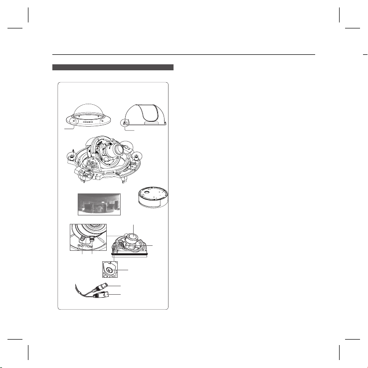
❖
Components of your camera
Your camera has the following components:
1
2
6
12
5
7
910
8 – DIGITAL COLOR DOME CAMERA
3
4
7
6
8
Lens
11
Video connector
Power connector
Dome cover: Covers the inner cover, lens, and
1.
main body to protect them.
Cover screw: Use it to assemble or
2.
disassemble both dome cover and case.
Inner cover: Covers the main body to protect it.
3.
.Wing locker: Push a long thin screwdriver into
4
its narrow spot and press it outward when you want
to remove the inner cover.
Main body: Includes a lens, a switch board, a
5.
PCB board, screws, and such.
Screws for assembly and disassembly: Using
6.
these 2 screws, the Main
body is closely connected to the Case.
Hooker: By pulling the left/right levers in the
7.
arrow direction, the Main body can be detached
from the Case.
Case: Used as a ceiling or wall fi xture. It is
8.
fi xed using four screws provided in the package.
Zoom lever: Using this lever, the lens zoom can
9.
be adjusted and fi xed.
Focus lever: Using this lever, the lens focus can
10.
be adjusted and fi xed.
Tilt fi xing screw: Using this screw, the slope of
11.
the lens can be adjusted and fi xed.
Cable: Connect the Video connector to BNC
12.
cable and Power connector to power adapter.
•
Introduction
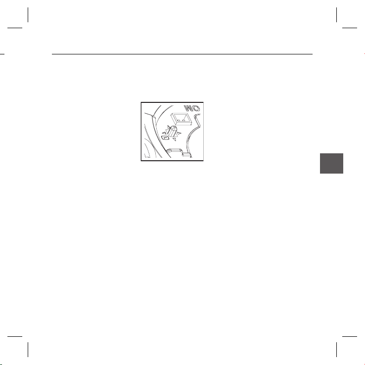
Setting switches❖
SETUP Switch
•
This switch is used to set the function or property. When this switch is pressed for at least 2 seconds, the
MAIN MENU appears.
ef
(Left/Right)
: By pressing this switch left or right, you can move left or right on the menu or change the
cd
(Up/Down) :
: When you press this switch in the menu, the selected function is confi rmed. To enter a submenu, press
this button.
displayed value.
By pressing this switch up or down, you can move up or down on the menu.
English – 9
ENG
Installation
I
e
e
o
Installing camera
Before installation
Before installing your camera, you have to read the following cautions:
You have to check whether the location (ceiling or wall) can bear fi ve times the weight of your camera.
Don’t let the cable to be caught in improper place or the electric line cover to be damaged. Otherwise it may
cause a breakdown or fi re. You can use wall mount adaptor (SADT-102WM), and pole mount adaptor (SADT-
100PM) for installing the camera on the wall or pipeline.
When installing your camera, don’t allow any person to approach the installation site. If you have any valuable
things under the place, move th
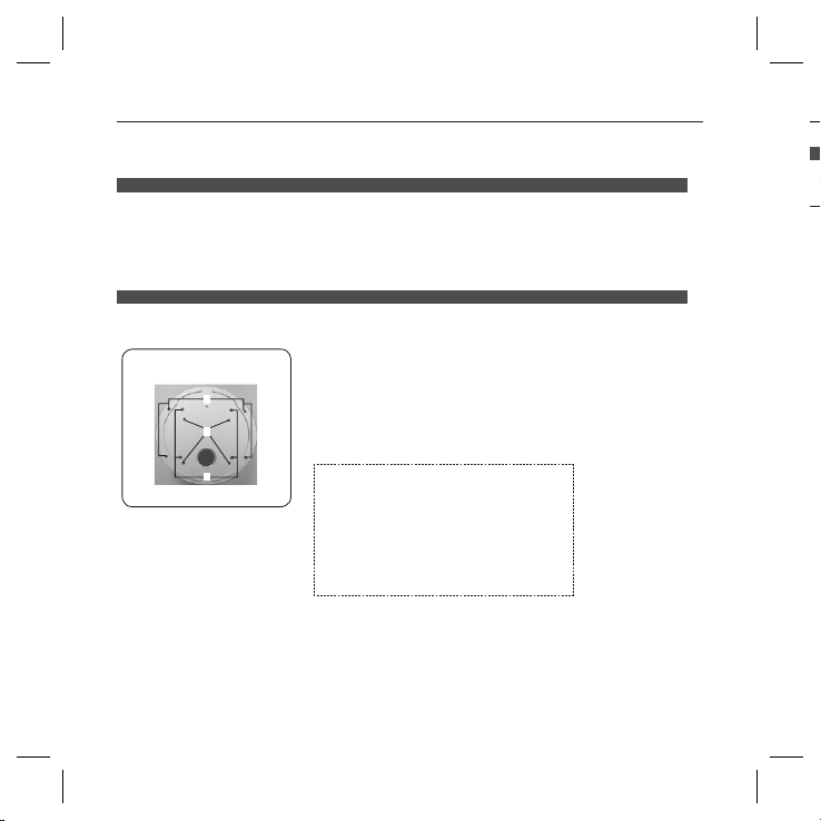
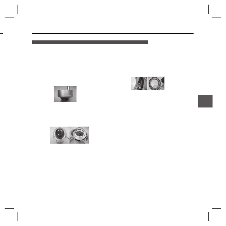
About the installation holes
Bottom of camera
A
B
C
em away.
A:Use these holes when directly installing your camera on the ceiling or
wall.
While those are not used, fi ll in the holes using the screw machine (M5
X L6.) for waterproofi ng.
B: Use four holes when directly installing your camera on the junction box
You can use the 4 1/8 diameter round type junction box for assembly.
(The junction box, gasket, and cover are separately purchased items.)
C: Use these holes when installing the wall mount adapter (SADT102WM)
While those are not used, fi ll in the holes using the screw machine (M5
for waterproofi ng.
X L6.)
The holes that are not used should be tightly
sealed up using the screws provided for
waterproofi ng. When the screws don’t have rubber
rings inside or are not closely attached, note that it
can cause waterproofi ng problem.
For attaching screws, see page 16
“Disassembling/assembling the Main body from
the Case.”
10 – DIGITAL COLOR DOME CAMERA
B
ar
T
1.
2.
Installing on a pipe
Before installation, you have to be familiar with the above cautions and fi ll in the holes that
are not used for installation.
To install your camera bottom on a pipe
1.
After connecting the power and video cables,
throw them inside the pipeline and screw the male
thread pipe into the female pipe thread in your
camera tightly to fix the
be sure to tape with Tefl on tape before assembly for
waterproofi ng. Be careful for the wiring cable not to
be stuck in the connection area.)
2.
Adjust the angle of the camera in search of a better
view.
1)
Separate the Dome cover using the L-Wrench
provided. (To make loose the screws, rotate
counterclockwise.)
2)
Adjust the lens direction. For more information,
see page 17 “Adjusting the camera direction.”
Main body
. (In this case,
3.
Attach the Dome cover. (Screw the connection bolts
tightly using the L-Wrench for waterproofi ng.)
To change the SAMSUNG logo position, move the
location of the connection rubber band as show
below and rotate for assembly. (The rotation limit
is 180 degree.)
Installation
ENG
English – 11
 Loading...