

Page 1

SCC-520(P)
ELECTRONICS
SCC-521(P)
SCC-523P
Printed In Korea
AB68-00390A
Digital Color Dome Camera
E
User Guide
Caméra de dôme colorée digitale
Manuel de l’utilisateur
Digitale Farb-Kuppelkamera
Benutzerhandbuch
Cámara Digital de la Bóveda del Color
Guía del usuario
Ditale Colore Dome Camera
Manuale d’uso
F
G
ES
I
Page 2

User Guide
User Guide
Contents
1. Overview
2. Component Name
3. Function of Each Component
4. Installation
Check what is inside the package
Notes on installation and usage
Cable connection
5. Specifications
.......................................................................
.....................................................................
...............................................................
3
........................................................
...................................
.....................
..........................
........................................................
4
5
6
6
6
7
9
1. Overview
CCTV COLOR DOME CAMERA SCC-520,521,520P,
521P,523P are the monitoring cameras incorporated
with the recent CCD that provides the best monitoring
function in connection with the CCTV system
equipment.
■ Number of CCD pixels
• SCC-520 : 270,000 pixels
• SCC-521 : 410,000 pixels
• SCC-520P : 320,000 pixels
• SCC-521P : 470,000 pixels
• SCC-523P : 470,000 pixels
■ Power supply
• DC 12V
■ Automatic function and special function
• ATW
• ELC(Electronic shutter iris)
E
2
3
Page 3

User Guide User Guide
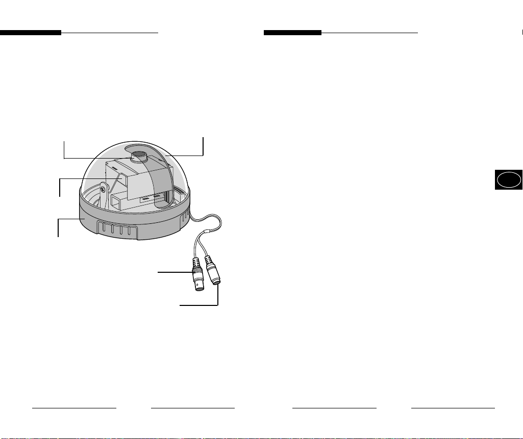
2. Component Name
Fixed focus lens
PCB board
Main body
Video cable
Power cable
Dome cover
3. Function of Each Component
■ Fixed focus lens
• Fixed focus lens installed on the camera.
Please take cautions that any dust or foreign
matter gathers on the front glass surface of
the lens.
■ Main body
• A body that supports the camera.
■ PCB board
• This part is quite important since it performs
the camera function. Please handle with care.
■ Power cable
• The terminal that is connected to the power
(adaptor) cable. Connect to DC 12V.
■ Video signal output cable
• The cable that sends the video signal.
■ Dome cover
• The transparent plastic cover that protects the
camera.
Be careful not to make a scratch on it.
E
4
5
Page 4

User Guide
User Guide
4. Installation
■ Check what is inside the package
• Check to see if the following parts are included in the
purchased package.
Camera
tab screw
■ Notes on installation and usage
1. Users should not disassemble the camera from the
front direction.
2. Always handle the camera with care. Please do not
apply a shock or vibration as much as possible and
take cautions not to cause damage or make a
scratch on the camera due to careless storage.
3. Please do not install the camera with the rainy place
or highly humid areas. And do not operate the
camera in the wet place.
4. Do not clean the camera body with the strong
abrasives or soaps. When the camera becomes
dirty, clean it with the dry rugs. Especially, make
sure to use the dedicated rugs for lens to clean the
dome cover.
5. Please keep the camera at the cool area that is not
exposed to the direct sunlight. If you do, it can
cause bad effects on the product.
User's guide
■ Cable connection
1. Hold the camera body with one hand and turn
the dome cover counterclockwise with other
hand in order to disassemble it.
E
2.Connect the BNC cable to the video cable
connector attached on the dome camera, and
connect the remained BNC cable to the video
input terminal of the monitor.
3.Connect the power adaptor at this time.
Connect the DC 12V power cable of the
connector to the power cable connection that is
attached on the dome camera.
Monitor
BNC Cable
Power Cable ( )
6
7
Page 5
User Guide
User Guide
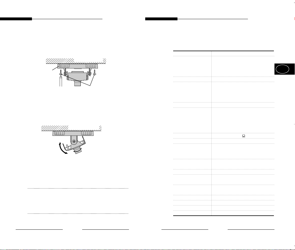
4. Attach the camera on the target location with
the screw driver using the provided tab screw.
Wall or ceiling
Main body
Screw Driver
Tab screw
5. Set the proper image by moving the camera
body (PCB board) inside the dome camera
upward or downward and set the focus by
turning the lens to the left or right direction.
Wall or ceiling
Adjust the
image upward
or downward
Adjust focus by
turning left or right
6. Assemble the dome cover by turning it
clockwise.
NOTE
Please make sure that any foreign matter gathers
on the lens cover when assembling or
disassembling the dome cover.
5. Specifications
Item Details
Broadcasting SCC-520/521 :NTSC
system STANDARD
Pick-up device 1/3" SUPER HAD IT CCD
Number of effective SCC-520 : 510(H) x 492(V)
pixel SCC-521 : 768(H) x 494(V)
Synchronization Internal
Resolution SCC-520/520P : 33 0 TV Lines (H)
Video output VBS 1.0Vp-p(75 , composite)
S/N ratio More than 50dB
Min. illumination SCC-520(P) : 1Lux(F2.0, 50 IRE)
Lens (focal length) SCC-520(P)/521(P) : f=3.8mm
Gamma correction 0.45
In/out connector Signal output: BNC, Power input :
Operating
temperature
Power source DC 12V
Power consumption 2 W
Size 100(ø) x 67(H)mm
Weight 150g
SCC-520P/521P/523P:PAL
STANDARD
SCC-520P: 500(H) x 582(V)
SCC-521P/523P : 752(H) x 582(V)
350 TV Lines (V)
SCC-521/521P/523P :
480 TV Lines (H)
350 TV Lines (V)
SCC-521(P)/523P :
2Lux(F2.0, 50 IRE)
SCC-523p : f=2.9mm
DC jack
-10~+50°C
E
8
9
Page 6

Inhalt
Benutzerhandbuch
1.
Überblick
Benutzerhandbuch
1.
Überblick
2.
Namen von Systemkomponenten
3.
Funktion jeder Systemkomponente
4. Installation
Kontrollieren, was in der Verpackung
enthalten ist
Anmerkungen über Installation und
Benutzung
Kabelanschluss
5.
Technische Daten
...............................................................
................................................................
..........................................................
..............................................................
.....................................................
.............................................
..................
.....................
3
CCTV Farb-Kuppelkamera SCC-520N/520P ist
eine Überwachungskamera, die über die neueste
CCD Bildwandler verfügt, der für die beste
4
Überwachungsfunktion in Verbindung
mit der CCTV Systemanlage sorgt.
5
6
6
6
7
9
■ CCD Bildelemente
• SCC-520 : 270,000 pixels
• SCC-521 : 410,000 pixels
• SCC-520P : 320,000 pixels
• SCC-521P : 470,000 pixels
• SCC-523P : 470,000 pixels
■ Stromversorgung
• 12V Gleichstrom
■ Automatische Funktion und spezielle
Funktion
• ATW Funktion (Automatische
Weißabgleichsfunktion)
• ELC(Elektronische IRIS Blende)
G
2
3
Page 7

Inhalt
Benutzerhandbuch
1.
Überblick
Benutzerhandbuch
1.
Überblick
2.
Namen von Systemkomponenten
3.
Funktion jeder Systemkomponente
4. Installation
Kontrollieren, was in der Verpackung
enthalten ist
Anmerkungen über Installation und
Benutzung
Kabelanschluss
5.
Technische Daten
...............................................................
................................................................
..........................................................
..............................................................
.....................................................
.............................................
..................
.....................
3
CCTV Farb-Kuppelkamera SCC-520N/520P ist
eine Überwachungskamera, die über die neueste
CCD Bildwandler verfügt, der für die beste
4
Überwachungsfunktion in Verbindung
mit der CCTV Systemanlage sorgt.
5
6
6
6
7
9
■ CCD Bildelemente
• SCC-520 : 270,000 pixels
• SCC-521 : 410,000 pixels
• SCC-520P : 320,000 pixels
• SCC-521P : 470,000 pixels
• SCC-523P : 470,000 pixels
■ Stromversorgung
• 12V Gleichstrom
■ Automatische Funktion und spezielle
Funktion
• ATW Funktion (Automatische
Weißabgleichsfunktion)
• ELC(Elektronische IRIS Blende)
G
2
3
Page 8

Inhalt
Benutzerhandbuch
1.
Überblick
Benutzerhandbuch
1.
Überblick
2.
Namen von Systemkomponenten
3.
Funktion jeder Systemkomponente
4. Installation
Kontrollieren, was in der Verpackung
enthalten ist
Anmerkungen über Installation und
Benutzung
Kabelanschluss
5.
Technische Daten
...............................................................
................................................................
..........................................................
..............................................................
.....................................................
.............................................
..................
.....................
3
CCTV Farb-Kuppelkamera SCC-520N/520P ist
eine Überwachungskamera, die über die neueste
CCD Bildwandler verfügt, der für die beste
4
Überwachungsfunktion in Verbindung
mit der CCTV Systemanlage sorgt.
5
6
6
6
7
9
■ CCD Bildelemente
• SCC-520 : 270,000 pixels
• SCC-521 : 410,000 pixels
• SCC-520P : 320,000 pixels
• SCC-521P : 470,000 pixels
• SCC-523P : 470,000 pixels
■ Stromversorgung
• 12V Gleichstrom
■ Automatische Funktion und spezielle
Funktion
• ATW Funktion (Automatische
Weißabgleichsfunktion)
• ELC(Elektronische IRIS Blende)
G
2
3
Page 9

Inhalt
Benutzerhandbuch
1.
Überblick
Benutzerhandbuch
1.
Überblick
2.
Namen von Systemkomponenten
3.
Funktion jeder Systemkomponente
4. Installation
Kontrollieren, was in der Verpackung
enthalten ist
Anmerkungen über Installation und
Benutzung
Kabelanschluss
5.
Technische Daten
...............................................................
................................................................
..........................................................
..............................................................
.....................................................
.............................................
..................
.....................
3
CCTV Farb-Kuppelkamera SCC-520N/520P ist
eine Überwachungskamera, die über die neueste
CCD Bildwandler verfügt, der für die beste
4
Überwachungsfunktion in Verbindung
mit der CCTV Systemanlage sorgt.
5
6
6
6
7
9
■ CCD Bildelemente
• SCC-520 : 270,000 pixels
• SCC-521 : 410,000 pixels
• SCC-520P : 320,000 pixels
• SCC-521P : 470,000 pixels
• SCC-523P : 470,000 pixels
■ Stromversorgung
• 12V Gleichstrom
■ Automatische Funktion und spezielle
Funktion
• ATW Funktion (Automatische
Weißabgleichsfunktion)
• ELC(Elektronische IRIS Blende)
G
2
3
Page 10

Inhalt
Benutzerhandbuch
1.
Überblick
Benutzerhandbuch
1.
Überblick
2.
Namen von Systemkomponenten
3.
Funktion jeder Systemkomponente
4. Installation
Kontrollieren, was in der Verpackung
enthalten ist
Anmerkungen über Installation und
Benutzung
Kabelanschluss
5.
Technische Daten
...............................................................
................................................................
..........................................................
..............................................................
.....................................................
.............................................
..................
.....................
3
CCTV Farb-Kuppelkamera SCC-520N/520P ist
eine Überwachungskamera, die über die neueste
CCD Bildwandler verfügt, der für die beste
4
Überwachungsfunktion in Verbindung
mit der CCTV Systemanlage sorgt.
5
6
6
6
7
9
■ CCD Bildelemente
• SCC-520 : 270,000 pixels
• SCC-521 : 410,000 pixels
• SCC-520P : 320,000 pixels
• SCC-521P : 470,000 pixels
• SCC-523P : 470,000 pixels
■ Stromversorgung
• 12V Gleichstrom
■ Automatische Funktion und spezielle
Funktion
• ATW Funktion (Automatische
Weißabgleichsfunktion)
• ELC(Elektronische IRIS Blende)
G
2
3
Page 11

Inhalt
Benutzerhandbuch
1.
Überblick
Benutzerhandbuch
1.
Überblick
2.
Namen von Systemkomponenten
3.
Funktion jeder Systemkomponente
4. Installation
Kontrollieren, was in der Verpackung
enthalten ist
Anmerkungen über Installation und
Benutzung
Kabelanschluss
5.
Technische Daten
...............................................................
................................................................
..........................................................
..............................................................
.....................................................
.............................................
..................
.....................
3
CCTV Farb-Kuppelkamera SCC-520N/520P ist
eine Überwachungskamera, die über die neueste
CCD Bildwandler verfügt, der für die beste
4
Überwachungsfunktion in Verbindung
mit der CCTV Systemanlage sorgt.
5
6
6
6
7
9
■ CCD Bildelemente
• SCC-520 : 270,000 pixels
• SCC-521 : 410,000 pixels
• SCC-520P : 320,000 pixels
• SCC-521P : 470,000 pixels
• SCC-523P : 470,000 pixels
■ Stromversorgung
• 12V Gleichstrom
■ Automatische Funktion und spezielle
Funktion
• ATW Funktion (Automatische
Weißabgleichsfunktion)
• ELC(Elektronische IRIS Blende)
G
2
3
Page 12

Inhalt
Benutzerhandbuch
1.
Überblick
Benutzerhandbuch
1.
Überblick
2.
Namen von Systemkomponenten
3.
Funktion jeder Systemkomponente
4. Installation
Kontrollieren, was in der Verpackung
enthalten ist
Anmerkungen über Installation und
Benutzung
Kabelanschluss
5.
Technische Daten
...............................................................
................................................................
..........................................................
..............................................................
.....................................................
.............................................
..................
.....................
3
CCTV Farb-Kuppelkamera SCC-520N/520P ist
eine Überwachungskamera, die über die neueste
CCD Bildwandler verfügt, der für die beste
4
Überwachungsfunktion in Verbindung
mit der CCTV Systemanlage sorgt.
5
6
6
6
7
9
■ CCD Bildelemente
• SCC-520 : 270,000 pixels
• SCC-521 : 410,000 pixels
• SCC-520P : 320,000 pixels
• SCC-521P : 470,000 pixels
• SCC-523P : 470,000 pixels
■ Stromversorgung
• 12V Gleichstrom
■ Automatische Funktion und spezielle
Funktion
• ATW Funktion (Automatische
Weißabgleichsfunktion)
• ELC(Elektronische IRIS Blende)
G
2
3
Page 13

Inhalt
Benutzerhandbuch
1.
Überblick
Benutzerhandbuch
1.
Überblick
2.
Namen von Systemkomponenten
3.
Funktion jeder Systemkomponente
4. Installation
Kontrollieren, was in der Verpackung
enthalten ist
Anmerkungen über Installation und
Benutzung
Kabelanschluss
5.
Technische Daten
...............................................................
................................................................
..........................................................
..............................................................
.....................................................
.............................................
..................
.....................
3
CCTV Farb-Kuppelkamera SCC-520N/520P ist
eine Überwachungskamera, die über die neueste
CCD Bildwandler verfügt, der für die beste
4
Überwachungsfunktion in Verbindung
mit der CCTV Systemanlage sorgt.
5
6
6
6
7
9
■ CCD Bildelemente
• SCC-520 : 270,000 pixels
• SCC-521 : 410,000 pixels
• SCC-520P : 320,000 pixels
• SCC-521P : 470,000 pixels
• SCC-523P : 470,000 pixels
■ Stromversorgung
• 12V Gleichstrom
■ Automatische Funktion und spezielle
Funktion
• ATW Funktion (Automatische
Weißabgleichsfunktion)
• ELC(Elektronische IRIS Blende)
G
2
3
Page 14

Inhalt
Benutzerhandbuch
1.
Überblick
Benutzerhandbuch
1.
Überblick
2.
Namen von Systemkomponenten
3.
Funktion jeder Systemkomponente
4. Installation
Kontrollieren, was in der Verpackung
enthalten ist
Anmerkungen über Installation und
Benutzung
Kabelanschluss
5.
Technische Daten
...............................................................
................................................................
..........................................................
..............................................................
.....................................................
.............................................
..................
.....................
3
CCTV Farb-Kuppelkamera SCC-520N/520P ist
eine Überwachungskamera, die über die neueste
CCD Bildwandler verfügt, der für die beste
4
Überwachungsfunktion in Verbindung
mit der CCTV Systemanlage sorgt.
5
6
6
6
7
9
■ CCD Bildelemente
• SCC-520 : 270,000 pixels
• SCC-521 : 410,000 pixels
• SCC-520P : 320,000 pixels
• SCC-521P : 470,000 pixels
• SCC-523P : 470,000 pixels
■ Stromversorgung
• 12V Gleichstrom
■ Automatische Funktion und spezielle
Funktion
• ATW Funktion (Automatische
Weißabgleichsfunktion)
• ELC(Elektronische IRIS Blende)
G
2
3
Page 15

Inhalt
Benutzerhandbuch
1.
Überblick
Benutzerhandbuch
1.
Überblick
2.
Namen von Systemkomponenten
3.
Funktion jeder Systemkomponente
4. Installation
Kontrollieren, was in der Verpackung
enthalten ist
Anmerkungen über Installation und
Benutzung
Kabelanschluss
5.
Technische Daten
...............................................................
................................................................
..........................................................
..............................................................
.....................................................
.............................................
..................
.....................
3
CCTV Farb-Kuppelkamera SCC-520N/520P ist
eine Überwachungskamera, die über die neueste
CCD Bildwandler verfügt, der für die beste
4
Überwachungsfunktion in Verbindung
mit der CCTV Systemanlage sorgt.
5
6
6
6
7
9
■ CCD Bildelemente
• SCC-520 : 270,000 pixels
• SCC-521 : 410,000 pixels
• SCC-520P : 320,000 pixels
• SCC-521P : 470,000 pixels
• SCC-523P : 470,000 pixels
■ Stromversorgung
• 12V Gleichstrom
■ Automatische Funktion und spezielle
Funktion
• ATW Funktion (Automatische
Weißabgleichsfunktion)
• ELC(Elektronische IRIS Blende)
G
2
3
Page 16
2. Namen von
Systemkomponenten
Fixiertes
Fokusobjektiv
PCB Brett
Halterung
Videokabel
Netzkabel
Benutzerhandbuch Benutzerhandbuch
3.
Funktion jeder
Systemkomponente
■ Fixiertes Objektiv
Kuppelabd
eckung
• Fixiertes Objektiv in der Kameraeinheit
integriert. Bitte achten Sie darauf, dass kein
Staub oder kein fremder Gegenstand auf die
frontale Glasoberfläche des Objektivs
gelangt.
■ Haterung
• Halterungsvorrichtung, die die Kameraeinheit
stützt.
■ PCB Brett
• Dieses Teil ist sehr wichtig, weil es die
Kamerafunktion durchführt.
Bitte vorsichtig anfassen.
■ Netzkabel
• Kabelstecker, der am Adapterkabel
angeschlossen wird. An DC 12V anschließen.
■ Kabel für Videosignalausgang
• Kabel, das den Videosignal sendet.
■ Kuppelabdeckung
• Durchsichtige PVC Kuppelhülle, die die
Kameraeinheit schützt.
Achten Sie darauf, dass kein Kratz darauf
entsteht.
G
4
5
Page 17

Benutzerhandbuch
Benutzerhandbuch
4.
Installation
■
Kontrollieren, was in der Verpackung enthalten ist
• Überprüfen Sie, ob die folgenden Teile in der
erworbenen Packung enthalten sind.
Kameraeinheit
■
Anmerkungen über Installation und Benutzung
1. Benutzer dürfen die Kameraeinheit nicht von der Frontseite
her zerlegen.
2. Fassen Sie die Kamera immer vorsichtig an. Bitte beugen
Sie jeden Anschlag oder jede Vibration möglichst vor und
achten Sie darauf, dass bei Lagerung die Kameraeinheit
nicht beschädigt oder gekratzt wird.
3. Bitte installieren Sie die Kamera bitte nicht in Regen
ausgesetzten Plätzen oder im hohen Grad feuchten
Bereichen. Nehmen Sie die Kameraeinheit nicht im nassen
Platz in Betrieb.
4. Reinigen Sie die Kameraeinheit nicht mit starken
Putzmitteln oder Seifen. Wenn die Kamera verschmutzt ist,
reinigen Sie sie mit einem trockenen Tuch. Besonders zum
Reinigen der Kuppelabdeckung verwenden Sie ein zum
Reinigen eines Objektivs geeignetes Putztuch.
5. Platzieren Sie die Kameraeinheit an einem kühlen Bereich,
wo kein direktes Sonnenlicht fällt. Andernfalls kann es zum
Schaden des Produkts führen.
Befestigung
s-schrauben
Betriebsanleitung
6
■ Kabelanschluss
1. Halten Sie die Kamerahalterung mit einer Hand
fest und drehen Sie die Kuppelhülle nach links mit
anderer Hand, um sie abzubauen.
2. Schließen Sie das BNC-Kabel an den in der
Kuppelkamera integrierten Videokabelstecker an
und schließen Sie das restliche BNC-Kabel an den
Videeingangspol des Monitors an.
3. Schließen Sie jetzt den Netzadapter an. Schließen
Sie das DC 12V Netzkabel des Netzteils an den in
der Kameraeinheit angefügten Netzkabelstecker an.
Beim Anschließen des AC Eingangs des Adapters
stellen Sie vorher den Spannungauswahlschalter auf
110V oder 220V ein.
Monitor
BNC Kabel
Netzkabel ( )
7
G
Page 18

Benutzerhandbuch
Benutzerhandbuch
4. Bringen Sie die Kameraeinheit an Zielort mit dem
Schraubenzieher mit den mitgelieferten
Befestigungsschrauben an.
Wand oder Decke
Halterung
Befestigungs
Schraubenzieher
schrauben
5. Stellen Sie korrektes Kamerabild ein, indem Sie das
Kameragehäuse (PCB-Brett) innerhalb der
Kuppelkamera aufwärts oder abwärts verschieben,
und justieren Sie ein, indem Sie das Objektiv nach
links oder nach rechts drehen.
Wand oder Decke
Das Bild durch
Verschieben
aufwärts oder
abwärts justieren
Den Fokus durch
Drehen nach links
oder nach rechts
justieren
6. Bauen Sie die Kuppelabdeckung ein, indem Sie sie
nach rechts drehen.
Anmerkung
Achten Sie bitte beim Zusammenbauen oder
Zerlegen besonders darauf, dass keine
Fremdkörper in die Objektivkappe gelangen.
5.
Technische Daten
Artikel Spezifikation
Fernsehnorm SCC-520/521 :NTSC
(Signalsystem) STANDARD
CCD-Sender 1/3" SUPER HAD CCD-Sender
Effektive SCC-520 : 510(H) x 492(V)
Bildelmente SCC-521 : 768(H) x 494(V)
Synchronisation Intern
Auflösung SCC-520/520P : 330 TV Zeilen (H)
Videoausgangssignal VBS 1.0Vp-p bei 75 , gemischt
Signal/Rausch
abstand
Min. Belleuchtung SCC-520(P) : 1Lux(F2.0, 50 IRE)
eines abgebildeten SCC-521(P)/523P :
Objekts 2Lux(F2.0, 50 IRE)
Objektiv SCC-520(P)/521(P) : f=3.8mm
( Brennpunkt) SCC-523p : f=2.9mm
Gamma-Korrektur 0.45
Anschlüsse für Signalausgang: BNC Buchse
Ein/Ausgang Netzeingang : DC Buchse
Betriebs
temperatur
Betribsspannung 12V Gleichstrom
Leistungsaufnahme 2 W
Abmessungen 100(ø) x 67(H)mm
Gewicht 150g
SCC-520P/521P/523P:PAL
STANDARD
SCC-520P: 500(H) x 582(V)
SCC-521P/523P : 752(H) x 582(V)
350 TV Zeilen (V)
SCC-521/521P/523P :
480 TV Zeilen (H)
350 TV Zeilen (V)
Mehr als 50dB
-10~+50°C
G
8
9
 Loading...