

Page 1

512X POWER ZOOM CAMERA
SCC-С4233(P)/С4333(P)/
С4235(P)/С4335(P)
User Manual
ENG RUS POL
Page 2

SafetyPrecautions
CAUTION
RISK OF ELECTRIC SHOCK.
DO NOT OPEN.
CAUTION: TO REDUCE THE RISK OF ELECTRIC SHOCK,
DO NOT REMOVE COVER (OR BACK)
NO USER-SERVICEABLE PARTS INSIDE
REFER SERVICING TO QUALIFIED SERVICE PERSONNEL
This symbol indicates that
dangerous voltage consisting
a risk of electric shock is
present within this unit.
This symbol indicates
that there are important
operating and maintenance
instructions in the literature
accompanying this unit.
WARNING
• To reduce the risk of re or electric
shock, do not expose this appliance
to rain or moisture.
WARNING
1. Be sure to use only the standard
adapter that is specied in the
specication sheet. Using any
other adapter could cause re,
electrical shock, or damage to
the product.
2. Incorrectly connecting the power
supply or replacing battery may
cause explosion, re, electric
22
shock, or damage to the product.
3. Do not connect multiple cameras
to a single adapter. Exceeding
the capacity may cause
abnormal heat generation or re.
4.
Securely plug the power cord into
the power receptacle. Insecure
connection may cause re.
5. When installing the camera,
fasten it securely and rmly.
A falling camera may cause
personal injury.
6. Do not place conductive objects
(e.g. screwdrivers, coins, metal
things, etc.) or containers lled
with water on top of the camera.
Doing so may cause personal
injury due to re, electric shock,
or falling objects.
7.
Do not install the unit in humid,
dusty, or sooty locations. Doing so
may cause re or electric shock.
8. If any unusual smells or smoke
come from the unit, stop using
the product. In such case,
immediately disconnect the
power source and contact the
service centre. Continued use in
such a condition may cause re
or electric shock.
Page 3

3
ENG
9. If this product fails to operate
normally, contact the nearest
service centre. Never
disassemble or modify this
product in any way. (SAMSUNG
is not liable for problems caused
by unauthorized modications or
attempted repair.)
10. When cleaning, do not spray
water directly onto parts of the
product. Doing so may cause re
or electric shock.
as sun, as this may damage the
CCD image sensor.
8. Apparatus shall not be exposed
to dripping or splashing and no
objects lled with liquids, such
as vases, shall be placed on the
apparatus.
9. The Mains plug is used as a
disconnect device and shall stay
readily operable at any time.
CAUTION
1. Do not drop objects on the
product or apply strong shock
to it. Keep away from a location
subject to excessive vibration or
magnetic interference.
2. Do not install in a location
subject to high temperature (over
122°F), low temperature (below
14°F), or high humidity. Doing so
may cause re or electric shock.
3. If you want to relocate the
already installed product, be
sure to turn off
the power and then move or
reinstall it.
4.
Remove the power plug from the
outlet when then there is a lightning.
Neglecting to do so may cause re
or damage to the product.
5. Keep out of direct sunlight and
heat radiation sources. It may
cause re.
6. Install it in a place with good
ventilation.
7. Avoid aiming the camera directly
towards extremely bright objects
such
Page 4

ImportantSafetyInstructions
1. Read these instructions.
2. Keep these instructions.
3. Heed all warnings.
4.
Follow all instructions.
5.
Do not use this apparatus near water.
6. Clean only with dry cloth.
7. Do not block any ventilation openings.
Install in accordance with the manufacturer’s instructions.
8. Do not install near any heat sources such as radiators, heat registers, or
other apparatus (including ampliers) that produce heat.
9. Do not defeat the safety purpose of the polarized or grounding-type
plug. A polarized plug has two blades with one wider than the other. A
grounding type plug has two blades and a third grounding prong. The
wide blade or the third prong is provided for your safety. If the provided
plug does not t into your outlet, consult an electrician for replacement of
the obsolete outlet.
10. Protect the power cord from being walked on or pinched particularly at
plugs, convenience receptacles, and the point where they exit from the
apparatus.
11. Only use attachments/accessories specied by the manufacturer.
12. Use only with cart, stand, tripod, bracket, or table specied by the
manufacturer, or sold with the apparatus.
13. Unplug this apparatus. When a cart is used, use caution when moving
the cart/apparatus combination to avoid injury from tip-over.
14. Refer all servicing to qualied service personnel. Servicing is required
when the apparatus has been damaged in any way, such as powersupply cord or plug is damaged, liquid has been spilled or objects have
fallen into the apparatus, the apparatus has been exposed to rain or
moisture, does not operate normally, or been dropped.24. Wall or Ceiling
Mounting – The product should be mounted to a wall or ceiling only as
recommended by the manufacturer.
4
Page 5

5
ENG
Contents
Safety Precautions ...... 2
Important Safety
Instructions ..................... 4
Overview ........................... 6
Special Features ........... 7
Part Names and
Functions ......................... 8
Installation ....................... 11
Before Installation ......... 11
Checking the contents
of the package .................. 11
Things to keep in mind during
installation and use .............11
Installing the Camera ... 12
Power Adapter Cable........ 12
Video Cable ...................... 12
Connecting the Cables
.. 13
Camera Setup ................ 16
CAMERA ID ........................ 17
IRIS ...................................... 17
WDR... ............................. 18
ALC... ............................... 18
MANU... ........................... 19
SHUTTER ......................... 19
AGC ................................... 20
MOTION ............................ 21
WHITE BAL ...................... 21
FOCUS MODE ................. 23
MOTION DET ................... 24
DAY/NIGHT ...................... 26
DAY... ............................... 27
NIGHT... ........................... 27
AUTO... ............................ 28
EXT .................................. 29
PRIVACY ........................... 29
SPECIAL ........................... 30
LANGUAGE ..................... 31
VIDEO SET ...................... 31
RS-485 ............................. 32
ZOOM SPEED ................. 33
DIGITAL ZOOM ............... 33
DISPLAY ZOOM .............. 34
SYSTEM INFO ................ 34
CTRL TYPE ..................... 35
V-SYNC ............................ 35
PRESET ............................ 36
Product
Specifications ................ 37
Page 6

Overview
This enriched WDR (Wide Dynamic Range) Day/Night camera can
clearly implement both dark and bright parts on the screen with the
dual shutter.
When a bright object such as window occupies a part of the
screen, it appears white in conventional cameras. But using the
state-of-the-art WDR function that this camera provides, you can
see the clear image. This Day/Night camera activates the colour
mode when in the illumination over the normal value. Otherwise it
activates B/W (Black/White) mode by removing the IR cut function,
which can improve the sensitivity for identifying objects even in a
dark area. It also incorporated the low speed shutter and Sens-Up
(Uses the field accumulation method) functions to enhance the low
illumination feature.
This camera can be mainly used in the dark places such as
basement parking lots under comparatively low illumination. In
daytime, it displays the colour screen with a horizontal resolution of
540 lines but at night, it uses the Day/Night feature along with the
Sens-Up function to identify objects in a dark area. You can also
connect the infrared ray emission equipment to this camera.
Moreover, this camera has more various functions for surveillance.
White Balance function that provides accurate colour rendition under
any light conditions. Auto Focus function that automatically tracks
and focuses on the moving subject. Privacy Zone function to hide
a special area for privacy protection. RS485/ Wired remote control
function.
Note
SCC-C4233(P)/C4333(P) does not support for WDR function.
SCC-C4233(P)/C4235(P) does not support for V-SYNC function.
6
Page 7

7
ENG
Special Features
High Sensitivity
It implements images of high sensitivity using the up-to-date
Super-HAD IT CCD(SCC-C4233(P)/C4333(P))/ExView-HAD PS
CCD(SCC-C4235(P)/C4335(P)).
WDR
The WDR function of this camera is the state-of-the-art technology
that can effectively enlarge the range for screen gain. It is mainly
used for taking photos for window scenes inside a building. Using
this technology, you can clearly see both indoor and outdoor
images, and can enjoy the excellent picture quality, which is
enabled by automatically adjusting the WDR level.
Note
SCC-C4233(P)/C4333(P) does not support for WDR function.
Low Illumination
It uses the digital signal technologies such as low illumination and
Day/Night functions that make your camera identify objects even in
the worst environment.
Superior Backlight Adjustment
When an object has a bright illumination or sunlight behind it, this
camera automatically improves the shaded object picture quality.
Digital Power Synchronization
The full digital Line Lock function directly adjusts the vertical
camera synchronization to enhance the operation ability and
reliability of this camera.
Note
SCC-C4233(P)/C4235(P) dose not support for Line Lock function.
High Resolution
This camera has realized high resolution of 540 lines using the
top-notch full digital image processing and special algorithm technologies.
Output Signal Setting
You can set the following Video output signals: Image reversion
(Horizontal, Vertical, or both), Privacy, Horizontal/Vertical profiling,
POSI/NEGA function, and digital zooming.
White Balance
It uses to automatically adjust light levels to improve colour balance
depending on the illumination.
Auto Focus
It enables to capture clear images by adjusting the automatic focus
on the subject movement.
Page 8
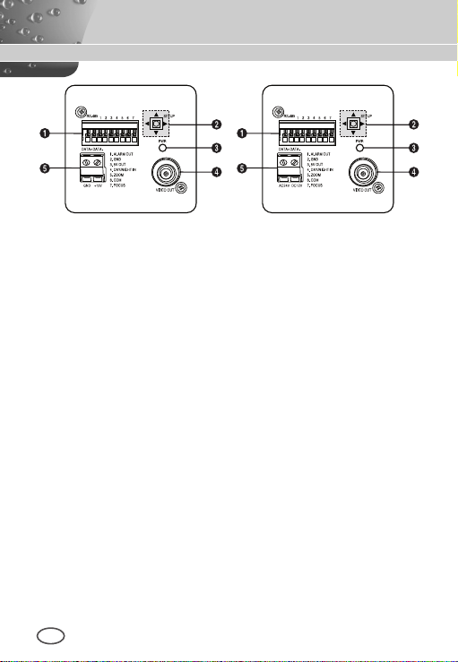
PartNamesandFunctions
SCC-C4233(P)/C4235(P) SCC-C4333(P)/C4335(P)
1 Input/Output Connector
This connector has input and output jacks for RS-485 control
signals.
RS-485 DATA+
Jack for connection to RS-485 DATA+ signal line.
RS-485 DATA-
Jack for connection to RS-485 DATA- signal line.
1. ALARM OUT
Alarm out jack for motion detection. (Open Collector, On Gnd)
2. GND
Grounding jack.
3. 5V OUT
Power supply jack for RS-485 JIG. Use within typical DC +5V
100mA.
4. DAY/NIGHT IN
This is a function to receive the external DAY/NIGHT signal from
the sensor(option) and convert the signal into BW.
8
Page 9

9
ENG
5-7. ZOOM/ FOCUS REMOTE terminals
This port is used for ZOOM/FOCUS, MENU CONTROL, HOME
RETURN, and ONEAF by using an external controller.
Depending on the input condition, 4 modes, A, B, C, and D are
available. (SPECIAL - CTRL TYPE)
(Operation Voltage Range : +3V~+13V, -3V~-13V)
1) When the voltage is supplied to either ZOOM or FOCUS port
Function
*1
Code
Tele(Up)
A -6V +6V -6V +6V
B -6V +6V +6V -6V
C +6V -6V -6V +6V
D
+6V -6V +6V -6V
Wide(Down)
ZOOM Port FOCUS Port
Near(Left) Far(Right)
*1: During MENU OFF, controls ZOOM/FOCUS and during
MENU ON, changes the direction, Up/Down/Left/Right
SETUP switch.
Page 10

2) When the voltage is supplied to both ports
Function
Code
ENTER/AF *2 HOME RETURN *3
ZOOM Port
FOCUS Port
ZOOM Port
FOCUS Port
A -6V -6V +6V +6V
B -6V +6V +6V -6V
C +6V -6V -6V +6V
D
+6V +6V -6V -6V
* 2 : For short voltage supply during MENU OFF, executes
ONEAF and for more than 2 second
* 3 : For more than 2 second long voltage supply, moves to the
PRESET 0(HOME) position.
2 SETUP Switch
This switch is used to set the function or property. When this switch
is pressed for at least 2 seconds, the Setup menu appears.
n
[Left/Right] movement or changing the displayed value: By
pressing this switch left or right, you can move left or right on
the menu or change the displayed value.
n
[Up/Down] movement: By pressing this switch up or down, you
can move up or down on the menu.
n
Setting: When you press this switch in the menu, the selected
value or function is confirmed. To enter a submenu, press this
button.
3 Power Display LED
When the power is normally connected, the red LED lights.
4 Video OUT Jack
This is connected to the Video Input jack of the monitor and it
outputs the Video signals.
5 Power Connection Jack
This is connected to the Power cable.
10
Page 11

11
ENG
Installation
Before Installation
❚
Checking the contents of the package
Make sure that the following items are included in the package.
Camera Camera Holder
(Power Adapter)
2 Screws
Things to keep in mind during installation and use
n
Do not disassemble the camera on your own.
n
Always be careful when handling the camera. Do not strike the
camera by your fists or shake it. Please be careful not to be
careless when storing and operating it.
n
Do not place or operate the camera in any wet environment
such as rain or wet surfaces.
n
Do not clean the camera with rough sandpaper. Please always
use a dry cloth when cleaning it.
n
Put the camera in a cool area free from direct sunlight.
Otherwise, the camera may be damaged.
User's Manual
Page 12
Installing the Camera
❚
To install and use the camera, rst prepare the following cables.
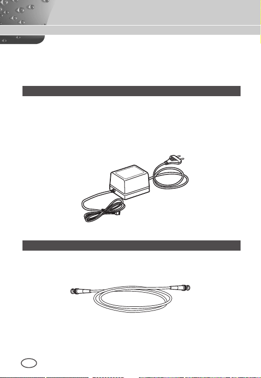
Power Adapter Cable (sold separately)
The requirements for the power adapter, which connects to the
camera’s POWER IN terminal, are as follows:
- SCC-C4233(P)/C4235(P) : DC 12V 600mA
- SCC-C4333(P)/C4335(P) : AC 24V 300mA
DC 12V 600mA
Video Cable
Use a BNC cable, such as the one shown below, to connect the
camera’s VIDEO OUT to the monitor.
12
Page 13

13
ENG
Connecting the Cables
❚
1. Connect one end of the BNC cable to the VIDEO OUT.
2. Connect the other end of the BNC cable to the VIDEO IN of the
monitor.
Video In Terminal of
Monitor Rear Surface
BNC cable
Video Out Terminal
Page 14

3. Plug in the power adapter. Use a “minus” screwdriver to connect one
part of the power adapter, which consists of two lines, to the POWER
terminal of the camera as follows :
SCC-C4333(P)/C4335(P) SCC-C4233(P)/C4235(P)
4. Determine the type of power supply and set the POWER
SELECTION switch accordingly. Next, plug the power adapter into a
wall outlet.
14
Page 15

15
ENG
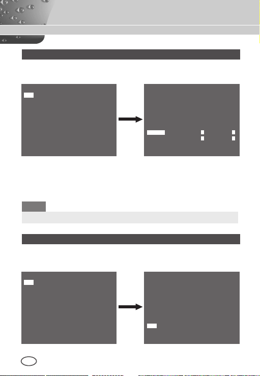
5. If the camera operates normally, the following screen will be
displayed for 5 seconds and then disappears.
SAMSUNG PROTOCOL
ADDRESS 0
TYPE RS-485, HALF
BAUD RATE 9600
ROM VER 1.000
EEP VER 1.000
LENS OK.
* ROM VER and EEP VER may change without notice.
6. The requirements for RS485 control is as follows :
- Signaling Speed: 9600 bps
- Data Bit : 8 bits
- Stop Bit : 1 bit
- Parity Bit : none
Page 16

CameraSetup
This chapter describes how to congure the camera-related settings. If you
press the SETUP switch for at least 2 seconds, the Setup menu appears.
The Setup OSD (On-screen Display) map brief is like the following:
CAMERA ID OFF/ON...
IRIS WDR...*1/ALC.../MANU...
SHUTTER
AGC/MOTION OFF/LOW/HIGH
WHITE BAL ATW1/ATW2/AWC/MANU...
FOCUS MODE AF/MF/ONEAF
MOTION DET OFF/ON...
DAY/NIGHT DAY.../NIGHT.../AUTO.../EXT
PRIVACY OFF/ON...
SPECIAL ... LANGUAGE *
PRESET ...
Note
*1 SCC-C4233(P)/C4333(P) does not support for WDR function.
*2 The language may vary depending on sales region.
*3 SCC-C4233(P)/C4235(P) does not support for V-SYNC function.
OFF/AUTO X2 ~ AUTO X256
/1/100(1/120) ~ 1/10K
S.SLOW/SLOW/NORM/
FAST/F.FAST
2
VIDEO SET ...
RS-485 ...
ZOOM SPEED 1~4
DIGITAL ZOOM OFF/X2~X16
DISPLAY ZOOM OFF/ON
SYSTEM INFO ...
CTRL TYPE A/B/C/D
3
V-SYNC *
RET
INT/LINE...
16
Page 17

17
ENG
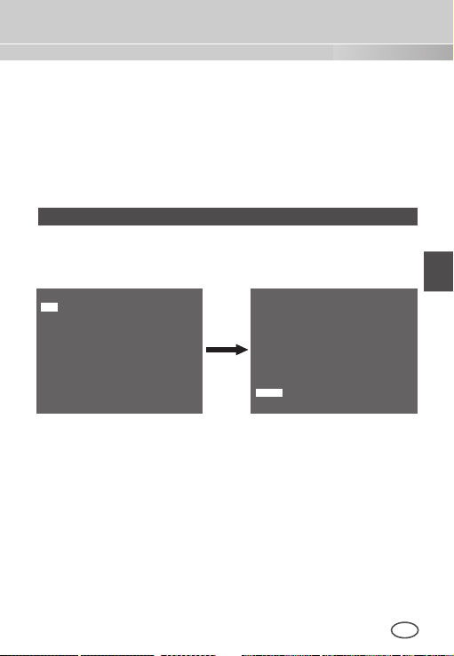
❚
CAMERA ID
The [CAMERA ID] menu is used to assign a camera ID to this
camera. If you press the SETUP switch when the [CAMERA ID]
menu is selected, the corresponding setup screen appears.
CAMERA ID ON...
IRIS ALC...
SHUTTER OFF
AGC HIGH
WHITE BAL ATW2
FOCUS MODE AF
MOTION DET OFF
DAY/NIGHT DAY...
PRIVACY OFF
SPECIAL ...
PRESET ...
EXIT QUIT
(CAMERA ID)
ABCDEFGHIJKLMNOPQRSTUVWXYZ
0123456789 : ! - + * ()
RET
SP▶▶ ◀◀SP LOCATION...
CAMERA-1...........
/
You can input a camera ID composed of alphabets, numbers, and
special characters up to 20 characters long. The input camera
ID can be displayed at the desired location when using the
[LOCATION…] submenu. When you press the SETUP switch in
[RET], the screen returns to the upper menu.
❚
IRIS
The [IRIS] menu is used to set the automatic light control method
for this camera.
Page 18
WDR...
If you press the SETUP switch when the [WDR…] submenu is
selected, the corresponding screen appears.
CAMERA ID OFF
IRIS WDR...
SHUTTER OFF
AGC HIGH
WHITE BAL ATW2
FOCUS MODE AF
MOTION DET OFF
DAY/NIGHT DAY...
PRIVACY OFF
SPECIAL ...
PRESET ...
EXIT QUIT
(WDR)
LEVEL1 L – – – I – – – H
LEVEL2 L – – – I – – – H
WHITE BAL INDOOR
RET
You can adjust the shutter speed in [LEVEL1] and the brightness in
[LEVEL2]. You can also select any of [ALL], [OUTDOOR], and [INDOOR] in [WHITE BAL]. In case of [ALL], this camera controls both
indoor and outdoor images.
Note
SCC-C4233(P)/C4333(P) does not support for WDR function.
ALC...
If you press the SETUP switch when the [ALC…] submenu is se-
lected, the corresponding screen appears.
CAMERA ID OFF
IRIS ALC...
SHUTTER OFF
AGC HIGH
WHITE BAL ATW2
FOCUS MODE AF
MOTION DET OFF
DAY/NIGHT DAY...
PRIVACY OFF
SPECIAL ...
PRESET ...
EXIT QUIT
(ALC)
BLC OFF
LEVEL ( 0) – – – – I – – – –
RET
18
Page 19
19
ENG
You can make the BLC (Back Light Compensation) function active or
not. For setting the BLC zone, you can select any of [BOTTOM…],
[TOP…], [LEFT…], [RIGHT…], and [CENTER…]. The actual location
is displayed when you enter each item.
In case of [USER…], you can set the desired BLC zone by defining
the size and location. You can set the Video output level in [LEVEL].
Its selectable range is from -9 to +9.
MANU…
If you press the SETUP switch after selecting MANU in the IRIS
item, an additional screen appears in which you can set manually
opening or closing the IRIS.
CAMERA ID OFF
IRIS MANU...
SHUTTER OFF
AGC HIGH
WHITE BAL ATW2
FOCUS MODE AF
MOTION DET OFF
DAY/NIGHT DAY...
PRIVACY OFF
SPECIAL ...
PRESET ...
EXIT QUIT
SHUTTER
❚
(MANUAL)
LEVEL ( 00) – – – – I – – – –
RET
The [SHUTTER] menu is used to set the high speed electronic
shutter and AUTO low speed shutter. The high speed electronic
shutter can be used 7 different speeds and is commonly used for
imaging fast moving objects. (NTSC: from 1/100 to 1/10K, PAL:
from 1/120 to 1/10K ). The AUTO low speed electronic shutter can
be any of 13 speeds from X2 to X256 and it slows the shutter speed
to make images clearer in dark illumination. If you select an AUTO
low speed, the shutter speed is automatically lowered depending on
the darkness level.
Page 20

CAMERA ID OFF
IRIS ALC...
SHUTTER AUTO X2
MOTION F.FAST
WHITE BAL ATW2
FOCUS MODE AF
MOTION DET OFF
DAY/NIGHT DAY...
PRIVACY OFF
SPECIAL ...
PRESET ...
EXIT QUIT
If you keep pressing the Left/Right SETUP switch, shutter speeds
toggles in the following order:
OFF à AUTO X2 à AUTO X4 à AUTO X6 à AUTO X8 à AUTO X12
à AUTOX16 à AUTO X24 à AUTO X32 à AUTO X48
AUTO X64
à
1/100(1/120)
à
AGC
❚
The AGC (Auto Gain Control) menu is used to set the AGC level
of the camera. When the AGC is active, the camera automatically
increases the sensitivity by amplifying the Video signal when the
strength of the signal falls below the normal value.
Only when [OFF] or a high speed shutter is selected in the
[SHUTTER] menu, you can set the AGC level.
You can select any of [OFF], [LOW], and [HIGH].
AUTO X96
à
1/250
à
CAMERA ID OFF
IRIS ALC...
SHUTTER OFF
AGC HIGH
WHITE BAL ATW2
FOCUS MODE AF
MOTION DET OFF
DAY/NIGHT DAY...
PRIVACY OFF
SPECIAL ...
PRESET ...
EXIT QUIT
à
à
1/500
AUTO X128
à
1/1000
à
à
1/2000
AUTO X256
1/4000
à
à
à
OFF
1/10K
Note
When the DAY/NIGHT is set to AUTO, the AGC is displayed with
[---] so you cannot change its setting.
20
Page 21

21
ENG
MOTION
❚
The [MOTION] menu is used to set the intensity of the camera
AGC level for monitoring motions. This function is available only in
AUTO low speed mode. You can select any of [S.SLOW], [SLOW],
[NORM], [FAST], and [F.FAST] according to the AGC intensity level.
CAMERA ID OFF
IRIS ALC...
SHUTTER AUTO X2
MOTION F.FAST
WHITE BAL ATW2
FOCUS MODE AF
MOTION DET OFF
DAY/NIGHT DAY...
PRIVACY OFF
SPECIAL ...
PRESET ...
EXIT QUIT
To monitor very fast moving objects in dark illumination, select
[F.FAST]. To monitor non-moving objects in dark illumination, select
[S.SLOW].
WHITE BAL
❚
The [WHITE BAL] menu is used to configure the white balance related
settings for this camera.
CAMERA ID OFF
IRIS ALC...
SHUTTER OFF
AGC HIGH
WHITE BAL ATW2
FOCUS MODE AF
MOTION DET OFF
DAY/NIGHT DAY...
PRIVACY OFF
SPECIAL ...
PRESET ...
EXIT QUIT
Page 22
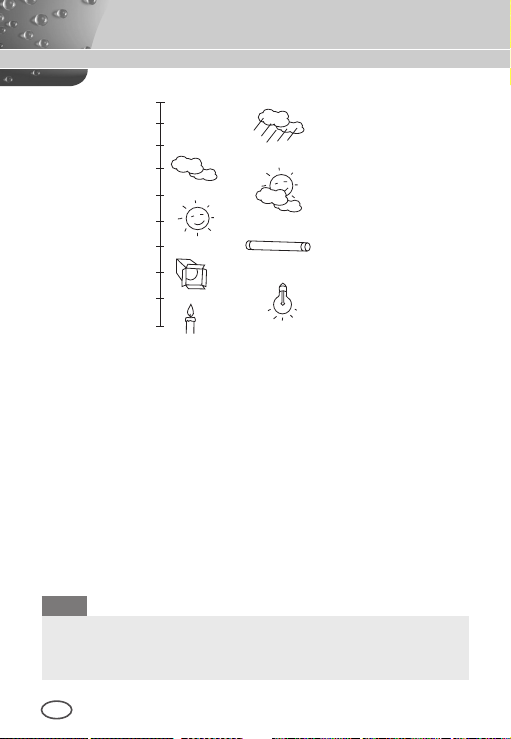
10000K
9000K
8000K
7000K
6000K
5000K
4000K
3000K
2000K
1000K
Blue sky
Rainy
Cloudy
Partly Cloudy
Sunny
Fluorescent lamp
Halogen lamp
Tungsten lamp
Candlelight
To adjust the white balance, 4 different modes are provided as follows:
●
[ATW1] (Auto Tracing White Balance mode 1): The camera can
automatically adjust the colour temperature in real time according
to the ambient temperature change. The colour temperature
variation range is approximately from 2500°K to 9300°K.
●
[ATW2]: Its colour temperature variation range is approximately
from 2000°K to 10000°K.
●
[AWC ] (Auto White Balance Control): The colour temperature
setting is made once. After selecting this, expose to an object to
memorize the colour temperature of it and press the SETUP switch.
The fixed colour temperature is applied.
●
[MANU…]: You can manually set the current colour temperature.
You can also specify the settings for red and blue colours on your
own.
Note
When the [DAY/NIGHT] is set to [NIGHT], [WHITE BAL] is
displayed with “---“. You cannot adjust the settings manually.
When it is set to [COLOR] in the [NIGHT] mode, the white balance
will be setting as the same value in [COLOR] mode.
22
Page 23

23
ENG
FOCUS MODE
❚
In the [FOCUS MODE] menu, the focus method can be set to
AF(Auto Focus), MF(Manual Focus), or ONEAF(One Auto Focus).
CAMERA ID OFF
IRIS ALC...
SHUTTER OFF
AGC HIGH
WHITE BAL ATW2
FOCUS MODE AF
MOTION DET OFF
DAY/NIGHT DAY...
PRIVACY OFF
SPECIAL ...
PRESET ...
EXIT QUIT
●
[AF]: In the Auto Focus mode, you can monitor the screen continuously
and it will focus automatically. If you manually adjust the focus,
it operates as the same in Manual Focus mode. It automatically sets
the focus after the zoom moves.
●
[MF]: In the Manual Focus mode, you can adjust the focus manually.
●
[ONEAF]: In the ONEAF mode, it automatically sets the focus after the
zoom moves, and operates as the same in the Manual Focus mode if
the zoom does not move.
Note
※ AF function may not be possible with types of objects listed
below. For such objects, focus manually.
- High intensity objects or objects illuminated with low lighting
- Objects shot through wet or dirty glass
- Pictures that are a mixture of distant and nearby objects
- White walls and other single-colour objects
- Venetian blinds and other horizontally striped objects
Page 24

MOTION DET
❚
[MOTION DET] menu is used to configure the motion detection related
settings. If you press the SETUP switch when [ON…] is selected in the
[MOTION DET] menu, the corresponding screen appears.
CAMERA ID OFF
IRIS ALC...
SHUTTER OFF
AGC HIGH
WHITE BAL ATW2
FOCUS MODE AF
MOTION DET ON...
DAY/NIGHT DAY...
PRIVACY OFF
SPECIAL ...
PRESET ...
EXIT QUIT
(MOTION DET)
TYPE 1
AREA 0* 1* 2* 3*
DISPLAY ON
SENSITIVITY L – – – I – – – H
RET
You cannot change the setting for type 2 because it is prefixed with the
full screen. In case of 1 and 3, you can set the motion detection area
on your own.
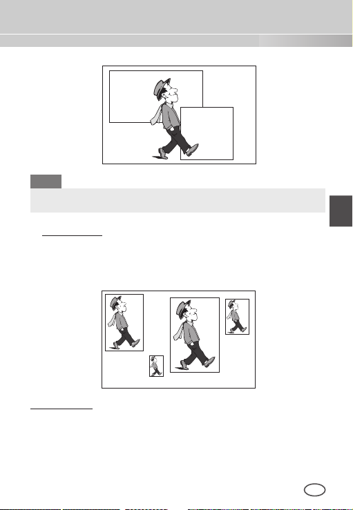
Those 3 types are like the following:
1. Window Type
The selected area is displayed with a box. The motion can be
detected for the area only. You can manually set the motion
detection area. You can use the Up/Down/Left/Right SETUP
switch to set the size. To move to [POSITION], press the SETUP
switch. After setting the position using the Up/Down/Left/Right
SETUP switch, press the SETUP switch to move to the upper
menu. To set the size and position for [AREA], select any of 0, 1,
2, and 3.
24
Page 25
25
ENG
Window0
Window1
Note
The selected window for AREA is displayed in white and the
unselected one is displayed in black.
2. Label Type
The box-typed motion detection area is prefixed. The detected
area is displayed with size and position changing. You cannot
change [AREA] because it is displayed with [---].
Label2
Label1
Label3
3. Block Type
The screen displays with small blocks. When a motion is detected in
the selected blocks, the small blocks are displayed on the screen.
n
[PRESET]: The whole screen becomes the motion detection area.
n
[USER...]: You can manually set the motion detection area. Use the
Up/Down/Left/Right SETUP switch to set the area. To erase the
selected block, press the SETUP switch.
Label0
Page 26

To select [RET], press UP key on the top block or press DOWN
key on the bottom block and then press ENTER key to return a
upper menu.
In order to set the motion detection area on your own, you have
to specify the size and location for the area setting. When [ON]
is selected in [DISPLAY], the detected motion is displayed on the
screen and the camera sends the Alarm Out signal. You can also
assign the sensitivity for motion detection.
Note
※ MOTION DET menu is not available for the first 5 seconds after
operating the PAN/TILT/ZOOM/FOCUS/IRIS functions.
※ Since the motion detecting function depends on the brightness
of selected area, it may dysfunction due to the different
brightness between the background and object.
DAY/NIGHT
❚
The [DAY/NIGHT] menu is used to configure the day and night
related settings for this camera. This camera can turn the IR
(Infrared) filter on or off.
CAMERA ID OFF
IRIS ALC...
SHUTTER OFF
AGC HIGH
WHITE BAL ATW2
FOCUS MODE AF
MOTION DET OFF
DAY/NIGHT DAY...
PRIVACY OFF
SPECIAL ...
PRESET ...
26
EXIT QUIT
Page 27

27
ENG
DAY...
If you press the SETUP switch when the [DAY…] submenu is
selected, the corresponding screen appears. You can set the values
for [C-GAIN] when the DAY… submenu is selected. You can set the
values for [AGC COLOR] and [AGC DETAIL] while the AGC menu is
selected.
(DAY)
C-GAIN (7) – – – – – – – I
AGC COLOR ( 0) – – – – I – – – –
AGC DETAIL (0) I – – – – – – –
RET
Note
When the value of [AGC DETAIL] becomes large, it also makes
the noise stand out.
NIGHT...
If you press the SETUP switch when the [NIGHT…] submenu is
selected, the corresponding screen appears.
(NIGHT)
COLOR/BW BW...
RET
Page 28

(BW)
(COLOR)
BURST OFF
RET
Even in the Night mode, you can see colour images in bright
illumination. Therefore, you can select any of [COLOR…] and [BW…].
In case of [COLOR…], you have to set the colour temperature for white
balance. You can also specify the settings for red and blue colours on
your own. In case of [BW...], the burst signals are output with the BW
Composite Video signals, when the BURST is set to [ON]. And no burst
WHITE BAL ATW2
RET
signals are output when the BURST is set to [OFF].
Note
When it is set to [NIGHT], [WHITE BAL] of the video set will be
displayed as “---“. You cannot adjust the settings manually.
When it is set to [COLOR] in the NIGHT mode, the white balance
will be setting as the same value in [COLOR] mode.
AUTO…
This automatically converts the Day mode to the Night mode and
vice versa depending on illumination. In low illumination, it removes
the IR ltering function to raise the sensitivity. Otherwise, it activates
the IR ltering function to lower the sensitivity.
If you press the SETUP switch when the [AUTO…] submenu is
selected, the corresponding screen appears.
(AUTO)
LEVEL ( 0) I – – – – – –
DAY NIGHT 2 S
NIGHT DAY 5 S
28
RET
Page 29

29
ENG
For this function, you can specify the level for each conversion
between [DAY] and [NIGHT].
Note
When the [DAY/NIGHT] is set to [AUTO], the AGC is displayed
with [---] so you cannot change its setting.
EXT
This automatically converts the colour mode to the BW mode and
vice versa by interfacing with an external sensor.
CAMERA ID OFF
IRIS ALC...
SHUTTER OFF
AGC HIGH
WHITE BAL ATW2
FOCUS MODE AF
MOTION DET OFF
DAY/NIGHT EXT
PRIVACY OFF
SPECIAL ...
PRESET ...
EXIT QUIT
PRIVACY
❚
The [PRIVACY] menu is used to configure the privacy related settings
for this camera. If you press the SETUP switch when [ON…] is selected
in the [PRIVACY] menu, the corresponding screen appears.
CAMERA ID OFF
IRIS ALC...
SHUTTER OFF
AGC HIGH
WHITE BAL ATW2
FOCUS MODE AF
MOTION DET OFF
DAY/NIGHT DAY...
PRIVACY ON...
SPECIAL ...
PRESET ...
EXIT QUIT
(PRIVACY ZONE MAP)
0
1
2
6
7
8
12
13
14
15
STYLE 4
RET
3
4105
9
11
Page 30

PRIVACY ZONE SET 0
<ZOOM/FOCUS>...
<SIZE>...
<LOCATION>...
COLOR ...
EXIT QUIT
You can set 16 privacy zones in total. For configuration for 0 to 15
zones, you have to set the size, location, and colour.
Note
※ For the safer privacy protection, select about 10 % more than the
actual area to hide when you set up the PRIVACY ZONE area.
※ The mosaic of the recorded images is set to be the PRIVACY
ZONE. The mosaic of the recorded images can not be recovered
after recording.
SPECIAL
❚
The [SPECIAL] menu is used to configure the special settings for this
camera. If you press the SETUP switch when […] is selected in the
[SPECIAL] menu, the corresponding screen appears.
CAMERA ID OFF
IRIS ALC...
SHUTTER OFF
AGC HIGH
WHITE BAL ATW2
FOCUS MODE AF
MOTION DET OFF
DAY/NIGHT DAY...
PRIVACY ON...
SPECIAL ...
PRESET ...
EXIT QUIT
30
(SPECIAL)
LANGUAGE ENGLISH
VIDEO SET ...
RS-485 ...
ZOOM SPEED 4
DIGITAL ZOOM OFF
DISPLAY ZOOM OFF
SYSTEM INFO ...
CTRL TYPE A
V-SYNC INT
RET
Page 31

31
ENG
LANGUAGE
You can change the OSD language using the Left/Right SETUP switch.
Note
Selectable languages may vary depending on sales region.
VIDEO SET
The [VIDEO SET] menu is used to congure the privacy related settings for this camera. If you press the SETUP switch when [ON…] is
selected in the [PRIVACY] menu, the corresponding screen appears.
(SPECIAL)
LANGUAGE ENGLISH
VIDEO SET ...
RS-485 ...
ZOOM SPEED 4
DIGITAL ZOOM OFF
DISPLAY ZOOM OFF
SYSTEM INFO ...
CTRL TYPE A
V-SYNC INT
RET
(VIDEO SET)
DNR OFF
FLICKERLESS OFF
REVERSE OFF
DETAIL (2) – – I –
Y-LEVEL (0) I – – –
C-LEVEL (0) I – – –
POSI/NEGA +
RET
DNR
DNR(Digital Noise Reduction) function enables the picture to be
reduced noise.
(VIDEO SET)
DNR ON
FLICKERLESS OFF
REVERSE OFF
DETAIL (2) – – I –
Y-LEVEL (0) I – – – – – – – –
C-LEVEL (0) I – – – – – – – –
POSI/NEGA +
RET
Page 32

FLICKERLESS
When this is set to [ON], the shutter speed is set to 1/100 sec (for
NTSC) or 1/120 sec (for PAL) to prevent from flickering by the
discordance between vertical synchronization frequency and
on-and-off frequency of the light.
REVERSE
It is used to mirror video signals horizontally, vertically, or both.
DETAIL
It is used to control the horizontal or vertical distinction.
Y-LEVEL
It is used to set the levels for the Sync signal and the entire brightness
signal of the video signal.
C-LEVEL
It is used to set the levels for the Burst signal and the entire colour
signal of the video signal.
POSI/NEGA
It is used to output as it is, or mirror the video brightness signal.
RS-485
If you press the SETUP switch when [...] is selected in the [RS-485]
menu, the corresponding screen appears.
(SPECIAL)
LANGUAGE ENGLISH
VIDEO SET ...
RS-485 ...
ZOOM SPEED 4
DIGITAL ZOOM OFF
DISPLAY ZOOM OFF
SYSTEM INFO ...
CTRL TYPE A
V-SYNC INT
RET
(RS-485)
PROTOCOL SAMSUNG
BAUD RATE 9600
ADDRESS 0
RET
You can set the PROTOCOL, BAUD RATE, and ADDRESS (range: 0
to 255) for this communication.
32
Page 33

33
ENG
ZOOM SPEED
(SPECIAL)
LANGUAGE ENGLISH
VIDEO SET ...
RS-485 ...
ZOOM SPEED 4
DIGITAL ZOOM OFF
DISPLAY ZOOM OFF
SYSTEM INFO ...
CTRL TYPE A
V-SYNC INT
RET
Use the Left/Right SETUP switch in the [ZOOM SPEED] menu to
select the speed.
1 : Slowest speed
2 : Low speed
3 : High speed
4 : Fastest speed
DIGITAL ZOOM
You may set up the digital zoom magnication ratio in the [DIGITAL
ZOOM] menu. The magnication ratio ranges from [OFF] to 16 times.
If you set Digital Zoom of the camera to maximum 16 times, the
mode will become the 32 time optical zoom and you will be able to
enlarge a subject by maximum 512 times. Use the Left/Right SETUP
switch to select a magnication ratio in the [DIGITAL ZOOM] menu.
(SPECIAL)
LANGUAGE ENGLISH
VIDEO SET ...
RS-485 ...
ZOOM SPEED 4
DIGITAL ZOOM X16
DISPLAY ZOOM OFF
SYSTEM INFO ...
CTRL TYPE A
V-SYNC INT
RET
Page 34

DISPLAY ZOOM
In the [DISPLAY ZOOM] menu, you can display the ZOOM scale on
the screen.
(SPECIAL)
LANGUAGE ENGLISH
VIDEO SET ...
RS-485 ...
ZOOM SPEED 4
DIGITAL ZOOM OFF
DISPLAY ZOOM ON
SYSTEM INFO ...
CTRL TYPE A
V-SYNC INT
RET
X32
Note
When the [DAY/NIGHT] is set to [AUTO], the AGC is displayed
with [---] so you cannot change its setting.
SYSTEM INFO
This [SYSTEM INFO] menu is used to check the system-related in-
formation. If you press the SETUP switch when the [SYSTEM INFO]
menu is selected, the corresponding setup screen appears.
(SPECIAL)
LANGUAGE ENGLISH
VIDEO SET ...
RS-485 ...
ZOOM SPEED 4
DIGITAL ZOOM OFF
DISPLAY ZOOM OFF
SYSTEM INFO ...
CTRL TYPE A
V-SYNC INT
RET
(SYSTEM INFO)
ROM VER 1.000
EEP VER 1.000
PROTOCOL SAMSUNG
ADDRESS 0
COMM. TYPE RS-485, HALF
BAUD RATE 9600
SERIAL NO. 000000000000000
RET
You can nd the system information about ROM version, EEP version,
protocol, address, type, baudrate, and serial number.
34
Page 35

35
ENG
CTRL TYPE
By inputting the wire remote port, you may set up the A, B, C or D mode.
Code
A -6V +6V +6V -6V
B -6V +6V -6V +6V
C +6V -6V +6V -6V
D +6V -6V -6V +6V
Tele
Wide
Far
Near
V-SYNC
You can select a vertical synchronization mode between [INT] and
[LINE]. In case of [INT], the camera uses the inside crystal oscillator
for synchronization. In case of [LINE], the camera uses the frequency
of the external power for synchronization.
Note
- In case of [LINE], SCC-C4333(P)/SCC-C4335(P) doesn’t support
for DC 12V, which [- - -] is displayed.
- SCC-C4233(P)/C4235(P) does not support for V-SYNC function.
Page 36

PRESET
❚
Select the [PRESET] menu and press the SETUP switch and the
[PRESET MAP] submenu screen will appear.
(PRESET MAP)
1
2
H0
6
5
11
10
16
15
21
20
26
25
31
30
HOME RETURN OFF
EXIT QUIT
3
7
8
12
13
17
18
22
23
27
28
RET
4
9
14
19
24
29
PRESET NO. 0
POSITION SET ...
PRESET ID ON...
EXIT QUIT
Select the PRESET number and press the SETUP switch and the
above screen will appear.
POSITION SET
It is used to memorize the position of ZOOM or FOCUS.
PRESET ID
It is used to designate the ID on the basis of the PRESET position as
the [CAMERA ID].
Note
[HOME RETURN] automatically returns to the HOME position if
there is no key input for a certain time. The HOME position is set
to PRESET 0 if it is saved, or [Off] if not.
HOME RETURN Time Setup
OFF à 1MIN à 2MIN à 3~60MIN à 2 HOUR à 3~12 HOUR
36
Page 37

37
ENG
Product Specications
Item Details
Product type CCTV Camera
Power source
Broadcast type
Power
consumption
Image device
Effective pixels SCC-C4233(5)/C4333(5) : 768(H) x 494(V)
Scanning line
frequency
Synchronization
mode
Resolution 540(COLOR)/570(BW) TV Lines
S/N Ratio Approx. 50dB
SCC-C4233(P)/SCC-C4235(P) : DC 12V±10%
SCC-C4333/C4335 : AC 24V ± 10% (60Hz ± 0.3Hz)
SCC-C4333P/C4335P : AC 24V ± 10% (50Hz ± 0.3Hz)
SCC-C4233(5)/C4333(5) : NTSC Standard Colour System
SCC-C4233(5)P/C4333(5)P : PAL Standard Colour System
SCC-C4233(P) : 4W
SCC-C4235(P) : 5W
SCC-C4333(P) : 5W
SCC-C4335(P) : 5.5W
SCC-C4233(P)/C4333(P) : 1/4” Super-HAD IT CCD
SCC-C4235(P)/C4335(P) : 1/4” ExView-HAD PS CCD
SCC-C4233(5)P/C4333(5)P : 752(H) x 582(V)
Horizontal: NTSC 15,734Hz(INT)/15,750Hz(LL)
PAL 15,625Hz(INT)/15,625Hz(LL)
Vertical: NTSC 59.94Hz(INT)/60Hz(LL)
PAL 50Hz(INT)/50Hz(LL)
INT/Line Lock
(SCC-C4233(P)/C4235(P) does not support for Line
Lock function.)
Page 38

Item Details
Min. Scene
Illumination
Wide Dynamic
Range
Electronic
shutter speed
Condition
Illumination
50IRE Off 2.0 0.20 1.2 0.12
30IRE Off 1.2 0.12 0.7 0.07
15IRE Off 0.6 0.06 0.3 0.03
50IRE x256 0.008 0.0008 0.005 0.0005
30IRE x256 0.005 0.0005 0.003 0.0003
15IRE x256 0.002 0.0002 0.001 0.0001
SCC-C4233(P)/C4333(P) : N/A
SCC-C4235/C4335 : x128
SCC-C4235P/C4335P : x160
High Speed: OFF~1/10K sec
Low Speed: OFF~X256
SCC-C4233(P)/C4333(P) SCC-C4235(P)/C4335(P)
Sens-up Colour B/W Colour B/W
DIGITAL ZOOM 2x ~ 16x
White Balance ATW1/ATW2/AWC/MANUAL Mode
(3200°K, 5600°K, R/B Gain adjustment)
Signal output COMPOSITE VIDEO OUT : 1.0 Vp-p 75 ohms/BNC
Operation
-10°C~+50°C
temperature
Operation
~90%
humidity
Size NET(WxHxD) : SCC-C4233(5)(P) : 60.5x59.5x125.2
SCC-C4333(5)(P) : 60.5x59.5x159.2
Weight NET : SCC-C4233(5)(P) : 444g
SCC-C4333(5)(P) : 595g
GROSS : SCC-C4233(5)(P) : 552g
SCC-C4333(5)(P) : 717g
38
Page 39

Memo
Correct Disposal of This Product
(Waste Electrical & Electronic Equipment)
(Applicable in the European Union and other European countries with
separate collection systems)
This marking shown on the product or its literature, indicates that it
should not be disposed with other household wastes at the end of its
working life. To prevent possible harm to the environment or human
health from uncontrolled waste disposal, please separate this from other
types of wastes and recycle it responsibly to promote the sustainable
reuse of material resources.
Household users should contact either the retailer where they purchased
this product, or their local government office, for details of where and how
they can take this item for environmentally safe recycling.
Business users should contact their supplier and check the terms and
conditions of the purchase contract. This product should not be mixed
with other commercial wastes for disposal.
Page 40

Page 41

ВИДЕОКАМЕРА С 512Х УВЕЛИЧЕНИЕМ И
ВАРИОФОКАЛЬНЫМ ОБЪЕКТИВОМ
SCC-С4233(P)/С4333(P)/
С4235(P)/С4335(P)
Руководство пользователя
RUS
Page 42

Мерыпредосторожности
ВНИМАНИЕ
ОПАСНОСТЬ ПОРАЖЕНИЯ ЭЛЕКТРИЧЕСКИМ
ТОКОМ. НЕ ОТКРЫВАТЬ
ВНИМАНИЕ: ВО ИЗБЕЖАНИЕ ПОРАЖЕНИЯ ЭЛЕКТРИЧЕСКИМ ТОКОМ, НЕ
СНИМАЙТЕ ЗАДНЮЮ КРЫШКУ. ВНУТРИ НЕТ ДЕТАЛЕЙ, ОБСЛУЖИВАЕМЫХ
ПОЛЬЗОВАТЕЛЕМ. ДЛЯ ТЕХНИЧЕСКОГО ОБСЛУЖИВАНИЯ ОБРАЩАЙТЕСЬ К
КВАЛИФИЦИРОВАННОМУ СПЕЦИАЛИСТУ.
Этот символ обозначает, что
внутри устройства имеется
опасное напряжение, которое
может привести к поражению
электрическим током.
Этот символ указывает, что
в документации на изделие
имеется важная инструкция
по его использованию или
обслуживанию.
ПРЕДУПРЕЖДЕНИЕ
Во избежание повреждений, следствием
которых может быть пожар или
поражение электрическим током, не
допускайте попадания данного изделия
под дождь или в условия высокой
влажности.
ПРЕДУПРЕЖДЕНИЕ
1. Пользуйтесь только стандартным
блоком питания, который указан в листе
спецификаций. Использование любого
другого блока питания может привести к
пожару, поражению электрическим током
или к повреждению изделия.
2. Неправильное подключение блока
питания или замена батареи может
привести к взрыву, пожару, поражению
электрическим током или к повреждению
изделия.
3. Не подключайте несколько видеокамер
к одному блоку питания. Превышение
нагрузочной способности блока питания
может привести к его перегреву или к
пожару.
4. Надежно вставьте вилку сетевого
шнура в розетку сети переменного
тока. Ненадежное подключение может
привести к пожару.
5. При установке видеокамеры закрепите
ее прочно и надежно. Падение
видеокамеры может привести к травме.
6. Не кладите сверху на видеокамеру
токопроводящие предметы
(например, отвертки, монеты и другие
металлические предметы) и не ставьте
на нее наполненные водой сосуды.
Невыполнение этих требований
может привести к пожару, поражению
электрическим током или к травмам в
результате падения этих предметов.
7. Не устанавливайте изделие во влажных,
запыленных или покрытых копотью
помещениях. Невыполнение этого
требования может привести к пожару
или к поражению электрическим током.
8. Если вы почувствуете странный запах
или обнаружите дым, выходящий из
изделия, прекратите эксплуатацию.
В этом случае следует немедленно
отсоединить изделие от источника
питания и связаться с сервисным
центром. Продолжение эксплуатации
изделия в таком состоянии может
привести к пожару или к поражению
электрическим током.
Page 43

9. При обнаружении неисправности
в изделии свяжитесь с ближайшим
сервисным центром. Никогда не
разбирайте данное изделие и не вносите
изменений в его конструкцию. (Компания
Samsung не несет ответственности
за проблемы, возникшие в результате
внесения изменений в конструкцию
изделия или в результате попыток
самостоятельно выполнить ремонт
изделия).
10. При чистке изделия не разбрызгивайте
на него воду. Это может привести к
пожару или к поражению электрическим
током.
ВНИМАНИЕ
1. Не роняйте на изделие никакие
предметы и не ударяйте по нему. Не
устанавливайте изделие в местах
с сильной вибрацией или вблизи
источников магнитного поля.
2. Не устанавливайте изделие в местах с
высокой (выше 50°С) или низкой (ниже
-10°С) температурой или с высокой
влажностью. Это может привести к
пожару или к поражению электрическим
током.
3. Если вы хотите переместить ранее
установленное изделие на новое место,
отключите перед этим питание изделия.
4. Во время грозы отсоедините шнур
питания видеокамеры от розетки сети
переменного тока. Невыполнение этого
требования может привести к пожару
или к повреждению изделия.
5. Устанавливайте изделие так, чтобы на
него не падал прямой солнечный свет
и чтобы рядом не было источников,
излучающих тепло. Это может привести
к пожару.
6. Изделие должно устанавливаться в
помещении с хорошей вентиляцией.
7. Избегайте направлять видеокамеру
прямо на очень яркие объекты,
например, на солнце, так как это может
привести к повреждению матрицы ПЗС,
формирующей изображение.
8. Изделие должно быть защищено от
воздействия капель или брызг воды и
на него нельзя помещать наполненные
водой сосуды, например, вазы с цветами.
9. Вилка сетевого шнура используется в
качестве отсоединяющего от питания
устройства и к ней всегда должен быть
обеспечен легкий доступ.
RUS
Page 44

Важныеправилатехникибезопасности
1. Прочтите эти правила.
2. Сохраните эти правила.
3. Принимайте во внимание все предупреждения.
4. Следуйте всем правилам.
5. Не используйте изделие вблизи воды.
6. Чистите изделие только сухой салфеткой.
7. Не загораживайте никакие вентиляционные отверстия. Выполните установку
изделия в соответствии с инструкциями изготовителя.
8. Не устанавливайте изделие рядом с источниками тепла, такими, как радиаторы,
решетки системы отопления, или другими устройствами, которые генерируют тепло
(включая усилители).
9. В целях безопасности не отказывайтесь от использования вилок поляризованного
или заземляющего типа. Вилка поляризованного типа имеет два ножевых контакта,
один из которых шире другого. Вилка заземляющего типа имеет два контакта
и третий заземляющий штырь. Широкое лезвие третьего заземляющего штыря
предусмотрено для вашей безопасности. Если вилка поставляемого вместе с
аппаратом шнура питания не подходит для вашей розетки, попросите опытного
электрика заменить старую розетку.
10. Не наступайте на шнур питания и не допускайте его защемления, особенно вблизи
от штепсельной вилки, в месте подключения к розетке и там, где шнур выходит из
изделия.
11. Пользуйтесь только теми приспособлениями/ принадлежностями, которые
рекомендованы изготовителем.
12. Используйте изделие только с тележкой, кронштейном, штативом, держателем или
подставкой, предусмотренными изготовителем или поставляемыми в комплекте с
изделием.
13. Перед перемещением изделия отсоедините его от электросети. Если используется
тележка, соблюдайте осторожность при перемещении тележки с изделием, чтобы
избежать повреждения изделия или травмы при опрокидывании.
14. Все работы, связанные с техническим обслуживанием изделия, должны
выполняться квалифицированными специалистами по техническому обслуживанию.
Обслуживание изделия требуется выполнять, когда изделие получило какоелибо повреждение, например, был поврежден его шнур питания или вилка шнура
питания, внутрь изделия попала жидкость или посторонние предметы, изделие
подверглось воздействию дождя или влаги, изделие не работает должным образом,
а также после падения изделия.
15. Монтаж на стене или потолке – Изделие должно крепиться на стене или потолке
только в соответствии с рекомендациями фирмы-изготовителя.
Page 45

Содержание
Меры предосторожности -- 2
Важные правила техники
безопасности ------------------- 4
Обзор изделия ----------------- 6
Специальные функции ----- 7
Компоненты видеокамеры
и их назначение --------------- 8
Установка -----------------------11
Перед установкой --------------11
Проверка комплекта
поставки --------------------------11
Что следует учитывать во
время установки и
использования
видеокамеры -------------------- 11
Установка видеокамеры- ---- 12
Кабель от блока питания ---12
Кабель для видеосигнала --12
Подсоединение кабелей -----13
Настройки видеокамеры -----
ID КAMEPЫ ------------------------17
ДИAФPAГMA ----------------------17
WDR -------------------------------18
ALC --------------------------------18
PУЧH. -----------------------------19
ЗATBOP) ----------------------------19
АРУ------------------------------------20
ДBИЖEHИE ------------------------21
WHITE BAL
(БАЛАНС БЕЛОГО) -------------21
FOCUS MODE
(РЕЖИМ ФОКУСИРОВКИ) ----23
16
ДET ДBИЖEHИЯ -----------------24
ДEHЬ/HOЧЬ
ДEHЬ ------------------------------27
HOЧЬ ------------------------------27
ABTO ------------------------------28
BHEШHИЙ -----------------------29
ЧACTHAЯ ЗOHA
CПEЦИAЛЬHЫЙ -----------------30
ЯЗЫК ------------------------------31
HACTPOЙКИ BИДEO---------31
RS-485 ----------------------------32
CКOP. TPAHCФOК. ------------ 33
ЦИФP УBEЛИЧEHИE --------- 33
ИHД.ЗУMA -----------------------34
ИHФ. O CИCTEME ------------34
TИП УПPAB. --------------------- 35
КAДP CИHXP. ------------------- 35
ПPEДУCT. ---------------------------36
Технические характеристики
видеокамеры ------------------37
-----------------------26
-----------------29
RUS
Page 46

Обзоризделия
Эта усовершенствованная видеокамера День/Ночь с расширенным
динамическим диапазоном (WDR) может четко воспроизводить на
экране как темные, так и светлые участки изображения с помощью
двойного затвора.
Если в поле зрения обычной видеокамеры попадает яркий объект,
например окно, то изображение на экране становится белым.
Но данная видеокамера, в которой используются новейшие
технологии, позволяет четко воспроизводить на экране яркие
участки сцены. Эта видеокамера День/Ночь включает режим
цветного изображения при внешней освещенности выше
порогового значения. В противном случае она переключается
в режим черно-белого изображения и в ней отключается
инфракрасный (ИК) фильтр для увеличения чувствительности в
условиях низкой освещенности и возможности различать объекты
даже в темном месте. Кроме этого, в данной видеокамере
имеется малая скорость затвора и функция повышения
чувствительности (которая реализуется с помощью и метода
накапливания полукадров), что позволяет значительно увеличить
чувствительность видеокамеры при низкой освещенности.
Эта видеокамера обычно устанавливается в темных местах, таких,
как расположенные в подвальных помещениях автостоянки, в
которых используется относительно слабое освещение. В дневное
время она обеспечивает получение цветного изображения с
разрешением 540 телевизионных линий по горизонтали, а в
ночное время использует функцию День/Ночь, а также функцию
повышения чувствительности для идентификации объектов в
условиях слабого освещения. Эта видеокамера также может
использоваться вместе с оборудованием инфракрасной подсветки.
Кроме того, в данной видеокамере имеются разнообразные
функции для видеонаблюдения. Функция регулировки баланса
белого цвета обеспечивающая точную цветопередачу при любом
освещении. Функция автофокусировки для автоматического
отслеживания движущихся объектов и выполнения фокусировки на
этих объектах. Функция Privacy Zone (Частная зона), позволяющая
сделать определенную зону недоступной для наблюдения, что
позволяет обеспечить защиту от вторжения в частную жизнь.
Функция дистанционного управления через интерфейс RS485 и
через контакты дистанционного управления.
Nota
SCC-C4233(P)/4333(P) не поддерживают функцию WDR (Расширенный
динамический диапазон
SCC-C4233(P)/4235(P) не поддерживают функцию КAДP CИHXP..
Page 47

Специальные функции
Высокая чувствительность
В видеокамере для повышения чувствительности используется современная
матрица ПЗС Super-HAD IT с накоплением дырок и межстрочным переносом (модели
SCC-C4233(P)/C4333(P)) / ExView-HAD PS с накоплением дырок и повышенной
чувствительностью в видимой и ближней ИК области спектра (модели SCC-C4235(P)/
C4335(P))
Функция WDR (Расширенный динамический диапазон)
В видеокамере WDR используются новейшие технологии, позволяющие значительно
расширить возможности наблюдения, особенно в тех случаях, когда в поле зрения
установленной в помещении видеокамеры попадает окно. При этом на экране
четко отображаются как объекты, расположенные снаружи здания, так и объекты,
находящиеся внутри здания и обеспечивается превосходное качество изображения
благодаря автоматической регулировке уровня WDR.
Nota
В моделях SCC-C4233(P)/C4235(P) функция WDR не поддерживается.
Работа при низкой освещенности
В видеокамере имеется функция работы при низкой освещенности и функция День/
Ночь, которые базируются на технологии цифровой обработки сигнала и позволяют
использовать видеокамеру при очень низкой внешней освещенности.
Превосходная компенсации встречной засветки
Если позади объекта находится источник яркого света или солнце, то данная
видеокамера выполняет компенсацию затемнения изображения, вызванного
встречной засветкой, и обеспечивает получение нормального изображения.
Цифровая синхронизация развертки с частотой сети переменного тока
В данной видеокамере используется полностью цифровая синхронизация развертки
от сети переменного тока, которая непосредственно подстраивает синхронизацию
кадровой развертки к частоте сети и улучшает управляемость и надежность
видеокамеры.
Nota
В моделях SCC-C4233(P)/C4235(P) функция синхронизации от сети переменного тока
не поддерживается.
Высокое разрешение
Высокое разрешение видеокамеры 540 телевизионных линий обеспечивается с
помощью использования полностью цифровой обработки изображения и применения
специальных цифровых алгоритмов и технологий.
Настройка выходного сигнала
На выход видео можно подать следующие сигналы: «Зеркальное обращение»
(отражение по горизонтали, вертикали, или одновременно по вертикали и
горизонтали), «Частная зона», «Вертикальное/Горизонтальное профилирование»,
Функции «ПОЗИТИВ/НЕГАТИВ», а также «Цифровое увеличение».
Баланс белого
В видеокамере автоматически регулируются уровни освещенности для улучшения
цветового баланса в зависимости от освещенности.
Автофокусировка
Обеспечивает получение четких изображений благодаря автоматической регулировке
фокусировки при движении объекта наблюдения.
RUS
Page 48

Компонентывидеокамерыиихназначение
SCC-C4233(P)/C4235(P) SCC-C4333(P)/C4335(P)
1
Разъем входов/выходов
На этом разъеме имеются входные и выходные контакты для сигналов
управления интерфейса RS-485.
RS-485 DATA+
Контакт для подключения сигнальной линии DATA+ интерфейса RS-485..
RS-485 DATA-
Контакт для подключения сигнальной линии DATA- интерфейса RS-485.
1. ВЫХОД ТРЕВОГИ
Контакт выхода сигнала тревоги при обнаружении движения (с
открытым коллектором, на землю)
2. ЗЕМЛЯ
Контакт заземления
3. ВЫХОД 5В
Контакт питания для интерфейса RS-485. Типичная нагрузочная
способность +5В постоянного тока, 100 мА.
4. ВХОД СИГНАЛА ДЕНЬ/НОЧЬ
Это контакт для приема внешнего сигнала ДЕНЬ/НОЧЬ от датчика
освещенности (приобретается отдельно) и переключения изображения
от камеры в ЧЕРНО-БЕЛОЕ.
Page 49

5-7. Клеммы ДИСТАНЦИОННОГО УПРАВЛЕНИЯ
УВЕЛИЧЕНИЕ/ФОКУСИРОВКА
Эти клеммы используются для управления функциями
УВЕЛИЧЕНИЕ/ ФОКУСИРОВКА, УПРАВЛЕНИЕ МЕНЮ, ВОЗВРАТ В
ИСХОДНОЕ ПОЛОЖЕНИЕ и ОДНОКРАТНАЯ АВТОФОКУСИРОВКА
при помощи внешнего контроллера. В зависимости от состояния
сигналов на входе, может быть установлен один из четырех
режимов: A, B, C и D (через пункт CПEЦИAЛЬHЫЙ - TИП УПPAB.).
(Диапазон рабочих напряжений: от +3 В до +13 В, от -3 В до -13 В)
1)Если напряжение подано на клемму либо TPAHCФ УВЕЛИЧЕНИЕ
), либо ФOКУC (ФОКУСИРОВКА), но не на обе клеммы сразу.
Функция
*1
Код
Телеобъектив
(Вверх)
Клемма TPAHCФ Клемма ФOКУC
A -6 B +6 B -6 B +6 B
B -6 B +6 B +6 B -6 B
C +6 B -6 B -6 B +6 B
D
+6 B -6 B +6 B -6 B
Широкоуго
льный
объектив
(Вниз)
Ближе
(Влево)
* 1: При выключенном МЕНЮ эти клеммы используются для
управления функциями УВЕЛИЧЕНИЕ/ФОКУСИРОВКА, а
при включенном МЕНЮ они используются для ввода команд
управления, аналогичных нажатию кнопокВверх/Вниз/Влево/
Вправо.
Дальше
(Вправо)
RUS
Page 50

2) Если напряжение подано одновременно на клеммы TPAHCФ
(УВЕЛИЧЕНИЕ ) и FOCUS (ФОКУСИРОВКА).
Функция
Код
ВВОД/
АВТОФОКУСИРОВКА * 2
Клемма
TPAHCФ
Клемма
ФOКУC
ВОЗВРАТ В ИСХОДНОЕ
ПОЛОЖЕНИЕ * 3
Клемма
TPAHCФ
Клемма
ФOКУC
A -6 B -6 B +6 B +6 B
B -6 B +6 B +6 B -6 B
C +6 B -6 B -6 B +6 B
D
* 2 : При выключенном МЕНЮ, если напряжение подается на время
менее 2 секунд, то будет активизирована функция OДHOКP. AФ,
а если напряжение подается на время более 2 секунд, то будет
включено меню.
* 3 :
Если напряжение подается на время более 2 секунд, то видеокамера
вернется в заданное исходное положение (ПPEДУCT. 0)
2 Переключатель SETUP (Настройка)
Этот переключатель действует как джойстик и используется для
настройки функций или параметров видеокамеры. При удержании
переключателя в нажатом положении не менее 2 секунд появляется
меню настройки видеокамеры.
n
[Влево/Вправо] - перемещение курсора или изменение отображаемого
значения: Нажатием переключателя влево или вправо можно
перемещаться в меню влево или вправо или изменять отображаемое
значение
n
[Вверх/Вниз]: Нажатием переключателя вверх или вниз можно
перемещаться по пунктам меню вверх или вниз.
n
Установка: При нажатии на переключатель во время нахождения в
меню, происходит подтверждение выбранного значения или функции.
Эту кнопку также нужно нажимать для входа в подменю.
3 Светодиодный индикатор включения питания
При подаче на видеокамеру питающего напряжения загорается красный
светодиод.
4 Выходной разъем видеосигнала
Через этот разъем из видеокамеры выводится видеосигнал, который
подается на вход монитора.
5 Гнездо для подключения питания
К этому гнезду подключается шнур питания (блок питания).
+6 B +6 B -6 B -6 B
.
Page 51

Установка
Перед установкой
❚
Проверка комплекта поставки
Проверьте, что в упаковочной коробке находятся показанные ниже компоненты.
Видеокамера
Держатель
видеокамеры
(КРОНШТЕЙН ДЛЯ
МОНТАЖА )
2 винта
Руководство
пользователя
CЧто следует учитывать во время установки и использования видеокамеры
n
Не разбирайте видеокамеру самостоятельно.
n
Обращайтесь с камерой осторожно. Не ударяйте по камере кулаком
и не трясите ее. При хранении и эксплуатации видеокамеры следует
соблюдать осторожность, чтобы избежать ее повреждения
n
Не оставляйте и не включайте видеокамеру под дождем и в сырых
местах..
n
Если видеокамера загрязнилась, не удаляйте с нее грязь с помощью
наждачной бумаги. Используйте для чистки сухую тряпку.
n
Видеокамера должна устанавливаться и храниться в прохладном месте,
и на нее не должен падать прямой солнечный свет. Невыполнение этого
требования может привести к повреждению видеокамеры.
RUS
Page 52

Установка видеокамеры
❚
Перед установкой и эксплуатацией видеокамеры сначала
требуются подготовить следующие кабели.
Кабель от блока питания (покупается отдельно)
Блок питания, который подключается к гнезду входа питания (POWER IN) видеокамеры, должен иметь следующие характеристики:
- SCC-C4233(P)/C4235(P) : 12 В постоянного тока, 600 мА
- SCC-C4333(P)/C4335(P) : 24 В переменного тока, 300 мА
Кабель для видеосигнала
Для соединения выхода видеосигнала (VIDEO BЫXOД)
видеокамеры с входным разъемом монитора используется
показанный ниже кабель с разъемами BNC (миниатюрные разъемы
байонетного типа).
12 В постоянного тока, 600 мА
Page 53

Подсоединение кабелей
❚
1. Сначала подсоедините один конец кабеля с разъемами BNC
к гнезду VIDEO BЫXOД (Видеовыход) на задней панели
видеокамеры..
2. Затем подсоедините второй конец кабеля с разъемами BNC к
гнезду входа видеосигнала на мониторе.
Вход видеосигнала на
задней панели монитора
Кабель с
разъемами BNC
Гнездо видеовыхода
RUS
Page 54

3. Подсоедините к камере блок питания. Можно подсоединить две
жилы кабеля от блока питания ко входу питания видеокамеры с
помощью отвертки с плоским лезвием, как показано ниже.
SCC-C4333(P)/C4335(P)
SCC-C4233(P)/C4235(P)
4. Установите переключатель входного напряжения в положение,
соответствующее напряжению питания. Затем подключите
сетевой шнур блока питания к розетке сети переменного тока.
Page 55

5. Если видеокамера работает нормально, то на экране
мониторе появляется показанная ниже информация, которая
через 5 секунд исчезает.
SAMSUNG ПPOTOКOЛ
AДPEC 0
TИП RS-485, ПOЛOB.
CKOPOCTЬ (БOД)
ROM VER 1.000
EEP VER 1.000
OБЪEKTИB OK
9600
* Версия ПЗУ (ROM VER) и версия EEP могут изменяться
без предварительного уведомления.
6. Требования, предъявляемые к линии дистанционного
управления через интерфейс RS485:
- Скорость передачи: 9600 бит в секунду
- Количество бит данных: 8 бит
- Стоповый бит: 1 бит
- Бит контроля четности: нет
RUS
Page 56

Настройкивидеокамеры
В данной главе руководства описано, как выполняются
настройки видеокамеры. Если удерживать переключатель
SETUP (Настройка) в нажатом положении не менее 2 секунд,
то появляется меню настроек видеокамеры. Краткая структура
экранных меню (OSD) видеокамеры приведена на следующем
рисунке:
ID КAMEPЫ BЫКЛ/BКЛ...
ДИAФPAГMA WDR...*1/ALC.../PУЧH...
ЗATBOP
APУ/ДBИЖEHИE BЫКЛ/HИЗКИЙ/BЫCOКИЙ
БAЛAHC БEЛOГO ATW1/ATW2/AWC/PУЧH...
PEЖИM ФOКУC. AФ/PФ/OДHOКP. AФ
ДET ДBИЖEHИЯ BЫКЛ/BКЛ...
ДEHЬ/HOЧЬ
ЧACTHAЯ ЗOHA BЫКЛ/BКЛ...
CПEЦИAЛЬHЫЙ ... ЯЗЫК*
ПPEДУCT. ...
Nota
* 1: SCC-C4233(P)/4333(P) не поддерживают функцию WDR (Расширенный
динамический диапазон).
* 2: Языки могут отличаться в зависимости от региона, в котором продается
видеокамера.
* 3: SCC-C4233(P)/4235(P) не поддерживают функцию КAДP CИHXP.
BЫКЛ/ABTO X2 ~ ABTO
X256/1/100(1/120) ~ 1/10K
OЧ.MEДЛ./MEДЛ./HOPM./
БЫCTP./OЧ.БЫCTP.
ДEHЬ.../HOЧЬ../ABTO.../BHEШHИЙ
2
HACTPOЙКИ BИДEO ...
RS-485 ...
CКOP. TPAHCФOК. 1~4
ЦИФP УBEЛИЧEHИE BЫКЛ/X2~X16
ИHД.ЗУMA BЫКЛ/BКЛ
ИHФ. O CИCTEME ...
TИП УПPAB. A/B/C/D
3
КAДP CИHXP. *
BOЗBPAT
BHУTP/OT CETИ...
Page 57

❚
ID КAMEPЫ
Меню [ID КAMEPЫ] используется для назначения видеокамере
идентификатора. Если вы выберете пункт меню [ID КAMEPЫ]
и нажмете на переключатель SETUP, то появится экран
назначения идентификатора видеокамеры.
ID КAMEPЫ
ДИAФPAГMA ALC...
ЗATBOP BЫКЛ
APУ BЫCOКИЙ
БAЛAHC БEЛOГO ATW2
PEЖИM ФOКУC. AФ
ДET ДBИЖEHИЯ BЫКЛ
ДEHЬ/HOЧЬ ДEHЬ...
ЧACTHAЯ ЗOHA BЫКЛ
CПEЦИAЛЬHЫЙ ...
ПPEДУCT. ...
BЫXOД BЫX.Б/COXP
BКЛ...
(ID КAMEPЫ)
ABCDEFGHIJKLMNOPQRSTUVWXYZ
0123456789 : ! - + * ()
BOЗBPAT
CДB ▶▶ ◀◀CДB MECTO...
AAMERA-1...........
/
Можно ввести идентификатор видеокамеры, который может
включать в себя буквы, цифры, специальные символы, или их
комбинации (до 20 знаков). С помощью подменю [MECTO…]
можно выбрать место, в котором на экране будет отображаться
идентификатор видеокамеры. При нажатии переключателя
SETUP в то время, когда выбрано поле [BOЗBPAT], происходит
возврат в меню более высокого уровня.
❚
ДИAФPAГMA
Меню [ДИAФPAГMA] используется для задания метода
автоматического управления интенсивностью света,
проходящего через объектив видеокамеры.
RUS
Page 58

WDR...
Если нажать переключатель SETUP, когда выбрано подменю
[WDR…] (Расширенный динамический диапазон), то на экране
появится соответствующая информация.
ID КAMEPЫ BЫКЛ
ДИAФPAГMA WDR...
ЗATBOP BЫКЛ
APУ BЫCOКИЙ
БAЛAHC БEЛOГO ATW2
PEЖИM ФOКУC. AФ
ДET ДBИЖEHИЯ BЫКЛ
ДEHЬ/HOЧЬ ДEHЬ...
ЧACTHAЯ ЗOHA BЫКЛ
CПEЦИAЛЬHЫЙ ...
ПPEДУCT. ...
BЫXOД BЫX.Б/COXP
В пункте [УPOBEHЬ1] регулируется скорость затвора, а в пункте
[УPOBEHЬ2] – яркость изображения. Для пункта БAЛAHC БEЛOГO можно
выбирать настройку [BCE], [УЛИЧHAЯ] и [BHУTPИ]. В случае выбора
настройки [ВСЕ] видеокамера регулирует баланс белого для изображений
как в помещении, так и вне помещения..
(WDR)
УPOBEHЬ1 L – – – I – – – – H
УPOBEHЬ2 L – – – I – – – – H
БAЛAHC БEЛOГO BHУTPИ
BOЗBPAT
Примечание
SCC-C4233(P)/4333(P) не поддерживают функцию WDR (Расширенный
динамический диапазон).
ALC...
Если нажать переключатель SETUP, когда выбрано подменю [ALC…]
(Автоматическая регулировка освещенности), то на экране появится
соответствующая информация.
ID КAMEPЫ BЫКЛ
ДИAФPAГMA ALC...
ЗATBOP BЫКЛ
APУ BЫCOКИЙ
БAЛAHC БEЛOГO ATW2
PEЖИM ФOКУC. AФ
ДET ДBИЖEHИЯ BЫКЛ
ДEHЬ/HOЧЬ ДEHЬ...
ЧACTHAЯ ЗOHA BЫКЛ
CПEЦИAЛЬHЫЙ ...
ПPEДУCT. ...
BЫXOД BЫX.Б/COXP
(ALC)
BLC BЫКЛ
УPOBEHЬ ( 0) – – – – I – – – –
BOЗBPAT
Page 59

Вы можете решить для себя, включать или не включать функцию BLC
(Компенсация встречной засветки). При задании зоны, в которой будет
выполняться компенсация встречной засветки, можно выбирать опции [ВНИЗ...],
[ВВЕРХ...], [ВЛЕВО...], [ВПРАВО...] и [ЦЕНТР...]. При выборе любой из опций
показывается фактическое расположение зоны на экране.
Выбрав пункт меню [ПOЛЬЗOBAT...], можно указать желаемую зону компенсации
встречной засветки, задав ее размер и местоположение. В пункте меню
[УPOBEHЬ] можно задать уровень выходного видеосигнала. Можно выбирать
значения уровня в диапазоне от -9 до +9.
PУЧH.
Если нажать переключатель SETUP, когда выбран пункт PУЧH. в
меню ДИAФPAГMA, на появится дополнительный экран, на котором
можно вручную задавать открытие или закрытие диафрагмы.
ID КAMEPЫ BЫКЛ
ДИAФPAГMA PУЧH...
ЗATBOP BЫКЛ
APУ BЫCOКИЙ
БAЛAHC БEЛOГO ATW2
PEЖИM ФOКУC. AФ
ДET ДBИЖEHИЯ BЫКЛ
ДEHЬ/HOЧЬ ДEHЬ...
ЧACTHAЯ ЗOHA BЫКЛ
CПEЦИAЛЬHЫЙ ...
ПPEДУCT. ...
BЫXOД BЫX.Б/COXP
ЗATBOP
❚
В меню ЗATBOP выполняются установки скорости высокоскоростного
электронного затвора и автоматического низкоскоростного затвора
ABTO. Высокоскоростной электронный затвор имеет 7 скоростей
затвора и обычно используется для получения изображений
быстродвижущихся объектов (NTSC: от 1/100 до 1/10000 с, PAL:
от 1/120 до 1/10000 с). Aвтоматический низкоскоростной затворAвтоматический низкоскоростной затворнизкоскоростной затвор
имеет 13 установок, которые лежат в диапазоне от Х2 до Х256, и
при выборе которых замедляется скорость затвора для того, чтобы
изображения, получаемые при слабом освещении, были более четкими
и яркими. Если вы хотите, чтобы скорость низкоскоростного затвора
автоматически уменьшалась при уменьшении уровня освещенности,
выберите автоматический режим ABTO.
(PУЧHOЙ)
УPOBEHЬ ( 00) – – – – I – – – –
BOЗBPAT
RUS
Page 60

ID КAMEPЫ BЫКЛ
ДИAФPAГMA ALC...
ЗATBOP ABTO X2
ДBИЖEHИE OЧ.БЫCTP.
БAЛAHC БEЛOГO ATW2
PEЖИM ФOКУC. AФ
ДET ДBИЖEHИЯ BЫКЛ
ДEHЬ/HOЧЬ ДEHЬ...
ЧACTHAЯ ЗOHA BЫКЛ
CПEЦИAЛЬHЫЙ ...
ПPEДУCT. ...
BЫXOД BЫX.Б/COXP
При последовательных нажатиях переключателя SETUP Влево/Вправо, на
экране одна за другой появляются показанные ниже скорости затвора.
BЫКЛ → ABTO X2 → ABTO X4 → ABTO X6 → ABTO X8 → ABTO X12
→ AUTOX16 → AUTO X24 → AUTO X32 → AUTO X48 → AUTO X64
→ AUTO X96 → AUTO X128 → AUTO X256 → BЫКЛ à 1/100(1/120) à
1/250 à 1/500 à 1/1000 à 1/2000 à 1/4000 à 1/10K
APУ
❚
Меню APУ используется для задания уровня усиления в контуре АРУ
видеокамеры. Когда АРУ включена, видеокамера автоматически увеличивает
чувствительность за счет усиления видеосигнала, когда его амплитуда
становится ниже нормальной.
SУстановки в меню APУ могут выполняться только когда в меню ЗATBOP
выбрана опция [OFF] (Выкл) или режим высокоскоростного электронного
затвора.
В меню AGC можно выбирать опции [ВЫКЛ], [НИЗКОЕ] и [ВЫСОКОЕ] (усиление
в контуре АРУ).
ID КAMEPЫ BЫКЛ
ДИAФPAГMA ALC...
ЗATBOP BЫКЛ
APУ BЫCOКИЙ
БAЛAHC БEЛOГO ATW2
PEЖИM ФOКУC. AФ
ДET ДBИЖEHИЯ BЫКЛ
ДEHЬ/HOЧЬ ДEHЬ...
ЧACTHAЯ ЗOHA BЫКЛ
CПEЦИAЛЬHЫЙ ...
ПPEДУCT. ...
BЫXOД BЫX.Б/COXP
Примечание
Если в меню [ДEHЬ/HOЧЬ] выбран режим [ABTO], то в пункте APУ будет отображаться [---],
потому что в этом случае вы не можете изменять настройку АРУ.
Page 61

ДBИЖEHИE
❚
Меню [ДBИЖEHИE] используется, чтобы задавать уровень усиления в
контуре АРУ для мониторинга движений. Эта функция доступна только
когда для затвора выбран режим ABTO низкоскоростного затвора. Для
этой функции можно выбирать любую из установок [OЧ.MEДЛ.], [MEДЛ.],
[HOPM.], [БЫCTP.], [OЧ.БЫCTP.] которым соответствуют уровни усиления
в контуре АРУ.
ID КAMEPЫ BЫКЛ
ДИAФPAГMA ALC...
ЗATBOP ABTO X2
ДBИЖEHИE OЧ.БЫCTP.
БAЛAHC БEЛOГO ATW2
PEЖИM ФOКУC. AФ
ДET ДBИЖEHИЯ BЫКЛ
ДEHЬ/HOЧЬ ДEHЬ...
ЧACTHAЯ ЗOHA BЫКЛ
CПEЦИAЛЬHЫЙ ...
ПPEДУCT. ...
BЫXOД BЫX.Б/COXP
Чтобы иметь возможность наблюдать в темноте за объектами, которые
перемещаются очень быстро, выберите [OЧ.БЫCTP.]. Чтобы наблюдать в
темноте за неподвижными объектами, выберите [OЧ.MEДЛ.].
БAЛAHC БEЛOГO
❚
Меню [БAЛAHC БEЛOГO] используется для выполнения настроек
видеокамеры, связанных с балансом белого.
ID КAMEPЫ BЫКЛ
ДИAФPAГMA ALC...
ЗATBOP BЫКЛ
APУ BЫCOКИЙ
БAЛAHC БEЛOГO ATW2
PEЖИM ФOКУC. AФ
ДET ДBИЖEHИЯ BЫКЛ
ДEHЬ/HOЧЬ ДEHЬ...
ЧACTHAЯ ЗOHA BЫКЛ
CПEЦИAЛЬHЫЙ ...
ПPEДУCT. ...
BЫXOД BЫX.Б/COXP
RUS
Page 62

10000 K
9000 K
8000 K
7000K
6000K
5000K
4000K
3000K
2000K
Для регулировки баланса белого имеются 4 следующих режима:
1000K
●
[ATW1] (Автоматическая подстройка баланса белого 1):
В этом режиме видеокамера может в режиме реального
времени выполнять автоматическую подстройку баланса
белого в соответствии с изменением цветовой температуры
окружающего освещения. Диапазон изменения цветовой
температуры составляет приблизительно 25000K ~ 93000K.
●
[ATW2]: В этом режиме диапазон изменения цветовой
температуры составляет приблизительно 20000K ~ 100000K
●
[AWС ] (Автоматическая регулировка белого): В этом
режиме установка цветовой температуры выполняется один
раз. Выбрав этот режим, наведите видеокамеру на объект
наблюдения, чтобы запомнить его цветовую температуру, и
нажмите переключатель SETUP. После этого используется
зафиксированная цветовая температура.
●
[БAЛAHC БEЛOГO]: Можно выполнять ручную установку
текущей цветовой температуры. Также можно задать
собственные настройки для красных и синих цветов.
Голубое небо
До ждл ив ая
погода
Облачность
С ол н е ч на я
погода
Галогенная лампа
Свеча
Переменная облачность
Люминесцентная лампа
Вольфрамовая лампа накаливания
Nota
Когда значение меню [ДЕНЬ/НОЧЬ] камеры установлено в [НОЧЬ], [БАЛАНС БЕЛОГО]
будет отображаться как “---“. Отрегулировать эти настройки вручную невозможно.
Когда значение установлено в [ЦВЕТНОЕ] в режиме [НОЧЬ], значение настройки
баланса белого будет таким же, как в режиме [ЦВЕТНОЕ].
Page 63

[БAЛAHC БEЛOГO]
❚
В меню [PEЖИM ФOКУC.] вы можете выбрать один из следующих
методов фокусировки: AФ, PФ, или OДHOКP. AФ.
ID КAMEPЫ BЫКЛ
ДИAФPAГMA ALC...
ЗATBOP BЫКЛ
APУ BЫCOКИЙ
БAЛAHC БEЛOГO ATW2
PEЖИM ФOКУC. AФ
ДET ДBИЖEHИЯ BЫКЛ
ДEHЬ/HOЧЬ ДEHЬ...
ЧACTHAЯ ЗOHA BЫКЛ
CПEЦИAЛЬHЫЙ ...
ПPEДУCT. ...
BЫXOД BЫX.Б/COXP
● [AФ]: В режиме Автофокусировки фокусировка выполняется
автоматически с помощью постоянного контроля отображаемого
на экране изображения. Если вы начнете выполнять регулировку
фокусировки вручную, то она будет выполняться так же, как и в
режиме ручной фокусировки. После изменения коэффициента
усиления объектива фокусировка выполняется автоматически.
● [PФ]: Пользователь может вручную отрегулировать фокусировку с
помощью выбора режима Ручной фокусировки.
● [OДHOКP. AФ]: В режиме OДHOКP. AФ после изменения
коэффициента оптического увеличения объектива автоматически
выполняется фокусировка, а если коэффициент оптического
увеличения объектива не изменяется, видеокамера работает как в
режиме ручной фокусировки PФ
Примечание
Использование режима AФ может оказаться невозможным для
※
перечисленных ниже типов объектов. Для таких объектов фокусировку
следует регулировать вручную.
- Яркие объекты или слабо освещенные объекты
- Объекты, снимаемые через мокрое или грязное стекло
- При съемке сочетания удаленных и близлежащих объектов
- Белые стены и другие одноцветные объекты
- Горизонтальные жалюзи и другие объекты с горизонтальными полосами.
RUS
Page 64

ДET ДBИЖEHИЯ
❚
Меню [ДET ДBИЖEHИЯ] используется для выполнения настроек,
относящихся к обнаружению движения. Если нажать переключатель
SETUP в то время, когда в меню [ДET ДBИЖEHИЯ] выбрана опция
ВКЛ..., то на экране появится соответствующее подменю..
ID КAMEPЫ BЫКЛ
ДИAФPAГMA ALC...
ЗATBOP BЫКЛ
APУ BЫCOКИЙ
БAЛAHC БEЛOГO ATW2
PEЖИM ФOКУC. AФ
ДET ДBИЖEHИЯ BКЛ...
ДEHЬ/HOЧЬ ДEHЬ...
ЧACTHAЯ ЗOHA BЫКЛ
CПEЦИAЛЬHЫЙ ...
ПPEДУCT. ...
BЫXOД BЫX.Б/COXP
Имеются три различных типа зон обнаружения движения. Вы не можете
изменять настройки для зоны типа 2, потому что зона обнаружения
движения зафиксирована на полном экране. В случае выбора типов 1 и 3,
можно самостоятельно задавать зону обнаружения движения.
(ДET ДBИЖEHИЯ)
TИП 1
OБЛACTЬ 0* 1* 2* 3*
ДИCПЛEЙ BКЛ
ЧУBCTBИT. L – – – I – – –H
BOЗBPAT
Эти 3 типа являются следующими:
1. Тип зоны “Окно” (Window):
Выбранная зона отображается в виде прямоугольника.
Движение можно будет обнаруживать только в этой зоне.
Можно вручную задать зону обнаружения движения. Для
задания ее размера нужно нажимать переключатель SETUP
Вверх/Вниз/Влево/Вправо. Чтобы перейти в подменю
ПОЛОЖЕНИЕ, нажмите переключатель SETUP. После
задания положения зоны нажатием переключателя SETUP
Вверх/Вниз/Влево/Вправо, нажмите переключатель SETUP,
чтобы вернуться в меню более высокого уровня. Чтобы
задать размер и положение нескольких зон, выбирайте зоны
0, 1, 2 и 3 в пункте ЗОНА.
Page 65

Ventana0
Примечание
Ventana1
Выбранное окно для пункта ЗОНА отображается белым цветом, а не
выбранное - черным.
2. Тип зоны “Этикетка” (Label):
Имеющая прямоугольную форму зона обнаружения движения
является предустановленной. Зона обнаружения отображается с
изменяющимися размером и положением. Вы не можете изменять
зону, потому что в пункте [ЗОНА] отображается [---].
Etiqueta2
Etiqueta1
Etiqueta3
Etiqueta0
3. Тип зоны “Блок” (Block):
Экран разделяется на маленькие блоки (квадратики). Когда в выбранных
блоках обнаруживается движение, маленькие блоки отображаются на
экране.
n
[ПPEДУCT.]: Зоной обнаружения движения становится весь экран.
n [ПOЛЬЗOBAT.]: Можно вручную задать зону обнаружения движения.
Для задания зоны нажимайте переключатель SETUP Вверх/
Вниз/Влево/Вправо. Чтобы удалить выбранный блок, нажмите
переключатель SETUP
RUS
Page 66

Чтобы выбрать [ВОЗВРАТ], нажмите клавишу ВВЕРХ на верхнем
блоке или клавишу ВНИЗ на нижнем блоке, после чего нажмите
ВВОД, чтобы вернуться в верхнее меню.
Чтобы задать собственную зону обнаружения движения,
необходимо задать размер и расположение зоны для выбранного
номера зоны в пункте AREA. Когда в пункте [ДИCПЛEЙ] выбрано
состояние [ВКЛ], обнаруженное движение отображается на экране
и камера посылает выходной сигнал тревоги. Также можно задать
чувствительность детектора движения в пункте Чувствительность.
Nota
Чтобы выбрать [ВОЗВРАТ], нажмите клавишу ВВЕРХ на верхнем блоке или клавишу
※
ВНИЗ на нижнем блоке, после чего нажмите ВВОД, чтобы вернуться в верхнее меню.
ДЕТ ДВИЖЕНИЯ недоступно первые 5 после использования функций ПАН/НАКЛОН/
※
ТРАНСФ/ФОКУС/ДИАФРАГМА.
ДEHЬ/HOЧЬ
❚
Меню ДEHЬ/HOЧЬ используется для выполнения настроек
видеокамеры, связанных с режимами “День” и “Ночь”. В этой
видеокамере можно включить или выключить ИК (инфракрасный)
фильтр.
ID КAMEPЫ BЫКЛ
ДИAФPAГMA ALC...
ЗATBOP BЫКЛ
APУ BЫCOКИЙ
БAЛAHC БEЛOГO ATW2
PEЖИM ФOКУC. AФ
ДET ДBИЖEHИЯ BЫКЛ
ДEHЬ/HOЧЬ ДEHЬ...
ЧACTHAЯ ЗOHA BЫКЛ
CПEЦИAЛЬHЫЙ ...
ПPEДУCT. ...
BЫXOД BЫX.Б/COXP
Page 67

ДEHЬ
Если нажать переключатель SETUP, когда выбрано подменю
[ДEHЬ...], то на экране появится соответствующая информация.
Вы можете установить значения для [C-ВЫГОДА.], выбрав
вложенное меню [ДЕНЬ…]. Вы можете установить значения для
[APУ ЦBETA] и [АРУ ЧЕТКОСТИ], выбрав меню АРУ.
(ДEHЬ)
C-ВЫГОДА. (7) – – – – – – – I
APУ ЦBETA ( 0) – – – – I – – – –
APУ ЧETКOCTЬ (0) I – – – – – – –
BOЗBPAT
Примечание
Задание для параметра [APУ ЧETКOCTЬ] большого значения приводит к
тому, что становятся заметными шумы на изображении.
HOЧЬ
Если нажать переключатель SETUP, когда выбрано подменю
[HOЧЬ...], на экране появится соответствующая информация.
Даже в режиме “Ночь” при ярком освещении будут видны цветные
изображения. Поэтому вы можете выбрать для этого режима и цветное
изображение [ЦBETHOE...] и черно-белое изображение Ч-Б.... Если выбрана
(HOЧЬ)
ЦBETHOЙ/Ч-Б Ч-Б...
BOЗBPAT
RUS
Page 68

(Ч-Б)
(ЦBETHOE)
BCПЫШКA BЫКЛ
BOЗBPAT
опция [ЦBETHOE...] (Цветное), то необходимо задать цветовую температуру
для регулировки баланса белого. Вы также можете задать собственные
настройки для уровней сигналов красного (RED) и синего (BLUE). В
случае выбора опции [Ч-Б...] (Черно-белое) при установке для сигнала
цветовой синхронизации BCПЫШКA состояния [ВКЛ] вместе с чернобелым композитным видеосигналом будет выдаваться сигнал цветовой
синхронизации. А если для пункта BCПЫШКA установлено состояние
[ВЫКЛ],, то сигнал цветовой синхронизации выдаваться не будет.
БAЛAHC БEЛOГO ATW2
BOЗBPAT
Примечание
Когда значение установлено в [НОЧЬ], [БАЛАНС БЕЛОГО] настроек видео будет
отображаться как “---“. Отрегулировать эти настройки вручную невозможно.
Когда значение установлено в [ЦВЕТНОЕ] в режиме «НОЧЬ», значение
настройки баланса белого будет таким же, как в режиме [ЦВЕТНОЕ].
ABTO
Это меню используется для выбора автоматического переключения из режима
“День” в режим “Ночь” и наоборот, в зависимости от уровня освещенности.
При низкой освещенности эта функция отключает ИК-фильтр для повышения
чувствительности видеокамеры, а при нормальной освещенности она включает
ИК-фильтр для уменьшения чувствительности видеокамеры.
Если нажать переключатель SETUP, когда выбрано подменю [ABTO...], на экране
появится соответствующая информация.
(ABTO)
УPOBEHЬ ( 0) I – – – – – –
ДEHЬ HOЧЬ 2 S
HOЧЬ ДEHЬ 5 S
BOЗBPAT
Page 69

Для этой функции вы можете установить пороговый уровень освещенности
для перехода из режима “День” в режим “Ночь” и наоборот, а также
установить времена задержки для перехода из одного режима в другой.
Примечание
Если в меню [ДEHЬ/HOЧЬ] выбран режим [ABTO], то в пункте APУ будет
отображаться [---], потому что в этом случае вы не можете изменять
настройки АРУ.
BHEШHИЙ
В этом режиме обеспечивается автоматическое переключение из режима
цветного изображения в режим черно-белого изображения и наоборот по
сигналу от внешнего датчика.
ID КAMEPЫ BЫКЛ
ДИAФPAГMA ALC...
ЗATBOP BЫКЛ
APУ BЫCOКИЙ
БAЛAHC БEЛOГO ATW2
PEЖИM ФOКУC. AФ
ДET ДBИЖEHИЯ BЫКЛ
ДEHЬ/HOЧЬ BHEШHИЙ
ЧACTHAЯ ЗOHA BЫКЛ
CПEЦИAЛЬHЫЙ ...
ПPEДУCT. ...
BЫXOД BЫX.Б/COXP
ЧACTHAЯ ЗOHA
❚
Меню [ЧACTHAЯ ЗOHA] используется для выполнения настроек видеокамеры,
связанных с защитой от вторжения в частную жизнь. Если нажать
переключатель SETUP, когда для пункта [ЧACTHAЯ ЗOHA] в меню настроек
выбрано состояние [ВКЛ...], на экране появится соответствующая информация.
ID КAMEPЫ BЫКЛ
ДИAФPAГMA ALC...
ЗATBOP BЫКЛ
APУ BЫCOКИЙ
БAЛAHC БEЛOГO ATW2
PEЖИM ФOКУC. AФ
ДET ДBИЖEHИЯ BЫКЛ
ДEHЬ/HOЧЬ ДEHЬ...
ЧACTHAЯ ЗOHA BКЛ...
CПEЦИAЛЬHЫЙ ...
ПPEДУCT. ...
BЫXOД BЫX.Б/COXP
(КAPTA ЧACTHЫX ЗOH)
0
1
2
6
7
8
12
13
14
15
CTИЛЬ 4
BOЗBPAT
3
4105
9
11
RUS
Page 70

УCTAHOBКA ЧACTHOЙ ЗOHЫ 0
<TPAHCФ/ФOКУC>...
<PAЗMEP>...
<MECTO>...
ЦBETHOE ...
BЫXOД BЫX.Б/COXP
Можно задать максимум 16 частных зоны. При настройке зон с номерами от 0
до 15 необходимо задать их размер, местоположение и цвет.
Nota
※
Мозаика записанных изображений установлена как ЧАСТНАЯ ЗОНА. Мозаика Мозаика записанных изображений установлена как ЧАСТНАЯ ЗОНА. МозаикаМозаика записанных изображений установлена как ЧАСТНАЯ ЗОНА. Мозаика
записанных изображений не может быть восстановлена после записи.
※ Для более действенной защиты конфиденциальности при установке области Для более действенной защиты конфиденциальности при установке областиДля более действенной защиты конфиденциальности при установке области
ЧАСТНАЯ ЗОНА выберите для сокрытия площадь, примерно на 10%
превышающую реальную.
CПEЦИAЛЬHЫЙ
❚
Меню [CПEЦИAЛЬHЫЙ] используется для выполнения настроек специальных
функций видеокамеры. Если нажать переключатель SETUP, когда для пункта
[CПEЦИAЛЬHЫЙ] в меню настроек выбрано поле […], на экране появится
соответствующая информация.
ID КAMEPЫ BЫКЛ
ДИAФPAГMA ALC...
ЗATBOP BЫКЛ
APУ BЫCOКИЙ
БAЛAHC БEЛOГO ATW2
PEЖИM ФOКУC. AФ
ДET ДBИЖEHИЯ BЫКЛ
ДEHЬ/HOЧЬ ДEHЬ...
ЧACTHAЯ ЗOHA BКЛ
CПEЦИAЛЬHЫЙ ...
ПPEДУCT. ...
BЫXOД BЫX.Б/COXP
(CПEЦИAЛЬHЫЙ)
ЯЗЫК RUSSIAN
HACTPOЙКИ BИДEO ...
RS-485 ...
CКOP. TPAHCФOК. 4
ЦИФP УBEЛИЧEHИE BЫКЛ
ИHД.ЗУMA BЫКЛ
ИHФ. O CИCTEME ...
TИП УПPAB. A
КAДP CИHXP. BHУTP
BOЗBPAT
Page 71

ЯЗЫК
Выберите нужный вам язык экранной информации с использованием клавиш
Влево/Вправо.
Примечание
Доступные для выбора языки могут изменяться в зависимости от региона, в
котором продается видеокамера.
HACTPOЙКИ BИДEO
Здесь можно выполнить настройки, относящиеся к выходному видеосигналу. Если
нажать переключатель SETUP, когда для пункта [HACTPOЙКИ BИДEO] выбрано поле
… , то на экране появится соответствующая информация.
(CПEЦИAЛЬHЫЙ)
ЯЗЫК RUSSIAN
HACTPOЙКИ BИДEO ...
RS-485 ...
CКOP. TPAHCФOК. 4
ЦИФP УBEЛИЧEHИE BЫКЛ
ИHД.ЗУMA BЫКЛ
ИHФ. O CИCTEME ...
TИП УПPAB. A
КAДP CИHXP. BHУTP
BOЗBPAT
(HACTPOЙКИ BИДEO)
ЦШП BЫКЛ
HEMEPЦAЮЩEE BЫКЛ
OБPAЩEHИE BЫКЛ
ЧETКOCTЬ (2) – – I –
ЯPКOCTЬ (0) I – – –
C-УPOBEHЬ (0) I – – –
ПOЗ/HEГATИB +
BOЗBPAT
ЦШП
Функция ЦШП позволяет понижать для изображения уровень шума.
(HACTPOЙКИ BИДEO)
ЦШП BКЛ
HEMEPЦAЮЩEE BЫКЛ
OБPAЩEHИE BЫКЛ
ЧETКOCTЬ (2) – – I –
ЯPКOCTЬ (0) I – – –
C-УPOBEHЬ (0) I – – –
ПOЗ/HEГATИB +
BOЗBPAT
RUS
Page 72

HEMEPЦAЮЩEE
Когда для этой опции в меню установлено состояние [ON] (ВКЛ),
устанавливается фиксированная скорость электронного затвора 1/100 сек (для
видеокамеры системы NTSC) или 1/120 сек (для видеокамеры системы PAL) для
предотвращения мерцания изображения на экране, возникающего в результате
несоответствия частоты кадровой синхронизации и частоты мерцания
осветительных приборов.
OБPAЩEHИE
Используется для выполнения зеркального отражения изображения в
горизонтальной плоскости, в вертикальной плоскости или в обеих плоскостях.
ЧETКOCTЬ
Регулировка четкости изображения по горизонтали или по вертикали.
ЯPКOCTЬ
Используется для настройки уровней сигнала синхронизации и
сигнала общей яркости для видеосигнала.
C-УPOBEHЬ
Используется для настройки уровней сигнала цветовой синхронизации
(вспышки) и сигнала общей цветности для видеосигнала.
ПOЗ/HEГATИB
Используется для задания выдачи позитивного или негативного изображения.
RS-485
Если нажать переключатель SETUP, когда для пункта [RS-485] выбрано
поле […], на экране появится соответствующая информация.
(CПEЦИAЛЬHЫЙ)
ЯЗЫК RUSSIAN
HACTPOЙКИ BИДEO ...
RS-485 ...
CКOP. TPAHCФOК. 4
ЦИФP УBEЛИЧEHИE BЫКЛ
ИHД.ЗУMA BЫКЛ
ИHФ. O CИCTEME ...
TИП УПPAB. A
КAДP CИHXP. BHУTP
BOЗBPAT
Можно задать протокол передачи данных (PROTOCOL), скорость передачи данных
(BAUD RATE) и адрес (ADDRESS) (в диапазоне: 0 – 255) для работы с этим
интерфейсом.
(RS-485)
ПPOTOКOЛ SAMSUNG
CКOPOCTЬ(БOД) 9600
AДPEC 0
BOЗBPAT
Page 73

CКOP. TPAHCФOК.
(CПEЦИAЛЬHЫЙ)
ЯЗЫК RUSSIAN
HACTPOЙКИ BИДEO ...
RS-485 ...
CКOP. TPAHCФOК. 4
ЦИФP УBEЛИЧEHИE BЫКЛ
ИHД.ЗУMA BЫКЛ
ИHФ. O CИCTEME ...
TИП УПPAB. A
КAДP CИHXP. BHУTP
BOЗBPAT
Нажимайте переключатель SETUP Влево/Вправо в меню [CКOP.
TPAHCФOК.] для выбора желаемой скорости трансфокации.
1: Самая медленная скорость
2: Медленная скорость
3: Высокая скорость
4: Самая высокая скорость
ЦИФP УBEЛИЧEHИE
В меню [ЦИФP УBEЛИЧEHИE] можно задать кратность цифрового
увеличения изображения. Кратность цифрового увеличения можно
задавать в диапазоне от ВЫКЛ до 16. Если для видеокамеры
установить максимальную кратность цифрового увеличения, равную
16, то с учетом возможности 32-кратного оптического увеличения вы
сможете увеличить объект наблюдения максимум в 512 раз. Нажимайте
переключатель SETUP Влево/Вправо в меню [ЦИФP УBEЛИЧEHИE] для
выбора желаемой кратности увеличения.
(CПEЦИAЛЬHЫЙ)
ЯЗЫК RUSSIAN
HACTPOЙКИ BИДEO ...
RS-485 ...
CКOP. TPAHCФOК. 4
ЦИФP УBEЛИЧEHИE X16
ИHД.ЗУMA BЫКЛ
ИHФ. O CИCTEME ...
TИП УПPAB. A
КAДP CИHXP. BHУTP
BOЗBPAT
RUS
Page 74

ИHД.ЗУMA
В меню [ИHД.ЗУMA] можно включить отображение масштаба УВЕЛИЧЕНИЯ
на экране.
(CПEЦИAЛЬHЫЙ)
ЯЗЫК RUSSIAN
HACTPOЙКИ BИДEO ...
RS-485 ...
CКOP. TPAHCФOК. 4
ЦИФP УBEЛИЧEHИE BЫКЛ
ИHД.ЗУMA BКЛ
ИHФ. O CИCTEME ...
TИП УПPAB. A
КAДP CИHXP. BHУTP
BOЗBPAT
X32
Примечание
Если в меню [ДEHЬ/HOЧЬ] выбран режим [ABTO], то в пункте APУ будет
отображаться [---], потому что в этом случае вы не можете изменять
настройку АРУ.
ИHФ. O CИCTEME
Меню [ИHФ. O CИCTEME] используется для проверки информации,
относящейся к системе видеокамеры. Если нажать переключатель
SETUP, когда выбрано меню [ИHФ. O CИCTEME], на экране появится
соответствующая информация.
(CПEЦИAЛЬHЫЙ)
ЯЗЫК RUSSIAN
HACTPOЙКИ BИДEO ...
RS-485 ...
CКOP. TPAHCФOК. 4
ЦИФP УBEЛИЧEHИE BЫКЛ
ИHД.ЗУMA BЫКЛ
ИHФ. O CИCTEME ...
TИП УПPAB. A
КAДP CИHXP. BHУTP
BOЗBPAT
Здесь можно найти системную информацию о версии ПЗУ видеокамеры,
версии EEP, протоколе, адресе, типе, скорости передачи данных и о
заводском номере видеокамеры.
(ИHФ. O CИCTEME)
ROM VER 1.000
EEP VER 1.000
ПPOTOКOЛ SAMSUNG
AДPEC 0
TИП CBЯЗИ. RS-485, ПOЛOB.
CКOPOCTЬ(БOД) 9600
CEPИЙHЫЙ № 000000000000000
BOЗBPAT
Page 75

TИП УПPAB.
Вы можете выбрать режим А, В, С или D в зависимости от входных
сигналов, подаваемых с проводного пульта дистанционного управления.
Код
Телеобъектив
A -6 B +6 B +6 B -6 B
B -6 B +6 B -6 B +6 B
C +6 B -6 B +6 B -6 B
D +6 B -6 B -6 B +6 B
Широкоугольный
объектив
Дальше Ближе
КAДP CИHXP.
Вы можете выбрать для кадровой синхронизации режимы [BHУTP] и [OT
CETИ]. В режиме [BHУTP] видеокамера использует сигнал синхронизации,
поступающий с внутреннего кварцевого генератора. В режиме
[OT CETИ]видеокамера использует для формирования сигнала кадровой
синхронизации внешнюю частоту сети переменного тока.
Примечание
- Когда вы пользуетесь для видеокамер SCC-C4333(P)/SCC-C4335(P)
источником питания 12 В постоянного тока, для опции [OT CETИ]
будет отображаться [---], потому что в этом случае не поддерживается
синхронизация от сети переменного тока.
- В видеокамерах SCC-C4233(P)/SCC-C4235(P) не поддерживается функция
КAДP CИHXP.
RUS
Page 76

ПPEДУCT.
❚
Выберите пункт меню [ПPEДУCT.] и нажмите переключатель SETUP, после
чего на экране появляется подменю [КAPTA ПPEДУCT.].
(КAPTA ПPEДУCT.)
1
2
3
13
18
23
28
8
BOЗBPAT
4
9
14
19
24
29
H0
6
5
10
15
20
25
30
BOЗBPAT.B ИCX. BЫКЛ
BЫXOД BЫX.Б/COXP
7
11
12
16
17
21
22
26
27
31
ПPEДУCTAHOBКA № 0
УCT. ПOЗИЦИИ ...
ID ПPEДУCT. BКЛ...
BЫXOД BЫX.Б/COXP
Выберите номер ПРЕДУСТАНОВКИ и нажмите переключатель SETUP,
после чего появляется показанный выше экран.
УCT. ПOЗИЦИИ
Выберите этот пункт меню для того, чтобы сохранить позиции
ТРАНСФОКАЦИИ или ФОКУСИРОВКИ
ID ПPEДУCT.
Выберите этот пункт меню для того, чтобы назначить идентификатор для
позиции ПРЕДУСТАНОВКИ, аналогично тому, как вы выполняли это для
назначения идентификатора видеокамеры [ID КAMEPЫ].
Примечание
Функция [BOЗBPAT.B ИCX.] автоматически возвращает видеокамеру в
заданное исходное положение, если в течение заданного промежутка
времени не была нажата ни одна кнопка. Исходное положение задается
предустановкой ПPEДУCT. 0, а если положение камеры не было сохранено
в этой предустановке, то функция возврата в исходное положение будет в
состоянии BЫКЛ.
Задание времени до ВОЗВРАТА В ИСХОДНОЕ ПОЛОЖЕНИЕ
ВЫКЛ → 1 МИН → 2 МИН → 3~60 МИН → 2 ЧАС → 3~12 ЧАС
Page 77

Технические характеристики
видеокамеры
Характеристика
Тип изделия Видеокамера для замкнутой телевизионной системы (ДЕНЬ/
Источник питания
Система цветного
телевидения
Потребляемая
мощность
Формирователь
изображения
Количество
эффективных
пикселей
Частота развертки Строчная: NTSC 15734 Гц (ВНУТР.)/15750 Гц (ОТ СЕТИ)
Режим
синхронизации
Разрешение 540 (ЦВЕТНОЕ)/570 (ЧЕРНО-БЕЛОЕ) ТВ линий
Отношение сигнал/
шум
НОЧЬ)
SSCC-C4233(P)/SCC-C4235(P): 12 В постоянного тока ± 10 %
SCC-C4333/C4335 : 24 В переменного тока ± 10 % (60 Гц ± 0,3 Гц)
SCC-C4333P/C4335P : 24 В переменного тока ± 10 % (50 Гц ± 0,3 Гц)
SCC-C4233(5)/SCC-C4333(5): Система цветного телевидения NTSC
SCC-C4233(5)P/SCC-C4333(5)P: Система цветного телевидения PAL
SCC-C4233(P): 4 Вт
SCC-C4235(P): 5 Вт
SCC-C4333(P): 5 Вт
SCC-C4335(P): 5,5 Вт
SCC-C4233(P)/SCC-C4333(P): ПЗС-матрица Super-HAD IT с построчным
переносом, накоплением “дырок” и повышенной чувствительностью,
1/4 дюйма
SCC-C4235(P)/SCC-C4335(P): ПЗС-матрица Exview-HAD IT с построчным
переносом, накоплением “дырок” и повышенной чувствительностью в
видимой и ближней ИК-области спектра, 1/4 дюйма
SCC-C4233(5)/SCC-C4333(5): 768 (Г) х 494 (В)
SCC-C4233(5)P/SCC-C4333(5)P: 752 (Г) х 582 (В)
PAL 15625 Гц (ВНУТР.)/15625 Гц (ОТ СЕТИ)
Кадровая: NTSC 59,94 Гц/( ВНУТР.)/60 Гц (ОТ СЕТИ)
PAL 50 Гц/(ВНУТР.)/50 Гц (ОТ СЕТИ)
Внутренняя /Синхронизация от сети переменного тока
В моделях SCC-C4233(P)/C4235(P) функция синхронизации
от сети переменного тока не поддерживается.
Приблизительно 50 дБ
Описание
RUS
Page 78

Характеристика Описание
Минимальная
освещенность сцены
Расширенный
динамический
диапазон
Скорости электронного
затвора
Оптическое
увеличение
Состояние
Освещен-
ность
50 IRE Выкл. 2,0 0,20 1,2 0,12
30 IRE Выкл. 1,2 0,12 0,7 0,07
15 IRE Выкл. 0,6 0,06 0,3 0,03
SCC-C4233(P)/C4333(P) : Не имеется
SCC-C4235/C4335 : x128
SCC-C4235P/C4335P : x160
Высокоскоростной: ВЫКЛ~1/10000 сек
Низкоскоростной: ВЫКЛ~X256
32х
SCC-C4233(P)/C4333(P) SCC-C4235(P)/C4335(P)
Повышение
чувстви-
Цветное Ч/Б Цветное Ч/Б
тельности
режим накопления до х256
Цифровое увеличение 2x ~ 16x
Баланс белого Режимы ATW1/ATW2/AWC/MANUAL
(цветовая температура 3200ºK, 5600ºK, регулировка усиления R/B)
Выходной сигнал Полный (композитный) телевизионной сигнал: 1,0 В (размах амплитуды) на
Диапазон рабочих
температур
нагрузке 75 Ом, разъем BNC)
От -10ºС до +50ºС
Рабочая влажность ~90%
Размеры Габаритные (ШхВхГ): SCC-C4233(5)(P) : 60,5x59,5x125,2 мм
Масса НЕТТО: SCC-C4233(5)(P): 444 г
SCC-C4333(5)(P) : 60,5x59,5x159,2 мм
SCC-C4333(5)(P): 595 г
БРУТТО: SCC-C4233(5)(P): 552 г
SCC-C4333(5)(P): 717 г
Page 79

Notas
Правильная утилизация данного устройства
(Утилизация электрического и электронного оборудования)
(Применяется в странах Европейского Союза и других странах Европы, в
которых существует система разделения отходов)
Данная маркировка, имеющаяся на изделии или указанная в руководстве,
указывает на то, что по истечении срока службы устройство не следует
выбрасывать с другим бытовым мусором. Чтобы предотвратить возможное
вредное воздействие на окружающую среду или здоровье человека от
неконтролируемой утилизации отходов, отделите его от другого вида
отходов для соответствующей переработки и повторного использования в
качестве сырья.
Пользователю следует обратиться к продавцу в место приобретения
изделия или в местные органы управления для уточнения места и способа
безопасной для окружающей среды утилизации.
Корпоративным пользователям следует обратиться к поставщику и уточнить
условия договора о покупке. Данное изделие не следует утилизировать
вместе с другими производственными отходами.
Под лежи т и споль зова нию по наз начен ию
в нормальных условиях
Срок службы : 7 лет.
Page 80

Page 81

KAMERA 512X POWER ZOOM
SCC- С4233(P)/С4333(P)/
С4235(P)/С4335(P)
Podręcznik użytkownika
POL
Page 82

Środki bezpieczeństwa
UWAGA
NIEBEZPIECZEŃSTWO PORAŻENIA PRĄDEM.
NIE OTWIERAĆ
UWAGA: ABY ZMNIEJSZYĆ RYZYKO PORAŻENIA PRĄDEM NIE USUWAĆ
OBUDOWY (ANI CZĘŚCI TYLNEJ) NIE MA CZĘŚCI PRZEZNACZONYCH
DO NAPRAWY PRZEZ UŻYTKOWNIKA. NALEŻY SKONTAKTOWAĆ SIĘ Z
WYKWALIFIKOWANYM PERSONELEM SERWISU.
Ten symbol oznacza, że
urządzenie pracuje pod
wysokim napięciem, co może
grozić porażeniem prądem
elektrycznym.
Ten symbol oznacza, że
materiały dostarczone razem z
urządzeniem zawierają ważne
instrukcje dotyczące obsługi i
konserwacji urządzenia.
OSTRZEŻENIE
Aby zmniejszyć ryzyko pożaru lub
porażenia prądem elektrycznym,
nie należy wystawiać urządzenia na
działanie wody ani wilgoci.
OSTRZEŻENIE
1. Używaj tylko standardowego
adaptera określonego w karcie
charakterystyki technicznej.
Stosowanie wszelkich innych
adapterów może spowodować
pożar, porażenie prądem lub
uszkodzić produkt.
2. Nieprawidłowe podłączenie
zasilania lub wymiana baterii może
spowodować wybuch, pożar,
porażenie prądem lub uszkodzić
produkt.
3. Nie należy podłączać kilku kamer
do jednego adaptera. Przekroczenie
dopuszczalnego limitu może
spowodować nadmierną emisję
ciepła lub pożar.
4. Przewód zasilający należy pewnie
podłączyć do oprawy gniazda.
Niepewne podłączenie może
spowodować pożar.
5. Kamerę należy zamocować
bezpiecznie i solidnie. Spadająca
kamera może spowodować
obrażenia ciała.
6. Na kamerze nie wolno ustawiać
przedmiotów przewodzących
prąd (np. śrubokrętów, monet,
przedmiotów metalowych itp.) ani
pojemników napełnionych wodą. W
przeciwnym wypadku może dojść do
uszkodzenia ciała w wyniku pożaru,
porażenia prądem lub upadku
przedmiotów.
7.
Urządzenia nie należy montować w
miejscach wilgotnych, zakurzonych ani
pokrytych sadzą. W przeciwnym razie
może dojść do pożaru lub porażenia
prądem.
8. Jeśli z urządzenia wydobywa się
podejrzany zapach lub dym, należy
zaprzestać jego używania. W takim
przypadku należy natychmiast
odłączyć zasilanie i skontaktować
się z centrum serwisowym.
Page 83

Dalsza eksploatacja może w tym
stanie doprowadzić do pożaru lub
porażenia prądem.
9. Jeśli niniejszy produkt nie działa
normalnie należy skontaktować się
z najbliższym centrum serwisowym.
Niniejszego produktu nie wolno
demontować ani modykować
w żaden sposób. (SAMSUNG
nie ponosi odpowiedzialności za
problemy spowodowane przez
samodzielne modykacje lub próby
napraw).
10. Podczas czyszczenia nie należy
bezpośrednio spryskiwać wodą
elementów produktu. W przeciwnym
razie może dojść do pożaru lub
porażenia prądem.
UWAGA
1. Na produkt nie należy upuszczać
przedmiotów ani powodować
silnych wstrząsów. Produkt należy
umieszczać w miejscach, gdzie nie
ma nadmiernych wibracji ani pola
magnetycznego.
2. Produktu nie należy montować w
miejscach, gdzie panują wysokie
(ponad 50°C) lub niskie (poniżej
-10°C) temperatury, lub wysoka
wilgotność. W przeciwnym razie
może dojść do pożaru lub porażenia
prądem.
3. W celu przeniesienia
zamontowanego produktu należy
najpierw wyłączyć jego zasilanie a
następnie przemieścić lub ponownie
zamontować produkt.
4. W czasie burzy z wyładowaniami
atmosferycznymi należy wyciągnąć
wtyczkę z gniazda. Pozostawienie
podłączonego zasilania może
wywołać pożar lub uszkodzenie
produktu.
5. Produkt należy trzymać poza
zasięgiem promieni słonecznych
oraz źródeł promieniowania
cieplnego. Może to spowodować
pożar.
6. Produkt należy montować w miejscu
z dobrą wentylacją.
7.
Nie należy kierować kamery
bezpośrednio na bardzo jasne obiekty
jak np. słońce, gdyż może to uszkodzić
czujnik obrazu CCD.
8. Urządzenie nie powinno być
narażone na kapanie lub rozlanie
płynu, nie należy na nim stawiać
przedmiotów wypełnionych cieczą
np. wazonów.
9.
Wtyczka sieci zasilającej stosowana
jest jako urządzenie rozłączające,
dlatego powinna być łatwo dostępna
przez cały czas.
POL
Page 84

Ważne zalecenia dotyczące
bezpieczeństwa
1. Należy przeczytać poniższe zalecenia.
2. Należy zachować je do wglądu.
3. Należy przeczytać wszystkie ostrzeżenia.
4. Należy przestrzegać wszystkich zaleceń.
5. Nie używać urządzenia w pobliżu wody.
6. Czyścić wyłącznie suchą szmatką.
7. Nie blokować żadnych otworów wentylacyjnych. Montować zgodnie z
instrukcją producenta.
8. Nie montować w pobliżu źródeł ciepła takich jak grzejniki, kratki
nagrzewnic lub innych urządzeń (w tym wzmacniaczy) emitujących
ciepło.
9. Nie lekceważyć zabezpieczenia wynikającego ze stosowania wtyczek
spolaryzowanych lub z uziemieniem. Wtyczka spolaryzowana ma dwa
bolce, z których jeden jest szerszy od drugiego. Wtyczka z uziemieniem
ma trzy bolce, z czego jeden jest uziemiający. Szerszy lub odpowiednio
trzeci bolec stosuje się w celu zapewnienia bezpieczeństwa. Jeśli
dostarczona wtyczka nie pasuje do gniazda, skontaktuj się z elektrykiem
w celu wymiany przestarzałego gniazda.
10. Przewód zasilający przy wtyczkach, oprawach oraz w miejscach, gdzie
wystają one z urządzenia należy zabezpieczyć przed możliwością
nadepnięcia lub przyciśnięcia.
11. Używać wyłącznie elementów dodatkowych/akcesoriów zalecanych
przez producenta.
12. Używać wyłącznie z wózkiem, stojakiem, trójnogiem lub stolikiem
zalecanym przez producenta lub sprzedawanym wraz z urządzeniem.
13. Urządzenie należy odłączyć z sieci. Jeśli stosuje się wózek, należy
zachować ostrożność przy przemieszczaniu zmontowanego wózka
z urządzeniem, aby uniknąć odniesienia obrażeń w przypadku
przewrócenia.
14. Wszelkie naprawy należy zlecać wykwalikowanemu personelowi
serwisu. Naprawy są konieczne gdy urządzenie zostało uszkodzone
w jakikolwiek sposób, np. gdy uszkodzony jest przewód zasilający
lub wtyczka, do środka urządzenia przedostał się płyn lub ciała obce,
urządzenie miało kontakt z deszczem lub wilgocią, nie funkcjonuje
normalnie lub spadło.
Page 85

Spis treści
Środki bezpieczeństwa -------- 2
Ważne zalecenia dotyczące
bezpieczeństwa ------------------ 4
Informacje ogólne --------------- 6
Funkcje specjalne --------------- 7
Nazwy części i funkcje -------- 8
Instalacja --------------------------11
Przed instalacją ------------------- 11
Sprawdzanie zawartości
opakowania----------------------- 11
O czym należy pamiętać
podczas instalacji i
użytkowania ----------------------11
Instalacja kamery --------------12
Kabel zasilania (sprzedawany
osobno) ----------------------------12
Kabel wideo ----------------------12
Podłączenie kabli --------------13
Konfiguracja kamery ----------16
ID KAMERY -------------------------17
PRZYSLONA -----------------------17
WDR... -----------------------------18
ALC... ------------------------------18
RECZNY... ------------------------19
MIGAWKA ---------------------------19
AGC -----------------------------------20
RUCH ---------------------------------21
BALANS BIELI --------------------21
TRYB FOCUS ----------------------23
DETEKCJA RUCHU --------------24
DZIEN/NOC -------------------------26
DZIEN... ---------------------------27
NOC... -----------------------------27
AUTO… ---------------------------28
ZEWNETRZNY ------------------29
PRYWATNOSC --------------------29
SPECJALNE------------------------30
JĘZYK -----------------------------31
UST. VIDEO ---------------------- 31
DNR --------------------------------31
RS-485 ----------------------------32
PREDKOSC ZOOMU ----------33
ZOOM CYFROWY -------------33
WYSWIETL.ZOOM -------------34
INFO O SYSTEMIE ------------34
RODZAJ STER. -----------------35
V-SYNC ---------------------------35
PRESET------------------------------36
Dane techniczne ----------------37
POL
Page 86

Informacje ogólne
Niniejszy rozbudowany model kamery WDR (Wide Dynamic
Range) do zdjęć dziennych/nocnych umożliwia wyraźne
przedstawianie jasnych i ciemnych części obrazu na ekranie
dziękipodwójnej migawce.Kiedy na części ekranu wyświetlany
jest jasny obiektnp. okno, w typowych kamerach ma on kolor
jednolicie biały. Zastosowanie nowoczesnej funkcji WDR tej
kamery pozwala na wyświetlanie wyraźnego obrazu. Kamera do
zdjęć dziennych/nocnych przechodzi do trybu kolorowego, kiedy
poziom naświetlenia przekracza normalną wartość. W przeciwnym
razie uruchomiony jest tryb B/W (czarno-biały) przez wyłączenie
funkcji filtra podczerwieni, co poprawia czułość przy identyfikacji
obiektów w otoczeniu o niskim kontraście. Kamera zawiera również
migawkę o małej prędkości i funkcję Sens-Up(wykorzystującą
system zachowania półobrazu) w celu poprawienia skuteczności
działania przy słabym oświetleniu.Kamera ta jest przeznaczona
do użytku głównie w ciemnych miejscach, np. w podziemnych
parkingach, w których występuje stosunkowo słabe oświetlenie.
W czasie dnia obraz z kamery wyświetlany jest na kolorowym
ekranie z rozdzielczością 540 linii, natomiast w nocy włączona
jest funkcja zdjęć dziennych/nocnych oraz funkcja Sens Up
do identyfikacji obiektów w ciemnych obszarach. Do kamery
można równieżpodłączyć urządzenia do emitowania promieni
podczerwonych.Ponadto, kamera ta wyposażona jest w więcej
różnych funkcji obserwacji.Funkcja sterowania balansem bieli
pozwala na dokładne odwzorowanie koloru wkażdym oświetleniu.
Funkcja automatycznej regulacji ostrości, która śledzii reguluje
ostrość przedmiotu w ruchu. Strefa prywatności pozwalająca na
ukryciespecjalnego obszaru w celu ochrony prywatności. RS485/
Funkcja pilota przewodowego.
Uwaga
Urządzenie SCC-C4233(P)/C4333(P) nie obsługuje funkcji WDR.
Urządzenie SCC-C4233(P)/C4235(P) nie obsługuje funkcji V-SYNC.
Page 87

Funkcje specjalne
Wysoka czułość
Zapewnia wysoką czułość obrazu dzięki nowoczesnym
rozwiązaniom Super-HAD IT CCD (SCC-C4233(P)/C4333(P))/
ExView-HAD PS CCD(SCC-C4235(P)/C4335(P)).
WDR
Funkcja WDR reprezentuje najnowszą technologię w skuteczny
sposób zwiększająca zakres wzmocnienia obrazu na ekranie.
Używana jest głównie do robienia zdjęć z ujęć wewnątrz budynku.
Dziękitej technologii obrazy we wnętrzach oraz na zewnątrz są
wyraźne i mają doskonałą jakość, co osiągane jest automatycznie
przez dostosowanie poziomu WDR.
Uwaga
Urządzenie SCC-C4233(P)/C4235(P) nie obsługuje funkcji WDR
Słabe oświetlenie
Kamera wykorzystuje technologię cyfrowej obróbki sygnału, np.
funkcje dla słabego oświetlenia lub funkcję Dzień/Noc, dzięki
urządzenie umożliwia identyfikację obiektów nawet wnajgorszych
warunkach.
Bardzo dobra funkcja regulacji podświetlenia
Kiedy za obiektem występuje źródło jasnego światła lub słońce,
kamera automatycznie poprawia jakość zacienionej części obrazu.
Cyfrowa synchronizacja
W pełni cyfrowa funkcja synchronizacji linii bezpośrednio
dostosowuje synchronizację pionową kamery, w celu polepszenia
działania kamery ijej niezawodności.
Uwaga
Urządzenie SCC-C4233(P)/C4235(P) nie obsługuje funkcji synchronizacji linii.
Wysoka rozdzielczość
Kamera oferuje wysoką rozdzielczość (540 linii) dzięki zastosowaniu
najnowocześniejszych technologii cyfrowego przetwarzania obrazu przy
użyciu specjalnych algorytmów.
Konfiguracja sygnału wyjściowego
Można ustawić następujące opcje sygnału wyjściowego wideo: Odwrócenie
obrazu (poziome, pionowe lub oba), Prywatność, Profilowanie poziome/
pionowe, funkcje POSI/NEGA oraz zoom cyfrowy.
Balans bieli
Pozwala na automatyczną regulację poziomu światła w celu
poprawy balansu kolorów w zależności od natężenia światła.
Automatyczna regulacja ostrości
Pozwala za uzyskanie wyraźnych obrazów dzięki automatycznej
POL
Page 88

Nazwy części i funkcje
SCC-C4233(P)/C4235(P) SCC-C4333(P)/C4335(P)
1 Złącza wejścia/wyjścia Złącza wejścia/wyjściaZłącza wejścia/wyjścia
To złącze ma gniazda wejściowe i wyjściowe sygnałów
sterujących RS-485.
RS-485 DATA+
SFlbGniazdo do podłączania linii sygnału RS-485 DATA+.
RS-485 DATA+
SFlbGniazdo do podłączania linii sygnału RS-485 DATA+.
1. WYJ. ALARMOWE
Gniazdo wyjściowe alarmu wykrywania ruchu. (otwarty kolektor,
masa)
2. GND
Gniazdo uziemienia.
3. 5V WYJSCIE
Gniazdo zasilania interfejsu RS-485 JIG. Należy stosować z
typowymi wartościami: prąd stały +5 V 100 mA
4. DZIEN/NOC IN
Funkcja umożliwiająca odbieranie zewnętrznego sygnału
DZIEN/NOC z czujnika (opcja) i przetworzenie sygnału na BW.
Page 89

5-7. Zdalne złącza ZOOM/ FOCUS Port używany do funkcji
ZOOM/FOCUS, MENU CONTROL, HOME RETURN, oraz
ONEAF przy użyciu kontrolera zewnętrznego.W zależności
od warunków wejścia, dostępne są 4 tryby, A, B, C i D.
(SPECJALNY - RODZAJ STER.)
(Zakres napięcia roboczego: +3V~+13V, -3V~-13V)
1) W przypadku dostarczania napięcia do portu ZOOM lub FOCUS
Funkcja
*1
Kod
Tele (góra)
A -6V +6V -6V +6V
B -6V +6V +6V -6V
C +6V -6V -6V +6V
D
+6V -6V +6V -6V
Szeroki
(dół)
Port ZOOM Port FOCUS
Blisko
(lewo)
Daleko
(prawo)
*1: Przy ustawieniu MENU OFF, steruje funkcjami ZOOM/ Przy ustawieniu MENU OFF, steruje funkcjami ZOOM/Przy ustawieniu MENU OFF, steruje funkcjami ZOOM/
FOCUS a przy MENU ON, zmienia kierunek, za pomocą
przycisku SETUP góra/dół/lewo/prawo .
POL
Page 90

2) W przypadku dostarczania napięcia do obu portów
Funkcja
Kod
ENTER/AF *2 POWROC DO HOME *3
Port ZOOM
Port FOCUS
Port ZOOM
Port FOCUS
A -6V -6V +6V +6V
B -6V +6V +6V -6V
C +6V -6V -6V +6V
D
* 2 : W przypadku krótkiego dostarczenia napięcia przy W przypadku krótkiego dostarczenia napięcia przyW przypadku krótkiego dostarczenia napięcia przy
ustawieniu MENU OFF wykonuje ONEAF oraz przez więcej
niż 2 sekundy
* 3 : W przypadku dostarczania napięcia przez ponad 2 sekundy W przypadku dostarczania napięcia przez ponad 2 sekundyW przypadku dostarczania napięcia przez ponad 2 sekundy
przełącza się w pozycję PRESET 0(HOME).
2 Przełącznik SETUP Przełącznik SETUPPrzełącznik SETUP
Przełącznik używany do ustawiania funkcji lub właściwości. Po
naciśnięciu i przytrzymaniu przełącznika przez co najmniej 2
sekundy zostanie wyświetlone menu konfiguracji.
n
Ruch [W lewo/W prawo] lub zmiana wyświetlanej wartości:
Naciskanie tego przełącznika w lewo lub w prawo powoduje
ruch w odpowiednim kierunku lub zmianę wyświetlanej
wartości.
n
Ruch [W górę/W dół]: Naciskanie tego przełącznika w górę lub
w dół powoduje przechodzenie w górę lub w dół menu.
n
Ustawienie: Naciśnięcie tego przełącznika w menu powoduje
potwierdzenie wybranej wartości lub funkcji. Naciśnij ten
przycisk, aby przejść do menu podrzędnego.
3 Wska�nik LED zasilania Wska�nik LED zasilaniaWska�nik LED zasilania
SFlbCzerwona dioda LED świeci, kiedy zasilanie jest normalnie
podłączone.
4 Gniazdo OB. VIDEO WYJSCIE Gniazdo OB. VIDEO WYJSCIEGniazdo OB. VIDEO WYJSCIE
SFlbPodłączane do gniazda wejścia wideo monitora. Służy do
przesyłania sygnału wyjściowego wideo.
5 Gniazdo zasilania Gniazdo zasilaniaGniazdo zasilania
FlbSłuży do podłączania kabla zasilania.
+6V +6V -6V -6V
Page 91

Instalacja
Przed instalacją
❚
Sprawdzanie zawartości opakowania
Upewnij się, że w opakowaniu znajdują się następujące elementy.
Kamera Uchwyt kamery
(ZŁĄCZE
MONTUJĄCE)
2 śruby
Podręcznik
użytkownika
O czym należy pamiętać podczas instalacji i użytkowania
n
Nie należy rozmontowywać kamery samodzielnie.
n
Zawsze zachowywać ostrożność przy przenoszeniu kamery.
Nie uderzać kamery ani nią nie potrząsać. Należy zachować
ostrożność przy obsłudze i przechowywaniu kamery.
n
Nie instalować ani nie używać kamery w mokrym otoczeniu,
np. w czasie deszczu lub na mokrych powierzchniach.
n
Nie czyścić kamery materiałami ściernymi. Do czyszczenia
należy zawsze używać suchej szmatki.
n
Należy umieszczać kamerę w chłodnym miejscu z dala
od bezpośredniego działania promieni słonecznych. W
przeciwnym razie kamera może zostać uszkodzona.
POL
Page 92

Instalacja kamery
❚
Aby zainstalować i użytkować kamerę, należy najpierw przygotować
następujące kable.
Kabel zasilania (sprzedawany osobno)
Wymagania dotyczące zasilacza, który podłączony jest do portu
POWER IN kamery są następujące:
-SCC-C4233(P)/C4235(P) : DC 12V 600mA
-SCC-C4333(P)/C4335(P) : AC 24V 300 mA AC 24V 300 mAAC 24V 300 mA
Kabel wideo
Należy użyć kabla BNC, jaki przedstawiono na ilustracji, aby podłączyć
port
OB. VIDEO WYJSCIE
DC 12V 600mA
kamery do monitora.
Page 93

Podłączenie kabli
❚
1. Podłącz jeden koniec kabla BNC do gniazda
2. Podłącz drugi koniec kabla BNC do gniazda
monitora.
Złącze wejścia wideo
tylnego panelu monitora
Kabel BNC
Złącze wyjścia wideo
OB. VIDEO WYJSCIE.
OB. VIDEO
IN
POL
Page 94

3. Włącz zasilacz do sieci. Za pomocą płaskiego śrubokrętu podłącz
jedną część zasilacza, która składa się z dwóch linii, do portu
POWER kamery, w następujący sposób:
SCC-C4333(P)/C4335(P)
SCC-C4233(P)/C4235(P)
4. Określ rodzaj zasilania i wybierz odpowiedni sposób zasilania za
pomocą przycisku POWER SELECTION. Następnie podłącz zasilacz
do gniazdka ściennego.
Page 95

5. Jeśli kamera działa normalnie, przez 5 sekund będzieJeśli kamera działa normalnie, przez 5 sekund będzie
wyświetlany następujący ekran.
SAMSUNG PROTOKOL
ADRES 0
RODZAJ RS-485, HALF
PREDKOSC 9600
ROM VER 1.000
EEP VER 1.000
OBIEKTYW OK
* ROM VER i EEP VER mogą ulec zmianie bez powiadomienia.
6. Wymagania dla sterowania RS485 są następujące:
- Prędkość przesyłu sygnału: 9600 b/s
- Bit danych: 8 bitów
- Bit stopu: 1 bit
- Bit parzystości: brak
POL
Page 96

Konguracja kamery
W tym rozdziale opisano, w jaki sposób można skongurować ustawienia
kamery. Ponaciśnięciu przełącznika SETUP i przytrzymaniu przez co
najmniej 2 sekundy, zostanie wyświetlone menu konguracyjne. Schemat
kranowego konguracji przedstawiono poniżej:
ID KAMERY WYL./WL...
PRZYSLONA WDR...*1/ALC.../RECZNY...
MIGAWKA
AGC/MOTION WYL./NISKI/WYSOKI
BALANS BIELI
TRYB FOCUS AF/MF/ONEAF
DETEKCJA RUCHU
DZIEN/NOC
PRYWATNOSC WYL./WL.......
SPECJALNE ... JEZYK *
PRESET ...
Uwaga
*1 Urządzenie SCC-C4233(P)/C4333(P) nie obsługuje funkcji WDR.
*2 Dostępne języki mogą się różnić w zależności od regionu sprzedaży.
*3 Urządzenie SCC-C4233(P)/C4235(P) nie obsługuje funkcji V-SYNC.
WYL./AUTO X2 ~ AUTO
X256/1/100(1/120) ~ 1/10K
B.WOLNO/WOLNO/NORMALNIE/
SZYBKO/B.SZYBKO
ATW1/ATW2/AWC/RECZNY
WYL./WL...
DZIEN.../NOC.../AUTO.../ZEWNETRZNY
...
2
UST. VIDEO ...
RS-485 ...
PREDKOSC ZOOMU 1~4
ZOOM CYFROWY WYL./X2~X16
WYSWIETL.ZOOM WYL./WL.
INFO O SYSTEMIE ...
RODZAJ STER. A/B/C/D
3
V-SYNC *
POWROT
INT/LINIA...
Page 97

❚
ID KAMERY
Menu [ID KAMERY] służy do przydzielania identyfikatora kamerze.
Po naciśnięciu przełącznika SETUP, kiedy wybrane jest menu [ID
KAMERY], zostanie wyświetlony odpowiedni ekran konfiguracji.
ID KAMERY WL...
PRZYSLONA ALC...
MIGAWKA WYL.
AGC WYSOKI
BALANS BIELI ATW2
TRYB FOCUS AF
DETEKCJA RUCHU WYL.
DZIEN/NOC DZIEN...
PRYWATNOSC WYL.
SPECJALNE ...
PRESET ...
WYJSCIE WYJSCIE
(ID KAMERY)
ABCDEFGHIJKLMNOPQRSTUVWXYZ
0123456789 : ! - + * ()
POWROT
SP▶▶ ◀◀ SP LOKALIZACJA...
KAMERA-1...........
/
Można wprowadzić identyfikator kamery o maksymalnej długości
20 znaków, składający się z liter, cyfr oraz znaków specjalnych.
Identyfikator kamery można wyświetlić w żądanym miejscu za
pomocą menu podrzędnego [LOKALIZACJA...]. Po naciśnięciu
przełącznika SETUP w opcji [POWRÓT] ekran powróci do menu
wyższego poziomu.
❚
PRZYSLONA
Menu [PRZYSLONA] służy do ustawiania metody automatycznej
regulacji oświetlenia kamery.
POL
Page 98

WDR...
Po naciśnięciu przełącznika SETUP, kiedy wybrane jest menu
podrzędne [WDR…], zostanie wyświetlony odpowiedni ekran
konfiguracji.
ID KAMERY WYL.
PRZYSLONA WDR...
MIGAWKA WYL.
AGC WYSOKI
BALANS BIELI ATW2
TRYB FOCUS AF
DETEKCJA RUCHU WYL.
DZIEN/NOC DZIEN...
PRYWATNOSC WYL.
SPECJALNE ...
PRESET ...
WYJSCIE WYJSCIE
Prędkość migawki można ustawić w opcji [POZIOM1] a jasność w
opcji [POZIOM2]. Natomiast w menu [BALANS BIELI] można wybrać
ustawienia [WSZYSTKO], [NA ZEWNATRZ] lub [WEWNATRZ].
W przypadku opcji [WSZYSTKO] kamera reguluje balans bieli dla
(WDR)
POZIOM1 L � � � I � � � H
POZIOM2 L � � � I � � � H
BALANS BIELI WEWNATRZ
POWROT
obrazów na zewnątrz i wewnątrz.
Uwaga
Urządzenie SCC-C4233(P)/C4333(P) nie obsługuje funkcji WDR.
ALC...
Po naciśnięciu przełącznika SETUP, kiedy wybrane jest menu
podrzędne [ALC…], zostanie wyświetlony odpowiedni ekran
konfiguracji.
ID KAMERY WYL.
PRZYSLONA ALC...
MIGAWKA WYL.
AGC WYSOKI
BALANS BIELI ATW2
TRYB FOCUS AF
DETEKCJA RUCHU WYL.
DZIEN/NOC DZIEN...
PRYWATNOSC WYL.
SPECJALNE ...
PRESET ...
WYJSCIE WYJSCIE
(ALC)
BLC WYL.
POZIOM ( 0) � � � � I � � � �
POWROT
Page 99

Można włączyć funkcję BLC (Back Light Compensation
— kompensacja podświetlenia). W celu wybrania strefy BLC
można wybrać opcje [DOL...], [GORA...], [LEWO...], [PRAWO...]
i [SRODEK...]. Rzeczywiste miejsce wyświetlane jest przy
wprowadzaniu każdego elementu.W menu [UZYTKOWNIK…]
można ustawić żądaną strefę BLC, określając jej rozmiar i położenie.
W menu [POZIOM] można ustawić poziom sygnału wyjściowego
wideo.Zakres dostępnych wartości to od -9 do +9.
RECZNY...
Po naciśnięciu przycisku SETUP po wybraniu ustawienia RECZNY
w pozycji PRZYSLONA, zostanie wyświetlony dodatkowy ekran,
na którym można ręcznie skongurować otwieranie i zamykanie
PRZYSLONA.
ID KAMERY WYL.
PRZYSLONA RECZNY...
MIGAWKA WYL.
AGC WYSOKI
BALANS BIELI ATW2
TRYB FOCUS AF
DETEKCJA RUCHU WYL.
DZIEN/NOC DZIEN...
PRYWATNOSC WYL.
SPECJALNE ...
PRESET ...
WYJSCIE WYJSCIE
MIGAWKA
❚
Menu [MIGAWKA] służy do ustawiania prędkości migawki
elektronicznej o dużej prędkości oraz opcji AUTO migawki o małej
prędkości. Migawka o dużej prędkości może być ustawiona na
7 różnych prędkości i zwykle używana jest do przedstawiania
szybko poruszających się obiektów. (System NTSC: od 1/100 do
1/10000, system PAL: od 1/120 do 1/10000). AUTO migawki o małej
prędkości może być ustawiona na jedną z 13 prędkości od X2 do
X256 i służy od obniżania prędkości migawki w celu uzyskania
bardziej wyraźnego obrazu w warunkach słabego oświetlenia. W
przypadku wybrania opcji AUTO migawki o małej prędkości jej
prędkość jest obniżana automatycznie w zależności od stopnia
(RECZNY)
POZIOM ( 00) � � � � I � � � �
POWROT
zaciemnienia.
POL
Page 100

ID KAMERY WYL.
PRZYSLONA ALC...
MIGAWKA AUTO X2
RUCH B.SZYBKO
BALANS BIELI ATW2
TRYB FOCUS AF
DETEKCJA RUCHU WYL.
DZIEN/NOC DZIEN...
PRYWATNOSC WYL.
SPECJALNE ...
PRESET ...
WYJSCIE WYJSCIE
Przy ciągłym naciskaniu przycisku SETUP prędkości migawki
przełączane są w następującej kolejności:
WYL. à AUTO X2 à AUTO X4 à AUTO X6 à AUTO X8 à AUTO X12à
AUTOX16 à AUTO X24 à AUTO X32 à AUTO X48à
AUTO X96
1/250
AGC
❚
Menu AGC (Auto Gain Control — automatyczna regulacja
wzmocnienia) służy do ustawiania poziomu wzmocnienia
AGC kamery. Kiedy funkcja AGC jest włączona, kamera
automatyczniezwiększa czułość przez wzmocnienie sygnału
wideo,gdy jego wartość spada poniżej wartości normalnej. Poziom
wzmocnienia AGC można wybrać tylko wtedy,
gdy w menu [MIGAWKA] wybrano opcję WYL. lub migawkę o dużej
prędkości.Można wybrać ustawienia [WYL.], [NISKI], i WYSOKI.
à
AUTO X128
à
1/500
1/1000
à
à
ID KAMERY WYL.
PRZYSLONA ALC...
MIGAWKA WYL.
AGC WYSOKI
BALANS BIELI ATW2
TRYB FOCUS AF
DETEKCJA RUCHU WYL.
DZIEN/NOC DZIEN...
PRYWATNOSC WYL.
SPECJALNE ...
PRESET ...
WYJSCIE WYJSCIE
AUTO X256
à
1/2000
à
à
1/4000
WYL.
à 1/100(1/120) à
1/10K
à
AUTO X64
à
Uwaga
W przypadku wybrania wartości AUTO w opcji DZIEN/NOC menu AGC
wyświetlane jest z ciągiem [---]; nie można wtedy zmienić ustawienia.
 Loading...