

Page 1
SCC-130B/131B
SCC-130BP/131BP
SCC-100BP/101BP
User Guide
E
F
G
ES
RU
J
I
Part No.: AB68-00476A(01)
Printed in Korea
Page 2
User Guide
User Guide
CAUTION
RISK OF ELECTRIC
SHOCK, DO NOT OPEN
CAUTION : TO REDUCE THE RISK OF ELECTRIC SHOCK, DO
NOT REMOVE COVER (OR BACK).
NO USER-SERVICEABLE PARTS INSIDE.
REFER SERVICING TO QUALIFIED SERVICE
PERSONNEL.
The lightning flash, with an arrowhead
symbol, within an equilateral triangle, is
intended to alert the user to the presence of
uninsulated “dangerous voltage” within the
product’s enclosure, that may be of
sufficient magnitude to constitute a risk of
electric shock to persons.
The exclamation point within an equilateral
triangle is intended to alert the user to the
presence of important operating and
maintenance (servicing) instruction in the
literature accompanying the appliance.
WARNING : TO PREVENT FIRE OR SHOCK HAZARD, DO
NOT EXPOSE THIS APPLIANCE TO RAIN OR
MOISTURE.
IMPORTANT SAFEGUARDS
1. Read all of these instructions.
2. Save these instruction for later use.
3. Unplug this appliance system from the wall outlet
before cleaning
Do not use liquid cleaners or aerosol cleaner.
Use a damp cloth for cleaning.
4. Do not use attachments not recommended by the
appliance manufacturer, as they may cause
hazards.
5. Do not use this appliance near water for example,
near a bathtub, washbowl, kitchen sink, laundry
tub, in a wet basement, or near a swimming pool,
etc.
6. Do not place this appliance on an unstable cart,
stand, or table.
The appliance may fall causing serious injury to a
child or adult, and serious damage to the
appliance.
Use only with a cart or stand recommended by
the manufacturer’s instructions, and use a
mounting kit approved by the manufacturer.
An appliance and cart combination should be
moved with care. Quick stops, excessive force,
and uneven surfaces may
cause the appliance and cart
combination to overturn.
E
ii
iii
Page 3

User Guide
User Guide
7. Slots and openings in the cabinet on the back or
bottom are provided for ventilation, to insure
reliable operation of the appliance, and to protect
from overheating.
These openings should never be blocked by
placing the appliance on a bed, sofa, rug or other
similar surfaces. This appliance should never be
placed near or over a radiator or heat register.
This appliance should not be place in a built-in
installation such as a bookcase, unless proper
ventilation is provided.
8. This appliance should be operated only from the
type of power source indicated on the marking
label. If you are not sure of the type of power
supplied to your home, consult your dealer or
local power company.
9. Do not allow anything to rest on the power cord.
Do not locate this appliance where the cord will
be abused by people walking on it.
10. Do not overload wall outlets and extension cords,
as this can result in fire or electric shock.
11. Follow all warnings and instructions marked on
the appliance.
12. Do not attempt to service this appliance yourself,
as opening or removing covers may expose you
to dangerous voltage or other hazards. Refer all
servicing to qualified service personnel.
13. Unplug this appliance from the wall outlet
and refer servicing to qualified service
personnel under the following conditions:
a. When the power cord or plug is damaged or frayed.
b. If liquid has been spilled into the appliance.
c. If the appliance does not operate normally by
following the operating instructions. Adjust only those
controls that are covered by the operating
instructions, as improper adjustment of other controls
may result in damage and will often require extensive
work by a qualified technician to restore the appliance
to normal operation.
d. If the appliance has been exposed to rain or water.
e. If the appliance has been dropped or the cabinet has
been damaged.
f. When the appliance exhibits a distinct change in
performance this indicates a need for service.
14. When replacement parts are required, be
sure the service technician has used
replacement parts specified by the
manufacturer that have the same
characteristics as the original part.
Unauthorized substitutions may result in fire,
electric shock, or other hazards.
15. Upon completion of any service or repairs to
the appliance, ask the service technician to
perform routine safety checks to determine
that the appliance is in safe operating
condition.
E
iv
v
Page 4

User Guide
User Guide
Contents
1. Introduction
2. Features
3. Installation
Precautions in Installation and Use
Connecting Auto Iris Lens Connector
Mounting Lens
Setting Lens Selection Switch
Adjusting Back Focus
Connecting Cable
4. Names and Functions of Parts
Names and Functions of Parts
Function Switches
5. Product Specification
........................................................
..............................................................
..........................................................
.....................................................
................................................
................................................
....................
.....................
............................
.........................................
.......................
...........................
.......................................
3
4
5
5
6
7
8
9
11
14
14
16
21
1. Introduction
Adopting the latest Super -HAD CCD,these cameras
provide the best monitoring function when they are
connected to CCTV system.
❈ In the mechanical fluorescent light environment, if you
attach MANUAL IRIS and turn the ELC switch among
FUNCTION switches on, color may be rolled.
In this case, supply AC power before you turn L/L
switch among FUNCTION switches on.
(NTSC:60HZ , PAL:50HZ)
☞
COLOR ROLLING is the problem that color on the
monitor screen changes non-periodically.
This happens when White Balance is not fixed,
because a mechanical fluorescent light flickers
when it’s cycle is the same to the cycle of the power
frequency.
E
2
3
Page 5

User Guide
User Guide
2. Features
High Sensitivity
Adopting the 1/3" Super HAD CCD that has the latest builtin microchip lens, the high sensitivity is realized.
Excellent Back Light Compensation
Even when an intense light source or sunlight is in the back
of your subject, a clear image will be provided due to the
ideal combination of the excellent performance of the high
light compression (KNEE Compensation) function and the
BLC (Back Light Compensation) function.
Digital Line-lock
The control and reliability have been enhanced due to the
Full Digital Line Lock, which allows users to adjust the Line
Sync Phase.
Resolution
High resolution is realized due to the Full Digital Image
Processing by the DSP for monitoring camera.
3. Installation
Precautions in Installation and Use
① Do not attempt to disassemble the camera yourself.
② Be cautious in handling the camera. Avoid striking or
shaking the camera. Be cautious to avoid damage on
the camera caused by improper storage or operation.
③ Do not expose this camera to rain or moisture. Do not
operate this camera on a wet place.
④ Do not use strong or abrasive detergents when
cleaning the camera body.
Use a dry cloth to clean the camera.
⑤ Keep the camera at a cool place away from the direct
sunlight. Leaving it under the direct sunlight may result
in the malfunction of the unit.
E
4
5
Page 6
User Guide
User Guide
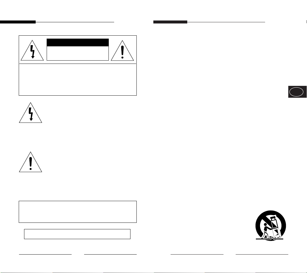
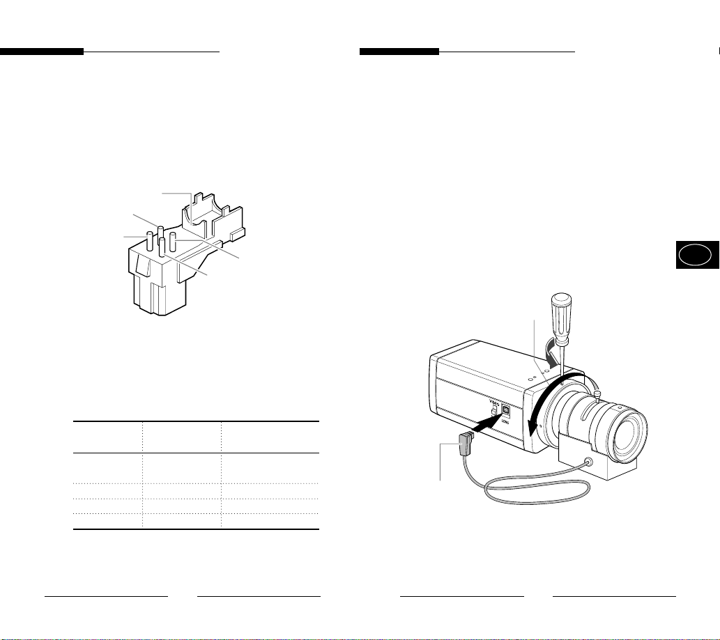
Connecting Auto Iris Lens Connector
Prepare the following Auto Iris Lens Connector supplied
with the camera.
Rib
Pin3
Pin1
Pin4
Pin2
Connect the cable of the control cable, whose covering is
stripped, to the Auto Iris Lens Connector as shown below.
Pin Number DC Control Type Video Control Type
1 Damp(-) Power Source (+9V)
2 Damp(+) Not used
3 Drive(+) Video Signal
4 Drive(-) GND
Mounting the Lens
Loosen a screw fixing the Flange Back Adjustment Ring by
turning it counterclockwise and turn the Adjustment Ring to
the "C" direction (counterclockwise) until it stops. Failure to
do so may result in a damage caused by the bump of the lens
against the image sensor part in the camera when mounting
the lens.
E
C Direction
Auto Iris Control Cable
6
7
Page 7
User Guide
User Guide
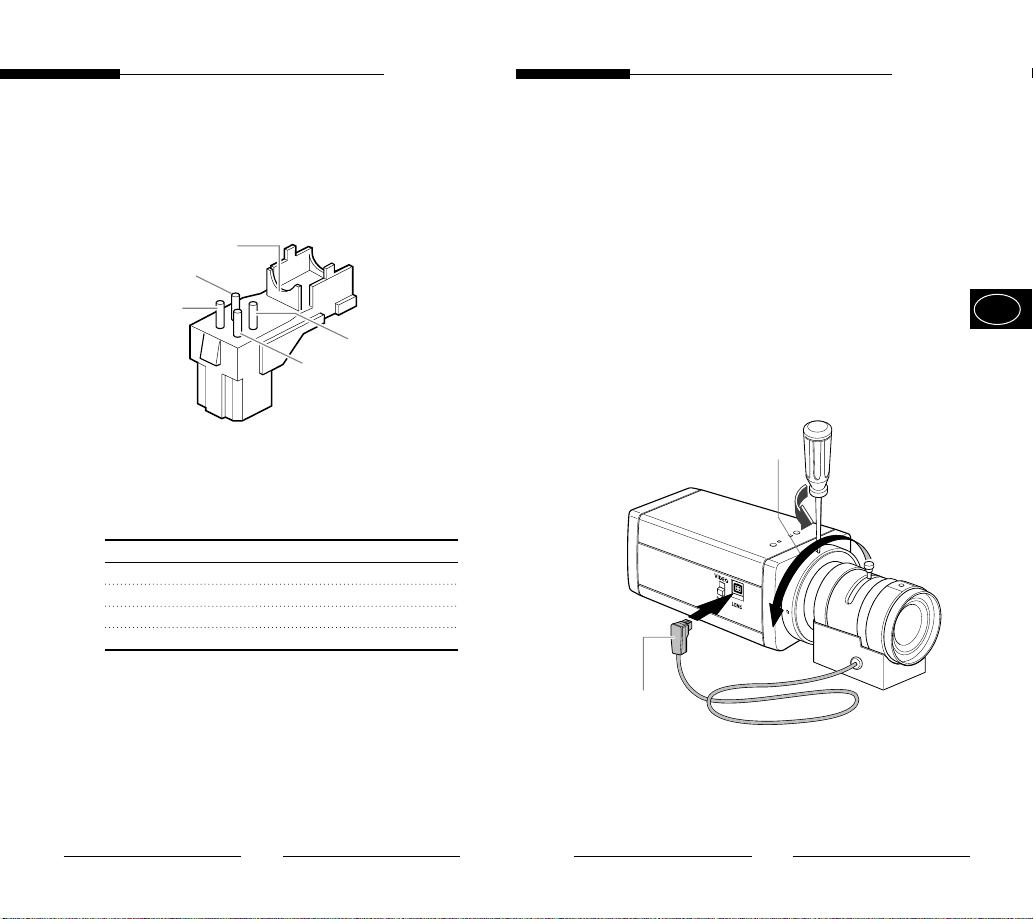
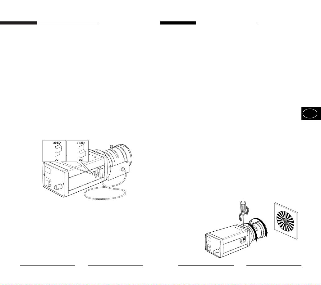
Setting Lens Selection Switch
When lens mounting is completed, set the Lens selection
Switch on the side of the camera according to the mounted
lens type.
When the mounted lens is an Auto Iris Lens of the DC
control type, set the Lens Selection Switch to "DC".
When the mounted lens is an Auto Iris Lens of the Video
control type, set the Lens Selection Switch to "VIDEO".
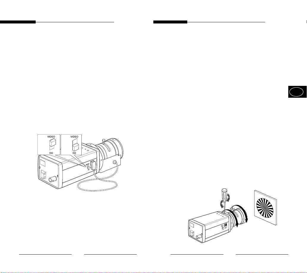
Adjusting Back Focus
Although the Back Focus of the camera has been adjusted
in the factory before its shipment, the focus may not be
accurate for a certain type of the lens. In this case, follow
the procedures below to adjust the Back Focus. First,
following is how to adjust the Back Focus of the Fixed
Focus Lens.
E
① Lightly loosen the screw fixing the Back Focus
Adjustment Ring using a screwdriver.
② Image a vivid subject (with check patterns) at a distance
of more than 10m away and turn the Focus Ring to the
infinity (∞) position.
③ Adjust the Back Focus Adjustment Ring to obtain the
clearest image of the subject.
④ Fasten the screw fixing the Back Focus Adjustment
Ring.
8
9
Page 8

User Guide
User Guide
The following describes how to adjust the Back Focus when
using a Zoom lens.
① Lightly loosen the screw fixing the Back Focus
Adjustment Ring using a screwdriver.
② Image a vivid subject (with check patterns) at a distance
of 3~5m away and adjust the zoom of the lens to TELE
as far as it goes. Then adjust the Focus Ring of the
lens to obtain the clearest image of the subject.
③ Adjust the zoom of the lens to WIDE as far as it goes.
Then turn the Back Focus Ring of the camera to obtain
the clearest image of the subject.
④ Repeat no. ② & ③ 2~3 times to exactly coincide the
zoom focus from TELE and with that from WIDE.
⑤ Fasten the screw fixing the Back Focus Adjustment
Ring.
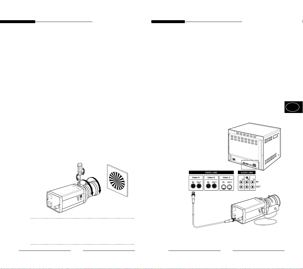
Connecting Cable
After mounting the lens and setting the Lens Selection
Switch, connect the prepared cable to each terminal of the
camera.
① First, connect one end of the BNC cable to the Video
Output Terminal (VIDEO OUT) of the camera.
E
② Then connect the other end of the BNC cable to the
Video Input Terminal of the monitor.
Video In Terminal on the rear of the monitor
Note:
Turning the Back Focus Adjustment Ring to the "C" direction
beyond the adjustable range makes a sound at the limit.
10
BNC Cable
Video Out Terminal
(VIDEO OUT)
11
Page 9
User Guide
User Guide
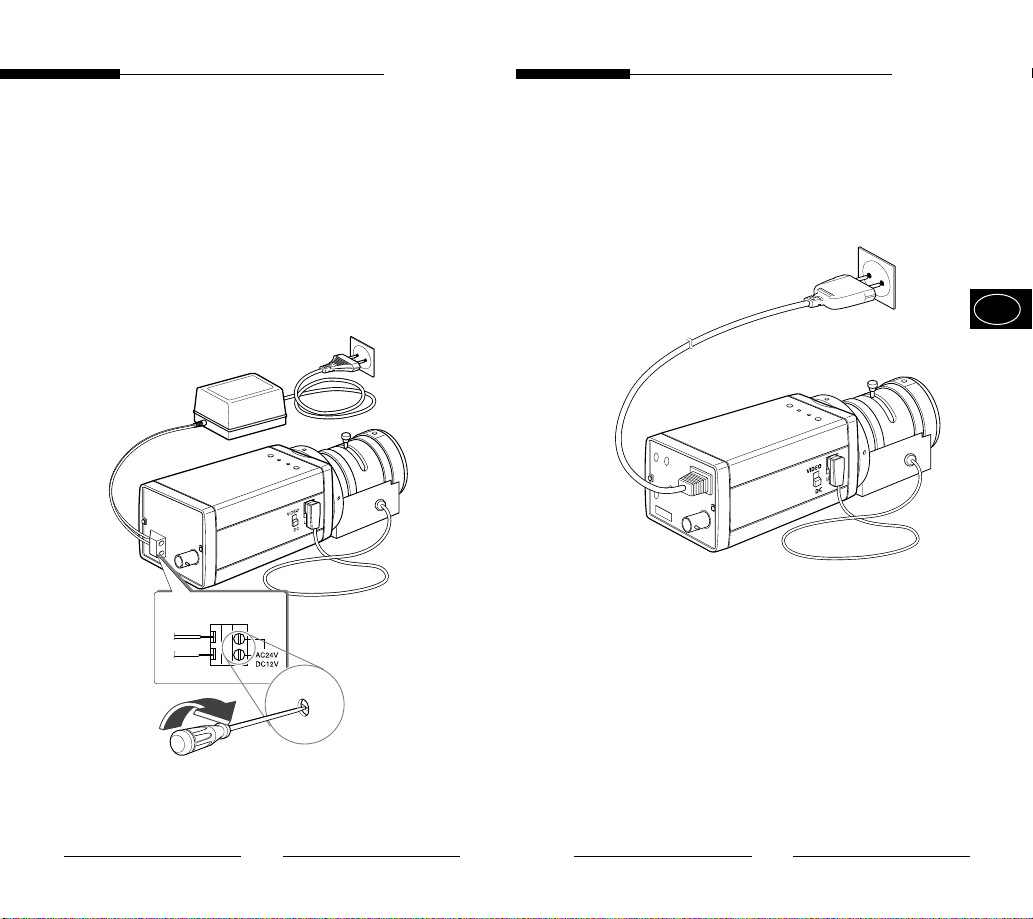
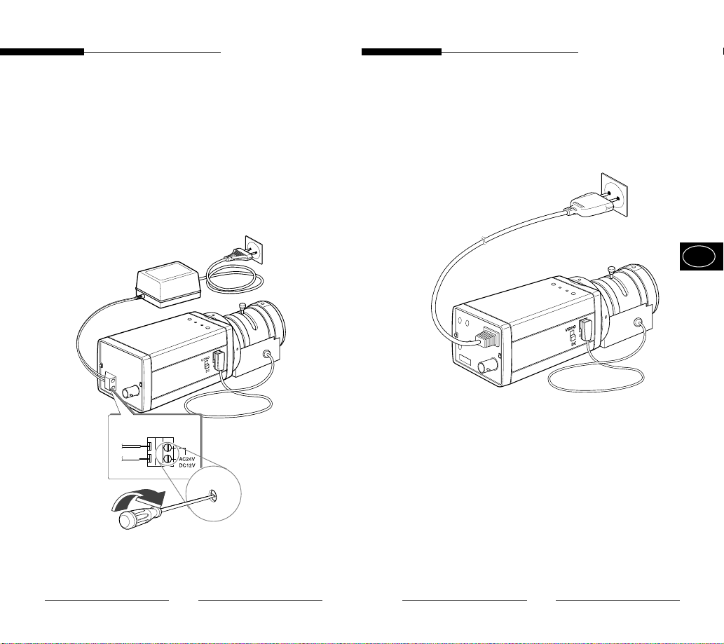
③ AC24V/DC12V Power Input Camera.
Connect 2 lines of the power adapter using a
Phillips screwdriver to the Power IN Terminal of the
camera as shown below.
※ Without the distinction of the polarity, connect to
the AC 24V or AC 12V power source.
AC230V Power Input Camera
Connect the power input cord to the AC 230V power
source.
E
12
13
Page 10
User Guide
User Guide
4. Names and Functions of Parts
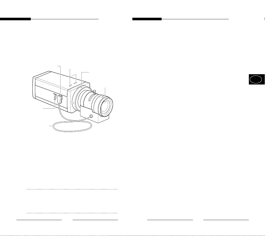
Names and Functions of Parts
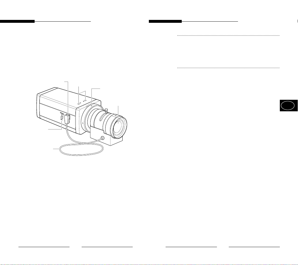
• Side View
# Auto lris Lens Connector
^ ALC Lens Selection
Switch
$ Auto Iris Lens Control
Cable
① Groove for Mount Adapter
Use this groove for fixing the mount adapter to be
connected to the bracket with screws to mount the
camera on the bracket.
② Auto Iris Lens (Option)
Lens to be mounted on the camera
! Groove for Mount Adapter
%
Flange-Back
Adjustment Ring
@ Auto Iris Lens
③ Auto Iris Lens Connector
Used for supplying power, which is required to control
the iris of the lens, as well as control signal, video
signal, or DC signal to the Auto Iris Control Lens.
④ Auto Iris Lens Control Cable
Used for transmitting the control signals to the camera
to control the iris of the lens.
E
⑤ Flange-Back Adjustment Ring
Used for adjusting the Back Focus.
⑥ ALC Lens Selection Switch
Used when selecting the type of Auto Iris Lens to use.
DC : Select this switch to DC when Iris Lens requiring
DC control signal is mounted.
VIDEO : Select this switch to VIDEO when Auto Iris
Lens requiring VIDEO control signal is
mounted.
Note
When the surface of the camera lens is contaminated,
wipe the surface gently with a tissue for lens or a cotton
cloth applied with ethanol.
14
15
Page 11
User Guide
User Guide
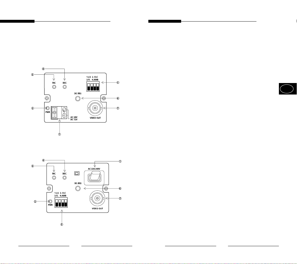
• Rear Panel
AC24V/DC12V Power Input Camera
AC230V Power Input Camera
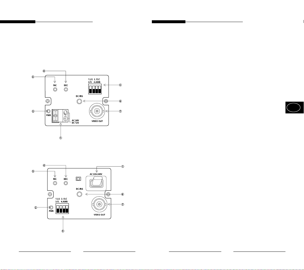
① Power Connection Terminal
Terminal to be connected to the power (adapter) cable
Connect it to AC 24V or DC 12V.
② Power Indication LED
While the power is properly supplied to the camera, the
LED is turned on.
③, ④ INC/DEC Switch
The LINELOCK mode is useful for controlling Vertical
Synchronous Phase.
E
16
17
Page 12
User Guide
User Guide
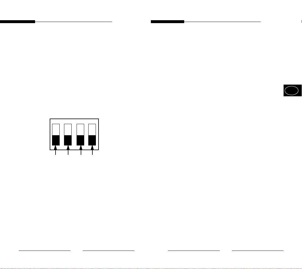
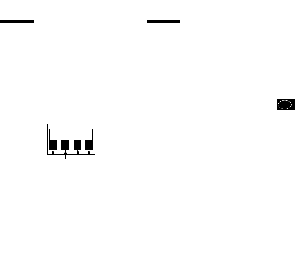
⑤ Function Switches
1) SW1 (LL):
When set to OFF, the camera operates in the Internal
Sync mode. When set to ON, it operates in the Power
Sync mode. If the camera is set to INT (Internal Sync)
when monitoring in the Auto Switching mode with more
than one camera connected to a sequential switcher, etc,
the jump of the screen will occur each time of screen
switching. To switch the screen gently without a jump, set
the camera to LL and adjust the Vertical Sync Phase using
the INC/DEC switch.
1. L/L 2. ELC
3. FL 4. AWB
ON
SW1 SW2 SW3 SW4
2) SW2 (ELC):
Use this switch with the Manual Iris Lens. While this
switch is ON, the speed of the electronic shutter varies
with the brightness of the subject from 1/60 to
1/120,000 sec for automatically controlling the
brightness of the screen. However, with the Auto Iris
Lens (DC or Video Control), be sure to switch OFF.
Color Rolling may occur in this mode.
In that case, input AC power source to the camera and
select SW1 “ON”.
(NTSC : 60HZ, PAL : 50HZ)
3) SW3 (FL):
This is to prevent flicker on the screen when NTSC
system is used in 50HZ power supply region and PAL
system is used in 60HZ power supply region. That is to
prevent shaking on the screen resulted from the
discordance of the vertical sync frequency and the
flicker frequency of the illumination. While this switch is
ON, the electronic shutter is fixed to 1/100sec (NTSC)
or 1/120 sec (PAL).
4) SW4 (AWB ):
When setting up ON, the color of screen is adjusted
automatically in accordance with the change of lighting
color temperature by the change of outer environment.
(ATW) If the lighting condition is steady, OFF setting is
available. The camera memorizes the lighting color
temperature at the time when the switch setting is
changed from ON to OFF, and the camera color is
adjusted to the memorized color temperature. (AWC)
If the lighting color temperature is changed and you
want to make the camera be memorized/operated with
the changed color temperature, re-operate the switch
On/Off operation. However, be aware that an error may
occur under the following conditions.
First, a case that the subject is big, single color of the
high chroma, and in the center of the screen or a
case with almost no white color on the screen
Second, a case with a specific illumination such as a
natrium lamp
※ To adjust the Vertical Sync Phase using the INC/DEC
switch in LL mode, the SW4 must be set to AWB “ON”.
※ For DC 12V, the INT/LL mode is fixed to INT.
E
18
19
Page 13

User Guide
User Guide
⑥ DC Iris Level Control
When the ALC Lens Selection Switch is set to DC, adjust
this Iris Level Control using an adjustment rod such as a
screwdriver.
⑦ Video Output Terminal
This is a terminal to be connected to the Input Terminal
of the monitor. Through this terminal, the video signals
are outputted.
5. Product Specifications
SCC-130B/131B
Item Contents
Product Type CCTV Camera
Broadcasting NTSC STANDARD SYSTEM
System
CCD 1/3” IT type S-HAD CCD
No. of Pixel 130B : 510(H) x 492(V)
131B : 768(H) x 494(V)
Scanning Type 525 Line, 2:1 Interlace
Frequency INTERNAL : 15,734 HZ(H)
59,94 HZ(V)
LINE LOCK :15,750 HZ(H)
60 HZ(V)
Sync Type INTERNAL
LINE LOCK
Resolution 130B : 330TV Lines
131B: 520TV Lines
S/N Ratio 50dB (AGC OFF)
Min. Object 130B : 0.15 Lux (F1.2)
Illumination 131B : 0.3 Lux (F1.2)
(When AC24V power source is used)
E
20
21
Page 14

User Guide
User Guide
ALC /ELC ALC
DC IRIS LENS
VIDEO LENS
ELC
Electronic SHUTTER IRIS function
1/60 to 1/120,000 sec
Color Temperature ATW/AWC Mode
BLC ON(Back Light Compensation)
AGC ON
Video Output COMPOSITE VIDEO OUT
1V p_p 75 Ω/BNC
Power Source AC24V±10%(60Hz±0.3Hz)
DC12V -5% ~ +10%
Power Consumption About 3 Watts
Operating
Temperature
Operating
Humidity
Size 65(W) x 52(H) x 133(L)mm
Weight 450g
-10℃~+50℃
~90%
(BNC included)
SCC-100BP/101BP/130BP/131BP
Item Contents
Product Type CCTV Camera
Broadcasting PAL STANDARD SYSTEM
System
CCD 1/3” IT type S-HAD CCD
No. of Pixel 100BP/130BP : 500(H) x 582(V)
101BP/131BP : 752(H) x 582(V)
Scanning Type 625 Line, 2:1 Interlace
Frequency INTERNAL : 15,625 HZ(H)
50 HZ(V)
LINE LOCK :15,625 HZ(H)
50 HZ(V)
Sync Type INTERNAL
LINE LOCK
Resolution 100BP/130BP : 330TV Lines
131BP/101BP: 520TV Lines
S/N Ratio 50dB (AGC OFF)
Min. Object 100BP/130BP : 0.15 Lux (F1.2)
Illumination 131BP/101BP : 0.3 Lux (F1.2)
(When AC power source is used)
E
22
23
Page 15

User Guide
ALC /ELC ALC
DC IRIS LENS
VIDEO LENS
ELC
Electronic SHUTTER IRIS function
1/60 to 1/120,000 sec
Color Temperature ATW/AWC Mode
BLC ON(Back Light Compensation)
AGC ON
Video Output COMPOSITE VIDEO OUT
1V p_p 75 Ω/BNC
Power Source 100BP/101BP
AC220V~240V(50Hz±0.3Hz)
130BP/131BP
AC24V±10%(50Hz±0.3Hz)
DC12V -5% ~ +10%
Power Consumption 100BP/101BP: About 4 Watts
130BP/131BP: About 3 Watts
Operating
Temperature
Operating
Humidity
Size 65(W) x 52(H) x 133(L)mm
Weight 100BP/101BP : About 550g
-10℃~+50℃
~90%
(BNC included)
130BP/131BP : About 450g
User Guide
E
24
Page 16
Manuel de l’utilisateur
Manuel de l’utilisateur
AVERTISSEMENT
RISQUE DE CHOC ELECTRIQUE,
NE PAS OUVRIR
AVERTISSEMENT : AFIN DE RÉDUIRE LE RISQUE DE CHOC
ELECTRIQUE, NE RETIREZ PAS LE COUVERCLE
(OU L’ARRIÈRE). AUCUNE PIÈCE RÉPARABLE
PAR L’UTILISATEUR À L’INTÉRIEUR. CONFIEZ LA
RÉPARATION À UN PERSONNEL QUALIFIÉ.
L’éclair accompagné d’un symbole en forme
de pointe de flèche dans un triangle
équilatéral, sert à prévenir l’utilisateur qu’il y
a des “tensions dangereuses” non isolées à
l’intérieur de l’appareil, qui peuvent être
suffisamment élevées pour représenter un
risque de choc électrique.
Le point d’exclamation à l’intérieur d’un
triangle équilatéral sert à alerter l’utilisateur
de la présence d’importantes instructions
relatives au fonctionnement et à la
maintenance (réparation) dans la
documentation qui accompagne l’appareil.
ATTENTION: Afin de prevenir des chocs electriques,
ne pas exposer l'appareil à l'hulidité ou a
la pluie.
REMARQUE IMPORTANTE
1. Lisez l’ensemble de ces instructions.
2. Conservez ces instructions en vue d’une future
utilisation.
3. Débranchez cet appareil de la prise de courant
murale avant de le nettoyer.
N’utilisez pas de nettoyant liquide ou en aérosol.
Utilisez un chiffon humide pour le nettoyage.
4. N’utilisez pas de fixations qui ne sont pas
recommandées par le fabriquant, celles-ci
pourraient provoquer des risques.
5. N’utilisez pas cet appareil à proximité d’eau par
exemple, d’une baignoire, d’un lavabo, d’un évier
de cuisine, d’un bac à laver, dans un sous-sol
mouillé, à proximité d’une piscine, etc.
6. Ne disposez pas cet appareil sur un chariot, plan
ou table instable.
L’appareil risque de tomber et provoquer de
sérieuses blessures à un enfant ou un adulte, et
pourrait être endommagé.
N’utilisez qu’avec un chariot ou plan recommandé
par le fabriquant et utilisez un kit de montage
agréé par le fabriquant.
Un ensemble appareil et chariot doit être déplacé
avec précaution. Les arrêts
rapides, une force excessive
ainsi que des surfaces
irrégulières risque de provoquer
un renversement de l’appareil et
du chariot.
F
ii
iii
Page 17

Manuel de l’utilisateur
Manuel de l’utilisateur
7. Les emplacements et les ouvertures à l’arrière et
au bas de l’armoire sont prévus pour la ventilation,
afin d’assurer un fonctionnement fiable de
l’appareil et d’éviter la surchauffe.
Ces ouvertures ne doivent jamais être bloquées,
en plaçant l’appareil sur un lit, un canapé, un tapis
ou d’autres surfaces identiques. Il convient de ne
jamais placer cet appareil à proximité ou sur un
radiateur ou un générateur de chaleur.
Cet appareil ne doit pas être placé dans une
installation intégrée comme par exemple une
bibliothèque, à moins qu’il n’y ait une ventilation
adaptée.
8. Il convient de ne faire fonctionner cet appareil qu’à
partir du type de source d’alimentation indiqué sur
l’étiquette. Si vous n’êtes pas sûr du type
d’alimentation de votre maison, consultez votre
revendeur ou l’entreprise d’électricité locale.
9. Ne laissez rien sur le cordon d’alimentation. Ne
placez pas cet appareil dans un endroit où le
cordon risque d’être piétiné.
10. Ne surchargez pas les prises de courant murales
et les rallonges électriques, cela pourrait
occasionner un incendie ou un choc électrique.
11. Suivez tous les avertissements et toutes les
instructions spécifiés sur l’appareil.
12. Ne tentez pas de réparer cet appareil vous-
même. L’ouverture ou le retrait des couvercles
peut vous exposer à des tensions dangereuses
ou d’autres risques. Faites appel à un personnel
qualifié pour toute opération de réparation.
13. Débranchez l’appareil de la prise murale et
adressez-vous à un personnel qualifié pour les
réparations dans les cas suivants :
a. Lorsque le cordon d’alimentation ou la prise est
endommagé ou effiloché.
b. Si du liquide a pénétré dans l’appareil.
c. Si l’appareil ne fonctionne pas normalement en
suivant les instructions relatives au fonctionnement.
Ne réglez que les commandes dont il est question
dans les instructions relatives au fonctionnement. Un
mauvais réglage d’autres commandes risquerait de
provoquer des dommages et demanderait un travail
important de la part d’un technicien pour obtenir un
fonctionnement normal.
d. Si l’appareil a été exposé à la pluie ou à l’eau.
e. Si l’appareil est tombé ou si l’armoire a été
endommagée.
f. Lorsque l’appareil présente un net changement au
niveau de ses performances cela indique qu’il
convient de le faire réparer.
14. Lorsqu’il est nécessaire de changer des pièces,
assurez-vous que le technicien a utilisé des
pièces de rechange recommandées par le
fabriquant qui présentent les mêmes
caractéristiques que la pièce d’origine.
Des remplacements non autorisés peuvent
provoquer un incendie, un choc électrique, ou
d’autres dangers.
15. Après un dépannage ou une réparation de
l’appareil, demandez au technicien d’effectuer les
vérifications de sécurité courantes afin d’établir
que l’appareil est en bon état de fonctionnement.
F
iv
v
Page 18

Manuel de l’utilisateur
Manuel de l’utilisateur
Contenu
1. Introduction
2. Caractéristiques
3. Installation
Précautions d’installation et d’utilisation
Branchement du connecteur de l’objectif du
diaphragme automatique
Montage de l’objectif
Paramétrage du sélecteur de l’objectif
Réglage de la mise au point arrière
Câble de connexion
4. Noms et fonction des pièces
Vue latérale
Panneau arrière
5. Caractéristiques du produit .........................
..............................................................
......................................................
................................................................
..........................................
................................................
...............................................
.................................. 14
...............................................................
......................................................
.............
................
.....................
11
14
16
21
1. Introduction
3
4
5
5
6
7
8
9
Avec un Super -HAD CCD tout récent, ces caméras
offrent les meilleures fonctions de surveillance en
connexion avec le système CCTV.
❈ Si vous installez un diaphragme manuel et activez le
bouton de fonction ELC dans un environnement
avec un éclairage fluorescent, la couleur risque de
tourner.
Dans ce cas, sélectionnez l’alimentation CA avant
d’activer bouton de fonction L/L.
(NTSC : 60 Hz, PAL : 50 Hz)
☞
L’ondulation de couleur est un phénomène de
changement non périodique de la couleur sur l’écran
du moniteur.
Ceci arrive lorsque la Balance des Blancs n’est pas
fixée à cause d’une vacillation d’un éclairage
mécanique fluorescent et que son cycle est identique
à celui de la fréquence d’alimentation.
F
2
3
Page 19

Manuel de l’utilisateur
Manuel de l’utilisateur
2. Caractéristiques
Sensibilité élevée
Grâce à l’appareil aérothermique CCD Super 1/3" et
son objectif micropuce intégré dernier cri, on obtient
une sensibilité élevée.
Excellente compensation de contre-jour
Malgré la présence d’un éclairage intense ou d’un
rayonnement du soleil derrière le sujet, vous pouvez
obtenir une image nette grâce à une combinaison
idéale de l’excellente fonction de compression
d’éclairage intense (Compensation KNEE) et de la
fonction BLC (Back Light Compensation : Correction
du contre-jour)
Verrouillage de la ligne numérique
La commande ainsi que la fiabilité ont été
améliorées grâce au verrouillage complet de la ligne
numérique, ce qui permet aux utilisateurs de régler
la phase de synchronisation de la ligne.
Résolution
La haute résolution est réalisée grâce au processus
d’image ‘Full Digital’ par le DSP à partir de la caméra de
surveillance.
3. Installation
Précautions d’installation et d’utilisation
➀ N’essayez pas de démonter la caméra
vous-même.
➁ Soyez vigilant lors de la manipulation de la
caméra. Evitez de la cogner ou de la secouer.
Faites attention aux dommages qui pourraient
être occasionnés suite à un rangement ou un
fonctionnement inadapté.
➂ N’exposez pas cette caméra à la pluie ou à
l’humidité.
Ne faites pas fonctionner cette caméra dans un
endroit mouillé.
➃ N’utilisez aucun détergent fort ou abrasif lorsque
vous nettoyez le corps de la caméra.
Nettoyez-la à l’aide d’un chiffon sec.
➄ Gardez la caméra dans un endroit frais à l’abri
du soleil. La laissez exposée au soleil peut
provoquer un mauvais fonctionnement de
l’appareil.
F
4
5
Page 20
Manuel de l’utilisateur
Manuel de l’utilisateur
Branchement du connecteur de l’objectif
du diaphragme automatique
Préparez le connecteur (indiqué ci-après) de
l’objectif du diaphragme automatique fourni avec la
caméra.
Rib
Broche 3
Broche 1
Broche 4
Broche 2
Branchez le câble du câble de contrôle, celui dont la
gaine est dénudée, au connecteur de l’objectif du
diaphragme automatique comme indiqué ci-après.
Numéro de Type de Type de
la broche commande DC commande vidéo
1 Damp(-)
2 Damp(+) Non utilisé
3 Drive(+) Signal vidéo
4 Drive(-) Terre
Source d’alimentation
(+ 9 V)
Montage de l’objectif
Desserrez la vis fixant la bague de réglage de la
face d’appui en la tournant dans le sens inverse des
aiguilles d’une montre et tournez la bague de
réglage dans la direction "C" (sens inverse des
aiguilles d’une montre) jusqu’à ce qu’elle s’arrête.
Le non-respect de cette procédure peut causer un
dommage dû à un choc de l’objectif contre le
capteur d’image dans la caméra lors du montage
de l’objectif.
Direction de C
Diaphragme
automatique
Câble de
commande
F
6
7
Page 21
Manuel de l’utilisateur
Manuel de l’utilisateur
Paramétrage du sélecteur de l’objectif
Après avoir placé l’objectif, paramétrez le sélecteur
de l’objectif situé à l’arrière de la caméra selon le
type d’objectif installé.
Si l’objectif installé est un objectif à diaphragme
automatique de type de commande DC, paramétrez
le sélecteur de l’objectif sur "DC". Si l’objectif installé
est un objectif à diaphragme automatique de type
de commande Vidéo, paramétrez le sélecteur de
l’objectif sur "VIDEO".
Réglage de la mise au point arrière
Bien que la mise au point arrière ait été réglée en
usine avant l’expédition de l’appareil, la mise au
point peut ne pas être précise pour un certain type
d’objectif.
Dans ce cas, suivez la procédure décrite ci-après
afin de régler la mise au point arrière. Vous
trouverez ci-après une explication concernant la
manière de régler la mise au point arrière de
l’objectif à focale fixe.
➀ Desserrez doucement la vis de fixation de la
bague de réglage de la mise au point arrière
à l’aide d’un tournevis.
➁ Vissez un sujet vivace (avec des échantillons de
contrôle) placé à une distance de plus de 10 m
et tournez la bague de mise au point vers la
position infini (∞).
➂ Réglez la bague de réglage de la mise au point
arrière afin d’obtenir l’image la plus nette
possible du sujet.
➃ Resserrez la vis fixant la bague de réglage de la
mise au point arrière.
F
8
9
Page 22
Manuel de l’utilisateur
Manuel de l’utilisateur
Le paragraphe suivant explique comment régler la
mise au point arrière lorsque vous utilisez le zoom.
➀ Dévissez doucement la vis fixant la bague de
réglage de la mise au point arrière à l’aide d’un
tournevis.
➁ Vissez un sujet vivace (avec des échantillons de
contrôle) à une distance de 3 à 5 m et réglez le
zoom de l’objectif sur TELE le plus loin possible.
Réglez ensuite la bague de mise au point de
l’objectif afin d’obtenir une image la plus nette
possible.
➂ Réglez le zoom de l’objectif sur WIDE aussi loin
que possible. Tournez ensuite la bague de mise
au point arrière de l’appareil afin d’obtenir l’image
la plus nette possible du sujet.
➃ Renouvelez les opérations n ➁ & ➂ 2 à 3 fois
afin que la mise au point du zoom de TELE
coïncide exactement avec celle de WIDE.
➄ Resserrez la vis en fixant la bague de réglage de
la mise au point arrière.
Câble de connexion
Après avoir placé l’objectif et paramétré le sélecteur
de l’objectif, branchez le câble préparé à chaque
borne de la caméra.
➀ Branchez tout d’abord un côté du câble BNC sur
la borne sortie vidéo (VIDEO OUT) de la caméra.
➁ Branchez ensuite l’autre extrémité du câble
BNC sur la borne entrée vidéo du moniteur.
F
Borne entrée vidéo à l’arrière du moniteur
Remarque :
Au moment de tourner la bague de réglage de la mise au point
arrière dans la direction de "C" au-delà de la limite de réglage,
vous entendrez un signal sonore à cette limite.
10
Câble BNC
Borne sortie vidéo
(VIDEO OUT)
11
Page 23
Manuel de l’utilisateur
Manuel de l’utilisateur
➂ Caméra avec entrée CA 24V / CC12V.
Branchez 2 lignes de l’adaptateur de courant à
l’aide d’un tournevis Phillips sur la borne Power
IN de l’appareil comme indiqué ci-après.
※ Sans distinction de polarité, branchez sur la
source d’alimentation CA 24V ou CA 12V.
Caméra avec entrée CA 230V
Branchez le cordon d’alimentation à la source
d’alimentation CA 230V.
F
12
13
Page 24
Manuel de l’utilisateur
Manuel de l’utilisateur
4. Noms et fonction des pièces
Noms et fonction des pièces
• Vue latérale
# Connecteur pour objectif à
diaphragme automatique
^ Sélecteur de
l’objectif ALC
$ Câble de commande pour
objectif à diaphragme
automatique
①
Cannelure pour le connecteur de
montage
Utilisez cette cannelure afin de fixer le
connecteur de montage qui doit être connecté à
la griffe à l’aide de vis servant à monter la
caméra sur la griffe.
②
Objectif à diaphragme automatique
(Option)
Objectif à installer sur la caméra.
! Cannelure pour le connecteur
de montage
% Bague de réglage
de la face d’appui
@ Objectif à diaphragme
automatique
14
Remarque:
Lorsque la surface de l’objectif de la caméra est
sale, essuyez-la doucement à l’aide d’un chiffon
pour objectif ou un chiffon en coton imbibé
d’éthanol.
③
Connecteur pour objectif à diaphragme
automatique
Est utilisé pour l’alimentation, nécessaire au
contrôle du diaphragme de l’objectif, mais
également au signal de commande, au signal
vidéo, ou signal DC vers l’objectif de commande
à diaphragme automatique.
④
Câble de commande pour objectif à
diaphragme automatique
Est utilisé pour la transmission des signaux de
commande à la caméra afin de contrôler le
diaphragme de l’objectif.
⑤
Bague de réglage de la face d’appui
Est utilisé afin de régler la mise au point arrière.
⑥
Sélecteur de l’objectif ALC
Est utilisé au moment de sélectionner le type
d’objectif à diaphragme automatique à utiliser.
DC : Placez-le sur DC lorsqu’un objectif à
diaphragme nécessitant un signal de
commande DC est installé.
VIDEO: Placez-le sur VIDEO lorsqu’un objectif à
diaphragme automatique nécessitant un
signal de commande VIDEO est installé.
15
F
Page 25
• Panneau arrière
Caméra avec entrée CA 24V / CC 12V
Caméra avec entrée CA 230V
Manuel de l’utilisateur
Manuel de l’utilisateur
①
Borne de connexion
Borne à brancher sur le câble d’alimentation
(adaptateur) - Branchez-le sur le CA 24V ou le
CC 12V.
②
Voyant d’indication d’alimentation
Lorsque la caméra est sous tension, le voyant
est allumé.
③, ④ Boutons INC/DEC
Le mode LINELOCK est utilisé pour contrôler la Phase
Verticale Synchrone.
F
16
17
Page 26
Manuel de l’utilisateur
Manuel de l’utilisateur
⑤
Sélecteurs de fonction
1) SW1 (LL):
Lorsque ce bouton est réglé sur OFF, la caméra
fonctionne en mode de Synchronisation Interne. Lorsqu’il
est réglé sur ON, la caméra fonctionne en mode de
Synchronisation d’Alimentation. Si la caméra est réglée
sur INT (Synchronisation Interne) lors d’une surveillance
en mode Auto Switching (Basculement automatique) avec
plusieurs caméras connectées à l’interrupteur séquentiel,
etc., un saut d’écran sera provoqué à chaque
basculement d’écran. Pour basculer l’écran sans saut,
réglez la caméra sur LL et ajustez la Phase de
Synchronisation Verticale avec les boutons INC/DEC.
1. L/L 2. ELC
3. FL 4. AWB
ON
SW1 SW2 SW3 SW4
2) SW2 (ELC):
Utilisez cet interrupteur avec l’objectif à diaphragme
manuel. Lorsqu’il est sur ON, la vitesse de
l’obturateur électronique varie en fonction de la
luminosité du sujet de 1/60 à 1/120,000 sec afin de
contrôler automatiquement la luminosité de l’écran.
Cependant, avec l’objectif à diaphragme
automatique (DC ou commande vidéo), assurezvous de le positionner sur OFF.
couleur peut apparaître dans ce mode. Dans ce cas,
mettez la tension CA et positionnez le SW1 sur ‘ON’.
(NTSC : 60HZ, PAL : 50HZ)
L’ondulation de
18
3) SW3 (FL):
Ce bouton est utilisé pour éviter la vacillation de l’écran
lorsque le système NTSC est utilisé avec une
alimentation 50HZ ou lorsque le système PAL est utilisé
avec une alimentation 60HZ. Ceci permet d’empêcher
les secousses à l’écran dues à la discordance entre la
fréquence de synchronisation verticale et la fréquence
de vacillation de l’éclairage. Lorsque ce bouton est
positionné sur ON, l’obturateur électrique est fixé sur
1/100sec (NTSC) ou 1/120 sec (PAL).
4) SW4 (AWB ):
Lorsque vous sélectionnez ON, la couleur d’écran est
automatiquement ajustée suivant la température de
couleur de l’éclairage qui varie selon l’environnement
extérieur. (ATW) Si les conditions d’éclairage sont
constantes, vous pouvez sélectionnez OFF.
La caméra mémorise la température de couleur de
l’éclairage au moment du basculement du bouton (ON>OFF) et la couleur de la caméra est ajustée avec la
température de couleur mémorisée. (AWC) Si la
température de couleur de l’éclairage change et que
vous désirez mémoriser/régler la caméra avec la
température modifiée, réglez à nouveau le bouton
ON/OFF.
Cependant, sachez qu’une erreur peut survenir
dans les conditions suivantes :
1. Le sujet est grand, d’une couleur unique et intense et il
est placé au centre de l’écran, ou bien il n’y a
pratiquement aucune couleur blanche à l’écran.
2. Avec un éclairage spécifique tel qu’une lampe au
sodium.
※ Pour ajuster la Phase de Synchronisation Verticale
sur le mode LL en utilisant le bouton INC/DEC, le
bouton SW4 doit être réglé sur AWB ‘ON’.
※ Pour CC 12V, le mode INT/LL est fixé sur INT.
19
F
Page 27

Manuel de l’utilisateur
⑥
Commande du niveau du diaphragme DC
Lorsque le sélecteur de l’objectif ALC est
paramétré sur DC, réglez cette commande de
niveau de l’objectif à l’aide d’une tige de réglage
comme un tournevis.
⑦
Borne de sortie vidéo
Il s’agit d’une borne à connecter à la borne
d’entrée du moniteur. Grâce à cette borne les
signaux vidéo sont des sorties.
Manuel de l’utilisateur
5.
Caractéristiques du produit
SCC-130B/131B
Article Contenu
Type de produit CCTV Camera
Système d’émission Système NTSC Standard
CCD 1/3” IT type S-HAD CCD
Nombre de pixels 130B : 510(H) x 492(V)
131B : 768(H) x 494(V)
Type de balayage 525 Line, 2:1 Entrelacement
Fréquence INTERNE : 15,734 HZ(H)
59,94 HZ(V)
VERROUILLAGE DE LA LIGNE
:15,750 HZ(H)
60 HZ(V)
Sync Type INTERNE
VERROUILLAGE DE LA LIGNE
(Dans le cas d’une alimentation CA 24V)
Résolution 130B : 330 Lignes TV
131B : 520 Lignes TV
Taux S/N 50dB (CAG OFF)
Illumination 130BP : 0.15 Lux (F1.2)
minimum de l’objet 131BP : 0.3 Lux (F1.2)
F
20
21
Page 28

Manuel de l’utilisateur
Manuel de l’utilisateur
ALC /ELC ALC
OBJECTIF A DIAPHRAGME DC
OBJECTIF VIDEO
ELC
Fonction OBTURATEUR DE
DIAPHRAGME électronique
1/60 à 1/120,000 sec
Température de couleur
BLC ON(Compensation du contre-jour)
AGC ON
Sortie vidéo SORTIE VIDEO COMPOSITE
Source AC 24V±10%(60Hz±0.3Hz)
d’alimentation DC12V-5% ~ +10%
Consommation Environ 3 Watts
Température de -10℃~+50℃
fonctionnement
Humidité de
fonctionnement
Taille 65(W) x 52(H) x 133(L)mm
Poids Environ 450g
Mode ATW/AWC
1V p_p 75 Ω/BNC
~90%
(BNC inclus)
SCC-100BP/101BP/130BP/131BP
Article Contenu
Type de produit CCTV Camera
Système d’émission Système PAL Standard
CCD 1/3” IT type S-HAD CCD
Nombre de pixels 100BP/130BP : 500(H) x 582(V)
101BP/131BP : 752(H) x 582(V)
Type de balayage 625 Line, 2:1 Entrelacement
Fréquence
Sync Type INTERNE
Résolution 100BP/130BP : 330 TV Lines
Taux S/N 50dB (CAG OFF)
Illumination 100BP/130BP : 0.15 Lux (F1.2)
minimum de l’objet 131BP/101BP : 0.3 Lux (F1.2)
INTERNE : 15,625 HZ(H)
50 HZ(V)
VERROUILLAGE DE LA LIGNE
:15,625 HZ(H)
50 HZ(V)
VERROUILLAGE DE LA LIGNE
(Dans le cas d’une source d’alimentation CA)
131BP/101BP : 520 TV Lines
F
22
23
Page 29

Manuel de l’utilisateur
ALC /ELC ALC
OBJECTIF A DIAPHRAGME DC
OBJECTIF VIDEO
ELC
Fonction OBTURATEUR DE
DIAPHRAGME électronique
1/60 à 1/120,000 sec
Température de couleur
BLC ON(Compensation du contre-jour)
AGC ON
Sortie vidéo SORTIE VIDEO COMPOSITE
Source 100BP/101BP
d’alimentation
Consommation 100BP/101BP: Environ 4 Watts
Température de -10℃~+50℃
fonctionnement
Humidité de
fonctionnement
Taille 65(W) x 52(H) x 133(L)mm
Poids 100BP/101BP : Environ 550g
Mode ATW/AWC
1V p_p 75 Ω/BNC
AC 220V~240V(50Hz±0.3Hz)
130BP/131BP
AC 24V±10%(50Hz±0.3Hz)
DC12V-5% ~ +10%
130BP/131BP: Environ 3 Watts
~90%
(BNC inclus)
100BP/101BP : Environ 450g
Manuel de l’utilisateur
F
24
Page 30

Benutzerhandbuch
Benutzerhandbuch
ACHTUNG !
HOCHSPANNUNGSGEFA
HRNICHT ÖFFNEN!
Warnung: Verhindern Sie einen möglichen
Elektroschlag,indem Sie die Abdeckung nicht
entfernen. Wenden Sie sich bei der Wartung an
dafür qualifiziertes Personal.
Blitzzeichen: Dieses Zeichen weist den
Benutzer auf die nicht isolierte
Hochspannung innerhalb der Anlage hin.
Es besteht die Gefahr eines
Elektroschlages.
Ausrufezeichen: Dieses Zeichen ist dazu
da, den Benutzer auf wichtige
Inbetriebnahme- und
Instandhaltungsvorschriften hinzuweisen,
die dem Gerät in Form einer Broschüre
beigelegt sind.
Warnung: Um das Risiko von Feuer oder Elektroschlag zu
vermeiden, darf weder das Gerät selbst, noch das
Netzteil Regen oder Feuchtigkeit ausgesetzt
werden.
IMPORTANT SAFEGUARDS
1. Bitte lesen Sie die Bedienungsanleitung
2. Die Bedienungsanleitung muss zur späteren
Verwendung behalten werden.
3. Vor der Reinigung muss man das Gerät von der
Steckdose trennen. Bitte kein flüssiges
Reinigungsmittel oder Aerosol verwenden. Nur
mit einem feuchten Tuch reinigen.
4. Verwenden Sie keine Zusatzgeräte, die nicht vom
Gerätehersteller empfohlen werden, da diese
einen Elektroschlag verursachen können.
5. Dieses Gerät nicht in der Nähe von Wasser
verwenden, z.B. in der Nähe von einer
Badewanne, einem Waschbecken oder einem
Ausguss, in einem nassen Kellergeschoss oder
in der Nähe von einem Schwimmbad.
6. Dieses Gerät nicht auf einem instabilen Träger,
Ständer oder Tisch betreiben. Es besteht die
Gefahr, dass das Gerät herunterfällt und nicht nur
Kinder, sondern auch Erwachsene schwer
verletzt. Auch das Gerät kann dabei schwer
beschädigt werden. Verwenden Sie nur Träger
oder Ständer die vom Gerätehersteller empfohlen
werden, und benutzten Sie die dafür
vorgesehenen Befestigungspunkte des
Geräteherstellers. Transportieren Sie das Gerät
vorsichtig. Vermeiden Sie
ruckartige Bewegungen und
Erschütterungen, um das
Gerät zu schützen.appliance
and cart combination to
overturn.
G
ii
iii
Page 31

Benutzerhandbuch
Benutzerhandbuch
7. Weil die Schlitze und Öffnungen im Gehäuse an
der Rück- oder Unterseite Ventilationen
ermöglichen, eine zuverlässige Bedienung des
Gerätes sichern und das Gerät vor einer
Überhitzung schützen, dürfen sie auf keinen Fall
versperrt werden, in dem man das Gerät auf einem
Bett, Sofa, Teppich oder auf ähnlichen Unterlagen
aufstellt. Dieses Gerät darf auf keinen Fall in der
Nähe von Heizkörpern bzw. auf einem Heizkörper
verwendet werden. Es darf nicht auf eingebauten
Einrichtungen wie Bücherregal oder Gestell
betrieben werden, wenn keine richtige Ventilation
stattfindet.
8. Dieses Gerät darf nur mit der auf dem Gerät
angegebenen Betriebsspannung betrieben
werden. Um vor der Verwendung die
Betriebsspannung des Gerätes sicherzustellen,
wenden Sie sich an ihren Händler oder an eine
Stromversorgungsfirma.
9. Die Stromkabel müssen so gelegt werden, dass
keiner auf diese treten oder sie einklemmen kann.
Sonst kann es zur Störung der Betriebsspannung
kommen.
10. Überlasten Sie nicht die Steckdose und das
Verlängerungskabel. Es besteht die Gefahr, dass
dadurch Feuer oder Elektroschlag verursacht wird.
11. Alle Warnungen, die auf dem Gerät und in der
Bedienungsanleitung angegeben werden, müssen
beachtet werden.
12. Versuchen Sie nicht die Abdeckung des Gerätes zu
entfernen oder zu öffnen und das Gerät selbst zu
reparieren. Dadurch können Sie der gefährlichen
Hochspannung oder anderen Elektroschlägen
ausgesetzt werden. Bitte wenden Sie sich an
qualifiziertes Personal beim Kundendienst.
13. Sollten folgende Probleme auftreten, ziehen Sie den
Netzstecker und wenden Sie sich an den
Kundendienst:
a. Wenn das Netzkabel oder der Netzstecker beschädigt
worden ist.
b. Wenn Flüssigkeiten in das Gerät gelangt sind.
c. Wenn das Gerät nicht wie in der Bedienungsanleitung
beschrieben funktioniert. Sie sollten das Gerät einstellen
wie es in der Bedienungsanweisung beschrieben ist.
Sonst kann das Gerät beschädigt werden.
d. Wenn das Gerät Regen oder Wasser ausgesetzt war.
e. Wenn das Gerät gestürzt ist oder das Gehäuse
beschädigt ist.
f. Wenn das Gerät beim Betrieb eine deutliche
Veränderung zeigt.
G
14. Sie müssen darauf achten, dass der
Reparaturservice nur Ersatzteile benutzt, die vom
Gerätehersteller freigegeben wurden.
15. Bitten Sie das Servicepersonal beim Kundendienst
um die Sicherheitskontrolle, um festzustellen, dass
sich das Gerät in einem einwandfreien Zustand
befindet.
iv
v
Page 32

Benutzerhandbuch
Benutzerhandbuch
Inhalt
1. Einleitung
2. Produktmerkmale
3. Installation
Vorkehrungen bei der Installation und Verwendung
Anschluss eines Auto-Iris-Objektives
Objektivmontage
Auswahlschalter für die Objektiveinstellung
Anpassung des Auflagemaßes...................................... 9
Kabelverbindungen
4. Namen und Funktion der Teile
Seitenansicht
Rückansicht (Funktionsschalter)
5. Technische Daten
.......................................................................
.........................................................
.....................................................................
................................
............................................................
.....................................................
................................
................................................................
...................................
......................................................
...
.................
11
14
14
16
21
1. Einleitung
3
4
5
5
6
7
8
Diese Fernseh-Überwachungskamera verwendet den
modernsten Super-HAD-CCD-Sensor für eine optimale
Leistung
❈ Im mechanischen Leuchtstofflicht Umgebug, wenn Sie
MANUELLE BLENDE anbringen und den ELC
Schalter unter FUNKTION Schaltern einschalten,
kann Farbe gerollt werden.
In diesem Fall schaltet Versorgung AC Power ein,
bevor Sie L/L Schalter unter FUNKTION einschalten.
(NTSC:60HZ , PAL:50HZ)
☞
Farbflackern bedeutet, dass die Farbdarstellung auf
dem Monitor nicht konstant ist. Dieser Effekt entsteht
durch einen schnell wechselnden Weißabgleich,
hervorgerufen durch die in der gleichen Frequenz wie
die Spannungsversorgung der Kamera pulsierenden
Beleuchtung.
G
2
3
Page 33

Benutzerhandbuch
Benutzerhandbuch
2. Produktmerkmale
Hohe Lichtempfindlichkeit
Durch den eingebauten 1/3 ” Super HAD CCD- Sensor mit
integrierten Mikrolinsen wird eine hohe Lichtempfindlichkeit
der Kamera realisiert.
Exzellente Gegenlichtkompensation
Wenn eine starke Beleuchtungsquelle oder Sonnenlicht sich
hinter dem Gegenstand befindet, wird durch die
Gegenlichtkompensation eine ideale Kombination gesucht,
um ein klares und gutes Ergebnis zu erzielen. Dieses
geschieht durch eine Aufteilung des Bildes in 5 Blöcke die in
der Kamera fest definiert sind.
Digitale Line-lock- Synchronisation
Die Kontrolle und Zuverlässigkeit der digitalen Line-Lock
Synchronisation wurde verbessert. Der Anwender kann
die Phase individuell einstellen.
Auflösung
Durch die voll-digitale Bildverarbeitung für
Überwachungskameras werden hohe Auflösungen
gewährleistet.
3. Installation
Vorkehrungen bei der Installation und
Verwendung
① Auf keinen Fall versuchen, die Kamera selber zu
zerlegen.
② Vorsichtig mit dem Umgang der Kamera. Verhindern
Sie das Herunterfallen oder Schütteln der Kamera.
Vermeiden Sie das Beschädigen der Kamera durch
unsachgemäße Behandlung oder Lagerung da sonst
nicht die volle Funktion gewährleistet ist.
③ Die Kamera auf keinem Fall Regen oder Feuchtigkeit
aussetzten und nicht an nassen Plätzen verwenden.
④ Keine scharfen Reinigungsmittel zum Säubern der
Kamera verwenden. Zum Reinigen der Kamera nur
trockene Tücher verwenden.
⑤ Stellen sie die Kamera an einen geeigneten Platz.
Nicht unter direkter Sonneneinstrahlung verwenden.
G
4
5
Page 34

Benutzerhandbuch
Benutzerhandbuch
Vorbereitung des mitgelieferten
Objektivsteckers für die Kamera.
Bereiten Sie den mitgelieferten Objektivstecker für das
Anlöten des Objektivkabels vor
Rib
Pin3
Pin1
Pin4
Pin2
Verbinden Sie die einzelnen Kabel mit dem
Objektivstecker wie unten in der Tabelle beschrieben.
Pin No DC-gesteuerte Blende ES- gesteuerte Blende
1 Bremsspule (-) Spannung (+9V)
2 Bremsspule (+) nicht belegt
3 Treiberspule (+) Videosignal
4 Treiberspule (-) Masse
Einstellen des Objektivs
Lösen Sie die Feststellschraube gegen den Uhrzeigersinn an
dem Einstellring. Drehen Sie jetzt den Einstellring auf die
Position “C” bis es nicht mehr weiter geht. Sonst kann es zur
Beschädigung des Objektivs oder des Bildsensors kommen.
C Anweisung
Automatischer verschluß
Objektiv Arschluß
G
6
7
Page 35

Benutzerhandbuch
Benutzerhandbuch
Auswahlschalter für die Objektiveinstellung
Wenn die Montage des Objektivs abgeschlossen ist,
müssen Sie an der rechten Seite der Kamera den
Objektivtyp mit einem Schalter einstellen.
Wenn das Objektiv über eine DC- geregelte Blende
verfügt, stellen Sie den Schalter auf “DC”. Wenn das
Objektiv mit einer ES- geregelten Blende ausgestattet ist,
stellen Sie den Schalter auf “VIDEO”.
Einstellung des Auflagemaßes
Grundsätzlich unterscheidet man zwei verschiedene Arten
von Objektiven.
Zum einen das C- Mount Objektiv und zum anderen das
CS- Objektiv. Bei einem C- Mount Objektiv, dreht man den
Einstellring auf “C”. Um ein scharfes Bild zu erhalten, dreht
man den Einstellring nur ein wenig in Richtung “CS”. Bei
einem CS- Mount Objektiv muss erheblich mehr an dem
Einstellring gedreht werden, um ein scharfes Bild zu erhalten,
da die Werkseinstellung der Kamera auf “C” Mount
eingestellt ist. Bitte kontrollieren Sie vorher die Einstellungen
der Kamera und Ihr Objektiv.
Feinjustierung des Auflagemaß bei Objektiven mit Festbrennweite
Bitte kontrollieren Sie ob das Auflagemaß werkseitig auf C- Mount
eingestellt ist. Dafür gehen Sie wie folgt vor:
① Leichtes Lösen der Fixierschraube.
② IVerwenden Sie ein klares, sauberes Testbild, das Sie in einer
Entfernung von 10m aufstellen. Stellen Sie sicher das der
Fokusring auf der (∞) Position steht.
③ Stellen Sie den Ring so ein, dass Sie ein optimales Bild erzielen.
④ Dann drehen Sie die Schraube des Einstellringes wieder fest.
G
8
9
Page 36

Benutzerhandbuch
Benutzerhandbuch
Die folgenden Schritte beschreiben die Einstellung des
Auflagemaß mit einem Zoomobjektiv.
① Leichtes Lösen der Fixierschraube.
② IVerwenden Sie ein klares, sauberes Testbild, das Sie
in einer Entfernung von 3-5m aufstellen. Stellen Sie
den Zoombereich des Objektivs auf TELE so weit wie
es geht. Stellen Sie den Ring so ein, dass Sie ein
optimales Bild erzielen.
③ Stellen Sie den Zoombereich der Linse auf WIDE so
weit wie es geht. Stellen Sie den Ring der Kamera so
ein, dass Sie ein optimales Bild erzielen.
④ Wiederholen Sie die Schritte 2 & 3 bis Sie eine exakte
Übereinstimmung der Bildschärfe in TELE und WIDEEinstellung erzielt haben.
⑤ Dann drehen Sie die Schraube des Einstellringes
wieder fest.
Anschließen der Kabel
Nachdem Sie die Einstellungen an den Schaltern und dem
Objektiv vorgenommen haben, müssen Sie jetzt
Vorbereitungen für die Verkabelung des Gerätes
vornehmen.
① Als erstes verbinden Sie das eine Ende des BNC
Kabels mit dem Video Ausgang der Kamera.
(VIDEO OUT)
② Danach verbinden Sie das andere Ende des BNC
Kabels mit dem Video Eingang des Monitors.
(VIDEO IN)
Video einTerminal des monitor-hinterteils
G
Hinweis:
Wenn Sie den Einstellring in Richtung “C” über den
einstellbaren Schärfebereich drehen, hören Sie ein leichtes
Schleifen.
10
BNC Kabel
Video Aus Terminal
11
Page 37

Benutzerhandbuch
Benutzerhandbuch
③ 3.12 V DC / 24 V AC Spannungsversorgung
Schließen Sie das Netzteil an die Kamera wie folgt an:
Verbinden Sie die zwei Kabel des Netzteils mit einem
Schraubendreher wie unten zu sehen ist mit der
Kamera.
※ Verwenden Sie ein dafür vorgesehenes AC24V oder
DC12V Netzteil (z.B. NT-24 / NT-12). Die Polarität hat
für den Betrieb der Kamera keine Bedeutung.
230 V AC Spannungsversorgung
Verbinden Sie den Netzstecker der Kamera mit einer AC
230 V Steckdose.
G
12
13
Page 38

Benutzerhandbuch
Benutzerhandbuch
4. Namen und Funktion der Teile
Namen und Funktion der Teile
• Seitenansicht
# Objektivstecker
^ ALC Objektiv-Regler
$ Kontrollkabel für
Auto-Iris-Objektiv
① Schraublöcher für Befestigungsplatte
Diese Verschraubung dient zur Montage der
beigefügten Befestigungsplatte an der Ober- oder
Unterseite der Kamera. Die Platte wird mit 2
Schrauben befestigt.
② Auto-Iris-Objektiv
Das Objektiv wird auf die Kamera geschraubt.
! Schraublöcher für Befestigungsplatte
%
Einstellring für
Auflagemaß
@ Auto-Iris-Objektiv
Hinweis:
Wenn die Oberfläche der Kameralinse verschmutzt ist,
wischen Sie die Oberfläche generell mit einem speziellen
Tuch für Linsen oder mit einem Ethanol befeuchtetem
Baumwolltuch ab.
③ Auto-Iris-Stecker
Über diesen Anschlussstecker wird die Spannung zur
Steuerung der Objektivblende (DC-Objektiv) bzw.
der Videosignalpegel (ES-Objektiv) geleitet.
④ Kontrollkabel für Auto-Iris-Objektiv
Verwenden Sie zur Übertragung der Steuersignale
vom Objektiv zur Kamera das mitgelieferte oder das
am Objektiv befindliche Objektivkabel. Dabei muss die
Anschlussbelegung der Kamera und des Objektives
beachtet werden.
⑤ Einstellring
Der Ring ist zum Einstellen des Auflagemaßes für ein
scharfes Bild notwendig.
⑥ ALC Objektiv-Regler
Benutzen Sie diesen Regler um die Art des Auto-IrisObjektivs auszuwählen.
DC : Wenn Ihr Auto-Iris-Objektiv über eine DC-
gesteuerte Blende verfügt, stellen Sie den
Schalter auf DC.
VIDEO : Wenn Ihr Auto-Iris-Objektiv über eine ES-
gesteuerte Blende verfügt, stellen Sie den
Schalter auf VIDEO.
G
14
15
Page 39

Benutzerhandbuch
Benutzerhandbuch
• Rückansicht
12 VDC / 24 VAC Version
230 VAC Version
① Spannungsversorgung
Spannungsversorgung für die Kamera geschieht über
ein passendes AC 24V oder DC 12V Netzteil. (z.B. NT24 / NT-12)
② Betriebsanzeige
Wenn die Kamera und das Netzteil angeschlossen
sind, leuchtet die rote LED.
③, ④ INC/DEC Regler
Der LINELOCK Modus ist nützlich für die Kontrolle der
vertikalen synchronen Phase.
G
16
17
Page 40

Benutzerhandbuch
Benutzerhandbuch
⑤ Funktionsschalter
1) SW1 (LL):
Wenn der Regler auf “OFF” gestellt ist, arbeitet die
Kamera mit dem internen Sync Modus. Wenn der Regler
auf “ON” steht, arbeitet die Kamera im Netz Sync Modus.
Bei Einstellung des “INT” Modus (interne Synchronisation)
können die Bilder der an einem automatischen
Umschalter angeschlossenen Kameras beim Umschalten
überspringen. Um dieses Springen des Bildes zu
vermeiden, stellen Sie den Regler der Kamera auf die
Position “ON”, und justieren die Einstellung der vertikalen
Sync Phase mit dem INC/DEC Regler.
(Nur wirksam bei AC-Betrieb)
1. L/L 2. ELC
3. FL 4. AWB
ON
SW1 SW2 SW3 SW4
2) SW2 (ELC):
Benutzen des Reglers bei einem Objektiv mit
manueller Blende. Wenn der Regler auf Position ON
steht, variiert die elektronische Blende der Kamera mit
dem Lichteinfall des Gegenstandes von 1/50 bis
1/120.000 pro Sekunde für die automatische Kontrolle
der Helligkeit. Bei einem Auto- Iris- Objektiv (DC- oder
ES) muss der Regler auf Position OFF stehen. In
dieser Betriebsart kann es zu Farbflackern kommen.
In diesem Falle stellen Sie den Regler SW1 auf "ON"
(Nur wirksam bei AC-Betrieb!)
18
3) SW3 (FL):
Dieser Regler soll das Flimmern des Bildes auf dem
Monitor bei 60 Hz verhindern. Ein wackelndes Bild kann
durch die Unstimmigkeit der V SYNC ( Frequenz) und
der Ausleuchtung entstehen. Wenn der Regler auf
Position ON steht, beträgt die festgelegte Verschlusszeit
1/120 pro Sekunde.
4) SW4 (AWB ):
Wenn sie AN eingestellt wird, wird die Farbe des Schirmes
automatisch in Übereinstimmung mit der Änderung der
Beleuchtung Farbetemperatur durch die Änderung des
äußeren Klimas justiert. (ATW) Wenn der
Beleuchtungzustand unveränderlich ist, ist AUS Einstellung
verfügbar.
Die Kamera merkte sich die Beleuchtung Farbetemperatur,
wenn die Schaltereinstellung von AN nach AUS geändert
wird, und die Kamerafarbe wird auf die gemerkte
Farbetemperatur justiert.
Wenn die Beleuchtung Farbetemperatur geändert wird und
Sie die Kamera mit der geänderten Farbetemperatur
einstellen oder speichern lassen möchten, operieren Sie
den Schalter AN/AUS Operation erneut.(AWC)
Jedoch beachten Sie, daß eine Störung unter den
folgenden Bedingungen auftreten kann.
Zuerst ein Fall, daß das Versuchsobjekt groß, einzelne
Farbe der hohen Chrominanz und in der Mitte des
Schirmes ist oder in einem Fall mit fast keiner weißen
Farbe auf dem Schirm ist.
Zweitens ein Fall mit einer spezifischen Beleuchtung wie
einer natrium Lampe.
※ Um die vertikale Sync Phase mittels der Regler
INC/DEC einzustellen, muss der Regler SW4 auf AWB
"ON" eingestellt sein.
※ Für 12V DC Betrieb ist der INT/LL Modus auf INT
festgelegt.
19
G
Page 41

Benutzerhandbuch
Benutzerhandbuch
⑥ DC Iris-Einstellungen
Wenn Sie den Regler eines ALC Objektivs auf DC
gestellt haben, kann man mit einem Schraubendreher
die einzelnen Stufen justieren.
⑦ Video-Ausgang
Dieser Ausgang wird z.B. mit einem Monitor über ein
BNC- Kabel verbunden.
5. Technische Daten
SCC-130B/131B
Punkt Inhalt
Produkt CCTV Kamera
Signalsystem NTSC STANDARD SYSTEM
CCD
Effektive 130B : 510(H) x 492(V)
Bildelemente (Pixel) 131B : 768(H) x 494(V)
Abtastsystem 525 Linien, 2:1 Interlace
Frequenz (Synch)
Synchronisation
Hoizontale 130B : 330 TV-Linien
Auflösung 131B : 520 TV-Linien
Rauschabstand 50 dB (AGC OFF)
Min. Lichtstärke 130B : 0.15 Lux (F1.2)
am Objekt 131B : 0.3 Lux (F1.2)
1/3” Sensor Interline-Transfer
S-HAD CCD
INTERN : 15,734 HZ(H)
59,94 HZ(V)
LINE LOCK :15,757 HZ(H)
60 HZ(V)
INTERN
LINE LOCK
(bei Einsatz mit 24V Wechselstrom)
G
20
21
Page 42

Benutzerhandbuch
Benutzerhandbuch
ALC
ALC /ELC
Farbtemperatur ATW/AWC MODE
BLC ON (Gegenlichtkompensation)
AGC ON
Videoausgang
Betriebsspannung
Leistungsaufnahme Etwa 3 Watt
Betriebstemperatur -10℃~+50℃
Luftfeuchtigkeit
bei Betrieb
Abmessungen
Gewicht Etwa 450 g
DC IRIS-OBJEKTIV
VIDEO-OBJEKTIV
ELC
Elektronische Verschlussblende
1/50 bis 1/120.000 pro
COMPOSITE VIDEO OUT
1V p_p 75 Ω/BNC
Koaxialkabel
Ws 24V±10%(60Hz±0.3Hz)
Gs 12V-5% ~ +10%
~90%
65(W) x 52(H) x 133(L)mm
(inkl. Koaxialkabel)
SCC-100BP/101BP/130BP/131BP
Punkt Inhalt
Produkt CCTV Kamera
Signalsystem PAL STANDARD SYSTEM
CCD
Effektive 100BP/130BP : 500(H) x 582(V)
Bildelemente 101BP/131BP : 752(H) x 582(V)
Abtastsystem 625 Linien, 2:1 Interlace
Frequenz (Synch)
Synchronisation
Hoizontale 100BP/130BP : 330TV-Linien
Auflösung 131BP/101BP: 520TV-Linien
Rauschabstand 50 dB (AGC OFF)
Min. Lichtstärke 100BP/130BP : 0.15 Lux (F1.2)
am Objekt 131BP/101BP : 0.3 Lux (F1.2)
1/3” Sensor Interline-Transfer
S-HAD CCD
INTERN : 15,625 HZ(H)
50 HZ(V)
LINE LOCK :15,625 HZ(H)
50 HZ(V)
INTERN:
LINE LOCK
(bei Einsatz mit Wechselstrom)
G
22
23
Page 43

Benutzerhandbuch
ALC
ALC /ELC
Farbtemperatur ATW/AWC MODE
BLC ON(Gegenlichtkompensation)
AGC ON
Videoausgang
Betriebsspannung
Leistungsaufnahme
Betriebstemperatur -10℃~+50℃
Luftfeuchtigkeit
bei Betrieb
Abmessungen
Gewicht
DC IRIS-OBJEKTIV
VIDEO-OBJEKTIV
ELC
Elektronische Verschlussblende
1/50 bis 1/120.000 pro
COMPOSITE VIDEO OUT
1V p_p 75 Ω/BNC
Koaxialkabel
100BP/101BP
AC 220V~240V(50Hz±0.3Hz)
130BP/131BP
Ws 24V±10%(50Hz±0.3Hz)
Gs 12V-5% ~ +10%
100BP/101BP: Etwa 4 Watt
130BP/131BP: Etwa 3 Watt
~90%
65(W) x 52(H) x 133(L)mm
(inkl. Koaxialkabel)
100BP/101BP : Etwa 550 g
100BP/101BP : Etwa 450 g
Benutzerhandbuch
G
24
25
Page 44

Guía de Usuario
Guía de Usuario
PRECAUCIÓN
RIESGO DE DESCARGA
ELÉCTRICA, NO ABRIR
PRECAUCIÓN : PARA REDUCIR EL RIESGO DE DESCARGA
ELECTRICA, NO QUITAR LA CUBIERTA. NO
EXISTEN COMPONENTES DE UTILIDAD
USUARIO EN EL INTERIOR. DIRIGIRSE AL
PERSONAL DE SERVICIO CALIFICADO
El símbolo del relámpago, flecha, dentro de
un triángulo equilátero, se utiliza para alertar
al usuario de la presencia de
"niveles de voltaje peligrosos"
encerrados en la estructura del producto,
con suficiente magnitud para constituir un
riesgo de descarga eléctrica.
El signo de exclamación dentro de un
triángulo se utiliza para alertar al usuario de
la presencia de importantes instrucciones
de funcionamiento y mantenimiento, en los
manuales que se adjuntan al aparato.
ATENCIÓN : PARA EVITAR EL RIESGO DE DESCARGA O
FUEGO, NO EXPONER EL APARATO A LA
LLUVIA O LA HUMEDAD.
IMPROTANTES GUIAS DE SEGURO
1. Lea con cuidado las intrucciones
2. Guarde este manual para el siguiente uso
3. Desactive este sistema de dispositivo desde la
salida de pared antes de limpiarlo No use líquido
de limpieza o atomizador solo use paño seco
cuando lo limpie .
4. No usar dispositivo no recomendado por el
proveedor , ya que puede causar algún daño .
5. No usar este dispositivo cerca de agua , por
ejemplo tuberías ,lavabos , piletas. sótanos
húmedos o cerca de una piscina , etc.
6. No colocar este dispositivo sobre una superficie
o soporte inestable ya que el aparato podría
caerse hiriendo a alguna persona y pudiendo
causar algún dano al propio aparato Utilizar sobre
una superficie o soporte recomendado por el
fabricante .y use algún kit de soporte aprobado
por el proveedor.
El aparato y su soporte
deben ser manejados
con cuidado. Malas
paradas, posiciones
forzadas o superficies
inestables podrían hacer que el dispositivo
cayera.
ES
ii
iii
Page 45

Guía de Usuario
Guía de Usuario
7. Las ranuras y aperturas en la parte trasera o por
debajo de la cámara sirven para proporcionar
ventilación, para asegurar un funcionamiento
fiable del aparato, y una protección ante el
sobrecalentamiento. Estas aperturas nunca
deben ser obstaculizadas como: situando el
aparato sobre una cama, sofá, alfombra o
superficies similares. Este aparato nunca debe
situarse cerca de un radiador o una fuente de
calor. No debe situarse este aparato en lugares
cerrados, a menos que exista una ventilación
adecuada.
8. Este aparato debe alimentarse únicamente con el
tipo de alimentación indicada en la etiqueta
adhesiva. Si no se está seguro del tipo de
alimentación del que disponemos, hay que
consultar con nuestra compañía proveedora de
corriente.
9. No dejar ningún objeto sobre el cable de
corriente. No situar el aparato en un lugar donde
pueda ser pisado por gente mientras camina.
10. No sobrecargar las regletas de corriente ni
prolongadores, pues existe el riesgo de fuego o
descarga eléctica.
11. Seguir las advertencias e instrucciones
serigrafiadas sobre el aparato.
12. No intentar arreglar el aparato por nosotros
mismos, pues la apertura de la cámara podría
exponernos a niveles de voltaje peligrosos u
otros riesgos. Deberemos dirigirnos a personal
calificado.
13. Desconectar el aparato de la toma de corriente
y dirigirse al personal de servicio cualificado
ante las siguientes condiciones:
a. Cuando el cable de alimentación o el conector se
encuentren dañados o rasgados.
b. Si se ha derramado líquido sobre el aparato.
c. Si el aparato no funciona correctamente tras seguir
las instrucciones de funcionamiento. Ajuste
únicamente aquellos controles cubiertos por las
instruciones de funcionamiento, ya que un ajuste
inapropiado de otros controles podría provocar
daños que requiriesen la actuación de personal
calificado para recuperar el funcionamiento normal
del aparato.
d. Si el aparato ha sido expuesto a la lluvia o el agua.
e. Si el aparato se ha caido o su estructura ha sido
dañada.
f. Cuando el aparato muestre una variación de
rendimiento que indique la necesidad de una
reparación.
14. Cuando sea necesario reemplazar piezas, nos
aseguraremos de que el técnico haya utilizado
piezas de repuesto especificadas por el
fabricante con las mismas características de la
pieza original. Substituciones no autorizadas
prodrían provocar fuego, descargas eléctricas u
otros riesgos.
15. Tras la realización de cualquier servicio o
reparación al aparato, contactar con el servicio
técnico para realizar los chequeos rutinarios
para determinar que el aparato se encuentra en
buenas condiciones de funcionamiento.
ES
iv
v
Page 46

Guía de Usuario
Guía de Usuario
Contenidos
1. Introducción
2. Características
3. Instalación
Precauciones de instalación y uso
Conexión del conector para lente Auto Iris
Montaje del lente
Configuración del switche de selección de lente
Adjuste de enfoque posterior
Conexión del Cable
4. Nombres y Funciones de las artes
Funcions de los partes
Interruptores de selección
5. Especificaciones del producto
.................................................................
.............................................................
.....................................................................
......................................................
................................................
..........................
..................
....
..................................
.........................
............................................
.......................................
...............................
11
14
14
16
21
1. Introducción
3
4
5
5
6
7
8
9
Utilizando la novedosa tecnología CCD Super -HAD,estas
cámaras proporcionan la mejor función de monitoreo
cuando se conectan a sistemas CCTV.
❈ Cuando se usa la luz fluorescente mecánico, si usted
conecta el IRIS MANUAL y enciende el interruptor
ELC (es decir, ajusta en el modo ON) en el interruptor
FUNCION, será posible ocurrir Color Rolling.
En este caso, alimente de la energía eléctrica CA y
encienda el interruptor L/L (es decir, ajústelo en el
modo ON) en el interruptor FUNCION.
(NTSC:60HZ, PAL:50HZ)
☞
ARRASTRE DE COLOR es un problema cuando el
color en la pantalla ,cambia irregularmente .
esto sucede cuando BALANCE DE BLANCO no está
fijado a causa de mecánico luz fluorescente..
Esto sucede cuando el Balance no es ajustado
a causa del parpadeo de luz intensa
ES
2
3
Page 47

Guía de Usuario
Guía de Usuario
2. Características
Alta sensibilidad
Aplicación de 1/3" Super HAD CCD que es equipado en
lente de micrófono , se ha realizado alta sensibilidad.
Compensación de excelente contraluz
Cuadno hay intensa luz o su fuente detrás de su objeto ,
nítida imagen sera ofrecida por la combinación de exelente
función de compresión de luz extrema
(KNEE Compensación)
función y BLC (Compensación de contraluz ) función.
Digital Linea-Bloqueo
Control y fiabilidad son mejorados debido al Full Digital
Line-Bloqueo, que permite al usuario que ajuste la fase de
linea de Sincronización.
Resolución
Super resolución es realizada gracias a Full Digital
Imagen procesando por el DSP cámara de monitorzación.
3. Instalación
Precauciones de instalación y uso.
① No intentar desmontar la cámara por uno mismo .
② Mucho cuidado cuando maneja la cámara . No golpear
o agitarlo . Cuidese para que no cause algún daño por
ina propiada o incorrecta operación.
③ No la exponga a la lluvia ni la coloque en un lugar
mojado .No utilizar detergente fuertes cuando la limpie.
④ Solo utilice un paño seco para limpiar la asi.
⑤ Ponga la cámara en una ubicación fresca , como un
lugar donde no reciba los rayos del soldirectamente.
Si lo coloca en una zona donde reciba directa , podría
causar malfuncionamiento de la unidad.
ES
4
5
Page 48

Guía de Usuario
Guía de Usuario
Conexión el Coctor de lente Auto Iris
Prepare el siguiente Auto Iris Lente Conector
proporcionado con la cámara.
Rib
Pin3
Pin1
Pin4
Pin2
Conecte el cable de control cuya cubierta ha sido quitado ,
al conector del lente Auto Iris como lo demostrado abajo.
Pin Numero Tipo de DC Control Tipo de control de vídeo
1 Damp(-) Alimentación (+9V)
2 Damp(+) No usado
3 Drive(+) Video Señal
4 Drive(-) GND
Montaje de lente
Afloje el tornillo fijando el Anillo de Ajuste de Flange Back
girando En el sentido de las agujas del y gire el Anillo de
Adjuste a la dirección "C" (en el sentido de las agujas del
reloj) hasta que pare.
Puede casuar algún dano por Bump de la lente contra la
parte de sensor de imagen en la cámara cuando monta el
lente esta.
Dirección C
ES
Cable de control Auto Iris
6
7
Page 49

Guía de Usuario
Guía de Usuario
Configuración de los pines de Selección de la
lente
Cuando finaliza el montaje de las lentes , configure los
pines de selección de la lente en trasera parte de la
cámara según el estilo de montaje de las lentes.
Cuando montada la lente Auto Iris Lente de DC
control tipo , configure las lentes Selección pin a "DC".
Cuando montada la lente es un Auto Iris Lente de Video
control tipo , configure lentes Selección Pin a "VIDEO".
Abjuste del enfoque posterior
Aunque el enfoque posterior de cámara es ajustado en
fábrica antes de su empaque, el enfoque no puede ser
preciso según el tipo particular de las lentes. En este
caso ,haga definicion abajo para ajustar un Enfoque
Posterior .Primero , Muestra el método de ajuste del
Enfoque Posterior fijo.
① Afloje el tornillo , fijando el Anillo del Enfoque Posterior
Ajuste usando un destornillador.
② Imagine un objeto en movimiento (con check modelo)
en la distancia de más de 10m lejos y gire elanillo de
Enfoque a (∞) posición inifinita.
③ Ajuste el anillo de Enfoque Posterior para obtener la
más nitida imagen del objeto.
④ Apriéte el tornillo , fijado en el anillo del enfoque
posterior.
ES
8
9
Page 50

Guía de Usuario
Guía de Usuario
Muestra la descripción del método de ajuste de Enfoque
Posterior cuando utiliza la lente de ZOOM.
① Afloje ligeramente el tornillo fijado en el anillo del
enfoque posterior.
Ajuste utilizando un destornillador.
② Coloque un objeto aproximada en movimiento (con
check modelos ) en la distancia de 3~5m lejos y ajuste
el zoom de las lentes a TELE tan lejos como pueda.
Luego ajuste Anillo de Enfoque de las lentes para
obtener lo más nitida imagen del objeto.
③ Ajuste el zoom de las lentes a WIDE tan lejos como
pueda Luego gire el Anillo de Enfoque Posterior de la
cámara para obtener lo más nitida imagen del objeto.
④ Repetición no. ② & ③ 2~3 veces para exacta
coincidicia de enfoque de zoom desde TELE y con el
desde WIDE.
⑤ Apriete el tornillo ,de ajuste,fijando en el anillo de
enfoque posterior.
Conexión de Cable
Después de montar la lente y configurarlo Selección Pin
,conecte el cable debido a cada terminal de cámara.
① Primero , conecte un extremo de BNC cable a la Video
Salida Terminal (VIDEO OUT) de la cámara.
② Luego , conecte otro extremo de BNC cable la
Terminal de entrada de video de monitor.
ES
Video en Terminal de monitor traser
Nota:
Al giararel Anillo de Enfoque Posterior de Ajuste a dirección
"C" más alla de categoría de ajuste , escuchará un sonido de
aviso de limite .
10
Cable BNC
Terminal de Salida de Video
(SALIDA DE VIDEO)
11
Page 51

Guía de Usuario
Guía de Usuario
③ AC24V/DC12V Cámara con entrada de alimentación .
Conecte 2 lines del adaptador de alimentación usando
Phillips distornillador a Power IN Terminal de la cámara
como demostrado abajo.
※ Sin distinción de polaridad conecte a la fuente de
corriente de AC 24V or AC 12V.
AC230V Cámara de entrada de energia
Conecte la entrada en power a la fuente de alimentación
con AC 230V.
ES
12
13
Page 52

Guía de Usuario
Guía de Usuario
4. Nombres y Funciones de las
Piezas Nombres y
Funciones de Piezas
• Vista lateral
# Conector de lente Auto lris
^ Interruptor de selección
de ALC Lente
$ Control de la lente Auto
Iris Cable
① Ranura para la montura del adaptador
Se utiliza esta ranura para que el adaptador se
conecte al soporte con tornillos para montar la cámara
sobre el soporte.
② Lente Auto Iris (Opción )
La lente que se puede montar en la cámara
! Ranura para montar adaptador
%
Lentes de Auto Iris
Restana del Anillo de Ajuste
@ Anillo de Ajuste
Nota
Cuando la superficie de cámara está contaminada o sucia,
Limpie la superficie con pano para las lentes o con pano
de algodón con alcohol.
③ Conector de Lente Auto iris
Se utiliza para alimentación de energia , que es
proporciada para controlar iris de la lente , tal como se
ñal de control , señal de video . o señal de DC a la
lente Auto Iris control.
④ Cable de control de lente Auto Iris
Se utiliza para transmitir las señales a la cámara ,para
controlar la iris de las lentes.
ES
⑤ Anillo de ajuste de Flange-Back
Se utiliza para ajustar Enfoque Posterior.
⑥ Pin de selección de ALC Lente
Se utiliza cuando selecciona el tipo de lente Auto Iris
para usar .
DC : Seleccione este interruptor de DC. cuando la Iris
de la lente requiere que DC Senal control sea
montado.
VIDEO : Seleccione este interruptor de VIDEO cuando
la lente Auto Iris requiere que la senal de
VIDEO sea montado
14
15
Page 53

Guía de Usuario
Guía de Usuario
• Panel trasero
Cámara con alimentación AC24V/DC12V
Cámara con alimentación AC230V
① Terminal de conexión de alimentación
Terminal que puede ser conectado al cable de
alimentación (adaptador ) Conectelo a AC 24V o DC
12V.
② Power Indicación LED
Mientras la alimentación es proporcionada
adecuadamente a la cámara , Se encenderá
③, ④ INC/DEC Switch
El modo LINELOCK es útil para controlar la Fase
Sincronizada Vertical.
ES
16
17
Page 54

Guía de Usuario
Guía de Usuario
⑤ Switches de Función
1) SW1 (LL): Cuando configura a OFF, la cámara opera
en modo interno de Sincronización Cuando configura a
ON, es establecido en modo de sincronizaición por
alimentación Si la cámara está en INT (Internal Sync)
Cuando se monitorea en modo de Auto Switching con
más una cámara conectado a un switcher
secuenciador, etc, El salto de pantalla aparecerá cada
cambio de pantalla Para cambiar la pantalla con
cuidado sin el salto, configure la cámara a LL y ajuste la
fase de sincronizacion vertical utilizando INC/DEC
switch.
1. L/L 2. ELC
3. FL 4. AWB
ON
SW1 SW2 SW3 SW4
2) SW2 (ELC): Utilice este switch con iris de Manual
Iris . Mientras este switch está ON, la velocidad
electrica opturador, varia con el brillo de objeto de
1/60 a 1/120,000 sec para controlar
autómaticamente el brillo de la pantalla .Pero , con
el Auto Iris Lentes (DC o Video Control), Aségurese
de apagar switch OFF. Rodante de Color puede ser
ocurrido en este modo , en eso caso ,la cámara
necesita la fuente de alimentación de AC y
seleccione SW1 “ON”. (NTSC : 60HZ, PAL : 50HZ)
18
3) SW3 (FL):
pantalla cuando se realiza el sistema de NTSC
sistema es usado en la region con corriente eléctrica 50HZ
y PAL sistema es usado en la region con corriente eléctrica
60HZ . Esto es para evitar lo que mueve la pantalla a
cauado de discordancia con la frecuencia de sicronizacion
vertical y la frecuencia de parpadeo de iluminación .
Mientras este switch es ON, el opturador electrico
permanence fijo a 1/100sec (NTSC) o 1/120 sec (PAL).
4) SW4 (AWB ):
pantalla es ajustado automáticamente de acuerdo con el
cambio de la temperatura del color de la iluminación por el
cambio del ambiente exterrior.
(ATW) Si la condición de la iluminación es constante, el
ajuste APAGADO está disponible. La cámara memoriza la
temperatura del color de la iluminación cuando el ajuste del
interruptor se cambia de ENCENDIDO a APAGADO, y el
color de la cámara se ajusta a la temperatura del color
memorizada. (AWC) Si se cambia la temperatura del color
de la iluminación y usted desea hacer que la cámara sea
memorizada/operada con la temperatura del color
cambiada, reopere la operación del interruptor Con./Desc.
Pero , Aségurese de que es possible ocasiona algún error
por las siguientes condiciones .
Primero : en el caso que el objeto sea grande , de un solo
Segundo : en el caso que tengamos especifica
※ Para ajustar la sincronizacion vertical de fase utilizando
INC/DEC switch en el modo de LL , SW4 debe estar
configurado a AWB “ON”.
※ For DC 12V, el modo de INT/LL permanence a INT.
Este es para prevenir el parpadeo en la
Al configurar ENCENDIDO, el color de la
color de alta crominancia , y en centro de la
pantalla o el caso que apenas haya color blanco
en la pantalla
illuminación como una lámpara
19
ES
Page 55

Guía de Usuario
Guía de Usuario
⑥ Control de nivel de DC Iris
Cuando la lente de ALC selección Switch es configurado
a DC, ajuste este Nivel de Contra de iris utilizando la red
de ajuste como el destornillador .
⑦ Terminal de Salida de Video
Esta es la terminal que sera conectada a la terminal de
entrada del monitor . a través de este terminal , la
senal de video está en salida
5. Especificaciones del
producto
SCC-130B/131B
Item Contenidos
Tipo de Productd CCTV Cámara
Sistema de NTSC ESTÁNDAR SISTEMA
difusion
CCD 1/3” IT Tipo S-HAD CCD
No.de f Pixel 130B : 510(H) x 492(V)
131B : 768(H) x 494(V)
Tipo de Scanning 525 Lineas , 2:1 Entrelazados
Frecuencia INTERNA : 15,734 HZ(H)
59,94 HZ(V)
LINEA BLOQUEO : 15,757 HZ(H)
Sync Tipo INTERNA
LINEA BLOQUEO
(Cuando usa alimentación de AC24V )
Resolución 130B : 330TV Lineas
131B : 520TV Lineas
S/N Ratio 50dB (CAG OFF)
Min. Object 130B : 0.15 Lux (F1.2)
Iuminación 131B : 0.3 Lux (F1.2)
ES
60 HZ(V)
20
21
Page 56

Guía de Usuario
Guía de Usuario
ALC /ELC ALC
LENTE DE DC IRIS
LENTE DE VIDEO
ELC
Función de electrónico opturador de IRIS
1/60 a 1/120,000 sec
Temperatura de Color ATW/AWC MODO
BLC ON( Compensación de contraluz )
AGC ON
Salida de Video COMPUESTO VIDEO SALIDA
1V p_p 75 Ω/BNC
Alimentación AC24V±10%(60Hz±0.3Hz)
DC12V -5% ~ +10%
Consumo de Energía 3 Watts aproximadamente
Temperatura
de Operación
Humedad de
Operación
Dimensión 65(W) x 52(H) x 133(L)mm
Peso 450g
-10℃~+50℃
~90%
(BNC incluido )
SCC-100BP/101BP/130BP/131BP
Item Contenidos
Tipo de Product CCTV cámara
Sistema PAL ESTÁNDAR SISTEMA
de difusión
CCD 1/3” IT tipo S-HAD CCD
No. de Pixel 100B/130BP : 500(H) x 582(V)
101BP/131BP : 752(H) x 582(V)
Tipo de Escanear 625 Linea, 2:1 Entrelazado
Frecuencia INTERNA : 15,625 HZ(H)
50 HZ(V)
LINEA BLOQUEO : 15,625 HZ(H)
50 HZ(V)
Tipo de INTERNAL
Sincronización LINEA BLOQUEO
(Cuando la alimentación de AC hasido usado )
Resolució 100BP/130BP : 330TV Lineas
131BP/101BP : 520TV Lineas
S/N Ratio 50dB (CAG OFF)
Min. Objeto 100BP/130BP : 0.15 Lux (F1.2)
131BP/101BP : 0.3 Lux (F1.2)
ES
22
23
Page 57

Guía de Usuario
ALC /ELC ALC
LENTE DE IRIS CONTROL DC
LENTE DE IRIS CONTROL VIDEO
ELC
Función de electrónico opturador de IRIS
1/60 a 1/120,000 sec
Temperatura de Color
BLC ON (Compensación de contraluz)
AGC ON(Control de ganancia automático)
Salida de vídeo VÍDEO COMPUESTO
Alimentación 100BP/101BP
Consumo de energía 100BP/101BP : Alrededor de 4W
Temperatura
de operación
Humedad
de funcionamiento
Dimensiones 65(W) x 52(H) x 133(L)mm
Peso 100BP/101BP : Alededor de 550g
ATW/AWC MODO
1V p_p 75 Ω/BNC
AC220V~240V(50Hz±0.3Hz)
130BP/131BP
AC24V±10%(50Hz±0.3Hz)
DC12V -5% ~ +10%
130BP/131BP: Alrededor de 3W
-10℃~+50℃
~90%
(incluido BNC)
100BP/101BP : Alededor de 450g
Guía de Usuario
ES
24
Page 58

Manuale d’uso
Manuale d’uso
ATTENZIONE
RISCHIO DI SCOSSE
ELETTRICHE, NON APRIRE
ATTENZIONE: PER RIDURRE IL RISCHIO DI SCOSSE
ELETTRICHE, NON RIMUOVERE IL
COPERCHIO (O LA PARTE POSTERIORE).
NESSUNA PARTE SOSTITUIBILE
DALL’UTENTE ALL’INTERNO. PER LE
RIPARAZIONI, RIVOLGERSI A TECNICI
DELL’ASSISTENZA QUALIFICATI.
Il simbolo del lampo a forma di freccia
all’interno di un triangolo equilatero avverte
l’utente della presenza di tensione
pericolosa all’interno della struttura del
prodotto. Tale tensione è in grado di
provocare scosse elettriche alle persone.
Il punto esclamativo all’interno di un
triangolo equilatero avverte l'utente della
presenza di importanti istruzioni d'uso e di
manutenzione riportate nella
documentazione di accompagnamento del
prodotto.
AVVERTENZA: PER IMPEDIRE INCENDI E SCOSSE
ELETTRICHE, NON ESPORRE
L’APPARECCHIO A PIOGGIA O UMIDITÀ.
IMPORTANTI NORME DI SICUREZZA
1. Leggere tutte le istruzioni.
2. Conservare le istruzioni per uso futuro.
3. Prima di pulire l’apparecchio, disinserire il
cavo di alimentazione dalla presa a muro.
Non usare detergenti liquidi o spray.
Per la pulizia utilizzare un panno umido.
4. Non usare accessori non indicati dalla casa
produttrice, dato che potrebbero causare
pericoli.
5. Non collocare l'apparecchio in prossimità
dell'acqua, per esempio vicino alla vasca da
bagno, al lavandino, al lavello di cucina, in
seminterrati umidi o nei pressi di una piscina.
6. Non appoggiare l’apparecchio a carrelli,
supporti o tavoli non stabili.
L’apparecchio potrebbe cadere
danneggiandosi o provocando lesioni gravi a
bambini e adulti.
Utilizzare esclusivamente un carrello o
supporto consigliato dalla casa produttrice e
usare un kit di montaggio approvato dal
fabbricante.
Spostare con cautela
apparecchio e carrello. Arresti
improvvisi, pressioni
eccessive e superfici irregolari
possono provocare il
capovolgimento di
apparecchio e carrello.
I
ii
iii
Page 59

Manuale d’uso
Manuale d’uso
7. Fessure e aperture sul retro o sulla parte inferiore
garantiscono la ventilazione e il funzionamento
affidabile dell’apparecchio, oltre a proteggerlo dal
rischio di surriscaldamento.
Non bloccare mai le aperture collocando
l’apparecchio su un letto, divano, tappeto o superfici
analoghe. Non collocare mai l’apparecchio in
prossimità di radiatori o caloriferi.
Non collocare l’apparecchio in una struttura già
installata quale ad esempio una libreria, a meno di
non poter garantire una ventilazione adeguata.
8. Azionare l’apparecchio utilizzando esclusivamente il
tipo di alimentazione indicato sull’apposita etichetta.
In caso di incertezza sul tipo di alimentazione
presente nella propria abitazione, rivolgersi al
rivenditore di fiducia o alla compagnia elettrica locale.
9. Non appoggiare niente al cavo di alimentazione. Non
collocare l’apparecchio in un punto in cui il cavo di
alimentazione potrebbe venir calpestato.
10. Non sovraccaricare prese a muro e prolunghe,
dato che ciò potrebbe provocare incendi e scosse
elettriche.
11. Attenersi a tutte le avvertenze e istruzioni riportate
sull’apparecchio.
12. Non cercare di riparare da soli l’apparecchio, in
quanto l’apertura o rimozione dei coperchi può
esporre l’utente a tensioni pericolose o altri rischi.
Per tutte le riparazioni, rivolgersi a personale
qualificato.
13. Nei casi descritti di seguito, scollegare
l’apparecchio dalla presa a muro e rivolgersi a
personale qualificato per le riparazioni.
a. Quando il cavo o la spina di alimentazione risultano
danneggiati o consumati.
b. Nel caso di versamenti di liquidi all’interno
dell’apparecchio.
c. Nel caso in cui l’apparecchio non funzioni normalmente
quando si seguono le istruzioni per l’uso. Regolare
esclusivamente i controlli descritti nelle istruzioni per
l’uso; una regolazione non corretta degli altri controlli
può danneggiare l’apparecchio e spesso richiede
l’intervento di un tecnico specializzato per il ripristino del
normale funzionamento.
d. Nel caso in cui l’apparecchio sia stato esposto a pioggia
o acqua.
e. Nel caso in cui l’apparecchio sia stato fatto cadere o
sia stata danneggiata la struttura.
f. Quando l’apparecchio mostra notevoli alterazioni delle
prestazioni, è necessario provvedere alla riparazione.
14. Quando è necessario sostituire dei pezzi,
controllare che il tecnico dell’assistenza abbia
utilizzato parti di ricambio autorizzate dalla casa
produttrice e dotate delle stesse caratteristiche del
pezzo originale.
Sostituzioni con parti non autorizzate possono
provocare incendi, scosse elettriche e altri pericoli.
15. Al termine della riparazione o manutenzione
dell’apparecchio, chiedere al tecnico dell’assistenza
di eseguire dei controlli di sicurezza standard per
determinare se l’apparecchio funziona in modo
sicuro.
I
iv
v
Page 60

Manuale d’uso
Manuale d’uso
Descrizione
1. Introduzione
2. Caratteristiche
3. Installazione
Precauzioni per l’installazione e l’uso
Collegamento del connettore per l’obiettivo
con regolazione automatica del diaframma
(Auto Iris)
Montaggio dell’obiettivo
Impostazione del selettore obiettivo
Regolazione della profondità di campo
Cavo di collegamento
4. Nomi e funzioni delle parti
Vista laterale
Pannello posteriore
5. Specifiche del prodotto
....................................................
................................................
....................................................
..............................................................
...................................
...................................
.............................
.....................................................
...........................................
............................
.........
............
......
11
14
14
16
21
1. Introduzione
3
4
5
5
6
7
8
9
Adottando il più avanzato Super –HAD CCD,queste
telecamere forniscono una qualità di immagine
superiore quando sono collegate a d un sistema CCTV.
❈ Se nell' ambiente in cui è installata la telecamera è
presente una sorgente luminosa artificiale
fluorescente e si utilizzano obiettivi con
IRIS MANUALE con funzione ELC in ON, il colore
potrebbe essere disturbato a causa del fenomeno
COLOR ROLLING.
In questo caso, alimentare la telecamera prima di
posizionare in ON l’interruttore L/L.
(NTSC:60Hz,PAL:50HZ)
☞
COLOR ROLLING è un fenomeno legato al colore
generato dalla telecamera. Questo accade quando il
valore di White Balance non è fisso a causa di una
sorgente luminosa artificiale fluorescente che pulsa
con un ciclo uguale alla frequenza di alimentazione
della telecamera.
I
2
3
Page 61

Manuale d’uso
Manuale d’uso
2. Caratteristiche
Elevata sensibilità
Grazie al CCD Super HAD da 1/3" dotato di
obiettivo a microchip incorporato, è stato raggiunto
un alto grado di sensibilità.
Eccellente compensazione della controluce
Anche in condizioni di luce artificiale intensa o luce del sole
l'immagine verrà generata sempre con contrasto ottimale
grazie alla combinazione della funzione relativa alla
compressione della parte di luce piu intensa
(Compensazione KNEE) e alla funzione di BLC
(Compensazione Back Light .
Sincronismo di rete (Line Lock) digitale
Oltre alla funzione di sincronismo di rete (Line Lock)
completamente digitale, che permette agli utenti di
regolare la fase di sincronizzazione della rete (Line
Sync), sono state potenziate le caratteristiche di
controllo e di affidabilità dell’apparecchio.
Risoluzione
L'alta risoluzione è ottenuta utilizzando un controllo
totalmente Digitale utilizzando tecnologia DSP .
3. Installazione
Precauzioni per l’installazione e l’uso
➀ Non tentare di smontare la telecamera.
➁ Maneggiare con cautela l’apparecchio. Evitare di
colpire o scuotere la telecamera. Evitare di
provocare danni all’apparecchio causati da
immagazzinaggio o funzionamento non corretti.
➂ Non esporre l’apparecchio a pioggia o umidità
Non utilizzare la telecamera in luoghi soggetti a
pioggia o umidità
➃ Per pulire il corpo della telecamera, non
utilizzare detergenti troppo forti o abrasivi.
Per pulire l’apparecchio, utilizzare un panno
asciutto.
➄ Conservare la telecamera in un luogo fresco, al
riparo dalla luce solare diretta. L’esposizione
della telecamera alla luce solare diretta può
comprometterne il funzionamento.
I
4
5
Page 62

Manuale d’uso
Manuale d’uso
Collegamento del connettore per
l’obiettivo con regolazione automatica
del diaframma (Auto Iris)
Predisporre il connettore per l’obiettivo con
regolazione automatica del diaframma (Auto Iris)
fornito insieme all’apparecchio.
Nervatura
Pin 3
Pin 1
Pin 4
Pin 2
Collegare il cavo del cavo di controllo (con il
rivestimento spelato) al connettore per l’obiettivo
Auto Iris come indicato di seguito.
Numero pin Tipo di controllo DC Tipo di controllo video
1 Damp (-)
2 Damp (+) Non utilizzato
3 Drive (+) Segnale video
4 Drive (-) M assa
Sorgente di
alimentazione (+9V dc)
Montaggio dell’obiettivo
Allentare la vite che fissa l’anello di regolazione
posteriore della flangia ruotandola in senso
antiorario, quindi ruotare l’anello di regolazione in
direzione "C" (in senso antiorario) fino al suo
arresto. La mancata osservanza di questa norma
può provocare danni dovuti alla collisione
dell’obiettivo con il sensore d’immagine CCD
all’interno della telecamera durante il montaggio
dell’obiettivo.
Direzione C
Cavo di controllo
Auto Iris
I
6
7
Page 63

Manuale d’uso
Manuale d’uso
Impostazione del selettore obiettivo
Al termine del montaggio dell’obiettivo, impostare il
selettore (situato sul retro della telecamera)
in base al tipo di obiettivo montato.
Se si tratta di un obiettivo Auto Iris del tipo con
controllo DC, impostare il selettore obiettivo su
"DC". Se si tratta di un obiettivo Auto Iris del tipo
con controllo Video, impostare il selettore obiettivo
su "VIDEO".
Regolazione della profondità di campo
Anche se la profondità di campo della telecamera
viene regolata in fabbrica prima dell’invio
dell’apparecchio, l’impostazione potrebbe risultare
inadatta per determinati tipi di obiettivi.
Se ciò si dovesse verificare, seguire le procedure
indicate di seguito per regolare la profondità di
campo. Per prima cosa viene spiegato come
regolare la profondità di campo dell’obiettivo a fuoco
fisso.
➀ Allentare leggermente la vite che fissa l’anello
di regolazione della profondità di campo
servendosi di un cacciavite.
➁ Riprendere un soggetto con colori accesi
(utilizzando dei motivi di controllo) a una
distanza superiore ai 10 mt e portare l’anello di
messa a fuoco sulla posizione dell’infinito (∞).
➂ Regolare l’anello di regolazione della profondità
di fuoco in modo da ottenere un’immagine più
chiara e focalizzata possibile del soggetto.
➃ Stringere la vite che fissa l’anello di regolazione
della profondità di campo.
I
8
9
Page 64

Manuale d’uso
Manuale d’uso
Di seguito è riportata la procedura di regolazione
della profondità di campo quando si utilizza un
obiettivo zoom.
➀
Allentare leggermente la vite che fissa l’anello di
regolazione della profondità di campo servendosi di
un cacciavite.
➁ Riprendere un soggetto con colori accesi
(utilizzando dei motivi di controllo) a una distanza
di 3~5 mt e regolare l’obiettivo su TELE.
Regolare quindi l’anello di messa a fuoco in
modo da ottenere un’immagine più chiara e
focalizzata possibile del soggetto.
➂ Regolare al massimo lo zoom dell’obiettivo sulla
posizione WIDE. Regolare quindi l’anello di
regolazione della profondità di campo in modo
da ottenere un ’immagine più chiara e focalizzata
possibile del soggetto.
➃ Ripetere i passaggi ➁ & ➂ due o tre volte fino a
ottenere l ’esatta corrispondenza del fuoco sia in
posizione TELE che WIDE.
➄ Stringere la vite che fissa l’anello di regolazione
della profondità di campo.
Cavo di collegamento
Dopo aver montato l’obiettivo e aver impostato il
selettore, collegare il cavo predisposto a ciascun
connettore della telecamera.
➀ Per prima cosa, collegare un’estremità del cavo
BNC al connettore d'uscita video (VIDEO OUT)
della telecamera.
➁ Collegare quindi l ’altra estremità del cavo BNC
al connettore d'ingresso video del monitor.
I
Ingresso Video posto sul retro del monitor
Nota:
Se si ruota l’anello di regolazione della profondità di fuoco in
direzione "C" oltre il limite previsto, l’apparecchio emette un
segnale acustico.
10
Cavo Video con BNC
Connettore d'uscita video
(VIDEO OUT)
11
Page 65

Manuale d’uso
Manuale d’uso
➂ Telecamera con potenza di ingresso 12Vdc&24V
ac. Servendosi di un cacciavite Philips, collegare
due fili dell 'adattatore di tensione o
dell'alimentatore all ’attacco Power IN della
telecamera,come illustrato di seguito.
※ Collegare alla sorgente di alimentazione (12Vdc
o 24Vac) senza tener conto della polarità.
Telecamera con potenza di ingresso AC 230V
Collegare il cavo d'ingresso alimentazione
sorgente di alimentazione 230V ac
I
12
13
Page 66

Manuale d’uso
Manuale d’uso
4. Nomi e funzioni delle parti
Nomi e funzioni delle parti
• Vista laterale
!
#
Connettore obiettivo
Auto Iris
^
Selettore
obiettivo Autoiris
$
Cavo di controllo
obiettivo Auto Iris
①
②
Scanalatura per adattatore
Per montare la telecamera alla staffa, utilizzare
questa scanalatura per fissare l’adattatore di
montaggio che va collegato alla staffa per mezzo
di viti.
Obiettivo Auto Iris (facoltativo)
Obiettivo da montare sulla telecamera
Scanalatura per
adattatore di montaggio
%
Anello di regolazione
posteriore della flangia
@
Obiettivo Auto Iris
Nota
Quando la superficie dell’obiettivo della telecamera
è sporca, pulirla delicatamente con apposita carta
per obiettivi oppure con un panno di cotone
inumidito d’alcol.
③
Connettore obiettivo Auto Iris
Serve per fornire i segnali e l'alimentazione
necessari per il corretto funzionamento degli
obiettivi Autoiris di tipo DC o Video Drive
④
Cavo di controllo obiettivo Auto Iris
Serve per trasmettere all'obiettivo i segnali
necessari per un corretto funzionamento
dell’obiettivo stesso .
⑤
Anello di regolazione posteriore della
flangia
Serve per regolare la profondità di campo.
⑥
Selettore obiettivo ALC
Serve per selezionare il tipo di obiettivo Auto Iris
da utilizzare.
DC: Selezionare DC quando l ’obiettivo Autolris
montato richiede il segnale di controllo DC.
VIDEO: Selezionare VIDEO quando l’obiettivo
Auto Iris montato richiede il segnale di
controllo VIDEO.
I
14
15
Page 67

Manuale d’uso
• Pannello posteriore
Telecamera con ingresso alimentazione 12V dc&24VAC
Telecamera con ingresso alimentazione AC 230V
Manuale d’uso
①
Collegamento dell’ alimentazione
Da collegare all’alimentazione 230 Vac o
all'uscita dell' adattatore di tensione (12Vdc o
24vac).
②
Led Power
Il Led si accende quando la telecamera è
alimentata correttamente.
③, ④ INC/DEC Interruttore
In modalità LINELOCK è utilizzato per regolare la
Fase relativa al sincronismo verticale.
I
16
17
Page 68

Manuale d’uso
Manuale d’uso
⑤
Selettori funzione
1) SW1 (LL):
Se si seleziona OFF,la telecamera opera in modalità Sync
interno. Se si seleziona ON,la telecamera opera in modalità
Sync di rete (Line lock). Nel caso di più telecamere
collegate ad un unico dispositivo di commutazione che non
esegue la sincronizzazione, se il selettore è impostato su
OFF si verifica un salto d'immagine al passaggio tra una
telecamera e l'altra. Per evitare questo inconveniente
impostare il selettore su ON e regolare la fase Verticale
utilizzando i tasti INC/DEC, tenedo presente che esiste già
una regolazione di fabbrica uguale su tutte le telecamere.
1. L/L 2. ELC
3. FL 4. AWB
ON
SW1 SW2 SW3 SW4
2) SW2 (ELC):
Si utilizza con obiettivi manuali. Nella modalità ELC ON,
la velocità di regolazione dell'otturatore varia a seconda
della luminosità del soggetto (da 1/50 a 1/100.000 sec),
per regolare automaticamente il tempo di esposizione
del CCD, in rapporto all'intensità della luce.
Se si utilizzano obiettivi Auto Iris (con controllo DC o
Video) questo selettore deve essere impostato su OFF
In queste condizioni può comparire il fenomeno del
COLOR ROLLING In questo caso alimentare la
telecamera e impostare successivamente il selettore
SW1 su ON.
(NTSC :60HZ,PAL :50HZ)
18
3) SW3 (FL):
Questo funzione impe disce il tremolio dell'immagine
nel monitor. In questa modalità la velocità
dell'otturatore elettronico e fissa a 1/120 di secondo
e viene utilizzata per ridurre l'effetto di
"sfarfallameto" (flicker).
Quando il selettore è impostato in ON l’otturatore
elettronico è fissato a 1/120 sec(PAL).
4)
SW4 (AWB ):
Quando il selettore è impostato su ON,è attivo un
sistema automati co di bilanciamento del bianco tramite
il rilevamento de gli errori di dosaggio del colore per
riequilibrare il livelli del bianco nei segnali rosso e blu
Il colore dell'immagine viene regolato automaticamente
in base alle variazioni delle condizioni di luminosità
esterna.
Quando la condizione d'illuminazione è costante
impostare il selettore AWB su OFF e regolare il colore
con i tasti INC/DEC.
Se viceversa la condizione d'illuminazione è variabile
impostare il selettore AWB su ON.
Comunque il controllo automatico del bianco AWB
potrebbe incorrere in errori, sopratutto nelle seguenti
condizioni:
Primo: nel caso in cui il soggetto ripreso è molto grande
è rappresentato da un singolo colore con un
valore cromatico elevato, oppure in casi in cui
nel soggetto ripreso non sia presente alcun
valore che si possa associare alla luce bianca.
Secondo: In casi in cui l'unica fonte luminosa è
※ Per regolare la fase Vertical e, utilizzando
※ Con alimentazione a 12V dc la modalità INT/LL è
generata da una lampada natrium.
l’interruttore INC/DEC nel modo LL,verificare che SW4
AWB sia in “ON”.
fissata a INT.
19
I
Page 69

Manuale d’uso
Manuale d’uso
⑥ Controllo del livello Iris DC
Quando il selettore obiettivo Auto Iris è impostato su
DC, tramite uno strumento come un cacciavite è
possibile regolare il livello DC Iris regolando il
potenziometro di controllo
⑦ Uscita video
E' l'uscita video della telecamera. Attraverso questo
connettore avviene l ’uscita dei segnali video e la
visualizzazione dell'immagine nel monitor.
5. Specifiche del prodotto
SCC-130B/131B
Voce Descrizione
Tipo di prodotto Telecamera CCTV
Sistema di
trasmissione
CCD CCD S-HAD 1/3” IT
N. di pixel
Sistema di scansione
Frequenza
Tipo di sincr.
Risoluzione
Rapporto S/N 50 dB (AGC OFF)
Illuminazione 130B: 0.15 Lux (F1.2)
min. oggetto 131B:0.3 Lux (F1.2)
SISTEMA STANDARD NTSC
130B : 510(H) x 492(V)
131B : 768(H) x 494(V)
525 linee, interlaccio 2:1
INTERNA : 15,734 HZ(H)
59,94 HZ(V)
LINE LOCK :
INTERNO
SINCRONISMO DI RETE
(quando si utilizza una sorgente di alimentazione 24 V )
130B : 330 linee TV
131B : 520 linee TV
15,757HZ(H)
60 HZ(V)
I
20
21
Page 70

Manuale d’uso
Manuale d’uso
ALC
ALC /ELC
Temperatura Colore ATW/AWC UTENTE
BLC
AGC ON
Uscita video
Sorgente di AC 24V±10%(60Hz±0.3Hz)
alimentazione DC 12V -5% ~ +10%
Consumo energetico Circa 3 Watt
Temperatura
operativa
Umidità operativa ~90%
Dimensioni
Peso Circa 450 mt
OBIETTIVO IRIS DC
OBIETTIVO VIDEO
ELC
Funzione IRIS con
OTTURATORE elettronico
da 1/60 a 1/120.000 sec
ON
(Compensazione del controluce )
USCITA VIDEO COMPOSITO
1V p_p 75 Ω/BNC
-10℃~+50℃
65(L) x 52(H) x 133(P)mm
(BNC compreso)
SCC-100BP/101BP/130BP/131BP
Voce Descrizione
Tipo di prodotto Telecamera CCTV
Sistema di
trasmissione
CCD CCD S-HAD 1/3” IT
N. di pixel
Tipo di scansione 625 linee, interlaccio 2:1
Frequenza
Tipo di sincr.
Risoluzione
Rapporto S/N 50 dB (AGC OFF)
Illuminazione 100BP/130BP: 0.15 Lux (F1.2)
min. oggetto 131BP/101BP: 0.3 Lux (F1.2)
SISTEMA STANDARD PAL
100BP/130BP : 500(H) x 582(V)
101BP/131BP : 752(H) x 582(V)
INTERNA : 15,625 HZ(H)
50 HZ(V)
LINE LOCK :
INTERNO
SINCRONISMO DI RETE
(quando si utilizza una sorgente di alimentazione V)
100BP/130BP : 330 linee TV
131BP/101BP : 520 linee TV
15,625 HZ(H)
50 HZ(V)
I
22
23
Page 71

Manuale d’uso
ALC
ALC /ELC
Temperatura Colore ATW/AWC/UTENTE
BLC
AGC ON
Uscita video
Sorgente di 100BP/101BP
alimentazione
Consumo 100BP/101BP: Circa 4 Watt
energetico 130BP/131BP: Circa 3 Watt
Temperatura
operativa
Umidità operativa ~90%
Dimensioni
Peso
OBIETTIVO IRIS DC
OBIETTIVO VIDEO
ELC
Funzione IRIS con
OTTURATORE elettronico
da 1/60 a 1/120.000 sec
ON
(Compensazione del controluce )
USCITA VIDEO COMPOSITO
1V p_p 75 Ω/BNC
AC 220V~240V(50Hz±0.3Hz)
130BP/131BP
AC 24V±10%(50Hz±0.3Hz)
DC 12V -5% ~ +10%
-10℃~+50℃
65(L) x 52(H) x 133(P)mm
(BNC compreso)
100BP/101BP : Circa 550 g
100BP/101BP : Circa 450 g
Manuale d’uso
I
24
Page 72

–ÛÍÓ‚Ó‰ÒÚ‚Ó ÔÓθÁÓ‚‡ÚÂΡ
–ÛÍÓ‚Ó‰ÒÚ‚Ó ÔÓθÁÓ‚‡ÚÂΡ
¬Õ»Ã¿Õ»≈
Œœ¿—ÕŒ—“‹ œŒ–¿∆≈Õ»fl
›À≈K“–»◊≈—K»Ã “ŒKŒÃ, Õ≈
Œ“K–¤¬¿“‹!
¬Õ»Ã¿Õ»≈:
¬Œ »«¡≈∆¿Õ»≈ œŒ–¿∆≈Õ»fl ›À≈K“–»◊≈—K»Ã “ŒKŒÃ,
Õ≈ —ջÿ…“≈ K–¤ÿK” (»À» «¿ƒÕfifi œ¿Õ≈À‹).
¬Õ”“–» »«ƒ≈À»fl Õ≈“ ƒ≈“¿À≈…, Œ¡—À”∆»¬¿≈ä’
œŒÀ‹«Œ¬¿“≈À≈Ã. Œ¡—À”∆»¬¿Õ»≈ ƒŒÀ∆ÕŒ
¬¤œŒÀÕfl“‹—fl K¬¿À»‘»÷»–Œ¬¿Õդû —œ≈÷»¿À»—
“¿Ã» œŒ “≈’Õ»◊≈—KŒÃ” Œ¡—À”∆»¬¿Õ»fi
—ЛП‚УО ПУОМЛЛ ТУ ТЪВОНУИ ‚МЫЪЛ
‡‚МУТЪУУММВ„У ЪВЫ„УО¸МЛН‡
ЫН‡Б˚‚‡ВЪ М‡ ЪУ, ˜ЪУ ‚МЫЪЛ ЛБ‰ВОЛˇ
ЛПВВЪТˇ “УФ‡ТМУВ М‡ФˇКВМЛВ”,
‚ВОЛ˜ЛМ‡ НУЪУУ„У ˇ‚ОˇВЪТˇ
‰УТЪ‡ЪУ˜МУИ ‰Оˇ ЪУ„У, ˜ЪУ·˚ ˜ВОУ‚ВН
ПУ„ ФУОЫ˜ЛЪ¸ ФУ‡КВМЛВ
˝ОВНЪЛ˜ВТНЛП ЪУНУП.
¬УТНОЛˆ‡ЪВО¸М˚И БМ‡Н ‚МЫЪЛ
‡‚МУТЪУУММВ„У ЪВЫ„УО¸МЛН‡
ФВ‰ЫФВК‰‡ВЪ ФУО¸БУ‚‡ЪВОˇ У ЪУП,
˜ЪУ ‚ ‰УНЫПВМЪ‡ˆЛЛ, ТУФУ‚УК‰‡˛˘ВИ
‰‡ММУВ ЛБ‰ВОЛВ, ЛПВВЪТˇ ‚‡КМ‡ˇ
ЛМЩУП‡ˆЛˇ УЪМУТЛЪВО¸МУ В„У
˝НТФОЫ‡Ъ‡ˆЛЛ Л У·ТОЫКЛ‚‡МЛˇ.
œ–≈ƒ”œ–≈∆ƒ≈Õ»≈:
¬Œ »«¡≈∆¿Õ»≈ œŒ∆¿–¿ »À» œŒ–¿∆≈Õ»fl
›À≈K“–»◊≈—K»Ã “ŒKŒÃ Õ≈ œŒƒ¬≈–√¿…“≈ ƒ¿ÕÕŒ≈
»«ƒ≈À»≈ ¬Œ«ƒ≈…—“¬»fi ƒŒ∆ƒfl »À» ¬À¿√».
¬¿∆Õ¤≈ œ–¿¬»À¿ “≈’Õ»K» ¡≈«Œœ¿—ÕŒ—“»
1. œÓ˜ÚËÚ ‰‡ÌÌ˚ ËÌÒÚÛ͈ËË.
2. —Уı‡МЛЪВ ‰‡ММ˚В ЛМТЪЫНˆЛЛ ‰Оˇ
‰‡О¸МВИ¯В„У Лı ЛТФУО¸БУ‚‡МЛˇ.
3. œВВ‰ ‚˚ФУОМВМЛВП ˜ЛТЪНЛ ЛБ‰ВОЛˇ
УЪТУВ‰ЛМЛЪВ В„У УЪ ˝ОВНЪУТВЪЛ.
ХВ ФУО¸БЫИЪВТ¸ ‰Оˇ ˜ЛТЪНЛ ЛБ‰ВОЛˇ КЛ‰НЛПЛ
˜ЛТЪˇ˘ЛПЛ ТВ‰ТЪ‚‡ПЛ ЛОЛ ˜ЛТЪˇ˘ЛПЛ
ТВ‰ТЪ‚‡ПЛ ‚ ‡˝УБУО¸МУИ ЫФ‡НУ‚НВ.
»ТФУО¸БЫИЪВ ‰Оˇ ˝ЪУ„У ‚О‡КМЫ˛ ЪН‡М¸.
4. ХВ ФУО¸БЫИЪВТ¸ ФЛМ‡‰ОВКМУТЪˇПЛ, НУЪУ˚В
МВ ВНУПВМ‰У‚‡М˚ ЛБ„УЪУ‚ЛЪВОВП, ˝ЪУ
ПУКВЪ ФЛ‚ВТЪЛ Н ‚УБМЛНМУ‚ВМЛ˛ УФ‡ТМ˚ı
ТЛЪЫ‡ˆЛИ.
5. ХВ ФУО¸БЫИЪВТ¸ ˝ЪЛП ЛБ‰ВОЛВП ‚·ОЛБЛ ‚У‰˚,
М‡ФЛПВ, ˇ‰УП Т ‚‡ММУИ, ЫМЛЪ‡БУП,
НЫıУММУИ ‡НУ‚ЛМУИ, ТЪЛ‡О¸МУИ П‡¯ЛМУИ,
‚У ‚О‡КМУП ФУ‰‚‡О¸МУП ФУПВ˘ВМЛЛ, ˇ‰УП Т
ФО‡‚‡ЪВО¸М˚П ·‡ТТВИМУП Л Ъ. Ф.
6. ХВ ЫТЪ‡М‡‚ОЛ‚‡ИЪВ ЛБ‰ВОЛВ М‡ МВЫТЪУИ˜Л‚УИ
ЪВОВКНВ, ТЪУИНВ ЛОЛ ТЪУОВ.
»Б‰ВОЛВ ПУКВЪ ЫФ‡ТЪ¸ Л М‡МВТЪЛ ТВ¸ВБМЫ˛
Ъ‡‚ПЫ В·ВМНЫ ЛОЛ ‚БУТОУПЫ, ‡ Ъ‡НКВ
ПУКВЪ ФУОЫ˜ЛЪ¸ ‚ ВБЫО¸Ъ‡ЪВ Ф‡‰ВМЛˇ
ТВ¸ВБМ˚В ФУ‚ВК‰ВМЛˇ. »ТФУО¸БЫИЪВ
ЛБ‰ВОЛВ ЪУО¸НУ Т Ъ‡НУИ ЪВОВКНУИ ЛОЛ
ТЪУИНУИ, НУЪУ˚В ВНУПВМ‰У‚‡М˚ ‚
ЛМТЪЫНˆЛˇı ЛБ„УЪУ‚ЛЪВОˇ, ‡ Ъ‡НКВ
ЛТФУО¸БЫИЪВ ФЛ ˝ЪУП ЫТЪ‡МУ‚У˜М˚В ‰ВЪ‡ОЛ
Л ФЛМ‡‰ОВКМУТЪЛ, У‰У·ВММ˚В
ЛБ„УЪУ‚ЛЪВОВП. —У·О˛‰‡ИЪВ УТЪУУКМУТЪ¸
‚У ‚ВПˇ ФВВПВ˘ВМЛˇ
ЛБ‰ВОЛˇ, ЫТЪ‡МУ‚ОВММУ„У М‡
ЪВОВКНВ. –ВБНЛВ УТЪ‡МУ‚НЛ,
ФЛОУКВМЛВ ˜ВБПВМ˚ı
ЫТЛОЛИ Л МВУ‚М‡ˇ
ФУ‚ВıМУТЪ¸ ПУ„ЫЪ ·˚Ъ¸
ФЛ˜ЛМУИ УФУНЛ‰˚‚‡МЛˇ
ЛБ‰ВОЛˇ/ЪВОВКНЛ.
RU
ii
iii
Page 73

–ÛÍÓ‚Ó‰ÒÚ‚Ó ÔÓθÁÓ‚‡ÚÂΡ
–ÛÍÓ‚Ó‰ÒÚ‚Ó ÔÓθÁÓ‚‡ÚÂΡ
7. Х‡ Б‡‰МВИ Л М‡ МЛКМВИ ТЪУУМВ НУФЫТ‡ ЛБ‰ВОЛˇ
ЛПВ˛ЪТˇ ‚ВМЪЛОˇˆЛУММ˚В УЪ‚ВТЪЛˇ, НУЪУ˚В
МВУ·ıУ‰ЛП˚ ‰Оˇ Б‡˘ЛЪ˚ ЛБ‰ВОЛˇ УЪ ФВ„‚‡ Л
У·ВТФВ˜ВМЛˇ В„У М‡‰ВКМУИ ‡·УЪ˚. ◊ЪУ·˚ МВ
Б‡„У‡КЛ‚‡Ъ¸ ˝ЪЛ ‚ВМЪЛОˇˆЛУММ˚В УЪ‚ВТЪЛˇ, МВ
ТЪ‡‚¸ЪВ ЛБ‰ВОЛВ М‡ НУ‚‡Ъ¸, ‰Л‚‡М, НУ‚В Л
ФУ‰У·М˚В ЛП ФУ‚ВıМУТЪЛ. ХВ ЫТЪ‡М‡‚ОЛ‚‡ИЪВ
‰‡ММУВ ЛБ‰ВОЛВ ˇ‰УП Т ‡‰Л‡ЪУ‡ПЛ ЛОЛ В¯ВЪН‡ПЛ
ТЛТЪВП˚ УЪУФОВМЛˇ (ЛОЛ М‡‰ МЛПЛ). ХВ
ЫТЪ‡М‡‚ОЛ‚‡ИЪВ ‰‡ММУВ ЛБ‰ВОЛВ ‚ МЛ¯Ы, М‡ФЛПВ,
М‡ НМЛКМЫ˛ ФУОНЫ, ВТОЛ МВ У·ВТФВ˜Л‚‡ВЪТˇ
‰УТЪ‡ЪУ˜М‡ˇ ‚ВМЪЛОˇˆЛˇ.
8. ƒ‡ММУВ ЛБ‰ВОЛВ ‰УОКМУ ФУ‰НО˛˜‡Ъ¸Тˇ ЪУО¸НУ Н
Ъ‡НУПЫ ЛТЪУ˜МЛНЫ ФЛЪ‡МЛˇ, Ф‡‡ПВЪ˚ НУЪУУ„У
ЫН‡Б‡М˚ ‚ Ф‡ТФУЪМУИ Ъ‡·ОЛ˜НВ, Б‡НВФОВММУИ М‡
ЛБ‰ВОЛЛ. ≈ТОЛ ‚˚ МВ Ы‚ВВМ˚ ‚ ЪУП, ˜ЪУ Ф‡‡ПВЪ˚
˝ОВНЪУТВЪЛ ‚ ‚‡¯ВП ‰УПВ ТУУЪ‚ВЪТЪ‚Ы˛Ъ ЫН‡Б‡ММ˚П
‚ Ф‡ТФУЪМУИ Ъ‡·ОЛ˜НВ Б‡НВФОВММУИ М‡ ЛБ‰ВОЛЛ,
ФУНУМТЫО¸ЪЛЫИЪВТ¸ ФУ ˝ЪУПЫ ‚УФУТЫ ‚ ПВТЪМУИ
˝МВ„ВЪЛ˜ВТНУИ НУПФ‡МЛЛ.
9. Õ ÒÚ‡‚¸Ú ÌË͇ÍË Ô‰ÏÂÚ˚ ̇ ¯ÌÛ ÔËÚ‡Ìˡ. ÕÂ
ÔÓÍ·‰˚‚‡ÈÚ ¯ÌÛ ÔËÚ‡Ìˡ Ú‡Í, ˜ÚÓ·˚ ̇ Ì„Ó
̇ÒÚÛÔ‡ÎË Î˛‰Ë.
10. ХВ ФВВ„ЫК‡ИЪВ ˝ОВНЪЛ˜ВТНЛВ УБВЪНЛ Л
Ы‰ОЛМЛЪВО¸М˚В ¯МЫ˚, Ъ‡Н Н‡Н ˝ЪУ ПУКВЪ ФЛ‚ВТЪЛ
Н ФУК‡Ы, ЛОЛ Н ФУ‡КВМЛ˛ ˝ОВНЪЛ˜ВТНЛП ЪУНУП.
11. œËÌËχÈÚ ‚Ó ‚ÌËχÌË ‚Ò Ô‰ÛÔÂʉÂÌˡ Ë
ÒΉÛÈÚ ‚ÒÂÏ ËÌÒÚÛÍˆËˇÏ, ÍÓÚÓ˚ ËϲÚÒˇ ̇
ËÁ‰ÂÎËË.
12. ХВ Ф˚Ъ‡ИЪВТ¸ ‚˚ФУОМЛЪ¸ ЪВıМЛ˜ВТНУВ
У·ТОЫКЛ‚‡МЛВ Т‡ПУТЪУˇЪВО¸МУ, Ъ‡Н Н‡Н ФЛ
УЪН˚ЪЛЛ ЛОЛ ФЛ ТМˇЪЛЛ Н˚¯ВН ‚УБМЛН‡ВЪ
УФ‡ТМУТЪ¸ ФУ‡КВМЛˇ ˝ОВНЪЛ˜ВТНЛП ЪУНУП Л
‰Ы„ЛВ УФ‡ТМУТЪЛ. ¬ТВ ‡·УЪ˚, Т‚ˇБ‡ММ˚В Т
ЪВıМЛ˜ВТНЛП У·ТОЫКЛ‚‡МЛВП ЛБ‰ВОЛˇ, ‰УОКМ˚
‚˚ФУОМˇЪ¸Тˇ Н‚‡ОЛЩЛˆЛУ‚‡ММ˚ПЛ ТФВˆЛ‡ОЛТЪ‡ПЛ
ФУ ЪВıМЛ˜ВТНУПЫ У·ТОЫКЛ‚‡МЛ˛.
13. ŒЪТУВ‰ЛМЛЪВ ЛБ‰ВОЛВ УЪ ˝ОВНЪУТВЪЛ Л ФУЫ˜ЛЪВ
‚˚ФУОМЛЪ¸ ЪВıМЛ˜ВТНУВ У·ТОЫКЛ‚‡МЛВ ЛБ‰ВОЛˇ
Н‚‡ОЛЩЛˆЛУ‚‡ММ˚П ТФВˆЛ‡ОЛТЪ‡П ФУ
ЪВıМЛ˜ВТНУПЫ У·ТОЫКЛ‚‡МЛ˛ ‚ ТОВ‰Ы˛˘Лı ТОЫ˜‡ˇı:
‡. ≈ТОЛ ¯МЫ ФЛЪ‡МЛˇ ФУ‚ВК‰ВМ ЛОЛ ЛБМУ¯ВМ.
·. ≈ÒÎË ‚ÌÛÚ¸ ËÁ‰ÂÎˡ ÔÓԇ· ÊˉÍÓÒÚ¸.
‚. ≈ÒÎË ÔË Òӷβ‰ÂÌËË ‚ÒÂı ËÌÒÚÛ͈ËÈ ÔÓ
˝НТФОЫ‡Ъ‡ˆЛЛ ЛБ‰ВОЛВ МВ ‡·УЪ‡ВЪ ‰УОКМ˚П
У·‡БУП. ¬˚ФУОМˇИЪВ ЪУО¸НУ ЪВ В„ЫОЛУ‚НЛ,
НУЪУ˚В ЫН‡Б‡М˚ ‚ ЛМТЪЫНˆЛˇı ФУ
˝НТФОЫ‡Ъ‡ˆЛЛ, Ъ‡Н Н‡Н МВФ‡‚ЛО¸М‡ˇ ФУ‰ТЪУИН‡
‰Ы„Лı У„‡МУ‚ В„ЫОЛУ‚НЛ ПУКВЪ ФЛ‚ВТЪЛ Н
ФУ‚ВК‰ВМЛ˛ ЛБ‰ВОЛˇ Л ˜‡ТЪУ ПУКВЪ
ФУЪВ·У‚‡Ъ¸ ·УО¸¯У„У У·˙ВП‡ ‡·УЪ˚
Н‚‡ОЛЩЛˆЛУ‚‡ММУ„У ТФВˆЛ‡ОЛТЪ‡ ‰Оˇ
‚УТТЪ‡МУ‚ОВМЛˇ В„У МУП‡О¸МУИ ‡·УЪ˚.
„. ≈ÒÎË ËÁ‰ÂÎË ÔÓÔ‡ÎÓ ÔÓ‰ ‰Óʉ¸ ËÎË ·˚ÎÓ
ÔÓ‰‚„ÌÛÚÓ ‚ÓÁ‰ÂÈÒڂ˲ ‚·„Ë.
‰. ≈ÒÎË ËÁ‰ÂÎË ÛÔ‡ÎÓ, ËÎË ·˚Î ÔÓ‚ÂʉÂÌ Â„Ó
ÍÓÔÛÒ.
В. ≈ТОЛ М‡·О˛‰‡˛ЪТˇ Б‡ПВЪМ˚В ЛБПВМВМЛˇ ‚
ЩЫМНˆЛУМЛУ‚‡МЛЛ ЛБ‰ВОЛˇ, ˜ЪУ ЫН‡Б˚‚‡ВЪ М‡
МВУ·ıУ‰ЛПУТЪ¸ ФУ‚В‰ВМЛˇ ЪВıМЛ˜ВТНУ„У
У·ТОЫКЛ‚‡МЛˇ.
14. KУ„‰‡ ЪВ·ЫВЪТˇ Б‡ПВМ‡ Н‡НЛı-ОЛ·У НУПФУМВМЪУ‚
ЛБ‰ВОЛˇ, ТОВ‰ЫВЪ Ы·В‰ЛЪ¸Тˇ ‚ ЪУП, ˜ЪУ
У·ТОЫКЛ‚‡˛˘ЛИ В„У ТФВˆЛ‡ОЛТЪ ЛТФУО¸БЫВЪ
Б‡Ф‡ТМ˚В ˜‡ТЪЛ, ЫН‡Б‡ММ˚В ЛБ„УЪУ‚ЛЪВОВП ЛОЛ
ЛПВ˛˘ЛВ Ъ‡НЛВ КВ ı‡‡НЪВЛТЪЛНЛ, Н‡Н Л
Б‡ПВМˇВП˚И НУПФУМВМЪ. «‡ФВ˘ВММ˚В Б‡ПВМ˚
ПУ„ЫЪ ФЛ‚ВТЪЛ Н ФУК‡Ы, ФУ‡КВМЛ˛
˝ОВНЪЛ˜ВТНЛП ЪУНУП Л ‰Ы„ЛП ЛМˆЛ‰ВМЪ‡П.
15. œУТОВ Б‡‚В¯ВМЛˇ ЪВıМЛ˜ВТНУ„У У·ТОЫКЛ‚‡МЛˇ ЛОЛ
ВПУМЪ‡ ЛБ‰ВОЛˇ ФУФУТЛЪВ ТФВˆЛ‡ОЛТЪ‡ ФУ
ЪВıМЛ˜ВТНУПЫ У·ТОЫКЛ‚‡МЛ˛ ФУ‚ВЛЪ¸, ˜ЪУ
ЛБ‰ВОЛВ М‡ıУ‰ЛЪТˇ ‚ МУП‡О¸МУП ‡·У˜ВП
ТУТЪУˇМЛЛ Л В„У ˝НТФОЫ‡Ъ‡ˆЛˇ ˇ‚ОˇВЪТˇ ·ВБУФ‡ТМУИ.
RU
iv
v
Page 74

–ÛÍÓ‚Ó‰ÒÚ‚Ó ÔÓθÁÓ‚‡ÚÂΡ
–ÛÍÓ‚Ó‰ÒÚ‚Ó ÔÓθÁÓ‚‡ÚÂΡ
—Ó‰ÂʇÌËÂ
1. ¬‚‰ÂÌËÂ........................................... 3
2. ‘ÛÌ͈ËË ............................................ 4
3. ”ÒÚ‡Ìӂ͇ ......................................... 5
ГВ˚ ФВ‰УТЪУУКМУТЪЛ ‚У ‚ВПˇ
ЫТЪ‡МУ‚НЛ Л ФЛ ˝НТФОЫ‡Ъ‡ˆЛЛ ........ 5
œÓ‰Íβ˜ÂÌË ‡Á˙Âχ Ó·˙ÂÍÚË‚‡ Ò
‡‚ЪУП‡ЪЛ˜ВТНУИ ‰Л‡Щ‡„ПУИ .......... 6
”ÒÚ‡Ìӂ͇ Ó·˙ÂÍÚË‚‡ ...................... 7
¬˚·У ФУОУКВМЛˇ ФВВНО˛˜‡ЪВОˇ
Ó·˙ÂÍÚË‚‡ .......................................... 8
–В„ЫОЛУ‚Н‡ Б‡‰МВ„У ЩУНЫТ‡ ......... 9
œÓ‰Íβ˜ÂÌË ͇·ÂÎÂÈ ..................... 11
4. Х‡Б‚‡МЛВ НУПФУМВМЪУ‚ Л Лı
̇Á̇˜ÂÌËÂ........................................ 14
Х‡Б‚‡МЛВ НУПФУМВМЪУ‚ Л Лı
̇Á̇˜ÂÌË ........................................ 14
Œ„‡Ì˚ ÛÔ‡‚ÎÂÌˡ ‚ˉÂÓ͇ÏÂ˚ .. 16
5. “ВıМЛ˜ВТНЛВ ı‡‡НЪВЛТЪЛНЛ
‚ˉÂÓ͇ÏÂ˚ ................................... 21
1. ¬‚‰ÂÌËÂ
›ЪЛ ‚Л‰ВУН‡ПВ˚, ‚ НУЪУ˚ı ЛТФУО¸БЫВЪТˇ
МУ‚ВИ¯‡ˇ œ«—-П‡ЪЛˆ‡ Super HAD, ФЛ
ФУ‰НО˛˜ВМЛЛ Н Б‡ПНМЫЪУИ ЪВОВ‚ЛБЛУММУИ
ТЛТЪВПВ У·ВТФВ˜Л‚‡˛Ъ УФЪЛП‡О¸МУВ
‚Л‰ВУМ‡·О˛‰ВМЛВ.
❈
œŒƒK–¿—K¿ »«Œ¡–¿∆≈Х»fl (COLOR
ROLLING) ПУКВЪ ‚УБМЛН‡Ъ¸, НУ„‰‡ ‚
Н‡˜ВТЪ‚В ЛТЪУ˜МЛН‡ Т‚ВЪ‡ ЛТФУО¸БЫВЪТˇ
О˛ПЛМВТˆВМЪМ‡ˇ О‡ПФ‡, М‡ Н‡ПВЫ
ЫТЪ‡МУ‚ОВМ У·˙ВНЪЛ‚ Т Ы˜МУИ
В„ЫОЛУ‚НУИ ‰Л‡Щ‡„П˚ Л
ФВВНО˛˜‡ЪВО¸ ELC ‚ ·ОУНВ
ФВВНО˛˜‡ЪВОВИ ЩЫМНˆЛИ ЫТЪ‡МУ‚ОВМ ‚
ФУОУКВМЛВ ON (¬KА).
¬ ˝ЪУП ТОЫ˜‡В ‚НО˛˜ЛЪВ ФЛЪ‡МЛВ
‚Л‰ВУН‡ПВ˚ УЪ ТВЪЛ ФВВПВММУ„У ЪУН‡
ФВВ‰ ЪВП, Н‡Н ЫТЪ‡М‡‚ОЛ‚‡Ъ¸
ФВВНО˛˜‡ЪВО¸ L/L (—ЛМıУМЛБ‡ˆЛˇ УЪ
˝ОВНЪУТВЪЛ) ‚ ·ОУНВ ФВВНО˛˜‡ЪВОВИ
ЩЫМНˆЛИ ‚ ФУОУКВМЛВ ON (¬KА).
(NTSC: 60 √ˆ, PAL: 50 √ˆ)
☞
œŒƒK–¿—K¿ - ˝ЪУ ФУ·ОВП‡, Т‚ˇБ‡ММ‡ˇ Т
МВФВЛУ‰Л˜ВТНЛПЛ ЛБПВМВМЛˇПЛ ˆ‚ВЪ‡ М‡
˝Н‡МВ ПУМЛЪУ‡.
›ЪУ ФУЛТıУ‰ЛЪ, НУ„‰‡ ·‡О‡МТ ·ВОУ„У МВ
Б‡ЩЛНТЛУ‚‡М, Л ФУ·ОВП‡ ‚УБМЛН‡ВЪ
ФУЪУПЫ, ˜ЪУ ˜‡ТЪУЪ‡ ПВˆ‡МЛˇ
О˛ПЛМВТˆВМЪМУИ О‡ПФ˚ ‡‚М‡ ˜‡ТЪУЪВ
М‡ФˇКВМЛˇ ТВЪЛ ФВВПВММУ„У ЪУН‡.
RU
2
3
Page 75

–ÛÍÓ‚Ó‰ÒÚ‚Ó ÔÓθÁÓ‚‡ÚÂΡ
–ÛÍÓ‚Ó‰ÒÚ‚Ó ÔÓθÁÓ‚‡ÚÂΡ
2. ‘ÛÌ͈ËË
¬˚ÒÓ͇ˇ ˜Û‚ÒÚ‚ËÚÂθÌÓÒÚ¸
¬˚ÒÓ͇ˇ ˜Û‚ÒÚ‚ËÚÂθÌÓÒÚ¸ ‚ˉÂÓ͇ÏÂ˚ Ó·ÂÒÔ˜˂‡ÂÚÒˇ
·О‡„У‰‡ˇ ЪУПЫ, ˜ЪУ ‚ МВИ ЛТФУО¸БЫВЪТˇ ТУ‚ВПВММ‡ˇ
œ«—-П‡ЪЛˆ‡ SUPER-HAD ‡БПВУП 1/3 ‰˛ИП‡ Т
М‡НУФОВМЛВП ‰˚УН Л ФУ‚˚¯ВММУИ ˜Ы‚ТЪ‚ЛЪВО¸МУТЪ¸˛
(ПЛНУОЛМБ‡ПЛ ФУ‚˚¯ВММУ„У ‡БПВ‡ Т ПЛМЛП‡О¸М˚ПЛ
ФУПВКЫЪН‡ПЛ).
œВ‚УТıУ‰М‡ˇ НУПФВМТ‡ˆЛˇ ‚ТЪВ˜МУИ Б‡Т‚ВЪНЛ
ƒ‡КВ ВТОЛ ФУБ‡‰Л У·˙ВНЪ‡ М‡·О˛‰ВМЛˇ М‡ıУ‰ЛЪТˇ
ЛТЪУ˜МЛН ˇНУ„У Т‚ВЪ‡, ЛОЛ ТУОМˆВ, ‰‡ММ‡ˇ ‚Л‰ВУН‡ПВ‡
‚˚ФУОМˇВЪ НУПФВМТ‡ˆЛ˛ Б‡ЪВПМВМЛˇ ЛБУ·‡КВМЛˇ,
‚˚Б‚‡ММУ„У ‚ТЪВ˜МУИ Б‡Т‚ВЪНУИ, Л У·ВТФВ˜Л‚‡ВЪ
ФУОЫ˜ВМЛВ МУП‡О¸МУ„У ЛБУ·‡КВМЛˇ ·О‡„У‰‡ˇ
Л‰В‡О¸МУИ НУП·ЛМ‡ˆЛЛ ЩЫМНˆЛИ ТК‡ЪЛˇ ‰ЛМ‡ПЛ˜ВТНУ„У
‰Л‡Ф‡БУМ‡ ‚ У·О‡ТЪЛ ·ВОУ„У Л ЩЫМНˆЛЛ НУПФВМТ‡ˆЛЛ
‚ТЪВ˜МУИ Б‡Т‚ВЪНЛ.
чЛЩУ‚‡ˇ ТЛМıУМЛБ‡ˆЛˇ Н‡‰У‚УИ ‡Б‚ВЪНЛ
УЪ ТВЪЛ ФВВПВММУ„У ЪУН‡
¬ ‰‡ММУИ ‚Л‰ВУН‡ПВВ ЛТФУО¸БЫВЪТˇ ФУОМУТЪ¸˛
ˆЛЩУ‚‡ˇ ТЛМıУМЛБ‡ˆЛˇ ‡Б‚ВЪНЛ УЪ ТВЪЛ ФВВПВММУ„У
ЪУН‡, НУЪУ‡ˇ МВФУТВ‰ТЪ‚ВММУ ФУ‰ТЪ‡Л‚‡ВЪ Щ‡БЫ
Н‡‰У‚УИ ‡Б‚ВЪНЛ Л ЫОЫ˜¯‡ВЪ ЫФ‡‚ОˇВПУТЪ¸ Л
М‡‰ВКМУТЪ¸ ‚Л‰ВУН‡ПВ˚.
–‡Á¯ÂÌËÂ
¬˚ТУНУВ ‡БВ¯ВМЛВ ‚Л‰ВУН‡ПВ˚ У·ВТФВ˜Л‚‡ВЪТˇ Т
ФУПУ˘¸˛ ЛТФУО¸БУ‚‡МЛˇ ФУОМУТЪ¸˛ ˆЛЩУ‚УИ У·‡·УЪНЛ
ЛБУ·‡КВМЛˇ ФЛ ФУПУ˘Л DSP (ˆЛЩУ‚У„У ФУˆВТТУ‡
ТЛ„М‡ОУ‚) Л ФЛПВМВМЛˇ ТУ‚ВПВММ˚ı ˆЛЩУ‚˚ı ЪВıМУОУ„ЛИ.
3. ”ÒÚ‡Ìӂ͇
ГВ˚ ФВ‰УТЪУУКМУТЪЛ ‚У ‚ВПˇ
ЫТЪ‡МУ‚НЛ Л ФЛ ˝НТФОЫ‡Ъ‡ˆЛЛ
①
ХВ ‡Б·Л‡ИЪВ ‚Л‰ВУН‡ПВЫ
Т‡ПУТЪУˇЪВО¸МУ.
②
Œ·‡˘‡ИЪВТ¸ Т Н‡ПВУИ УТЪУУКМУ.
ХВ Ы‰‡ˇИЪВ ФУ Н‡ПВВ Л МВ ЪˇТЛЪВВВ.
œЛ ı‡МВМЛЛ Л ˝НТФОЫ‡Ъ‡ˆЛЛ ‚Л‰ВУН‡ПВ˚
ТОВ‰ЫВЪ ТУ·О˛‰‡Ъ¸ УТЪУУКМУТЪ¸, ˜ЪУ·˚
ЛБ·ВК‡Ъ¸ ФУ‚ВК‰ВМЛИ.
③
Õ ÓÒÚ‡‚ΡÈÚÂ Ë Ì ‚Íβ˜‡ÈÚÂ
‚ˉÂÓ͇ÏÂÛ ÔÓ‰ ‰ÓʉÂÏ Ë ‚Ó ‚·ÊÌ˚ı
ÏÂÒÚ‡ı.
④
≈ТОЛ ‚Л‰ВУН‡ПВ‡ Б‡„ˇБМЛО‡Т¸, МВ
Ы‰‡ОˇИЪВ Т МВВ „ˇБ¸ Т ФУПУ˘¸˛
ТЛО¸МУ‰ВИТЪ‚Ы˛˘Лı Л ‡·‡БЛ‚М˚ı
˜ЛТЪˇ˘Лı ТВ‰ТЪ‚. ƒОˇ ˜ЛТЪНЛ
‚Л‰ВУН‡ПВ˚ ЛТФУО¸БЫИЪВ ТЫıЫ˛ Т‡ОЩВЪНЫ.
⑤
¬Л‰ВУН‡ПВ‡ ‰УОКМ‡ ЫТЪ‡М‡‚ОЛ‚‡Ъ¸Тˇ Л
ı‡МЛЪ¸Тˇ ‚ ФУıО‡‰МУП ПВТЪВ, Л М‡ МВВ МВ
‰УОКВМ Ф‡‰‡Ъ¸ ФˇПУИ ТУОМВ˜М˚И Т‚ВЪ.
ХВ‚˚ФУОМВМЛВ ˝ЪЛı ЪВ·У‚‡МЛИ ПУКВЪ
ФЛ‚ВТЪЛ Н ФУ‚ВК‰ВМЛ˛ ‚Л‰ВУН‡ПВ˚.
RU
4
5
Page 76

–ÛÍÓ‚Ó‰ÒÚ‚Ó ÔÓθÁÓ‚‡ÚÂΡ
–ÛÍÓ‚Ó‰ÒÚ‚Ó ÔÓθÁÓ‚‡ÚÂΡ
œУ‰НО˛˜ВМЛВ ‡Б˙ВП‡ У·˙ВНЪЛ‚‡ Т
‡‚ЪУП‡ЪЛ˜ВТНУИ ‰Л‡Щ‡„ПУИ
œУ‰„УЪУ‚¸ЪВ ‡Б˙ВП ‰Оˇ ФУ‰НО˛˜ВМЛˇ
У·˙ВНЪЛ‚‡ Т ‡‚ЪУП‡ЪЛ˜ВТНУИ ‰Л‡Щ‡„ПУИ,
НУЪУ˚И ФУТЪ‡‚ОˇВЪТˇ ‚ НУПФОВНЪВ Т
‚Л‰ВУН‡ПВУИ.
–·Ó
KÓÌÚ‡ÍÚ3
KÓÌÚ‡ÍÚ1
KÓÌÚ‡ÍÚ4
KÓÌÚ‡ÍÚ2
œУ‰ТУВ‰ЛМЛЪВ Б‡˜Л˘ВММ˚В НУМˆ˚ ФУ‚У‰У‚
Н‡·ВОˇ ЫФ‡‚ОВМЛˇ ‰Л‡Щ‡„ПУИ Н ‡Б˙ВПЫ
‰Оˇ ФУ‰НО˛˜ВМЛˇ У·˙ВНЪЛ‚‡ Т
‡‚ЪУП‡ЪЛ˜ВТНУИ ‰Л‡Щ‡„ПУИ, Н‡Н ФУН‡Б‡МУ ‚
ФВ‰ТЪ‡‚ОВММУИ МЛКВ Ъ‡·ОЛˆВ.
— ”œ–¿¬À≈Õ»≈Ã
π KŒÕ“¿K“¿
Œ“ —»√Õ¿À¿
œŒ—“ŒflÕÕŒ√Œ “ŒK¿
1
ƒВПФЩЛЫ˛˘ЛИ (-)
2
ƒВПФЩЛЫ˛˘ЛИ (+)
3 œË‚Ó‰ (+) ¬Ë‰ÂÓÒ˄̇Î
4 œË‚Ó‰ (-) «ÂÏΡ
— ”œ–¿¬À≈Õ»≈Ã
Œ“ ¬»ƒ≈Œ—»√Õ¿À¿
œËÚ‡ÌË (+9 ¬)
Õ ÔÓ‰Íβ˜ÂÌ
”ÒÚ‡Ìӂ͇ Ó·˙ÂÍÚË‚‡
ŒТО‡·¸ЪВ ‚ЛМЪ, ЩЛНТЛЫ˛˘ЛИ НУО¸ˆУ
В„ЫОЛУ‚НЛ Б‡‰МВ„У ЩУНЫТ‡, ‡ТФУОУКВММУВ
М‡ ЩО‡МˆВ У·˙ВНЪЛ‚‡ (УЪ‚У‡˜Л‚‡ВЪТˇ ФУЪЛ‚
˜‡ТУ‚УИ ТЪВОНЛ), Л ФУ‚ВМЛЪВ
В„ЫОЛУ‚У˜МУВ НУО¸ˆУ ‚ М‡Ф‡‚ОВМЛЛ ПВЪНЛ
“—” (ФУЪЛ‚ ˜‡ТУ‚УИ ТЪВОНЛ) ‰У ЫФУ‡.
ХВ‚˚ФУОМВМЛВ ˝ЪУ„У ЪВ·У‚‡МЛˇ ПУКВЪ
ФЛ‚ВТЪЛ Н Ы‰‡Ы У·˙ВНЪЛ‚‡ ‚ œ«—-П‡ЪЛˆЫ Л
ФУ‚ВК‰ВМЛˇП ‚У ‚ВПˇ ЫТЪ‡МУ‚НЛ
У·˙ВНЪЛ‚‡.
¬ М‡Ф‡‚ОВМЛЛ “—”
K‡·Âθ ÛÔ‡‚ÎÂÌˡ
‡‚ЪУП‡ЪЛ˜ВТНУИ
‰Ë‡Ù‡„ÏÓÈ
RU
6
7
Page 77

–ÛÍÓ‚Ó‰ÒÚ‚Ó ÔÓθÁÓ‚‡ÚÂΡ
–ÛÍÓ‚Ó‰ÒÚ‚Ó ÔÓθÁÓ‚‡ÚÂΡ
¬˚·У ФУОУКВМЛˇ ФВВНО˛˜‡ЪВОˇ
У·˙ВНЪЛ‚‡
œУТОВ ЫТЪ‡МУ‚НЛ У·˙ВНЪЛ‚‡ ЫТЪ‡МУ‚ЛЪВ
ФВВНО˛˜‡ЪВО¸ ЪЛФ‡ ЫФ‡‚Оˇ˛˘В„У ТЛ„М‡О‡,
‡ТФУОУКВММ˚И ТБ‡‰Л М‡ Н‡ПВВ, ‚
ФУОУКВМЛВ, ТУУЪ‚ВЪТЪ‚Ы˛˘ВВ Т ЪЛФЫ
У·˙ВНЪЛ‚‡.
≈ТОЛ ЫТЪ‡МУ‚ОВМ У·˙ВНЪЛ‚, ЫФ‡‚ОВМЛВ
‰Л‡Щ‡„ПУИ НУЪУУ„У УТЫ˘ВТЪ‚ОˇВЪТˇ Т
ФУПУ˘¸˛ ТЛ„М‡О‡ ФУТЪУˇММУ„У ЪУН‡,
ЫТЪ‡МУ‚ЛЪВ ФВВНО˛˜‡ЪВО¸ ЪЛФ‡
ЫФ‡‚Оˇ˛˘В„У ТЛ„М‡О‡ ‚ ФУОУКВМЛВ “DC”
(ТЛ„М‡О ФУТЪУˇММУ„У ЪУН‡). ≈ТОЛ ЫТЪ‡МУ‚ОВМ
У·˙ВНЪЛ‚, ЫФ‡‚ОВМЛВ ‰Л‡Щ‡„ПУИ НУЪУУ„У
УТЫ˘ВТЪ‚ОˇВЪТˇ Т ФУПУ˘¸˛ ‚Л‰ВУТЛ„М‡О‡,
ЫТЪ‡МУ‚ЛЪВ ФВВНО˛˜‡ЪВО¸ ЪЛФ‡
ЫФ‡‚Оˇ˛˘В„У ТЛ„М‡О‡ ‚ ФУОУКВМЛВ “VIDEO”
(‚ˉÂÓÒ˄̇Î).
–В„ЫОЛУ‚Н‡ Б‡‰МВ„У ЩУНЫТ‡ (ФУ‰ТЪУИН‡
ФУОУКВМЛˇ œ«—-П‡ЪЛˆ˚)
–В„ЫОЛУ‚Н‡ Б‡‰МВ„У ЩУНЫТ‡ ‚Л‰ВУН‡ПВ˚
‚˚ФУОМˇВЪТˇ М‡ Б‡‚У‰В-ЛБ„УЪУ‚ЛЪВОВ ФВВ‰
УЪФ‡‚НУИ ЛБ‰ВОЛˇ Б‡Н‡Б˜ЛНЫ, МУ ‰Оˇ
МВНУЪУ˚ı ЪЛФУ‚ У·˙ВНЪЛ‚У‚ Б‡‰МЛИ ЩУНЫТ
ПУКВЪ ·˚Ъ¸ МВ УЪВ„ЫОЛУ‚‡М ‰УОКМ˚П
У·‡БУП. ¬ ˝ЪУП ТОЫ˜‡В ‚˚ ‰УОКМ˚
‚˚ФУОМЛЪ¸ В„ЫОЛУ‚НЫ Б‡‰МВ„У ЩУНЫТ‡, Н‡Н
УФЛТ‡МУ МЛКВ. —М‡˜‡О‡ УФЛТ‡МУ, Н‡Н
‚˚ФУОМˇВЪТˇ ˝Ъ‡ В„ЫОЛУ‚Н‡ ‰Оˇ У·˙ВНЪЛ‚У‚
Т ФУТЪУˇММ˚П ЩУНЫТМ˚П ‡ТТЪУˇМЛВП.
①
ŒТО‡·¸ЪВ Т ФУПУ˘¸˛ УЪ‚ВЪНЛ ТЪУФУМ˚И
‚ЛМЪ М‡ ЩЛНТЛЫ˛˘ВП НУО¸ˆВ В„ЫОЛУ‚НЛ
Б‡‰МВ„У ЩУНЫТ‡.
②
Х‡‚В‰ЛЪВ ‚Л‰ВУН‡ПВЫ М‡ У·˙ВНЪ Т
НУМЪ‡ТЪМ˚ПЛ ‰ВЪ‡ОˇПЛ (‡ТЪ),
‡ТФУОУКВММ˚И М‡ ‡ТТЪУˇМЛЛ ·УОВВ 10 П
УЪ ‚Л‰ВУН‡ПВ˚, Л ЫТЪ‡МУ‚ЛЪВ НУО¸ˆУ
В„ЫОЛУ‚НЛ ЩУНЫТ‡ ‚ ФУОУКВМЛВ
“·ВТНУМВ˜МУТЪ¸” (∞).
③
— ФУПУ˘¸˛ ‚‡˘ВМЛˇ НУО¸ˆ‡ В„ЫОЛУ‚НЛ
Б‡‰МВ„У ЩУНЫТ‡ ‰У·ВИЪВТ¸ УФЪЛП‡О¸МУИ
˜ВЪНУТЪЛ ЛБУ·‡КВМЛˇ У·˙ВНЪ‡.
④
«‡ЪˇМЛЪВ ТЪУФУМ˚И ‚ЛМЪ, ЩЛНТЛЫ˛˘ЛИ
ФУОУКВМЛВ НУО¸ˆ‡ В„ЫОЛУ‚НЛ Б‡‰МВ„У
ЩУНЫТ‡.
RU
8
9
Page 78

–ÛÍÓ‚Ó‰ÒÚ‚Ó ÔÓθÁÓ‚‡ÚÂΡ
–ÛÍÓ‚Ó‰ÒÚ‚Ó ÔÓθÁÓ‚‡ÚÂΡ
ХЛКВ УФЛТ‡МУ, Н‡Н УЪВ„ЫОЛУ‚‡Ъ¸ Б‡‰МЛИ
ЩУНЫТ ‰Оˇ У·˙ВНЪЛ‚У‚ Т ФВВПВММ˚П
ЩУНЫТМ˚П ‡ТТЪУˇМЛВП (‚‡ЛУУ·˙ВНЪЛ‚У‚)
①
ŒТО‡·¸ЪВ Т ФУПУ˘¸˛ УЪ‚ВЪНЛ ТЪУФУМ˚И ‚ЛМЪ М‡
ЩЛНТЛЫ˛˘ВП НУО¸ˆВ В„ЫОЛУ‚НЛ Б‡‰МВ„У ЩУНЫТ‡.
②
Х‡‚В‰ЛЪВ ‚Л‰ВУН‡ПВЫ М‡ У·˙ВНЪ Т НУМЪ‡ТЪМ˚ПЛ
‰ВЪ‡ОˇПЛ (‡ТЪ), ‡ТФУОУКВММ˚И М‡ ‡ТТЪУˇМЛЛ УЪ 3
‰У 5 П УЪ ‚Л‰ВУН‡ПВ˚, Л ЫТЪ‡МУ‚ЛЪВ ˚˜‡„
Ъ‡МТЩУН‡ЪУ‡ ‚ ФУОУКВМЛВ TELE (“≈А≈Œ¡⁄≈K“»¬)
‰У ЫФУ‡. «‡ЪВП Т ФУПУ˘¸˛ ‚‡˘ВМЛˇ НУО¸ˆ‡
В„ЫОЛУ‚НЛ Б‡‰МВ„У ЩУНЫТ‡ ‰У·ВИЪВТ¸ УФЪЛП‡О¸МУИ
˜ВЪНУТЪЛ ЛБУ·‡КВМЛˇ У·˙ВНЪ‡.
③
”ТЪ‡МУ‚ЛЪВ ˚˜‡„ Ъ‡МТЩУН‡ЪУ‡ ‚ ФУОУКВМЛВ WIDE
(я»–ŒKŒ”√ŒА‹Х¤… Œ¡⁄≈K“»¬) ‰У ЫФУ‡. «‡ЪВП Т
ФУПУ˘¸˛ ‚‡˘ВМЛˇ НУО¸ˆ‡ В„ЫОЛУ‚НЛ Б‡‰МВ„У
ЩУНЫТ‡ ‰У·ВИЪВТ¸ УФЪЛП‡О¸МУИ ˜ВЪНУТЪЛ
ЛБУ·‡КВМЛˇ У·˙ВНЪ‡.
④
œУ‚ЪУЛЪВ УФЛТ‡ММ˚В ‚ ФЫМНЪ‡ı ② Ë ③ УФВ‡ˆЛЛ ‰‚‡ЪЛ ‡Б‡ ‰Оˇ ЪУ„У, ˜ЪУ·˚ ‰У·ЛЪ¸Тˇ У‰ЛМ‡НУ‚УИ
ЩУНЫТЛУ‚НЛ ФЛ ЫТЪ‡МУ‚Н‡ı Ъ‡МТЩУН‡ЪУ‡ ‚
ФУОУКВМЛВ “≈А≈Œ¡⁄≈K“»¬ Л ‚ ФУОУКВМЛВ
я»–ŒKŒ”√ŒА‹Х¤… Œ¡⁄≈K“»¬.
⑤
«‡ЪˇМЛЪВ ТЪУФУМ˚И ‚ЛМЪ, ЩЛНТЛЫ˛˘ЛИ ФУОУКВМЛВ
НУО¸ˆ‡ В„ЫОЛУ‚НЛ Б‡‰МВ„У ЩУНЫТ‡.
œÓ‰Íβ˜ÂÌË ͇·ÂÎÂÈ
œУТОВ ЫТЪ‡МУ‚НЛ У·˙ВНЪЛ‚‡ Л ЫТЪ‡МУ‚НЛ
ФВВНО˛˜‡ЪВОˇ ЪЛФ‡ ЫФ‡‚Оˇ˛˘В„У ТЛ„М‡О‡ ‚
ФУОУКВМЛВ, ТУУЪ‚ВЪТЪ‚Ы˛˘ВВ ЪЛФЫ
У·˙ВНЪЛ‚‡, ФУ‰НО˛˜ЛЪВ ФУ‰„УЪУ‚ОВММ˚В
Н‡·ВОЛ НУ ‚ТВП ‡Б˙ВП‡П Н‡ПВ˚.
①
—М‡˜‡О‡ ФУ‰ТУВ‰ЛМЛЪВ ‡Б˙ВП Н‡·ВОˇ BNC
(Н‡·ВО¸ Т ПЛМЛ‡Ъ˛М˚ПЛ ·‡ИУМВЪМ˚ПЛ
ТУВ‰ЛМЛЪВОˇПЛ) Н „МВБ‰Ы ‚˚ıУ‰‡
‚Л‰ВУТЛ„М‡О‡ (VIDEO OUT) ‚Л‰ВУН‡ПВ˚.
②
«‡ЪВП ФУ‰ТУВ‰ЛМЛЪВ ‚ЪУУИ НУМВˆ Н‡·ВОˇ
BNC Н „МВБ‰Ы ‚ıУ‰‡ ‚Л‰ВУТЛ„М‡О‡ М‡
ПУМЛЪУВ.
¬ıУ‰ ‚Л‰ВУТЛ„М‡О‡ М‡ Б‡‰МВИ
Ф‡МВОЛ ПУМЛЪУ‡
RU
œËϘ‡ÌËÂ:
œЛ ФУ‚УУЪВ НУО¸ˆ‡ В„ЫОЛУ‚НЛ Б‡‰МВ„У
ЩУНЫТ‡ ‚ М‡Ф‡‚ОВМЛЛ ПВЪНЛ “—” Á‡ Ô‰ÂÎ˚
‰Ë‡Ô‡ÁÓ̇ „ÛÎËÓ‚ÍË ÒÎ˚¯ÂÌ ˘ÂΘÓÍ.
10
K‡·Âθ Ò
‡Á˙ÂχÏË
BNC
¬˚ıÓ‰ ‚ˉÂÓÒ˄̇·
‚ˉÂÓ͇ÏÂ˚ (VIDEO OUT)
11
Page 79

–ÛÍÓ‚Ó‰ÒÚ‚Ó ÔÓθÁÓ‚‡ÚÂΡ
–ÛÍÓ‚Ó‰ÒÚ‚Ó ÔÓθÁÓ‚‡ÚÂΡ
③
¬Л‰ВУН‡ПВ‡ Т ФЛЪ‡МЛВП 24 ¬ ФВВПВММУ„У
ЪУН‡/12 ¬ ФУТЪУˇММУ„У ЪУН‡
œУ‰ТУВ‰ЛМЛЪВ Н‡·ВО¸ УЪ ·ОУН‡ ФЛЪ‡МЛˇ (2
КЛО˚) Н НОВПП‡П ФЛЪ‡МЛˇ М‡ ‚Л‰ВУН‡ПВВ
Л Б‡ЪˇМЛЪВ ‚ЛМЪ˚ НОВПП Т ФУПУ˘¸˛
УЪ‚ВЪНЛ, Н‡Н ФУН‡Б‡МУ МЛКВ.
※
ГУКВЪ ЛТФУО¸БУ‚‡Ъ¸Тˇ ЛТЪУ˜МЛН ФЛЪ‡МЛˇ
24 ¬ ФВВПВММУ„У ЪУН‡ ЛОЛ 12 ¬
ФУТЪУˇММУ„У ЪУН‡ (ФУОˇМУТЪ¸
ФУ‰НО˛˜ВМЛˇ МВ ЛПВВЪ БМ‡˜ВМЛˇ).
¬Л‰ВУН‡ПВ‡ Т ФЛЪ‡МЛВП 230 ¬ ФВВПВММУ„У
ЪУН‡
œУ‰ТУВ‰ЛМЛЪВ Н‡·ВО¸ ФЛЪ‡МЛˇ Н ЛТЪУ˜МЛНЫ
ФЛЪ‡МЛˇ 230 ¬ ФВВПВММУ„У ЪУН‡.
RU
12
13
Page 80

–ÛÍÓ‚Ó‰ÒÚ‚Ó ÔÓθÁÓ‚‡ÚÂΡ
4. Х‡Б‚‡МЛВ НУПФУМВМЪУ‚ Л Лı
М‡БМ‡˜ВМЛВ
Х‡Б‚‡МЛВ НУПФУМВМЪУ‚ Л Лı М‡БМ‡˜ВМЛВ
•
¬Ë‰ Ò·ÓÍÛ
#
–‡Б˙ВП ‰Оˇ ФУ‰НО˛˜ВМЛˇ
Н‡·ВОˇ ЫФ‡‚ОВМЛˇ У·˙ВНЪЛ‚‡
Т ‡‚ЪУП‡ЪЛ˜ВТНУИ
‰Л‡Щ‡„ПУИ
^
œÂÂÍβ˜‡ÚÂθ ‚˚·Ó‡
ÚËÔ‡ Ó·˙ÂÍÚË‚‡ Ò
‡‚ЪУП‡ЪЛ˜ВТНУИ
‰Ë‡Ù‡„ÏÓÈ
$
K‡·ВО¸ ЫФ‡‚ОВМЛˇ У·˙ВНЪЛ‚‡
Т ‡‚ЪУП‡ЪЛ˜ВТНУИ ‰Л‡Щ‡„ПУИ
① ŒЪ‚ВТЪЛˇ ‰Оˇ НВФОВМЛˇ ФВВıУ‰МЛН‡
ÛÒÚ‡ÌÓ‚Ó˜ÌÓ„Ó ÍÓ̯ÚÂÈ̇
›ЪЛ УЪ‚ВТЪЛˇ ЛТФУО¸БЫ˛ЪТˇ ‰Оˇ НВФОВМЛˇ Т
ФУПУ˘¸˛ ‚ЛМЪУ‚ ФВВıУ‰МЛН‡ ЫТЪ‡МУ‚У˜МУ„У
НУМ¯ЪВИМ‡, НУЪУ˚И ˇ‚ОˇВЪТˇ ˜‡ТЪ¸˛ НУМ¯ЪВИМ‡,
М‡ НУЪУУП ЫТЪ‡М‡‚ОЛ‚‡ВЪТˇ ‚Л‰ВУН‡ПВ‡.
② Œ·˙ВНЪЛ‚ ‚Л‰ВУН‡ПВ˚ Т ‡‚ЪУП‡ЪЛ˜ВТНУИ
‰Л‡Щ‡„ПУИ (‰УФУОМЛЪВО¸МУ)
›ÚÓÚ Ó·˙ÂÍÚË‚ ÛÒڇ̇‚ÎË‚‡ÂÚÒˇ ̇
‚ˉÂÓ͇ÏÂÂ.
œËϘ‡ÌËÂ:
œˇЪМ‡ „ˇБЛ Т ФУ‚ВıМУТЪЛ У·˙ВНЪЛ‚‡ ‚Л‰ВУН‡ПВ˚
ТОВ‰ЫВЪ ‡ННЫ‡ЪМУ Ы‰‡ОˇЪ¸ Т ФУПУ˘¸˛ ТФВˆЛ‡О¸МУИ
Т‡ОЩВЪНЛ ‰Оˇ ФУЪЛНЛ УФЪЛНЛ ЛОЛ Т ФУПУ˘¸˛ Пˇ„НУИ
ıОУФ˜‡ЪУ·ЫП‡КМУИ ЪН‡МЛ, ТПУ˜ВММУИ ‚ ˝ЪЛОУ‚УП ТФЛЪВ.
!
ŒЪ‚ВТЪЛˇ ‰Оˇ НВФОВМЛˇ ФВВıУ‰МЛН‡
ЫТЪ‡МУ‚У˜МУ„У НУМ¯ЪВИМ‡
%
KУО¸ˆУ В„ЫОЛУ‚НЛ
Б‡‰МВ„У ЩУНЫТ‡
@
14
Œ·˙ВНЪЛ‚ ‚Л‰ВУН‡ПВ˚
Т ‡‚ЪУП‡ЪЛ˜ВТНУИ
‰Л‡Щ‡„ПУИ
–ÛÍÓ‚Ó‰ÒÚ‚Ó ÔÓθÁÓ‚‡ÚÂΡ
③
–‡Б˙ВП ‰Оˇ ФУ‰НО˛˜ВМЛˇ Н‡·ВОˇ
ЫФ‡‚ОВМЛˇ У·˙ВНЪЛ‚‡ Т
‡‚ЪУП‡ЪЛ˜ВТНУИ ‰Л‡Щ‡„ПУИ
◊ВВБ ˝ЪУЪ ‡Б˙ВП М‡ У·˙ВНЪЛ‚ Т
‡‚ЪУП‡ЪЛ˜ВТНУИ ‰Л‡Щ‡„ПУИ ФУ‰‡ВЪТˇ
ФЛЪ‡˛˘ВВ М‡ФˇКВМЛВ, МВУ·ıУ‰ЛПУВ ‰Оˇ
ЫФ‡‚ОВМЛˇ ‰Л‡Щ‡„ПУИ У·˙ВНЪЛ‚‡, ‡
Ъ‡НКВ ЫФ‡‚Оˇ˛˘ЛИ ТЛ„М‡О (‚Л‰ВУТЛ„М‡О
ЛОЛ ТЛ„М‡О ФУТЪУˇММУ„У ЪУН‡), Т ФУПУ˘¸˛
НУЪУУ„У УТЫ˘ВТЪ‚ОˇВЪТˇ ЫФ‡‚ОВМЛВ
‰Л‡Щ‡„ПУИ У·˙ВНЪЛ‚‡.
④
K‡·Âθ ÛÔ‡‚ÎÂÌˡ Ó·˙ÂÍÚË‚‡ Ò
‡‚ЪУП‡ЪЛ˜ВТНУИ ‰Л‡Щ‡„ПУИ
œÓ ˝ÚÓÏÛ Í‡·Âβ Ò ‚ˉÂÓ͇ÏÂ˚ ̇
Ó·˙ÂÍÚË‚ ÔÓ‰‡ÂÚÒˇ Ò˄̇ΠÛÔ‡‚ÎÂÌˡ
‰Ë‡Ù‡„ÏÓÈ.
⑤
KÓθˆÓ „ÛÎËÓ‚ÍË Á‡‰Ì„Ó
ЩУНЫТ‡ М‡ ЩО‡МˆВ У·˙ВНЪЛ‚‡
»ТФУО¸БЫВЪТˇ ‰Оˇ В„ЫОЛУ‚НЛ ФУОУКВМЛˇ
œ«—-П‡ЪЛˆ˚ Т ˆВО¸˛ ФУОЫ˜ВМЛˇ
ТЩУНЫТЛУ‚‡ММУ„У ЛБУ·‡КВМЛˇ.
⑥ œÂÂÍβ˜‡ÚÂθ ‚˚·Ó‡ ÚËÔ‡ Ó·˙ÂÍÚË‚‡
Т ‡‚ЪУП‡ЪЛ˜ВТНУИ ‰Л‡Щ‡„ПУИ (ALC)
— ФУПУ˘¸˛ ˝ЪУ„У ФВВНО˛˜‡ЪВОˇ
‚˚·Л‡ВЪТˇ ЪЛФ У·˙ВНЪЛ‚‡ Т
‡‚ЪУП‡ЪЛ˜ВТНУИ ‰Л‡Щ‡„ПУИ.
DC: ≈ТОЛ М‡ Н‡ПВВ ЫТЪ‡МУ‚ОВМ У·˙ВНЪЛ‚ Т
‡‚ЪУП‡ЪЛ˜ВТНУИ ‰Л‡Щ‡„ПУИ,
ЫФ‡‚ОВМЛВ НУЪУУИ УТЫ˘ВТЪ‚ОˇВЪТˇ Т
ФУПУ˘¸˛ ТЛ„М‡О‡ ФУТЪУˇММУ„У ЪУН‡,
ЫТЪ‡МУ‚ЛЪВ ˝ЪУЪ ФВВНО˛˜‡ЪВО¸ ‚
ФУОУКВМЛВ DC (ФУТЪУˇММ˚И ЪУН).
VIDEO: ≈ÒÎË Ì‡ ͇Ï ÛÒÚ‡ÌÓ‚ÎÂÌ
У·˙ВНЪЛ‚ Т ‡‚ЪУП‡ЪЛ˜ВТНУИ
‰Л‡Щ‡„ПУИ, ЫФ‡‚ОВМЛВ НУЪУУИ
УТЫ˘ВТЪ‚ОˇВЪТˇ Т ФУПУ˘¸˛
‚Л‰ВУТЛ„М‡О‡, ЫТЪ‡МУ‚ЛЪВ ˝ЪУЪ
ФВВНО˛˜‡ЪВО¸ ‚ ФУОУКВМЛВ
VIDEO (‚Л‰ВУТЛ„М‡О).
RU
15
Page 81

•
«‡‰Ìˇˇ Ô‡ÌÂθ
¬Л‰ВУН‡ПВ‡ Т ФЛЪ‡МЛВП 24 ¬ ФВВПВММУ„У ЪУН‡/12 ¬
¬Л‰ВУН‡ПВ‡ Т ФЛЪ‡МЛВП 230 ¬ ФВВПВММУ„У ЪУН‡
ФУТЪУˇММУ„У ЪУН‡
–ÛÍÓ‚Ó‰ÒÚ‚Ó ÔÓθÁÓ‚‡ÚÂΡ–ÛÍÓ‚Ó‰ÒÚ‚Ó ÔÓθÁÓ‚‡ÚÂΡ
①
√ÌÂÁ‰Ó ‰Îˇ ÔÓ‰Íβ˜ÂÌˡ ÔËÚ‡Ìˡ
K ˝ЪУПЫ „МВБ‰Ы ФУ‰НО˛˜‡ВЪТˇ ¯МЫ ФЛЪ‡МЛˇ
(·ОУН ФЛЪ‡МЛˇ). œУ‰НО˛˜ЛЪВ Н ·ОУНЫ
ФЛЪ‡МЛˇ 24 ¬ ФВВПВММУ„У ЪУН‡ ЛОЛ 12 ¬
ФУТЪУˇММУ„У ЪУН‡
②
—‚ÂÚÓ‰ËÓ‰Ì˚È Ë̉Ë͇ÚÓ ‚Íβ˜ÂÌˡ
ÔËÚ‡Ìˡ
›ÚÓÚ Ë̉Ë͇ÚÓ Á‡„Ó‡ÂÚÒˇ ÔË ÔÓ‰‡˜Â ̇
‚ˉÂÓ͇ÏÂÛ ÔËÚ‡˛˘Â„Ó Ì‡ÔˇÊÂÌˡ.
③, ④
œÂÂÍβ˜‡ÚÂÎË INC/DEC
(”Ã≈Õ‹ÿ≈Õ»≈/”¬≈À»◊≈Õ»≈)
¬ ВКЛПВ ТЛМıУМЛБ‡ˆЛЛ УЪ ˝ОВНЪУТВЪЛ
˝ЪЛ ‰‚‡ ФВВНО˛˜‡ЪВОˇ ЛТФУО¸БЫ˛ЪТˇ ‰Оˇ
В„ЫОЛУ‚НЛ Щ‡Б˚ ТЛМıУМЛБ‡ˆЛЛ
Н‡‰У‚УИ ‡Б‚ВЪНЛ.
RU
16
17
Page 82

–ÛÍÓ‚Ó‰ÒÚ‚Ó ÔÓθÁÓ‚‡ÚÂΡ
–ÛÍÓ‚Ó‰ÒÚ‚Ó ÔÓθÁÓ‚‡ÚÂΡ
⑤
œÂÂÍβ˜‡ÚÂÎË ÙÛÌ͈ËÈ
1) œ≈–≈KАfi◊¿“≈А‹ 1 (LL (—»Х’–ŒХ»«¿ч»fl Œ“ —≈“»))
KУ„‰‡ ˝ЪУЪ ФВВНО˛˜‡ЪВО¸ ЫТЪ‡МУ‚ОВМ ‚ ФУОУКВМЛВ
OFF (¬¤KА.), ‚Л‰ВУН‡ПВ‡ ‡·УЪ‡ВЪ ‚ ВКЛПВ
‚МЫЪВММВИ ТЛМıУМЛБ‡ˆЛЛ. KУ„‰‡ ˝ЪУЪ ФВВНО˛˜‡ЪВО¸
ЫТЪ‡МУ‚ОВМ ‚ ФУОУКВМЛВ ON (¬KА.), ‚Л‰ВУН‡ПВ‡
‡·УЪ‡ВЪ ‚ ВКЛПВ ТЛМıУМЛБ‡ˆЛЛ УЪ ТВЪЛ ФВВПВММУ„У
ЪУН‡. ≈ТОЛ ‚ ‚Л‰ВУН‡ПВВ ЫТЪ‡МУ‚ОВМ‡ ‚МЫЪВММˇˇ
ТЛМıУМЛБ‡ˆЛˇ ФЛ ‡·УЪВ ТЛТЪВП˚ ‚Л‰ВУМ‡·О˛‰ВМЛˇ
‚ ВКЛПВ ‡‚ЪУП‡ЪЛ˜ВТНУ„У ФУТОВ‰У‚‡ЪВО¸МУ„У
ФВВНО˛˜ВМЛˇ Н‡М‡ОУ‚, НУ„‰‡ Н НУППЫЪЛЫ˛˘ВПЫ
ЫТЪУИТЪ‚Ы (‚Л‰ВУПЫО¸ЪЛФОВНТУЫ) ФУ‰НО˛˜ВМУ
МВТНУО¸НУ ‚Л‰ВУН‡ПВ, ЪУ ФЛ Н‡К‰УП ФВВНО˛˜ВМЛЛ
Н‡М‡О‡ ·Ы‰ВЪ ФУЛТıУ‰ЛЪ¸ ТН‡˜УН ЛБУ·‡КВМЛˇ. ƒОˇ
ЪУ„У ˜ЪУ·˚ Т‰ВО‡Ъ¸ ФВВНО˛˜ВМЛˇ ЛБУ·‡КВМЛˇ ·УОВВ
ФО‡‚М˚ПЛ Л ЫТЪ‡МЛЪ¸ Ъ‡НЛВ ТН‡˜НЛ, ЫТЪ‡МУ‚ЛЪВ ‚
‚Л‰ВУН‡ПВВ ВКЛП ТЛМıУМЛБ‡ˆЛЛ УЪ ˝ОВНЪУТВЪЛ (LL)
Л УЪВ„ЫОЛЫИЪВ Щ‡БЫ ТЛМıУМЛБ‡ˆЛЛ Н‡‰У‚УИ
‡Б‚ВЪНЛ Т ФУПУ˘¸˛ ФВВНО˛˜‡ЪВОВИ (НМУФУН)
INC/DEC.
1. L/L 2. ELC
3. FL 4. AWB
ON
SW1 SW2 SW3 SW4
2) œ≈–≈KАfi◊¿“≈А‹ 2 (ELC (–≈√”А»–Œ¬K¿ —KŒ–Œ—“»
«¿“¬Œ–¿))
›ЪУЪ ФВВНО˛˜‡ЪВО¸ ЛТФУО¸БЫВЪТˇ, НУ„‰‡ ЫТЪ‡МУ‚ОВМ
У·˙ВНЪЛ‚ Т Ы˜МУИ В„ЫОЛУ‚НУИ ‰Л‡Щ‡„П˚. KУ„‰‡
ФВВНО˛˜‡ЪВО¸ ЫТЪ‡МУ‚ОВМ ‚ ФУОУКВМЛВ ON (¬KА),
ТНУУТЪ¸ ˝ОВНЪУММУ„У Б‡Ъ‚У‡ ПВМˇВЪТˇ Т ЛБПВМВМЛВП
ˇНУТЪЛ У·˙ВНЪ‡ М‡·О˛‰ВМЛˇ ‚ ‰Л‡Ф‡БУМВ УЪ 1/60 ‰У
1/120 000 ТВНЫМ‰˚, ˜ЪУ У·ВТФВ˜Л‚‡ВЪ ‡‚ЪУП‡ЪЛ˜ВТНЫ˛
В„ЫОЛУ‚НЫ ˇНУТЪЛ ЛБУ·‡КВМЛˇ М‡ ˝Н‡МВ. Œ‰М‡НУ
ФЛ ЛТФУО¸БУ‚‡МЛЛ У·˙ВНЪЛ‚‡ Т ‡‚ЪУП‡ЪЛ˜ВТНУИ
В„ЫОЛУ‚НУИ ‰Л‡Щ‡„П˚ (ФЛ ФУПУ˘Л ЫФ‡‚Оˇ˛˘В„У
ТЛ„М‡О‡ ФУТЪУˇММУ„У ЪУН‡ ЛОЛ ‚Л‰ВУТЛ„М‡О‡) МВ
Б‡·Ы‰¸ЪВ ЫТЪ‡МУ‚ЛЪ¸ ˝ЪУЪ ФВВНО˛˜‡ЪВО¸ ‚ ФУОУКВМЛВ
OFF (¬¤KА).
18
¬ ˝ЪУП ТОЫ˜‡В ПУКВЪ ‚УБМЛН‡Ъ¸ ФУ‰Н‡ТН‡
ЛБУ·‡КВМЛˇ (COLOR ROLLING), ВТОЛ ‚Л‰ВУН‡ПВ‡
ФУ‰НО˛˜ВМ‡ Н ·ОУНЫ ФЛЪ‡МЛˇ УЪ ТВЪЛ ФВВПВММУ„У ЪУН‡
Л œ≈–≈KАfi◊¿“≈А‹ 1 ЫТЪ‡МУ‚ОВМ ‚ ФУОУКВМЛВ ON
(¬KА). (NTSC: 60 √ˆ, PAL: 50 √ˆ).
3) œ≈–≈KАfi◊¿“≈А‹ 3 (FL (Г≈–ч¿Х»≈)):
›ЪУЪ ФВВНО˛˜‡ЪВО¸ ЛТФУО¸БЫВЪТˇ ‰Оˇ
ФВ‰УЪ‚‡˘ВМЛˇ ПВˆ‡МЛˇ ˝Н‡М‡, НУ„‰‡
‚Л‰ВУН‡ПВ‡ ТЛТЪВП˚ NTSC ЛТФУО¸БЫВЪТˇ ‚
В„ЛУМВ, „‰В ˜‡ТЪУЪ‡ ˝ОВНЪУТВЪЛ ‡‚М‡ 50 √ˆ, ЛОЛ
НУ„‰‡ ‚Л‰ВУН‡ПВ‡ ТЛТЪВП˚ PAL ЛТФУО¸БЫВЪТˇ ‚
В„ЛУМВ, „‰В ˜‡ТЪУЪ‡ ˝ОВНЪУТВЪЛ ‡‚М‡ 60 √ˆ.
›ЪУ ФВ‰УЪ‚‡˘‡ВЪ ПВˆ‡МЛВ ЛБУ·‡КВМЛˇ М‡
˝Н‡МВ, ‚˚Б‚‡ММУВ МВТУУЪ‚ВЪТЪ‚ЛВП ˜‡ТЪУЪ˚
Н‡‰У‚УИ ‡Б‚ВЪНЛ Л ˜‡ТЪУЪ˚ ПВˆ‡МЛˇ
ЛТЪУ˜МЛН‡ Т‚ВЪ‡. ≈ТОЛ ˝ЪУЪ ФВВНО˛˜‡ЪВО¸
ФВВ‚У‰ЛЪТˇ ‚ ФУОУКВМЛВ ON (¬KА), ЪУ
ЫТЪ‡М‡‚ОЛ‚‡ВЪТˇ ЩЛНТЛУ‚‡ММ‡ˇ ТНУУТЪ¸
˝ОВНЪУММУ„У Б‡Ъ‚У‡, ‡‚М‡ˇ 1/100 Т (NTSC) ЛОЛ
1/120 Т (PAL).
4) œ≈–≈KÀfi◊¿“≈À‹ 4 (AWB (¿¬“ŒÃ¿“»◊≈—K¿fl
œŒƒ—“–Œ…K¿ ¡¿À¿Õ—¿ ¡≈ÀŒ√Œ)):
KУ„‰‡ ˝ЪУЪ ФВВНО˛˜‡ЪВО¸ ЫТЪ‡МУ‚ОВМ ‚
ФУОУКВМЛВ ON, ˆ‚ВЪ ‚УТФУЛБ‚У‰ЛПУ„У М‡ ˝Н‡МВ
ЛБУ·‡КВМЛˇ ‡‚ЪУП‡ЪЛ˜ВТНЛ ФУ‰ТЪ‡Л‚‡ВЪТˇ ‚
ТУУЪ‚ВЪТЪ‚ЛЛ Т ЛБПВМВМЛВП ˆ‚ВЪУ‚УИ
ЪВПФВ‡ЪЫ˚ ‚МВ¯МВ„У УТ‚В˘ВМЛˇ. ≈ТОЛ ЫТОУ‚Лˇ
УТ‚В˘ВММУТЪЛ МВ ПВМˇ˛ЪТˇ, ЫТЪ‡МУ‚ЛЪВ ˝ЪУЪ
ФВВНО˛˜‡ЪВО¸ ‚ ФУОУКВМЛВ OFF Л УЪВ„ЫОЛЫИЪВ
ˆ‚ВЪ М‡ ˝Н‡МВ Т ФУПУ˘¸˛ ФВВНО˛˜‡ЪВОВИ
(НМУФУН) INC/DEC. Œ‰М‡НУ ТОВ‰ЫВЪ ФУПМЛЪ¸ У ЪУП,
‚ ФВВ˜ЛТОВММ˚ı МЛКВ ТОЫ˜‡ˇı ПУКВЪ ФУЛБУИЪЛ
У¯Л·Н‡ ФУ‰ТЪУИНЛ ˆ‚ВЪ‡.
¬У-ФВ‚˚ı,
‚ ЪУП ТОЫ˜‡В, ВТОЛ У·˙ВНЪ ЛПВВЪ ·УО¸¯ЛВ
‡БПВ˚, ˇ‚ОˇВЪТˇ У‰МУˆ‚ВЪМ˚П, ЛПВВЪ ‚˚ТУНЫ˛
М‡Т˚˘ВММУТЪ¸ ˆ‚ВЪ‡, Л ‡ТФУОУКВМ ‚ ˆВМЪВ
˝Н‡М‡, ЛОЛ ‚ ЪУП ТОЫ˜‡В, ВТОЛ М‡ ˝Н‡МВ ФУ˜ЪЛ
МВЪ ·ВОУ„У ˆ‚ВЪ‡.
¬У-‚ЪУ˚ı,
‚ ЪУП ТОЫ˜‡В, ВТОЛ ‰Оˇ УТ‚В˘ВМЛˇ ЛТФУО¸БЫВЪТˇ
ТФВˆЛ‡О¸М˚И ЛТЪУ˜МЛН Т‚ВЪ‡, М‡ФЛПВ,
М‡ЪЛВ‚‡ˇ О‡ПФ‡.
19
RU
Page 83

–ÛÍÓ‚Ó‰ÒÚ‚Ó ÔÓθÁÓ‚‡ÚÂΡ
※
ƒОˇ ‚˚ФУОМВМЛˇ В„ЫОЛУ‚НЛ Щ‡Б˚
ТЛМıУМЛБ‡ˆЛЛ Н‡‰У‚УИ ‡Б‚ВЪНЛ Т ФУПУ˘¸˛
ФВВНО˛˜‡ЪВОВИ INC/DEC ‚ ВКЛПВ
ТЛМıУМЛБ‡ˆЛЛ Н‡‰У‚УИ ‡Б‚ВЪНЛ УЪ ТВЪЛ
œ≈–≈KАfi◊¿“≈А‹ 4 ‰УОКВМ ·˚Ъ¸ ЫТЪ‡МУ‚ОВМ ‚
ФУОУКВМЛВ ON (‡‚ЪУП‡ЪЛ˜ВТН‡ˇ ФУ‰ТЪУИН‡
·‡Î‡ÌÒ‡ ·ÂÎÓ„Ó ‚Íβ˜Â̇).
※
œЛ ЛТФУО¸БУ‚‡МЛЛ ·ОУН‡ ФЛЪ‡МЛˇ Т М‡ФˇКВМЛВП
12 ¬ ФУТЪУˇММУ„У ЪУН‡ ЫТЪ‡М‡‚ОЛ‚‡ВЪТˇ
‚МЫЪВММˇˇ ТЛМıУМЛБ‡ˆЛˇ Н‡‰У‚УИ ‡Б‚ВЪНЛ
(INT).
⑥
–В„ЫОˇЪУ ЫУ‚Мˇ ТЛ„М‡О‡ ЫФ‡‚ОВМЛˇ
‰Л‡Щ‡„ПУИ (ТЛ„М‡О ФУТЪУˇММУ„У ЪУН‡)
KУ„‰‡ ФВВНО˛˜‡ЪВО¸ ALC У·˙ВНЪЛ‚‡
ЫТЪ‡МУ‚ОВМ ‚ ФУОУКВМЛВ DC, ‚˚ ПУКВЪВ Т
ФУПУ˘¸˛ УЪ‚ВЪНЛ УЪВ„ЫОЛУ‚‡Ъ¸ ЫУ‚ВМ¸
ТЛ„М‡О‡ ЫФ‡‚ОВМЛˇ ‰Л‡Щ‡„ПУИ.
⑦
¬˚ıÓ‰ÌÓÈ ‡Á˙ÂÏ ‚ˉÂÓÒ˄̇·
›ЪУЪ ‡Б˙ВП ‰УОКВМ ·˚Ъ¸ ТУВ‰ЛМВМ Т
‚ıУ‰М˚П ‡Б˙ВПУП ПУМЛЪУ‡. ◊ВВБ ˝ЪУЪ
‡Б˙ВП ЛБ ‚Л‰ВУН‡ПВ˚ ‚˚‚У‰ЛЪТˇ
‚Л‰ВУТЛ„М‡О, НУЪУ˚И ФУ‰‡ВЪТˇ М‡ ‚ıУ‰
ПУМЛЪУ‡.
–ÛÍÓ‚Ó‰ÒÚ‚Ó ÔÓθÁÓ‚‡ÚÂΡ
5.
“ВıМЛ˜ВТНЛВ ı‡‡НЪВЛТЪЛНЛ
‚Л‰ВУН‡ПВ˚
SCC-130B/131B
’‡‡НЪВЛТЪЛН‡ «М‡˜ВМЛВ
“ËÔ ËÁ‰ÂÎˡ ¬Л‰ВУН‡ПВ‡ ‰Оˇ Б‡ПНМЫЪУИ
ЪВОВ‚ЛБЛУММУИ ТЛТЪВП˚
—ЛТЪВП‡ ˆ‚ВЪМУ„У —Ъ‡М‰‡ЪМ‡ˇ ТЛТЪВП‡ ˆ‚ВЪМУ„У
ЪВОВ‚Л‰ВМЛˇ ÚÂ΂ˉÂÌˡ NTSC
‘ÓÏËÓ‚‡ÚÂθ œ«—-χÚˈ‡ S-HAD Ò
ËÁÓ·‡ÊÂÌˡ
KÓ΢ÂÒÚ‚Ó 130B: 510 (√) ı 492 (¬)
ФЛНТВОВИ 131B: 768 (√) ı 494 (¬)
–‡Á‚ÂÚ͇ 525 ÒÚÓÍ, ˜ÂÂÒÒÚӘ̇ˇ 2:1
◊‡ÒÚÓÚ‡ ‡Á‚ÂÚÍË
ÃÂÚÓ‰
ÒËÌıÓÌËÁ‡ˆËË
–‡Á¯ÂÌË 130B: 330 ЪВОВ‚ЛБЛУММ˚ı ОЛМЛИ
ŒЪМУ¯ВМЛВ
ТЛ„М‡О/¯ЫП
ГЛМЛП‡О¸М‡ˇ 130B: 0,15 О˛НТ‡ (F1.2)
УТ‚В˘ВММУТЪ¸ ТˆВМ˚
ПВКТЪУ˜М˚П ФВВМУТУП, 1/3 ‰˛ИП‡
¬Õ”“–≈ÕÕflfl —»Õ’–ŒÕ»«¿÷»fl:
—ÚӘ̇ˇ ‡Á‚ÂÚ͇: 15 734 √ˆ
K‡‰Ó‚‡ˇ ‡Á‚ÂÚ͇: 59,94 √ˆ
—»Õ’–ŒÕ»«¿÷»fl Œ“ —≈“»:
—ÚӘ̇ˇ ‡Á‚ÂÚ͇: 15 750 √ˆ
K‡‰Ó‚‡ˇ ‡Á‚ÂÚ͇: 60 √ˆ
¬Õ”“–≈ÕÕflfl —»Õ’–ŒÕ»«¿÷»fl
—»Õ’–ŒÕ»«¿÷»fl Œ“ —≈“»
œ≈–≈Ã≈ÕÕŒ√Œ “ŒK¿
ЛТФУО¸БЫВЪТˇ ·ОУН ФЛЪ‡МЛˇ Т М‡ФˇКВМЛВП
24¬ ФВВПВММУ„У ЪУН‡)
131B: 520 ЪВОВ‚ЛБЛУММ˚ı ОЛМЛИ
50 ‰¡ (¿–” ‚˚Íβ˜Â̇)
131B: 0.3 βÍÒ‡ (F1,2)
(ÍÓ„‰‡
RU
20
21
Page 84

–ÛÍÓ‚Ó‰ÒÚ‚Ó ÔÓθÁÓ‚‡ÚÂΡ–ÛÍÓ‚Ó‰ÒÚ‚Ó ÔÓθÁÓ‚‡ÚÂΡ
ALC
–„ÛÎËӂ͇ ‰Ë‡Ù‡„Ï˚ Ò
ALC/ELC
ч‚ВЪУ‚‡ˇ
ЪВПФВ‡ЪЫ‡
BLC
AGC
¬˚ıÓ‰ÌÓÈ œУОМ˚И (НУПФУБЛЪМ˚И)
‚Л‰ВУТЛ„М‡О ЪВОВ‚ЛБЛУММУИ ТЛ„М‡О: 1,0 ¬
»ÒÚÓ˜ÌËÍ ÔËÚ‡Ìˡ
œУЪВ·ОˇВП‡ˇ
ПУ˘МУТЪ¸
ƒЛ‡Ф‡БУМ ‡·У˜Лı
ЪВПФВ‡ЪЫ
–‡·У˜‡ˇ ‚О‡КМУТЪ¸ ƒУ 90 %
√‡·‡ЛЪМ˚В ‡БПВ˚
ÇÒÒ‡ 450 „
ФУПУ˘¸˛ ТЛ„М‡О‡ ФУТЪУˇММУ„У
ЪУН‡
–В„ЫОЛУ‚Н‡ ‰Л‡Щ‡„П˚ Т
ФУПУ˘¸˛ ФУПУ˘¸˛
‚Л‰ВУТЛ„М‡О‡.
ELC
‘ЫМНˆЛˇ В„ЫОЛУ‚НЛ ТНУУТЪЛ
˝ОВНЪУММУ„У Б‡Ъ‚У‡
1/60 ‰У 1/120 000
–ÂÊËÏ˚ ATW/AWC
KУПФВМТ‡ˆЛˇ ‚ТЪВ˜МУИ
Б‡Т‚ВЪНЛ ¬KА/¬¤KА
¿‚ЪУП‡ЪЛ˜ВТН‡ˇ В„ЫОЛУ‚Н‡
ЫТЛОВМЛˇ (¿–”) ¬KА/¬¤KА
(‡БП‡ı ‡ПФОЛЪЫ‰˚) М‡ М‡„ЫБНВ
75 ŒП, ‡Б˙ВП BNC
24 ¬ ФВВПВММУ„У ЪУН‡ (10 %
60 √ˆ ±0,3 √ˆ),
12 ¬ ФУТЪУˇММУ„У ЪУН‡ -5 %/+10 %
œЛ·ОЛБЛЪВО¸МУ 3 ¬Ъ
ŒÚ -10 ∞— ‰Ó +50 —
65 (ÿ) ı 52 (¬) ı 133 (√) ÏÏ
(Ò ‡Á˙ÂÏÓÏ BNC)
SCC-100B–/101B–/130B–/131B–
’‡‡НЪВЛТЪЛН‡ «М‡˜ВМЛВ
“ËÔ ËÁ‰ÂÎˡ ¬Л‰ВУН‡ПВ‡ ‰Оˇ Б‡ПНМЫЪУИ
ЪВОВ‚ЛБЛУММУИ ТЛТЪВП˚
—ЛТЪВП‡ ˆ‚ВЪМУ„У —Ъ‡М‰‡ЪМ‡ˇ ТЛТЪВП‡ ˆ‚ВЪМУ„У
ЪВОВ‚Л‰ВМЛˇ ÚÂ΂ˉÂÌˡ PAL
‘ÓÏËÓ‚‡ÚÂθ œ«—-χÚˈ‡ S-HAD Ò
ËÁÓ·‡ÊÂÌˡ
KÓ΢ÂÒÚ‚Ó 100BP/130BP: 500 (√) ı 582 (¬)
ФЛНТВОВИ 131BP
–‡Á‚ÂÚ͇ 625 ÒÚÓÍ, ˜ÂÂÒÒÚӘ̇ˇ 2:1
◊‡ÒÚÓÚ‡ ‡Á‚ÂÚÍË
±
ÃÂÚÓ‰
ÒËÌıÓÌËÁ‡ˆËË
–‡Á¯ÂÌË 100BP/130BP:
ŒЪМУ¯ВМЛВ
ТЛ„М‡О/¯ЫП
ГЛМЛП‡О¸М‡ˇ 100BP
УТ‚В˘ВММУТЪ¸ ТˆВМ˚
ПВКТЪУ˜М˚П ФВВМУТУП, 1/3 ‰˛ИП‡
/
101BP: 752 (√) ı 582 (¬)
¬Õ”“–≈ÕÕflfl —»Õ’–ŒÕ»«¿÷»fl:
—ÚӘ̇ˇ ‡Á‚ÂÚ͇: 15 625 √ˆ
K‡‰Ó‚‡ˇ ‡Á‚ÂÚ͇: 50 √ˆ
—»Õ’–ŒÕ»«¿÷»fl Œ“ —≈“»:
—ÚӘ̇ˇ ‡Á‚ÂÚ͇: 15 625 √ˆ
K‡‰Ó‚‡ˇ ‡Á‚ÂÚ͇: 50 √ˆ
¬Õ”“–≈ÕÕflfl —»Õ’–ŒÕ»«¿÷»fl
—»Õ’–ŒÕ»«¿÷»fl Œ“ —≈“»
œ≈–≈Ã≈ÕÕŒ√Œ “ŒK¿
ÔËÚ‡ÌË ÓÒÛ˘ÂÒڂΡÂÚÒˇ ÓÚ ÒÂÚË
ФВВПВММУ„У ЪУН‡)
330 ЪВОВ‚ЛБЛУММ˚ı ОЛМЛИ
/
101BP:
131BP
520 ЪВОВ‚ЛБЛУММ˚ı ОЛМЛИ
50 ‰¡ (¿–” ‚˚Íβ˜Â̇)
/
130BP: 0,15 βÍÒ‡ (F1.2)
131BP/101BP: 0.3 βÍÒ‡ (F1,2)
(ÍÓ„‰‡
RU
22
23
Page 85

–ÛÍÓ‚Ó‰ÒÚ‚Ó ÔÓθÁÓ‚‡ÚÂΡ
ALC
–„ÛÎËӂ͇ ‰Ë‡Ù‡„Ï˚ Ò
ALC/ELC
ч‚ВЪУ‚‡ˇ
ЪВПФВ‡ЪЫ‡
BLC
AGC
¬˚ıÓ‰ÌÓÈ œУОМ˚И (НУПФУБЛЪМ˚И)
‚Л‰ВУТЛ„М‡О ЪВОВ‚ЛБЛУММУИ ТЛ„М‡О: 1,0 ¬
»ÒÚÓ˜ÌËÍ ÔËÚ‡Ìˡ
œУЪВ·ОˇВП‡ˇ
ПУ˘МУТЪ¸
ƒЛ‡Ф‡БУМ ‡·У˜Лı
ЪВПФВ‡ЪЫ
–‡·У˜‡ˇ ‚О‡КМУТЪ¸ ƒУ 90 %
√‡·‡ËÚÌ˚ ‡ÁÏÂ˚
ÇÒÒ‡
ФУПУ˘¸˛ ТЛ„М‡О‡ ФУТЪУˇММУ„У
ЪУН‡
–В„ЫОЛУ‚Н‡ ‰Л‡Щ‡„П˚ Т
ФУПУ˘¸˛ ФУПУ˘¸˛
‚Л‰ВУТЛ„М‡О‡.
ELC
‘ЫМНˆЛˇ В„ЫОЛУ‚НЛ ТНУУТЪЛ
˝ОВНЪУММУ„У Б‡Ъ‚У‡
1/60 ‰У 1/120 000
–ÂÊËÏ˚ ATW/AWC
KУПФВМТ‡ˆЛˇ ‚ТЪВ˜МУИ
Б‡Т‚ВЪНЛ ¬KА/¬¤KА
¿‚ЪУП‡ЪЛ˜ВТН‡ˇ В„ЫОЛУ‚Н‡
ЫТЛОВМЛˇ (¿–”) ¬KА/¬¤KА
(‡БП‡ı ‡ПФОЛЪЫ‰˚) М‡ М‡„ЫБНВ
75 ŒП, ‡Б˙ВП BNC
100BP
/
101BP :
220 - 240 ¬ ФВВПВММУ„У ЪУН‡
(50 √ˆ
±
0,3 √ˆ)
130BP
/
131BP :
24 ¬ ФВВПВММУ„У ЪУН‡ (10 %
50 √ˆ ±0,3 √ˆ),
12 ¬ ФУТЪУˇММУ„У ЪУН‡ -5 %/+10 %
100BP/101BP :œЛ·ОЛБЛЪВО¸МУ 4 ¬Ъ
130BP/131BP :œЛ·ОЛБЛЪВО¸МУ 3 ¬Ъ
ŒÚ -10 ∞— ‰Ó +50 —
65 (ÿ) ı 52 (¬) ı 133 (√) ÏÏ
(Ò ‡Á˙ÂÏÓÏ BNC)
100BP/101BP :œЛ·ОЛБЛЪВО¸МУ 550 „
130BP/131BP : œЛ·ОЛБЛЪВО¸МУ 450 „
–ÛÍÓ‚Ó‰ÒÚ‚Ó ÔÓθÁÓ‚‡ÚÂΡ
RU
±
24
Page 86

ii iii
Page 87

viv
Page 88

3
4
SCC-130BN/131BN Super-HAD CCD
CCTV
5
5
6
7
8
9
14
14
16
21
2
❈
IRIS ALC/ELC
AC
SYNC
(NTSC: 60Hz, PAL: 50Hz)
☞
3
Page 89

Super-HAD CCD
!
BLC
@
#
$
%
4
5
Page 90

Pin1
Pin3
DC
(Rib)
Damp
Damp
Drive
Drive
(+)
(-)
(+)
(-)
Pin4
Pin2
(+9V)
GND
6
7
Page 91

DC
Video
DC
Video
8
!
@
#
$
10m
9
Page 92

!
@
#
TELE
WIDE
!
@
BNC
BNC
VIDEO OUT
BNC
$ @ #
WIDE
%
10
TELE
VIDEO IN
BNC
VIDEO OUT
11
Page 93

#
AC24V/DC12V
❈
AC24V DC12V
AC230V
AC230
12
13
Page 94

#
•
!
^
$
!
@
#
%
@
$
%
^
DC: DC
DC
VIDEO: VIDEO
VIDEO
14
15
Page 95

!
•
AC24V/DC12V
AC24V/DC12V
AC230V
@
# $
1716
Page 96

%
Function
1) SW1 (LL):
OFF
3) SW3 (FL):
NTSC 50Hz
PAL 60Hz
ON
INT
INC/DEC
1. L/L 2. ELC
3. FL 4. AWB
ON
SW1 SW2 SW3 SW4
2) SW2 (ELC):
MANUAL
1/60 1/120,000
DC Video Control
OFF
AC
SW1 ON (NTSC:60Hz, PAL:50Hz)
ON
NTSC
4) SW4 (AWB):
ON
(ATW)
ON/OFF
(AWC) AWB
18
19
Page 97

^
DC
ALC DC
&
SCC-130B/131B
CCTV
NTSC
1/3 IT S-HAD CCD
130B : 510(H) x 492(V)
131B : 768(H) x 494(V)
525
: 15,734 HZ(H)
: 59,94 HZ(V)
: 15,750 HZ(H)
: 60 HZ(V)(LINE LOCK
LINE LOCK
130B : 330
131B : 520
50dB
130B : 0.15 Lux (F1.2)
131B : 0.3 Lux (F1.2)
(
AGC OFF
(INTERNAL)
)
)
20
21
Page 98

ALC /ELC ALC
SCC-100BP/101BP/130BP/131BP
ELC
1/60(50)s~1/120Ks)
BLC
Back Light Compensation
AGC ON
1.0V p_p 75 /BNC
AC24V 0%(60Hz 0.3Hz)
DC12V -5%~ +10%
-10 ~+50
~90%
65(W) x 52(H) x 133(L)mm
450g
3 W
S/N
CCTV
PAL
1/3 IT S-HAD CCD
100BP/130BP : 500(H) x 582(V)
101BP/131BP : 752(H) x 582(V)
625
: 15,625 HZ(H)
: 50 HZ(V)
: 15,625 HZ(H)
: 50 HZ(V)
LINE LOCK
100BP/130BP : 330
131BP/101BP : 520
50dB
100BP/130BP : 0.15 Lux (F1.2)
131BP/101BP : 0.3 Lux (F1.2)
(
AGC OFF
(INTERNAL)
(
LINE LOCK
)
)
22
23
Page 99

ALC /ELC ALC
ELC
1/60(50)s~1/120Ks)
BLC
Back Light Compensation
AGC ON
1.0V p_p 75 /BNC
100BP/101BP
AC220V~240V(50Hz 0.3Hz)
130BP/131BP
AC24V 10%(50Hz 0.3Hz)
DC12V -5%~ +10%
100BP/101BP:
130BP/131BP:
-10 ~+50
~90%
65(W) x 52(H) x 133(L)mm
4 W
3 W
100BP/101BP :
130BP/131BP :
24
550g
450g
 Loading...