

Page 1
Alignment and Adjustments
Samsung Electronics 5-1
5. Alignment and Adjustments
5-1 General Alignment Instructions
1. Usually, a color TV-VCR needs only slight
touch-up adjustment upon installation. Check
the basic characteristics such as height,
horizontal and vertical sync and focus.
2. Observe the picture for good black and white
details. There should be objectionable color
shading; if color shading is present,
demagnetize, perform purity and convergence
adjustments described below.
3. Use the specified test equipment or its
equivalent.
4. Correct impedance matching is essential.
5. Avoid overload. Excessive signal from a
sweep generator might overload the front-end
of the TV. When inserting signal markers, do
not allow the marker generator to distort test
results.
6. Connect the TV only to an AC power source
with voltage and frequency as specified on the
backcover nameplate.
7. Do not attempt to connect or disconnect any
wires while the TV is turned on. Make sure
that the power cord is disconnected before
replacing any parts.
8. To protect against shock hazard, use an
isolation transformer.
5-2 Automatic Degaussing
A degaussing coil is mounted around the
picture tube, so that external degaussing after
moving the TV should be unnecessary. But
the receiver must be properly degaussed upon
installation.
The degaussing coil operates for about 1
second after the power is switched ON. If the
set is moved or turned in a different direction,
the power should be OFF for at least 10
minutes.
If the chassis or parts of the cabinet become
magnetized, poor color purity will result. If
this happens, use an external degaussing coil.
Slowly move the degaussing coil around the
faceplate of the picture tube and the sides and
front of the receiver. Slowly withdraw the coil
to a distance of about 6 feet before turning
power OFF.
If color shading persists, perform the
following Color purity and Convergence
adjustments.
5-3 High voltage Check
CAUTION: There is no high voltage adjustment on
this chassis. The B+ power supply should be +135
volts
(with full color- bar input and normal picture level).
1. Connect a digital voltmeter to the second
anode of the picture tube.
2. Turn on the TV. Set the Brightness and
Contrast controls to minimum (zero beam
current).
3. Adjust the Brightness and contrast controls to
both extremes. Ensure that the high voltage
does not exceed 32 KV under any conditions.
Page 2
Alignment and Adjustments
5-2 Samsung Electronics
5-4 RF AGC Adjustment
1. Turn to the strongest local station.
2. Turn the AGC control fully clockwise (VR101, on the MAIN board).
3. Adjust the AGC control until noise(snow)disappears from the screen.
5-5 FOCUS Adjustment
1. Input a black and white signal.
2. Adjust the tuning control for clearest picture.
3. Adjust the FOCUS control for well defined scanning lines in the center area of the screen.
5-6 SCREEN Adjustment
1. Turn to the ACTIVE channel.
2. Adjust the VR screen for a normal picture is (no blooming or flyback line).
3. Adjust the SCREEN control for well defined scanning lines in the center area of the screen.
5-7 Purity Adjustment
1. Warm up the receiver for at least 20 minutes.
2. Plug in the CRT deflection yoke. Tighten the clamp screw.
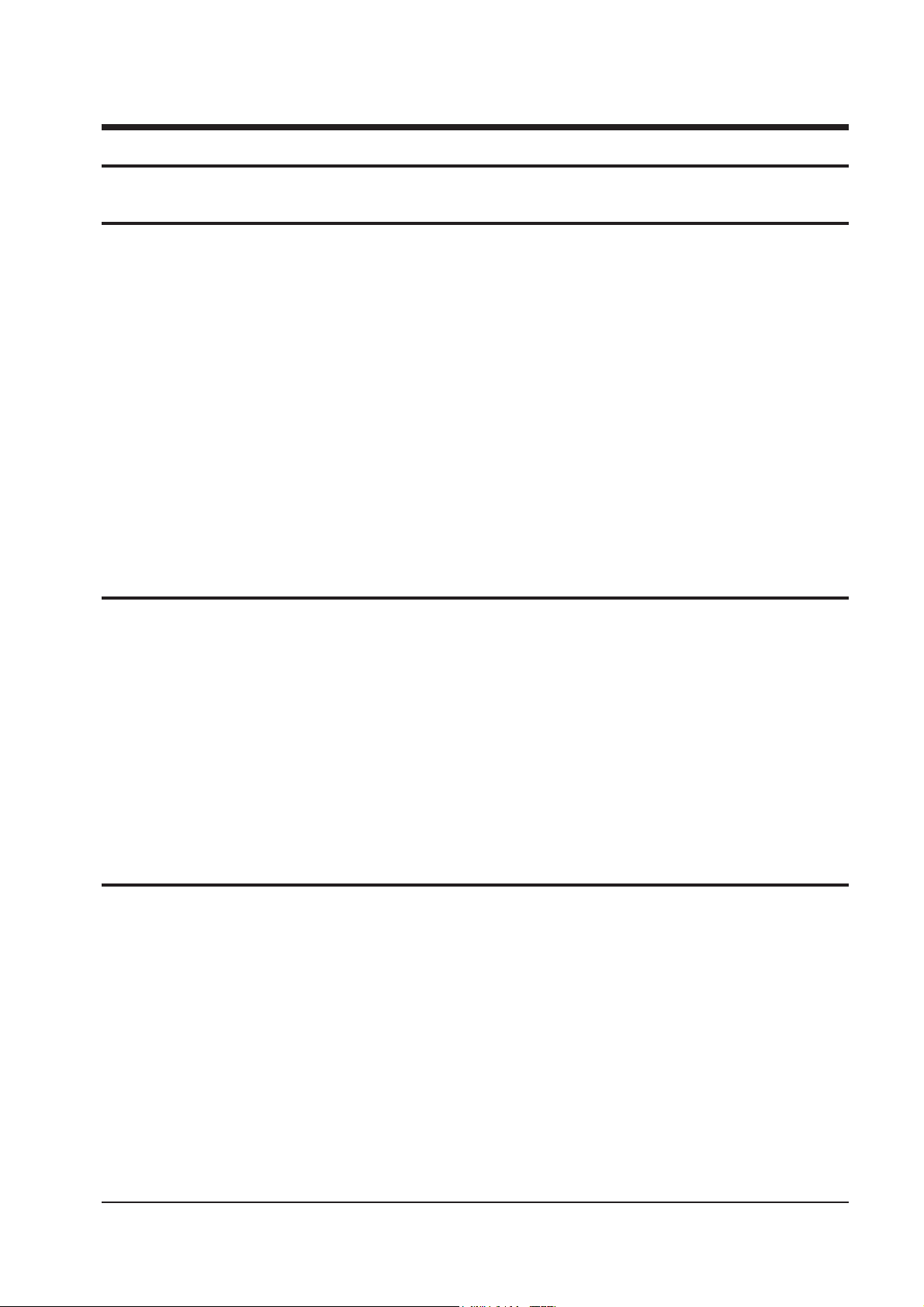
3. Plug the convergence yoke into the CRT and set it as shown in Fig. 5-1.
4. Input a black and white signal.
5. Fully demagnetize the receiver by using an external degaussing coil.
6. Turn the CONTRAST and BRIGHTNESS controls to maximum.
7. Loosen the clamp screw holding the yoke.
Slide the yoke backward or forward to produce a vertical green belt. (Fig. 5-2)
8. Tighten the convergence yoke.
9. Slowly move the deflection yoke forward.
Adjust for the best overall green screen.
10. Temporarily tighten the deflection yoke.
11. Produce blue and red rasters by adjusting the -low-light controls. Check for good purity in each field.
12. Tighten the deflection yoke.
Page 3

Alignment and Adjustments
Samsung Electronics 5-3
4 Pole Magnet
6 Pole Magnet
2 Pole Magnet
Clamper
Screw
2 POLE
PURITY
YOKE
CLAMP
SCREW
6 POLE
CONVERGENCE
4 POLE
CONVERGENCE
AD
(VE
31m/m
Vertical Green Belt
Fig. 5 - 1 Convergence Magnet Assembly
Fig. 5 - 2 Center Convergence Adjustment
Page 4

Alignment and Adjustments
5-4 Samsung Electronics
5-8 Center Convergence Adjustment
1. Warm up the receiver for at least 20 minutes.
2. Adjust the BRIGHTNESS and CONTRAST
controls for a well-defined picture.
3. Adjust the two tabs of the 4-pole magnets:
Change the angle between them.
Superimpose the red and the blue vertical
lines in the center area of the screen.
4. Turn both tabs at the same time, keeping the
angle constant: Superimpose the red and blue
horizontal lines in the center of the screen.
5. Adjust two tabs of 6-pole magnets:
Superimpose the red and blue lines with the
green. Adjusting the angle affects the vertical
lines, and rotating both magnets affects the
horizontal lines.
6. Repeat adjustments 2~4, if necessary.
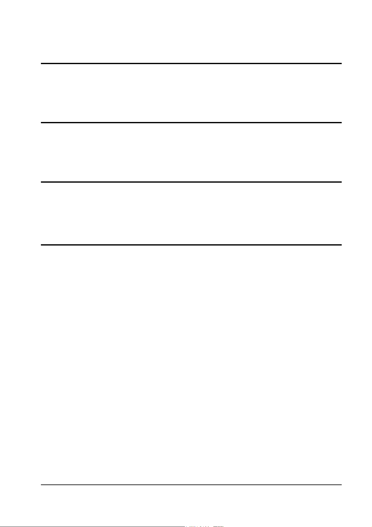
7. Since the 4-pole and 6-pole magnets interact,
the dot movement is complex (Fig. 5-3).
RED
BLUE
BLUE
RED
4-Pole Magnet Movement
GREEN
RED/BLUE
RED/BLUE
GREEN
6-Pole Magnet Movement
Fig 5-3 Center Convergence Adjustment
Page 5

Alignment and Adjustments
Samsung Electronics 5-5
5-9 Service Mode
1. Enter th Factory Mode. Press the remote-control keys in this sequence:
Video Adjustment p1
00 Red Drive 031
01 Blue Drive 031
02 Green Drive 031
03 Red Cutoff 031
04 Blue Cutoff 031
05 Green Cutoff 031
06 Sub Brightness 005
07 Sub Contrast 013
08 Sub Color 000
09 Peak Drive Limit 063
10 P. YC Delay 010
11 Sub Tint 032
12 Gamma Correction 000
Deflection p1
00 P. V - Size +031
01 P.VO - Shift +1
02 P.V - Lin +8
03 P.S - Correction 0
04 Tilt +19
05 P. EW - Width +17
06 P. EW - Parabola -46
07 P. H - Shift -85
08 P. EW - Trapizium +40
09 P. EW - UpperCorner -2
10 P. EW - LowerCorner -2
11 P. Hor - EHT -90
12 P. Ver - EHT -90
13 P. Bow -10
Option p1
00 EPG On
01 AV_LINK On
02 PAL Plus Off
03 12.8 : 9 (Q) On
04 16 : 9 Wide Off
05 Dolby Prologic On
06 3D Sound Off
07 S - Audio Mute On
08 Blue Screen On
09 UHF Only Off
10 VGA Off
11 ATM ONE RUN On
Service Mode p1
Video Adjustment
Deflection
Option
Reset
PICTURE OFF
(RED KEY)
DISPLAY P.STD MUTE
PICTURE OFF
(RED KEY)
2. Use the channel and volume keys (up/down)to move the cursor. Select an alignment parameter.
Use the volume keys(up/down)to adjust the value. Adjustment must be done separately for PAL,
SECAM, NTSC color systems. (As soon as the TV receives a signal, it switches to the correct broadcast
standard.) After adjustments are completed, press the picture off key to exit the Service Mode.
Press digit keys directly to change channel number.
▼
▼
▼
▼
▼
▼
▼
Page 6

5-6 Samsung Electronics
MEMO
 Loading...