

Page 1
Samsung Electronics 4-1
4. Alignment and Adjustments
4-1 Adjustments
Usually, a color TV needs only slight touch-up adjustment upon installation. Check the basic
characteristics such as vertical size, horizontal size, and focus. Observe the picture and check for
good black and white details. There must be no objectionable color shading: If color shading is
present, demagnetize the receiver. If color shading persists, re-do purity and convergence adjustments.
Note :
1. This ‘4. Alignment and Adjustments’ applies to KS4A chassis applications.
2. AC Power Supply: 100~230 V
3. This service manual has been written on the basis of domestic remote-control model adopting KS4A
chassis. Depending on sales location and product specifications, some of specifications herein may
be changed.
KS4A contains a dynamic focus circuit. When CRT PCB, FBT or CRT is replaced, be sure to adjust
in the following sequence:
4-1-1 General Alignment Instructions
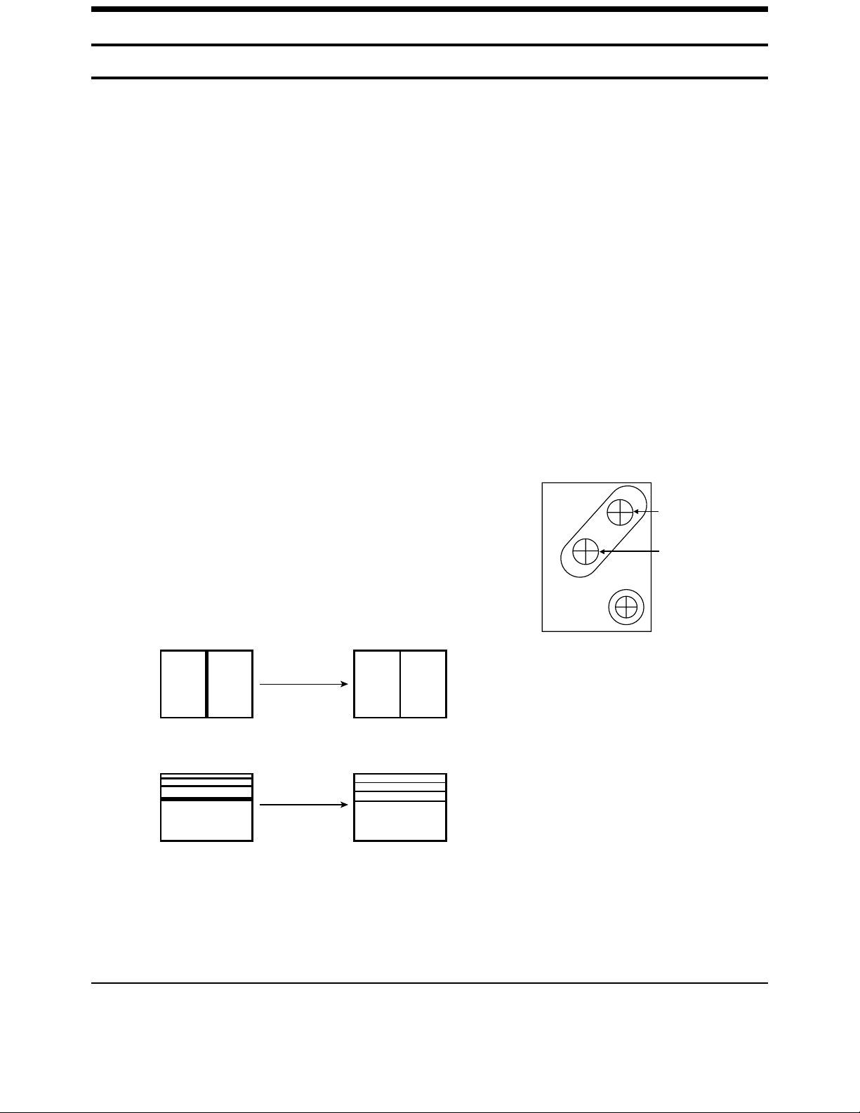
4-1-2 Focus Adjustment
Dynamic Focus Adjustment
1. Input a crosshatch pattern.
2. Select “Standard” from the menu,
3. Turn the Static Focus VR clockwise to set it to its maximum.
4. Turn the Dynamic Focus VR counterclockwise to set it to its
maximum.
5. Turn the Static Focus VR counterclockwise slowly for the clearest
center vertical line.
<FBT FOCUS PACK>
6. Turn the Dynamic Focus VR clockwise slowly for the clearest third line.
7. Check for the FOCUS of entire screen. If necessary, re-do adjustments 3~6.
STATIC FOCUS VR
NO USE
After Adjustment
1
2
3
H
DYNAMIC FOCUS VR
V
Page 2

4-2 Samsung Electronics
4-1-3 Screen Voltage Adjustment
1. Use a DC multi-meter to identify RK, GK, BK. And then adjust FBT Screen VR so that the highest
voltage becomes 175 Vp-p.
4-1-4 White Balance Adjustment
1. Select “Standard” from the menu.
2. Input an 100% White pattern.
3. In standby, press the remote-control keys in the following sequence:
Display Menu,Mute, Power on the TV set.
4. Warm up the TV set at least for 30 minutes.
5. Input a stair signal.
6. Use the Volume +/- buttons on the remote-control to select R Drive,G Drive,B Drive,Sub Cont.
7. Adjust Low-Light while viewing the darker side of screen.
8. Use the Volume +/- buttons on the remote-control to select Rcutoff,Gcutoff,Bcutoff,Sub Brt.
9. Adjust High-Light while viewing the brighter side of screen.
10. If not proper, re-adjust White Balance.
11. Press the Memory button to exit.
4-1-5 Sub-Brightness Adjustment
1. In standby, press the remote-control keys in the following sequence:
Display Menu Mute Power on the TV set.
2. Use the Channel Up/Down buttons to receive the sub bright adjustment signal.
3. Use the Volume +/- buttons to select SBT.
4. Press the Menu or Mute button on the remote control to adjust so that the seventh step on
the right of screen cannot be seen.
5. Press the Memory button to exit.
Page 3

Samsung Electronics 4-3
4-2 MICOM PINNING
4-2-1 MICOM PINNING (SDA30C264)
RXD
IR
P3.4
P3.3
P3.2
64 63 62 61 60 59 58 57 56 55 54 53 52 51 50 49
NC
NC
P3.1
P3.0
P1.6
P1.5
P1.4
P1.3
P1.2
P1.1
P1.0
VSS
VDD
XTAL2
XTAL1
RST
ALE
A16
17 18 19 20 21 22 23 24 25 26 27 28 29 30 31 32
A14
A15
VGA-ID
BS-POWER
TO;T
LED1
LED2
POWER
D-COIL
TXD
GNDD
VDDD
XTAL2
XTAL1
RESET
A16
M3L ENABLE
M3L DATA
M3L CLK
P3.6
P3.5
VDDA
VDDA
P3.7
A3
A3
VSSA
NC
P2.0
VSSA
SDA30C264
A5
A6
A8
A7
A13
A12
,AOM AFT
KEYS2
P2.2
P2.1
A10
A4
A11
FACORY
KEYS1
P0.7
P2.3
D6
D7
S | RESET
S | MUTE
P0.5
P0.6
48
47
46
45
44
43
42
41
40
39
38
37
36
35
34
33
D5
D0
P0.4 WP
P0.3 SCL2
P0.2 SDA2
P0.1 SDA1
P0.0 SCL1
P4.1 A18
P4.0 A17
VDD VDDD
VSS VSSD
A2 A2
A1 A1
A0 A0
D3 D3
D2 D2
D4 D4
D1 D1
D5
D0
D6
D7
A10
A4
A11
A5
A6
A8
A7
A13
A12
A14
A15
Page 4
4-4 Samsung Electronics
4-2-1 MICOM FACTORY MODE OPTION BYTE
Ite
m
0
1
2
3
4
5
6
7
8
9
10
11
12
13
14
15
16
OSD
CRT
Language
Group
Lgnguage
ATM
Scart/Rca
VGA
Plug&Play
Dolby prg
Pinp
Cw/Cs
Lna
Child Lock
HP jack ident
Top ttx
High
Deviation
TTX group
Carrier
mute
CIS
4:3
Europe
Russia
ON
Scart
ON
ON
ON
CS
ON
ON
ON
ON
OFF
ON
Russia
OFF
Asia/Mid
dleEast
4:3
Asia
By
Destination
OFF
Rca
ON
ON
ON
ON
CS
ON
ON
ON
OFF
ON
By
Destination
OFF
Remark
-CPT Option(Wide/4:3):P.Size format, WSS Related Option
-User Optional Language Group Setting(Europe/Asia)
-Refer to “Language Group Table”
-Select the language of destination from Language Group
* Note: Countermeasute to prevent IRAN from smuggling Once
Arabic(Persian)has been selected,the user can’t select Persian(Arabic)
-ON: ATM, OFF: Auto search
-SCART: AV-Link,AV Setup Menu, Scart jack switching
-RCA: RCA Jack switching, DVD
-Presence of VGA(ON/OFF)
Application of Dolby Prologic(ON/OFF)
-Application of Plug & Play (ON/OFF)
-Application of Pinp(ON/OFF)
-CW/CS Tuner switching option
-Application of LNA(Pinp model) (ON/OFF)
-Application of Child Lock (ON/OFF)
-ON:The main sound is cut off after identigying the headphome jack
-OFF:The headphome jack ident PIN of MICOM is used as an IIC STOP
PIN. The main sound is not cut off
-Set only the countries requesting TOP patent so that TOPTTX can be
available(Countries using TOP:Germany,Austria,Italy,Swiss)
-Solve the Sound Stop problem by tutning High Deviation On for the
countries with SOUND over modulation
-Grouping the TTX Language by Region:Refer to a separate TABLE
-For Italy Only (Option)
Page 5
Samsung Electronics 4-5
4-2-2 MICOM MODULE PIN ALIGNMENT
PIN NO
1
2
3
4
5
6
7
8
9
10
11
12
13
14
15
16
17
18
PAL MODULE
29MHz
GND
AV-LINK
5VB
MAIN AFT
CVBS
TILT
OSD/TTX-F/B
OSD/TTX-R
OSD/TTX-G
OSD/TTX-B
GND
VS2
HS2
GND
SDA2
PIN NO
19
20
21
22
23
24
25
26
27
28
29
30
31
32
33
34
35
PAL MODULE
SCL2
IIC STOP
SDA1
SCL1
WP
S-MUTE
S-RESET
VGA-ID
STD 5V
GND
KEYS1
KEYS2
IR
LED1
LED2
D-COIL
POWER
Page 6
4-6 Samsung Electronics
4-2-3 MICOM PORT ASSIGNMENT
NO
1
2
3
4
5
6
7
8
9
10
11
12
13
14
15
16
17
18
19
20
21
22
23
24
25
26
FUNCTION
P3.1
P3.0
P1.6
P1.5(PWM)
P1.4
P1.3
P1.2
P1.1
P1.0
VSS
VDD
XTAL2
XTAL1
RST
ALE
A16
A15
A14
A12
A13
A7
A8
A6
A9
A5
A11
ASSIGN
VGA-ID
NC
TILT
LED1
LED2
POWER
D-COIL
TXD
GNDD
VDDD
XTAL2
XTAL1
RESET
NC
A16
A15
A14
A12
A13
A7
A8
A6
A9
A5
A11
IN/OUT
IN
OUT
OUT
OUT
OUT
OUT
OUT
OUT
-
IN
OUT
IN
IN
IN/OUT
IN/OUT
IN/OUT
IN/OUT
IN/OUT
IN/OUT
IN/OUT
IN/OUT
IN/OUT
IN/OUT
IN/OUT
ACTIVE H/L
LOW
LOW
-
PWM
-
LOW
LOW
GND
STD 5V
-
LOW
-
-
-
-
-
-
-
-
-
-
-
EXPLANATION
VGA SIGNAL IDENT
-
TILT CONTROL
ON/OFF LED CONTROL
TIMER LED CONRTOL
PICTURE ON PORT
D-COIL CONTROL
AV LINK CONTROL
DIGITAL GND
DIGITAL VCC
12MHz XTAL
MICOM TESET PORT
NOT USED
EPROM CONTROL ADDRESS
EPROM CONTROL ADDRESS
EPROM CONTROL ADDRESS
EPROM CONTROL DATA/ADDRESS
EPROM CONTROL DATA/ADDRESS
EPROM CONTROL DATA/ADDRESS
EPROM CONTROL DATA/ADDRESS
EPROM CONTROL DATA/ADDRESS
EPROM CONTROL DATA/ADDRESS
EPROM CONTROL DATA/ADDRESS
EPROM CONTROL DATA/ADDRESS
EPROM CONTROL DATA/ADDRESS
Page 7

Samsung Electronics 4-7
NO
27
28
29
30
31
32
33
34
35
36
37
38
39
40
41
42
43
44
45
46
47
48
49
50
51
52
FUNCTION
A4
A10
D7
D6
D0
D5
D1
D4
D2
D3
A0
A1
A2
VSS
VDD
A17/P4.0
A18/P4.1
P0.0
P0.1
P0.2
P0.3
P0.4
P0.5
P0.6
P0.7
P2.3(A/D)
ASSIGN
A4
A10
D7
D6
D0
D5
D1
D4
D2
D3
A0
A1
A2
VSSD
VDDD
A17
A18
SCL1
SDA1
SDA2
SCL2
WP
S-MUTE
S-RESET
FACTORY
KEY1
IN/OUT
IN/OUT
IN/OUT
IN/OUT
IN/OUT
IN/OUT
IN/OUT
IN/OUT
IN/OUT
IN/OUT
IN/OUT
IN/OUT
IN/OUT
IN/OUT
-
IN
IN/OUT
IN/OUT
IN/OUT
IN/OUT
IN/OUT
IN/OUT
OUT
OUT
OUT
IN
IN
ACTIVE H/L
-
-
-
-
-
-
-
-
-
-
-
-
-
GND
STD 5V
-
-
-
-
-
HIGH
HIGH
LOW
LOW
-
EXPLANATION
EPROM CONTROL DATA/ADDRESS
“
“
“
“
“
“
“
“
“
EPROM CONTROL ADDRESS
EPROM CONTROL ADDRESS
EPROM CONTROL ADDRESS
DIGITAL GND
DIGITAL VCC
EPROM CONTROL ADDRESS
EPROM CONTROL ADDRESS
EPROM CONTROL BUS
EPROM CONTROL BUS
SLAVE IC CONTROL BUS
SLAVE IC CONTROL BUS
EEPROM WRITE PROTECTION
MAIN SOUND AMP MUTE
MSP RESET
BIS ADJ.MODE SELECTION
CH.UP ,CH.DOWN,VOL.UP,VOL.DOWN,MENU
Page 8
4-8 Samsung Electronics
NO
53
54
55
56
57
58
59
60
61
62
63
64
FUNCTION
P2.2(A/D)
P2.1(A/D)
P2.0(A/D)
VSSA
A3
VDDA
P3.7
P3.6
P3.5
P3.4
P3.3
P3.2
ASSIGN
KEY2
MAIN AFT
P2.0(A/D)
VSSA
A3
VDDA
M3L CLK
M3L DATA
M3L ENABLE
RXD
IR
IN/OUT
IN
IN
-
IN/OUT
IN
IN/OUT
IN/OUT
OUT
IN
IN
IN
ACTIVE H/L
-
GND
-
STD 5V
-
-
-
HIGH
-
EXPLANATION
MUTE, TV/VIDEO
ANALOG GND
EPROM CONTROL ADDRESS
ANALOG VCC
SDA5275 MEGATEXT IC CONTROL BUS
“
“
AV LINK
REMOTE CONTROL SIGNAL INPUT
Page 9

00 PKRD 03
01 BRCT 00
02 R Drive 200
03 B Drive 200
04 G Drive 200
05 Sub Curoff 06
06 Ibrm 180
07 R Cutoff 80
08 B Cutoff 80
09 G Cutoff 80
10 Sub Brt. 10
11 Sub Color 08
Samsung Electronics 4-9
4-3 FACTORY MODE CONTROL
1. Enter & Concel the Factory Mode
1) Usual Remote Control
Enter : PICTURE OFF -> DISPLAY KEY -> MENU KEY -> MUTE KEY
(Press each remote control key with in 3 seconds)
Cannel : POWER OFF -> ON
2) Factory Remote Control
Enter : DISPLAY KEY -> FACTORY KEY
(Press each remote control key with in 3 seconds)
Cannel : POWER OFF -> ON
Press the FACTORY key twice at intervals of at lease 1 second.
(Enter the AGING Mode once)
3) Set Value When Entering the Factory Mode
- Picture Mode & Sound Mode are set to the standard data
4) Adjustments
- CH. UP/DOWN Key : Use to select the item you want
- VOLUME UP/DOWN Key : Increases or decreases the value of data.
- MENU Key : Use to save the current set value in EEPROM and exit to the upper mode.
- Use the DIGIT Key to switch channels
- Use the TV/VIDEO Key th conver to the AV Mode
4-3-1 Factroy Mode Data Control
Service Mode
Video Adjustment
Y.C-Delay
Deflection normal
Deflection VGA
Option byte
Reset
12 Sub Tint 04
13 V Peaking 07
14 Svm Gain 32
15 Svm Delay 05
16 Svm Limit 85
17 Ttx Cont 120
18 Ttx brt 15
19 Pip Cont 00
20 Bcl Thrs 41
21 Bcl Tc 153
22 Bcl Gain 15/25
23 Bcl Mc 145
24 Ymax 123
25 TB_REL 204
26 BCL_TCUP 02
4-4 FACTORY MODE MENU
Video Adjustment
Page 10

4-10 Samsung Electronics
REMARK
DDP3310 R,1AEhex BIT(7:5)
-USER PEAKING CONRTOL REDUCTION (The bigger the
value is the larger the amount of REDUCTION)
VPC3230 FP BLOCK R,52hex (BIT(7:0)), R,53hex(BIT(5:0))
Reproduce the levels under BLACK LEVEL (When the
level=1,the levels under BLACK LEVEL are reproduced)
WHITE DRIVE CONTROL
- After all the SCREEN adjustments are complete, fix the
value of G DRIVE and adjust HIGH LIGHT WHITE
BALANCE.
DDP3310 R,1B1hex Bit <5:0> (Use 12 steps out of 63 steps
to add the value of sub cont to the contrast control of picture
control)
DDP3310 R,168hex (Internal brightness for measurement)
- Fixed Value by CRT
CUTOFF DRIVE CONRTOL
- After all the SCREEN adjustments are complete, fix the
value of G DRIVE and adjust LOW LIGHT WHITE
BALANCE.
DDP3310 R,167hex Bit<15:6>(Add the value of Sub
Brightness to Brightness Control of Picture Control)
DDP3310 R,1B2hex Bit<15:9>(Use 12 steps out of 63 steps
to add the value of sub color to the color control of picture
control)
VPC3230 FP Sub R,DChex - NTSC only
VPC3230 FP Sub R,28hex Bit<11:8>(Vertical peaking control)
DDP3310 R,1A7hex Bit<5:0>(VM gain control)
DDP3310 R,19Bhex Bit<3:0>(VM gain control)
DDP3310 R,19FBhex Bit<7:0>(VM limit value control)
Set TTX mode conrtast level
DDP3310 EXT BRIGHTNESS
SDA9489X R,11hex Bit<7:4>(PIPcontrast adjustment)
DD3310 R,160hex Bit <15:4>(ABL thresh hold setting)
- Set ABLOperation Point (Cuve Point)
Item
00
01
02
03
04
05
06
07
08
09
10
11
12
13
14
15
16
17
18
19
20
OS D
PKRD
BRCT
R DRIVE
B DRIVE
G DRIVE
Sub Cont
Lbrm
R Cutoff
B Cutoff
G Cutoff
Sub Brt.
Sub Color
Sub Tint
V Peaking
Svm Gain
Svm Delay
Svm Limit
Ttx Cont
Ttx brt
Pip Cont
Bcl Thrs
Range
0-7
0-1
0-255(X2)
0-255(X2)
0-255(X2)
0-12
0-255
0-255
0-255
0-255
0-20(X8)
0-12
0-12
0-12
0-63
0-15
0-255
0-255
-128-127
0-15
0-255(X8)
29A7
3
0
200
200
200
6
180
80
80
80
6
8
4
7
32
5
85
120
15
0
41
Page 11

Samsung Electronics 4-11
Item
21
22
23
24
25
26
Range
0-255(X2)
0-255(X2)
0-255(X2)
0-255(X2)
0-255(X2)
0-255
29A7
153
15/25
145
123
204
02
REMARK
DDP3310 R,161hex Bit<8:0>(ABL reduction time constamt setting)
DDP3310 R,162hex Bit<14:6>(ABL curve setting)
-Set the tilt between ABL Operation Point (Curve
Point)and MAX BEAM
DDP3310 R,163hex Bit<14:6>(Minimum RGB gain limiter)
Peak white drive limit
Peak white drive limit tilt point
ABL Cancel Conrtast Increase Time
OSD
Bcl Tc
Bcl Gain
Bcl Mc
Ymax
TB_REL
BCL_TCUP
00 Pal-B/G 00
01 Pal-D/K/L -3
02 Pal-I -3
03 Secam-B/G 03
04 Secam-D/K,L 02
05 Ntsc -1
06 Pal-av 01
07 Secam-av 03
08 Ntsc-av 01
Y.C-Delay
Item
00
01
02
03
04
05
06
07
08
Range
-3~3
29A7
00
-3
-3
03
02
-1
01
03
01
REMARK
VPC3230 FP Sub R, 23hex Bit<11:6> control(FIX)
-Set EEPROM MAP by system separately
-Video: Identified at VPC3230
-Sound: Identified at MSP3410
VPC3230 FP Sub R, 23hex Bit<11:6> control(FIX)
-Set EEPROM MAP by system separately
-Video: Identified at VPC3230
-Sound: Not Identified
OSD
Pal-B/G
Pal-D/K/L
Pal-I
Secam-B/G
Secam-D/K,L
Ntsc
Pal-av
Secam-av
Ntsc-av
Page 12

4-12 Samsung Electronics
Deflection Normal
00
01
02
03
04
05
06
07
08
09
10
11
12
13
14
15
16
17
18
19
20
21
22
23
24
25
P.
P.
P.
P.
P.
P.
P.
P.
P.
P.
P.
P.
P.
P.
P.
P.
P.
P.
P.
P.
P.
P
P
P
P
(N)
(N)
(N)
(N)
(N)
(N)
(N)
(N)
(N)
(N)
(N)
(N)
(N)
(N)
(N)
(N)
(N)
(N)
(N)
(N)
(N)
(N)
(N)
(N)
V-SIZE
V-SFT
V-LIN
S-CORR
EW-WTH
EW-PBI
H-SFT
EW-TPZ
BOW
ANGLE
EW-UPCR
EW-LOCR
EHT TIME
HOR-EHT
VER-EHT
EHTVTRS
EHTV2
EHTH2
CRNU6
CRNL6
POFS2
HSYNC DLY
PHP
PVP
PHS
PVS
20
06
00
45
-71
43/25
24
00
00
00
-12
00
07
-24
-48/90
56
44
95
00
05
-103
93
28
32
00
00
Item
00
01
02
03
04
05
06
07
08
09
10
11
12
13
14
OSD
P.(N)V-Size
P.(N)V-Sft
P.(N)V-Lin
P.(N)S-Corr
P.(N)EW-Wth
P.(N)EW-Pbl
P.(N)H-Sft
P.(N)EW-Tpz
P.(N)Bow
P.(N)Angle
P.(N)EW-UpCr
P.(N)EW-LoCr
EHT Time
P.(N)Hor-EHT
P.(N)Ver-EHT
Range
-128~127(X4)
-128~127
-128~127(X4)
-128~127(X4)
-128~127
-128~127
-128~127
-128~127
-128~127
-128~127
-128~127
-128~127
0~255(X2)
-128~127(X4)
-128~127(X4)
Initial Value
20
06
00
45
-71(200)
43(-128)
24
00
00
00
-12
00
07
-24
-48
Remark
DDP3310 R,14Dhex:VERTICAL SIZE ADJUSTMENT
DDP3310 R,14Fhex:VERTICAL SHIFT ADJUSTMENT
DDP3310 R,150hex:VERTICAL LINEARITY ADJUSTMENT
DDP3310 R,151Dhex:VERTICAL S-CORRECTIONADJUSTMENT
DDP3310 R,157hex:HORI.SIZE ADJUSTMENT
DDP3310 R,159hex:HORI.PRABOLAADJUSTMENT
DDP3310 R,144hex:HORI. SHIFT ADJUSTMENT
DDP3310 R,158hex:TRAPEZOID DISTORTION F ACTOR
ADJUSTMENT
DDP3310 R,14Bhex:BOW ADJUSTMENT
DDP3310 R,14Ahex:PARALLELGRAM DISTORTION FACTOR
ADJUSTMENT
DDP3310 R,15Ahex:UP CONER 1/3 ADJUSTMENT
DDP3310 R,15Bhex:LOW CONER 1/3 ADJUSTMENT
DDP3310 R,15Dhex EHT OPERATION TIME CONSTANT(FIX)
EHT OPERATION AT OVER DDP3310 R,147hex EHTVTRS(FIX)
EHT OPERATION AT OVER DDP3310 R,15Chex EHTVTRS(FIX)
Page 13

Samsung Electronics 4-13
Item
15
16
17
18
19
20
21
22
23
24
25
OSD
P.(N)EHIVTRS
P.(N)EHTV2
P.(N)EHTH2
P.(N)CRNL6
P.(N)CRNL6
P.(N)POFS2
P.(N)HSYNC
DLY
P(N)PHP
P(N)PVP
P(N)PHS
P(N)PVS
Range
-128~127(X8)
-128~127(X4)
-128~127(X4)
-128~127
-128~127
-128~127
0~255
0~255
0~255
0~15
0~15
Initial Value
56
44
95
00
05
-103
93
28
32
00
00
Remark
USE THE STEEP CURVE POINT OF HIGH VOLTAGE
TO SELECT BOTH EHT AND EHT2 OPERATIONS(FIX)
EHT OPERATION A T LOW BEAM
(less than EHTVTRS)
UP CONER 1/6 ADJUSTEMENT(FIX)
LOW CONER 1/6 ADJUSTEMENT(FIX)
DDP3310 EXT .RGB(PIP,VGA,TTX/OSD)CLAMPING
ADJUSTMENT(FIX)
SDP01 HORI. SYNC DELAYADJUSTMENT
-EXT .RGB(PIP ,VGA,TTX/OSD)CLAMPING ADJUSTMENT(FIX)
PIP POSITION ADJUSTMENT
PICTURE POSITION INSIDE PIP ADJUSTMENT(FIX)
Deflection VGA
00
01
02
03
04
05
06
07
08
09
10
11
12
13
14
15
16
17
18
19
20
21
22
23
V-SIZE
V-SFT
V-LIN
S-CORR
EW-WTH
EW-PBI
H-SFT
EW-TPZ
BOW
ANGLE
EW-UPCR
EW-LOCR
EHT TIME
HOR-EHT
VER-EHT
EHTVTRS
EHTV2
EHTH2
CRNU6
CRNL6
POFS2
HSYNC DLY
PHP
PVP
20
06
00
45
-71
43
24
00
00
00
-12
00
07
-24
-48
255
00
00
05
04
24
93
32
32
Page 14

4-14 Samsung Electronics
Item
00
01
02
03
04
05
06
07
08
09
10
11
12
13
14
15
16
17
18
19
20
21
22
23
OSD
V-SIZE
V-SFT
V-LIN
S-CORR
EW-WTH
EW-PBI
H-SFT
EW-TPZ
BOW
ANGLE
EW-UPCR
EW-LOCR
EHT TIME
HOR-EHT
VER-EHT
EHTVTRS
EHTV2
EHTH2
CRNU6
CRNL6
POFS2
HSYNCDLY
PHP
PVP
Range
-128~127(4X)
-128~127
-128~127(4X)
-128~127(4X)
-128~127
-128~127
-128~127
-128~127
-128~127
-128~127
-128~127
-128~127
0~255(X2)
-128~127(4X)
-128~127(4X)
-128~127(8X)
-128~127(4X)
-128~127(4X)
-128~127
-128~127
-128~127
0~255
0~255
0~255
Initial Value
20
06
00
00
-71(200)
43(-128)
24
00
00
00
-12
00
07
-24
-48
255
00
00
05
04
24
93
32
32
Remark
DDP3310 R,14Dhex
DDP3310 R,14Fhex
DDP3310 R,150hex
DDP3310 R,151hex
DDP3310 R,157hex
DDP3310 R,159hex
DDP3310 R,144hex
DDP3310 R,158hex
DDP3310 R,14Bhex
DDP3310 R,14Ahex
DDP3310 R,15Ahex
DDP3310 R,15Bhex
DDP3310 R,15Dhex
DDP3310 R,147hex
DDP3310 R,15Chex
Page 15

Samsung Electronics 4-15
4-5 3 Speed, Aging mode & Reset mode
1. 3-Speed
1) Speed up Analog Conrtol three times and Time Speed sixty times to let line productivity be
improved Analog Control.
2) Enter
- Display + 3Speed Key
3) Cancel
- The 3-Speed mode is cancelled in Master Power Off
- Press the 3Speed Key
4) OSD : The message “3-SPEED” appears on the center of screen
5) No Signal : No AUTO OFF
2. Aging Mode
1) Enter : DISPLAY KEY -> FACTORY KEY (FACTORY MODE)
-> FACTORY KEY (AGING MODE)
- When the AGING mode is entered, the OSD’s are displayed at 100% SIZE WHITE.
- Mute SOUND
2) Cancel
- FACTORY remote conrtol -> Press the FACTORY Key
- LOCAL KEY -> Use the Key MATRIX (Panel Key)
- The AGING mode remains even in MASTER S/W OFF -> ON
Cancel the AGING mode only in the above two cases.
3. Factory Reset
1) Run “Reset” on the Factory Menu.
2) Initialize the other user control data except the items that are adjusted in the Factory Mode.
3) Power Off in standby mode.
1. Bus Stop Mode (Use a Micom Stop Pin)
1) Enter the Bus Stop Mode within 200ms when 12c Stop Port is acknowledaged “LOW”.
2) Settings when entering.
- Set the screen mode “STANDARD”.
- Set Bus Line Free.
- Cancal the Bus Stop Mode when 12c Stop Port is acknowledged “High”.
3) Setting when cancelling
- Re-load data from EEPROM and then re-set the appropriate IC.
2. Remot Control Adjustment Mode (Factory Auto Adjustment)
1) Enter the Remote Control Adjustment Mode when the remote control auto adjustment code is input.
2) Settings when entering.
- Set the screen mode “STANDARD”
- Set Bus Line Free.
3) Cancel the Remote Control Adjustment Mode when the usual key code is input.
4) When the code is input, write data in both E2PRM and the appropriate IC within 20ms.
Interval between Code Inputs : 30ms
4-5-1 3-Speed
4-5-2 Bus Stop Mode & Remote Control Adjustment
Page 16

4-16 Samsung Electronics
4-6 INITIALIZATION DATA DURING RESET
Item
Volume
Balance
Main,Pip Channel
Picture Standard
Sound Standard
Add/erase
Channel Sort
LNA
Color System
PIP Position
Fine Tune
Language
Pip,Main Source
Digital N/R
TILT
P-Size
PIP-Size
TTX Contrast
Child lock
Plug & Play
Surround Mode
Pro Logic
Intialization Data
10step
Center
Custom
(Set Value:Standard)
Nautral
All Channel erased
Erased
All Channel Off
Auto
Right under
Erased
Option byte Selection
RF
Off
Center
Wide:auto,4:3:Normal
Big
Factory value
All Channel off
Option byte Selection
Off
Normal
Item
TV Power
Blue Screen
TINT
Still Picture
AV Setup
Time
On/Off Time
H/P Volume
H/P Bal.,Tbl,Bass
Programe naming
Audio out
Int.mute
Center,Rear Volume
Zoom Lift
PC Screen Shift
Country
Initialization Data
Stand by
On
Center
Cancel
Ext2,Ext3:RF
- - : - -
- - : - 10 Step
Center
All Channel Erased(*)
Volume out
Off
Center
Center
Center
Austria
Page 17

Samsung Electronics 4-17
4-7 CHASSIS FUNTION
P
I
C
T
U
R
E
PIP
FUNTION
LINE FLICKERLESS
LARGE AREA FLICKERLESS
MOTION DETECTOR
MAIN STILL PICTURE
ZOOM FUNCTION
(4:3,WIDE CRT OPTION)
ZOOM LIFT
DIGITAL N/R
COMB FILTER
CTI
SCAN MODE
P-STD
COLOR TONE
DYNAMIC-FOCUS
VM
TILT CONTROL
VGA
DVD
MULTI PIP
LNA ON/OFF
SWAP,ROTATE,SIZE,SCAN
PAL
YES
YES
YES
YES
NORMAL -> 16:9 -> ZOOM
AUTO WIDE->P ANORAMA->4:3->16:9->ZOOM1->ZOOM2
YES
YES
4H
DIGIT ALCTI
NA TURALSCAN -> DIGIT ALSCAN -> PORGRESSIVE SCAN
CUSTOM->ST ANDARD->SPORTS->MILD->NATURAL
NORMAL -> WARM1- > WARM2 -> COOL1 -> COOL2
YES
YES
YES
YES
RCAJACK MODEL ONL Y-> YUV MODE
YES
YES
YES
Page 18

4-18 Samsung Electronics
FUNTION
ATM
PLUG & PLAY
AV LINK
TTX
OSD TYPE
SLEEP TIMER
ON/OFF TIMER
CHILD LOCK
PROGRAMMABLE CH.
TUNING SYSTEM
SORT & NAME
INFORMATION
ADD/ERASE
DOLBY PROLOGIC
A2 STEREO
EQUALIZER
NICAM STEREO
OUTPUT (MPO)
S-STD
HEADPHONE VOLUME CONTROL
FRONT
REAR
PAL
ATM(EU)
YES
SCART JACK MODEL ONLY(SCART1)
MEGATEXT
OSG
YES
YES
YES
100 CH. MENORY
PROGRAMMABLE F/S
YES
YES(NAME,SOUND MODE,CHILD LOCK)
YES(CHANNEL SKIP)
YES
YES
YES
YES
MAIN:12+12W, SUR:12+12W, CENTER:12W
CUSTOM->ST ANDARD->MUSIC->MOVIE->SPEECH
YES
1 S-VHS,1RCAINPUT ,1HEADPHONE,1 VGA
SCART JACK MODEL: 1RF,3SCAR T,DOLBY JACK
RCAJACK MODEL:1RF ,1 S-VHS,3RCAIN, 1DVD IN,
1 MONITOR OUT, DOLBY JACK
P
U
N
T
I
O
N
EXT
JACK
S
O
U
N
D
Page 19

Samsung Electronics 4-19
4-8 PCF9591 PORT ASSIGNMENT (JACK IDENT)
PIN
NO
1
2
3
4
5
6
7
8
9
10
11
12
13
14
15
16
FUN
AINO
AIN1
AIN2
AIN3
A0
A1
A2
VSS
SDA
SCL
OSC
EXT
AGND
VREF
AOUT
VDD
ASSIGN
SC1-ID(AV1/DVD-ID)
SC2-ID(AV2/DVD-ID)
SC3-ID(AV3)
FAV-ID/FS-ID
GND
GND
GND
GND
SDA2
SCL2
OSC
GND
AGND
VREF
D/A OUT
VDD
SCART JACK OPTION IDENT
VOLTAGE(V)
RCAJACK MODEL IDENT VOLTAGE(V)
0~1.5
NOT CON.
NOT CON.
NOT CON.
1.6~3.4
WIDE MODE
WIDE MODE
WIDE MODE
3.5~5.0
4:3 MODE
4:3 MODE
4:3 MODE
0~2.2
NOT CON.
2.3~2.7
DVD
2.8~4.0
AV1
NOT CON.
NOT CON.
4.1~5.0
ALL CON
AV2
F-VIDEO
AV2 SVHS
NOT CONNECTION
FRONT-SVHS
AV3
IC ADDRESS SLECTION
DIGITALGND
IIC CONTROL BUS
-
EXT/INT OSC CONTROL
ANALOG GND
-
NOT USED
5V
Page 20

4-20 Samsung Electronics
4-9 LOCAL KEY ASSIGNMENT
1. Local(Pannel) Key List
- LOCAL MENU : Main Menu Control
- CH + : Channel Up & Menu Control
- CH - : Channel Down & Menu Control
- VOLUME + : Volume Up & Menu Control
- VOLUME - : Volume Down & Menu Control
- TV/VIDEO : TV/VIDEO MODE CHANGE
2. Local Key (8 Bit ADC)
KEY1
KEY2
KEY NAME
VOLTAGE
KEY NAME
VOLTAGE
KEY NAME
VOLTAGE
KEY NAME
VOLTAGE
CH. DOWN
0V~0.62V
0V~0.62V
CH. UP
0.93V~1.55V
LOCAL MENU
0.93V~1.55
VOL.DOWN
1.86V~2.5V
TV VIDEO
1.86V~2.5V
NOT OPER
3.74V~5.00V
NOT OPER
3.74V~5.00V
Page 21

Samsung Electronics 4-21
* Language Group
NO
1
2
3
4
5
6
7
8
9
10
11
12
13
14
15
16
17
18
Europe
English
Bulgalian
Croatioan
Czech
Dutch
French
German
Greek
Hungarian
Italian
Polish
Portuguese
Rumanian
Russian
Spanish
Swedish
Turkish
Yogo
Asia
English
Arabic
French
Indonesian
Malay
Persian
Urud(Pakistani)
Remark
Page 22

4-22 Samsung Electronics
* TTX Language Groutp
NO
0
1
2
3
4
5
6
7
C14
0
0
0
0
1
1
1
1
C13
0
0
1
1
0
0
1
1
C13
0
1
0
1
0
1
0
1
W-Europe
English
French
Swedish/
Finnish/
Danish
Turkish
German/
Dutch/
Flemish
Spanish/
Portuguese
Italian
Greek
E-Europe
Polish
Russian
Hungarian
Czech/
Slovak
German/
Dutch/
Flemish
Slovenian/
Serbo
Lithuanian
Rumanian
Russian
Polish
Russian
Estonian
Czech/
Slovak
German/
Dutch/
Flemish
Ukranian
Lettish
Rumanian
Arab
English/
Arabic
French/
Arabic
Thai
Turkish
German/
Dutch/
Flemish
Spanish/
Portuguese
Italian
Arabic
Ireland
English
French
Swedish/
Finnish/
Danish
Turkish
German/
Dutch/
Flemish
Icelandic
Italian
Greek
Hebrew
English
French
Swedish/
Finnish/
Danish
Turkish
German/
Dutch/
Flemish
Hebrew/
Arabic
Italian
Rumanian
X22 line Factory mode TTX Group
Page 23

Samsung Electronics 4-23
4-10 Screen Change (I2C Bus Geometric Adjustment)
1 V - SHIFT
6 V - SIZE
2 V - LIN
3 HEW- WITH
4 H PARABOLA (EW)
7 S-CORR
8
H TRAPIZIUM (EW)
9
H SHIFT
5 H CORNER (EW-V[CR, EW-;PCR)
Page 24

4-24 Samsung Electronics
MEMO
 Loading...