

Page 1
2
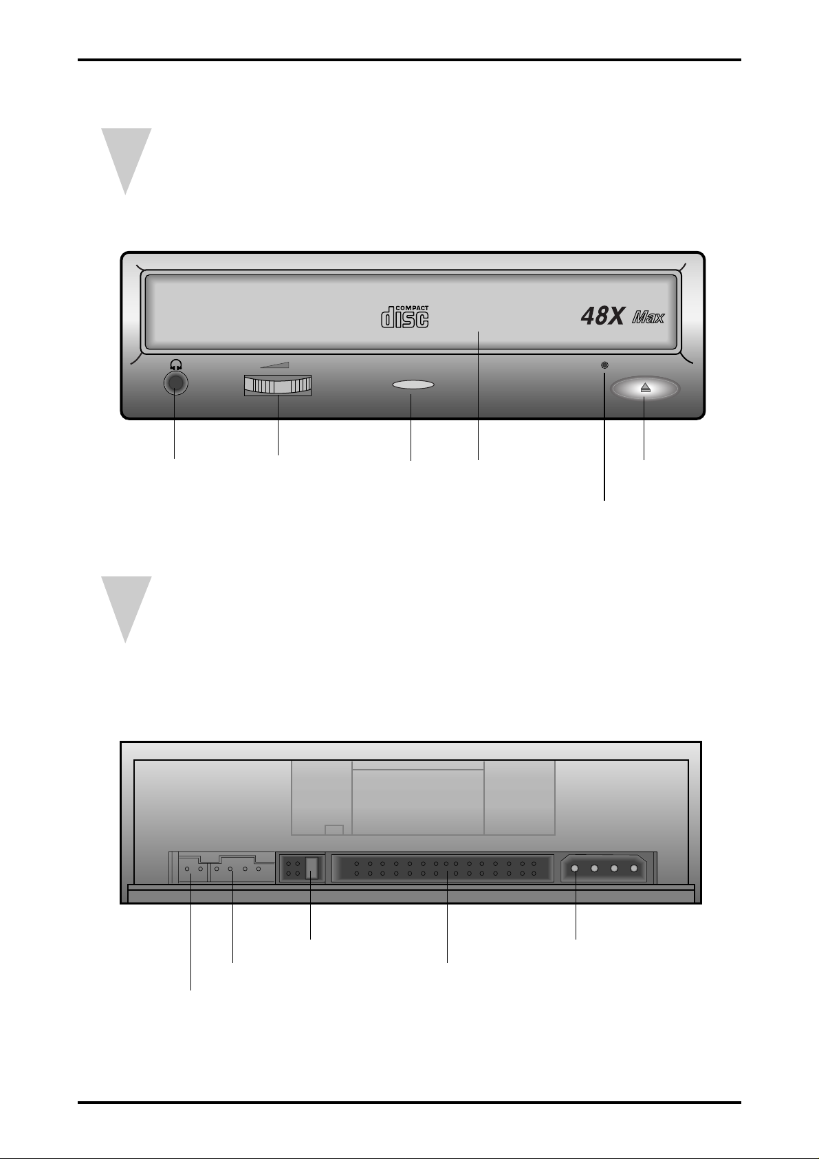
External Part Name
1.Front
2.Rear
Earphone jack
Digital output terminal
(Optional)
Sound output terminal Interface terminal
Master/Slave select pin Power terminal
Up/Down Volume
LED Stop/Open button
EmergencyHOLE
Disc tray
Page 2

3
Disassembly Method
1. COVER BOTTOM ASSY disassembly
Remove 4 screws 31 on the bottom of COVER BOTTOM ASSY, lift the back up and disassemble
31COVER BOTTOM ASSY as shown in the figure of the next page.
2. COVER-TOP disassembly
After disassembling 6 hooks of FRONT ASSY 29 from COVER TOP 30 , pull COVER TOP 30 forward
and disassemble it.
3. ASSY DECK+PCB MAIN disassembly
Disassemble FPC PICK-UP 24 and FPC MOTOR 25 connected between assy deck and PCB main, then
disassemble between deck and PCB main.
Page 3

4
Exploded V iews
Page 4

5
Device Part List
NO PARTS SPECFICATION COUNT Code
FULL DESK ASSY
ASS’Y CLAMPER BG97-00013A
1 -BRKT CLAMPER SECC 0.8T BG61-00010A
2 -CLAMPER UPPER POM BG66-90013A
3 -CLAMPER LOWER POM BG66-00001A
4 -MAGNET CLAMPER Nd-Fe-B(N35H) BG33-30001D
5 -BRKT MAGNET SECC 0.8T BG61-00018A
6 TRAY DISC PC/ABS BG66-00002A
ASS’Y LOADING BG97-00017A
7 -MAIN FRAME ABS BG61-00011A
16 -MOTOR DC SM-2412L BG31-00002A
-SCREW MACHNE M1.7*3 AC60-10027A
9 -GEAR MOTOR POM M90-44 BG66-20139A
11 -GEAR B DELLIN 100P BG66-20140A
12 -GEAR A POM(M90-44) BG66-20141A
32 -GEAR D NYLON66(ZYTEL 101L) BG66-20143A
10 -GEAR TRAY DELLIN 100P BG66-00004A
13 -RING SPRING POM(M90-44) BG60-42003A
-SPRING LEVER SUS304WPB BG61-60038A
-LEVER SWITCH POM(M90-44) BG66-30017A
14 -SLIDE CAM PBT BG66-00003A
-SCREW TAPTITE M1.7*5 AH60-10145A
33 MOTOR SPINDLE 5E7 BG31-00010A
17 ASS’Y TURN TABLE BG97-00071A
-TURN TABLE ABS AL BG66-00010A
-BRKT T/T SECC 1.0T BG61-00018A
-COVER T/T SUS 0.3T BG63-30018A
-BALL TURN TABLE NI TRONIC BG70-10316A
-RUBBER T/T CR 0.45T Ø28*21 BG73-10107A
SCREW SP MOTOR M1.7*3 BG60-10020A
ASSY FEEDING BG97-00021A
19 -CHASSIS SUB ABS+PC BG61-00001A
15 MAIN BASE(M) OUTSERT BG61-00002A
SECC 1.6T BG61-00004A
20 -RUBBER INSULATOR BUTYL BG73-00001A
-SCREW TAPPING AH60-10143A
21 -FFC SP MOTOR POLYESTER 11P BG41-00021A
22 -MOTOR STEP SPS-15RF-051K BG31-00001A
-SCREW TAPPING M1.7*5(BLK) AC60-10059A
23 -PAD DECK PORON BG69-00012A
SCREW SP MOTOR M1.7*3 AC60-10059A
24 SHAFT PU(R) SUS420J2(89) BG61-00009A
25 PICK UP KSS575B BG30-00002A
26 FFC PICK UP POLYESTER 17P BG41-00009A
27 ASS’Y SLIDER STEP BG97-00018A
SLIDER STEP POM(NW-02) BG66-00005A
HOLDER-SLIDER
SPRING-STEP
28 DOOR TRAY ABS BG64-00007A
29 PANEL FRONT ASSY BG97-00250A
-PANEL FRONT ABS
-KNOB EJECT ABS
-LENS LED ACRYL MILKY
30 COVER TOP SECC 0.6T BG63-00011A
31 ASS’Y COVER BOTTOM BG97-00251A
32 SCREW-TAPTITE M2.6 * 6 AC60-10074A
33 BRKT-MAIN BASE SECC 1.6T BG61-00029A
 Loading...