

Page 1
18
Troubleshooting
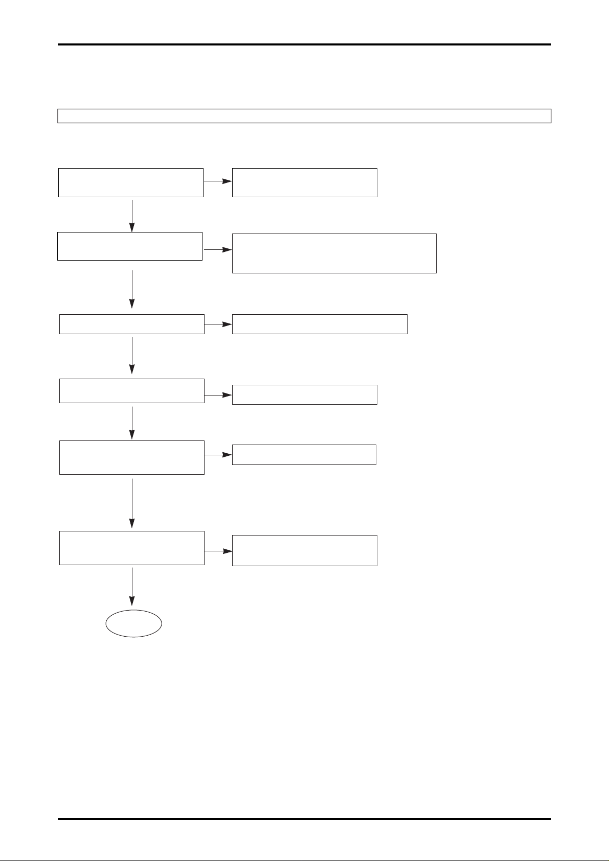
+5V, +12V of CN701 is normally inputted
after connection of power cable?
X201, X301, X401 oscillate ?
Check power short and power supply cable
connection state
①
IC201 75pin, IC301 12pin, 54pin IC401 87pin for power input
➁
Check C303, C304, C207, C208, R210, C402, C401soldering
➂
If normal replace X201, X301, X401
IC301 19pin change from 0V to 5V ?
Inputted Voltage of IC301 5pin is 1.5V~2.0V ?
Check R401, R402, R333 Rsoldering
Y
Y
N
N
N
N
N
Input / output IC301 57pi n~80pin,
1pin~4pin
pulse waveform ?
Check IC301 pin soldering
Y
Y
Y
N
In case FLASH ROM Memory of IC301 16pin
0V, and Rom memory inputted 5V ?
Check R320, R321 soldering
Check R301, R302 soldering
Equipments required at repair
1. Oscilloscope(100MHz or more ) 2. PROBE for Oscilloscope(10:1)
3. PC(486 ormore)
Verify the circuit of power unit and the first status(Plug-in the power cable without I/F cable and verify.)
A
Page 2
19
N
N
N
N
N
Disk insert
Tray in / out ? Refer to Tray open / close
Y
Y
Laser diode on ? Refer to No laser diode on
Y
Laser diode on ? Refer to No focus lock
Y
Focuse up / down ?
Y
Disc rotates ? Refer to No disc rotation
Y
Pause state
❋ Pause state : LED off as disc rotation state and continue 1 track jump
Y
Spindle lock ?
Y
Input Voltage of IC201 9pin, 21pin 3.6V ?
Pick up moves in at power on after moving
out ?
Check after SET assembly
1TRACK JUMP TE
A
Page 3
20
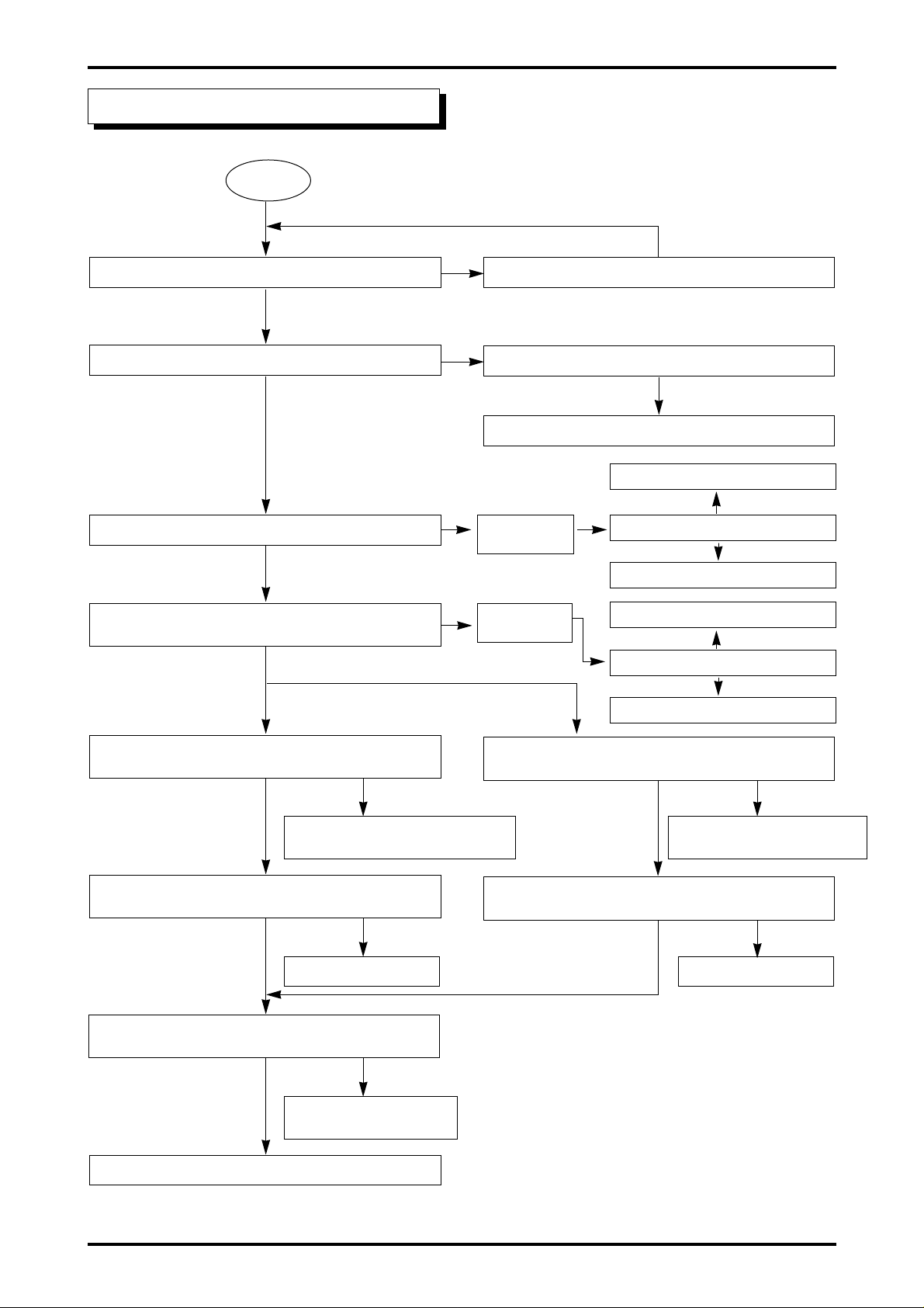
No tray open/close
FPC is normally inserted in CN702? Retest after inserting FPC in CN702 properly
Start
N
Check SW702 pattern and soldering
❋ FPC : Flexible Printed Circuit
Replace SW702
After FPC short check, no error, check SW soldering of deck
FPC of CN702 is normally inserted?
Retest after inserting FPC in CN702 normally
After FPC short check, no error, check SW soldering of deck
FPC of CN702 is normally inserted?
Retest after inserting FPC in CN702 normally
N
N
N
IC301 44pin is 0V at pressing SW702?
Y
IC301 29pin is 0V with tray in?
CN702 4pin
becomes 0V?
CN702 2pin
becomes 0V?
N
N
N
N
IC301 28pin is 0V with tray open?
Check R502,R503,R509 soldering.
CheckIC301,33pin, 34pin soldering.
Check R502,R503, soldering.
CheckIC301,33pin, 34pin soldering.
Replace IC501Replace IC501
Y
Y
Y
Y
IC501 11pin change from 1.75V to +0V at pressing SW702?
N
N N
N
N
IC301 33pin changes from 1.75V to 5V at pressing SW702?
IC501 13pin changes from +2.4V to +0.7V, and 15pin
from +2.4V to +3.9V, at pressing SW702?
IC501 14pin chages from 2.4V to 3.9V
and 15pin from 2.4V to 0.7V at pressing SW702?
Output Voltage of IC501 13Pin is impressed into
LOADING (-) and IC501 14Pin(+)?
Check pattern and soldering
between CN702 and IC501
Replace loading Motor.
Y
YY
YY
Y
OPEN tary repair
CLOSE operation repair
Page 4

21
No laser on
Refer to ‘No tray open/close’
IC101 10pin changes from 0V to +3.3V? Refer to ‘Check power source and initial state’
N
N
IC101 9pin changes from 4.2V to 3.6V?
Check IC101 power input and replace.
Y
Open and close tray(Disc insettion)
Y
CN501 3pin changes from 2V to 2.5V?
Check D101, L101, Q102, R102, C103 soldering
Y
CN501 2pin changes from 0V to 0.7V? Check Pick-up FPC connection state
N
N
N
Y
Replace pick-up
Y
Page 5

22
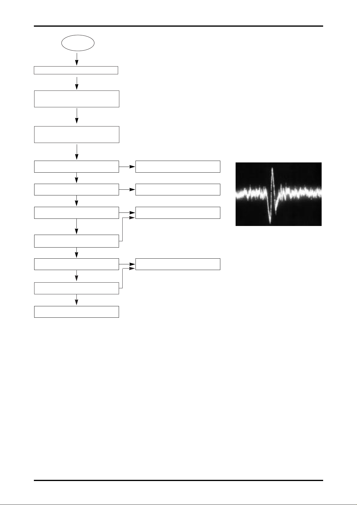
No SLED operation
Move pick-up out.
Insert 2 FPC and power cord.
SLED runs normally.
Y
Pick-up moves in?
The below waveform is outputted in
IC301 22Pin, 23pin ?
N
Refer to 'Check power source and initial state'
N
Voltage of IC501 4pin - 12V,
5pin - 5V?
Check R506, R507,
R512 soldering.
After checking IC501
soldering, no error, replace
IC
N
Y
N
N
The below signal is inputted
in CN503 A,A, B,B termial?
Y
The opposition signal is inputted
in CN503 A, A, B, B termial?
Y
Replace SLED Motor.
Y
Page 6

23
No spindle motor rotation
Focus lock? Refer to 'No focus lock'
Refer to 'No focus lock'
N
N
N
N
N
Check C519 soldering
Check IC502 23pin soldering
N
Check IC301 38pin soldering
Check R323 soldering
The below waveform is
inputted in IC502 22Pin?
IC502 4Pin, 29pin is 12V?
Insert disc.
Y
Y
Y
Y
Y
Y
Y
Y
Spindle motor kick signal
IC502 5Pin is 5V?
Replace IC502
Spindle Motor FPC is connected?
Replace spindle Motor
IC502 5Pin is 5V?
The below waveform is inputted in IC502
Y
Page 7

24
No audio output
Focus lock? Refer to 'No focus lock'
N
Insert audio disc.
Y
Y
Spindle Motor rotates? Refer to 'No Spindle Motor rotation'
N
Y
Audio signal is outputted in
IC201 77, 80Pin?
Check IC201 power and soldering.
N
Replace IC201
N
Y
Audio signal is outputted in
IC701 1. 7Pin?
Check IC701 power input and
peripheral integer VR soldering.
N
Replace IC701
N
Y
Audio signal is outputted in JK 701 Check L702, L701 soldering
N
Page 8

25
When installing is impossible
Does INSTALL message appear? Normal
N
Connect power cable and I/F cable
between PC and CD-ROM
Y
Do the digital signal of IC301 and IC401
communication pattern change from 0V to
5V?
Check the soldering of IC401, IC301
and pattern open/short
N
N
Y
Y
IC401, CN701, is normal
communication singnds?
Check the soldering of Damping
Resister and IC, I/F Wafer
N
Connet 1/F cable
Y
Is IC301 55PIN 5V when main power
turns on?
Check main power-end and initial
state
N
Does X401 oscillate?
Check soldering of C401, C402
Y
Y
Is IC201 95PIN 5V?
N
Y
 Loading...