

Page 1

Notices
No part of this publication may be reproduced, stored in a retrieval system, or
transmitted,in any form or by any means, mechanical photocopying, recording or
otherwise, without the prior written permission of the manufacturer.
The information within this manual is subject to change without notice.
The manufacturer shall not be held liable for technical or editorial errors or omissions
contained in herein; nor for incidental or consequential damages resulting from the
furnishing, performance or use of this material.
Microsoft Windows is a re gistered trademark of the Microsoft Corporation.
Product names mentioned herein are for identification purposes only , and may be
trademarks and/or registered trademarks of their respective companies.
Copyright 2001 All rights are reserved
Notices i
Page 2

Important Safety Information
Safety Instructions
Your system is designed and tested to meet the latest standards for safety of
information technology equipment. However, to ensure safe use of this product, it is
important that th e safety instructions marked on the product and in thedocumentation
are followed.
Always follow these instructions to help guard against personalinjury and
damage to your system.
i
Setting Up your System
Read and follow all instructions marked on the product and in the
•
documentation before you operate your system. Retain all safety and operating
instructions for future use.
Do not use this product near water or a heat source such as a r adiator.
•
Set up the system on a stable work surface.
•
The productshould be operated only with the type of power source indicatedon
•
the rating label.
Ensure that the electricaloutlet you are using to power your equipmentis easily
•
accessible in case of fire or short circuit.
If your computer has a voltage selector switch, make sure that the switch is in
•
the proper position for your area.
Openings in the computer case are provided for ventilation. Do not block or
•
cover these openings. Make sure you provide a dequate space, at least 6 inches
(15 cm), around the system for ventilation when you set up your work a rea.
Never insert objects of any kind into the computer ventilation openings.
ii Users Manual
Ensurethat the fan vents on the bottom of the casing are clear at all times. Do
•
not place the computeron a soft surface, doing so will block the bottom vents.
The computer product is equipped with a three-wire power cord to make sure
•
that the product is properly grounded when in use. The plug on this cord will fit
only into a grounding-type outlet. This is a safety feature. If you are unable to
insert theplug into an outlet, contact an electrician to install the appropriate
outlet.
Page 3

If you use an extension cord with this system, ma ke sure that the total ampere
•
rating on the products plugged into the extension cord does not exceed the
extension cord ampere rating.
Care During Use
Do not walk on the power cord or allow anything to rest on it.
•
Do not spill anything on the system. The best way to avoid spills is to not eat or
•
drink near your system.
Some products have a replaceable CMOS battery on t he system board. There is
•
a danger of explosion if the CMOS battery is replaced incorrectly. Replace the
battery with the same or equivalent type recommended by the manufacturer.
Dispose of batteries according to the m anufacturer’s instructions. If the CMOS
battery requires replacement insure that a qualifiedtechnician performs the task
When the computer is turned off, a small a mount of electrical current still flows
•
through the computer. To avoid electrical shock, always unplug all power
cables, remove the battery and modem cables from the wa ll outlets before
cleaning the system.
Unplug the system from the wa ll outlet and refer servicing to qualified
•
personnel if:
– The power cord or plug is damaged.
– Liquid has been spilled into the system.
– The system does not operate properly when the operating instructions are
followed.
– The system was dropped or the casing is damaged.
– The system performance changes.
Replacement Parts and Accessories
Use only replacement parts and accessories recommended by manufacturer.
To reduce the r isk of fire, use only No. 26 AWG or larger telecommunications
line cord.
Do not use this product in areas classified as hazardous. Such areas include
patient care areas of medical and dental facilities, oxygen rich environments,
or industrial areas.
Important Safety Information iii
Page 4

Battery Disposal
Do notput rechargeable batteries or products powered by non-removable
rechargeable batteries in t he garbage.
Contact the Samsung Helpline for information on how to dispose of batteries that you
cannot use or recharge any longer.
Follow all local regulations when disposing of old batteries.
iv Users Manual
Page 5

Federal Communications Commission (FCC)
This device complies with Part 15 of the FCC Rules. Operation issubject to the
following two conditions:(1) this device may not cause harmful interference, and (2)
this device must accept any interference received, including interferencethat may
cause undesired operation.
Thisequipmenthas beentestedandfound to complywiththe limitsforaClass
B digital device pursuant to Part 15 of the FCC Rules. These limits are
designed to provide reasonable protection againstharmful interference in a
residential installation. This equipment generate uses and can radiate radio
frequency energy and if not installed and used in accordance with the
instructions may cause harmful interference will not occur in a particular
installation. If this equipment does cause harmfulinterference to radio or
television reception, which can be determined by turning the equipment off
andon,theuser isencouragedto trytocorrecttheinterferencebyone ormore
of the following measures:
Reorient or relocate the receiving antenna.
•
Increase the separation between the equipment and receiver.
•
Connect the equipment into an outlet on a circuit different from that to which
•
the receiver is connected.
Consult the dealer or an experienced radio/TV technician for help.
•
If necessary, the user should consult the dealer or an experienced radio/television
technicianfora dditional suggestions. Theusermayfindthefollowing booklethelpful:
"Something About Interference." This is available at FCC local regional offices. Our
company is not responsible for any radio or television interference caused by
unauthorized modifications of this e quipment or the substitution or attachment of
connecting cables and equipment other than those specified by our company. The
correction will be the responsibility oftheuser.Useonly shieldeddatacableswith this
system.
Federal Communications Commission (FCC) v
Page 6

Federal Communications Commission Part 68 Statement
Note:
This equipment compiles with part of the FCC rules. On the back of this equipment is
a labelthatcontains, among other information,theFCCregistration numberandringer
equivalence number(REN) for this equipment. If requested, this information must be
provided to the telephone company.
This equipment uses the following USOC jacks : RJ11C
An FCC complianttelephone cord and modular plug is provided with this equipment.
This equipment is designed to be connected to the telephonenetwork or promises
wiring using a compatible modularjack which is Part 68 compliant. See Installation
Instructions for details.
The REN is used to determine the quantity of deviceswhich may be connected to
telephone line. Excessive RENs on the telephone line may result in the devices not
ringing in response to an incoming call. In most, but not all areas, the sum of RENs
should not exceed five(5.0). To be certain of t he number of devices that may be
connectedtoaline, as determinedby total RENs, contact the local telephonec ompany
to determine the maximum REN for the calling area.
If the terminal equipment causes harm to the telephone network, the Telephone
Company will notify you in advance that temporary discontinuance of service may be
required. But if advance notice is not practical, the telephone company will notify the
customerassoonas possible. Also,youwillbe advised of yourrightto file acomplaint
with the FCC if you believe it is necessary.
The telephone company may make changes in its facilities, equipment, operations, or
procedures that could a ffect the operation of the equipment.If this happens, the
telephone company will provide advanced n otice in order for you to make necessary
modifications to maintain uninterrupted service.
If trouble is experienced with this equipment (SENS Modem) for repair or warranty
information,please contact your local distributor. If the e quipment is causing harm to
the telephone network, the telephone company may request that youdisconnect the
equipment until the problem i s resolved.
The user must use the accessories and cables supplied by the manufacturer to get
optimum performance from the product.
No repairs may be done by the customer.
Thisequipmentcannot be used on publicc oin phone serviceprovided by thetelephone
company. Connection to party line service is subject to state tariffs.
vi Users Manual
Page 7

The Telephone Consumer Protection Act of 1991 makes it unlawful for any person to
useacomputerorother electronicdevice,includingfaxmachines,tosend any message
unless such message c learly contains in a m argin at the top or bottom of each
transmitted page or on the first page of the transmission, the date and time it is sent and
anidentificationofthe businessor otherentity,or otherindividualsending themessage
and the telephone number of the sending machine or such business, other entity, or
individual. (Thetelephonenumber provided may notbeanynumberfor which charges
exceed local or long-distance transmission charges.)
In order to program this information into your fax machine, refer to your
communications software user manual.
CTR21 Statement
The equipmenthas been approvedinaccordancewithCouncilDecision 98/482/ECfor
pan-European single terminal connection to the public switched telephone network
(PSTN). However, due to differences between the individual PSTNs provided in
different countries, the approval does not, of itself, give an unconditional assurance of
successful operation on every PSTN network termination point.
In the event of problems, you should contact your equipment supplier in the first
instance.
Canadian Radio Interference Regulations
This apparatus does not exceed the class B limits for radio noise emissions set out in
the radio interference regulations of the Canadian Department of Communications.
Le présent appareil n’émet pas de bruits radioélectriques dépassant les limites
applicable aux appareils de la classe B prescrites par le règlement de brouillage
radioélectrique dicté par le Ministère des Communications du Canada.
Federal Communications Commission (FCC) vii
Page 8

Laser Safety
All systems equipped with CD or DVD drives comply with the appropriate safety
standards, including IEC 825. The laser devices in these components are classified as
“Class 1 Laser Products” under a US Department of Health and Human Services
(DHHS) RadiationPe rformance Standard.Shouldthe unit ever needservicing,contact
an authorized service location.
Laser Safety Note:
Use of controlsoradjustments or performanceofprocedures other thanthose
specified in this manual may resultin hazardous radiation exposure. To
prevent exposure to laser beams, do not try to open the enclosure of a CD or
DVD drive.
viii Users Manual
Page 9

Power Cord Requirements
The power cord set (wall plug, cable and AC adapter plug) you received with your
computer meets the requirements for use in the country where you purchased your
equipment.
Power cord sets for use in other countries must meet the requirements of the country
where you use the computer. For more information on power cord set requirements,
contact your authorized dealer, reseller, or service provider.
General Requirements
The requirements listed beloware applicableto all countries:
The length of the power cord set must be at l east 6.00 feet (1.8m) and a
•
maximum of 9.75 feet (3.0m).
All power cord sets must be approved by an acceptable accredited agency
•
responsible for evaluation in the country where the power cord set will be used.
The power cord set must have a minimum current capacity of 7 A and a
•
nominal voltage rating of 125 or 250 volts A C, as required by each country’s
power system.
The appliance coupler must meet the mechanical configuration of an EN 60
•
320/IEC 320 Standard Sheet C13 connector,for mating with appliance inlet on
the computer.
Power Cord Requirements ix
Page 10

Country-Specific Power Cord Set Requirements
The requirements listed below are applicable to the specific countrylisted:
Country
Australia EANSW 1
Austria OVE 1
Belgium CEBC 1
Canada CSA 2
Denmark DEMKO 1
Finland FIMKO 1
France UTE 1
Germany VDE 1
Italy IMQ 1
Japan JIS 3
The Netherlands KEMA 1
Norway NEMKO 1
Sweden SEMKO 1
Switzerland SEV 1
United Kingdom BSI 1
UnitedStates UL 2
Accrediting
Agency
Applicable Note
Numbers
Notes:
x Users Manual
1.Flexible cord must be Type HO5VV-F, 2-conductor,1.0 mm² conductor
size. Power c ord set fittings (appliance coupler and wall plug) must bear
the certification mark of the agency responsible for evaluation in the
country where it will be used.
2.Flexible cord must be Type SVT or equivalent, No.18 AWG. Wall plug
must be a two-pole grounding type.
3.Appliance coupler, flexiblecord, and wall plug must bear a "T" mark and
registration number in accordance with the Japanese Dentori Law.
Flexible cord must be Type VCT or VCTF, 2-conductor, 0.75 mm²
conductor size. Wall plug must be a two-pole grounding type with a
Japanese Industrial Standard C8303 (15 A, 125V) configuration.
Page 11

Using Your Documentation
Congratulations on your purchase of a notebook computer with the Windows® XP
operating system. Whether you are new to using a portable computer o r are an
experienced user, this user’s manual can help you get the most from your computer.
Manual Documentation Conventions
Information Icons
Three icons and their a ssociated messages appear in this manual. The information
icons are placed before the step/information they apply to:
Warning:
Indicates the possibility of personal injury.
Caution:
Warns you of possible damage to equipment or data.
Note:
Informs you of specialcircumstances.
Keyboard Conventions
Keys that you need to press to perform certain functions are displayed in the manual
using a small graphic of the button. For example:
<Ctrl>
indicates the control key (Ctrl on the keyboard).
If you need to press two keys at the same time, the key names are shown joined by a
plus sign. For example:
<Alt+PgUp>
means that you should press the Alt key and hold it and then press thePgUp key.
Using Your Documentation 1
Page 12

CD-ROM Device Naming Convention
In many installation programs you will have to get a program from the CD-ROM
device. The program installation sequence assumes that the CD is drive d:\, however
this is not always the case. The name of the CD-ROM drive is the letter following the
letter assigned to yourlast HDD. For instance, if you have one HDD with two
partitions, the HDD is drives C: and D: and the CD-ROM drive is then drive E.
Touchpad Conventions
You may be asked to click or double-click on items on the display screen.Asa general
note the touchpadactionsact much in the same way as a wheel mouse, any differences
are explained fully.
The object that needs to be clicked upon will be displayed in Bold text or shown in a
small figure such as the “Start Button” shown on the right =>.
Table 1. Touchpad Click Conventions
Action Process
Click Depress the touchpad left button and release
Double-Click Quickly click the left touchpad button two times
Windows Conventions:
Almost all "Windows" programs will display the name/function of a button or
icon if you pl ace the touchpad pointer on the item you wantinformationabout.
Software User Documentation
Your computer is shipped from the factory with several software programs installed.
The software may include its own online or printed documentation. Refer to the
documentation or the Help options in the software for more information.
2 Users Manual
The figures and illustrations in this manual may not be identical to those on
your system.
General Icon Note:
Some of the Icons used in Windows XP may be placed on the taskbar by
selecting(ex:Place the volume icon in the taskbar)in t he pr operties dialog
box.
Page 13

Windows XP
Windows® XP has a fresh new look and is more intuitive. You are provided with an
animated tour as well as much more extensive help t o complete your computing
requirements.
To view the tour, click Start > All Programs > Accessories > Tour Windows X P.
The tour provides you with a good overall understanding of the Windows® XP
operating system.
To access the help menus, Click Start > Help and Support. The “Help and Support
Center” is designed to help you find answers to your Windows® XP questions easily
and quickly.
The new or upgraded features of Windows® XP are shown in the table below:
To obtain more detail on the features, use the tour and the help menus.
New Features:
• Taskbar Grouping • Integrated CD Burning • Troubleshooters
• Remote Desktop • Hot Docking • Device Driver Rollback
• Internet Connection Firewall • Remote Assistance
Upgraded/Improved Features:
• Fresh Visual Design • Start Menu • My Documents
• Multitasking • Easily Publish Information to
• DualView • Network Connections • Offline Files and Folders
• Offline Viewing • Synchronization Manager • Improved Power Management
• Hibernate • AdvancedConfiguration and
• Enhanced Device Driver
Verifier
• Support for LatestHardware
Standards
• Windows Update
Improvements
the Web
Power Interface (ACPI)
• Encrypting File System (EFS)
with Multi-user Support
• Improved Help and Support
Services
• Setup with Dynamic Update
• Improved File Association
Handling
• System Restore
• Increased Application
Compatibility
• Automatic Updates
Using Your Documentation 3
Page 14

Introducing Your Computer
Your computer is a lightweight portable computer that includes features su ch as a
Biometric(fingerprint)securitysystem, wirelessLAN capability,Dolby stereosupport
and CD-ROM a nd floppy drives to meet your computing needsat home or on the road.
Where Everything Is
The next 7 figures will explain the location of a ll of the buttons, L EDs and equipment
needed to operate your notebook computer.
4 Users Manual
Page 15

Front
LCD Latch
LCD
Display
Biometric
Security
pad
Speaker
Cover Latch Slot Cover Latch Slot
Buttonsand LEDs
Power Button
Power Button
Keyboard
LEDs
MagicKeyboard
Power,Battery Status
&E-mailLEDs
Buttons
Touchpad
Touchpad Buttons
Internal Microphone
Speaker
Battery Status
Number Lock Icon
Caps Lock Icon
ScrollLock Icon
Drive Access Icon
E-Mail Button
Internet Button
User
Programmable
Button
Power
E-Mail Alert
Introducing Your Computer 5
Page 16

Right Side
FDD Fan Vent LAN PortCD/DVD - ROM Hard Drive
Left Side
TV-Out Port
Back Side
PS/2 Port
Modem Port
DC-In Port
PC Card Eject Buttons PC Card Slot
Fan Vent Security Lock Port
Parallel
Printer Port
Parallel
Printer Port
Battery
Wheel Volume
Control
SPDIFIn Jack
LineInJack
Microphone Jack
Headphone Jack
1394 Port
USB Ports
Serial Port
External Monitor Port
6 Users Manual
Page 17
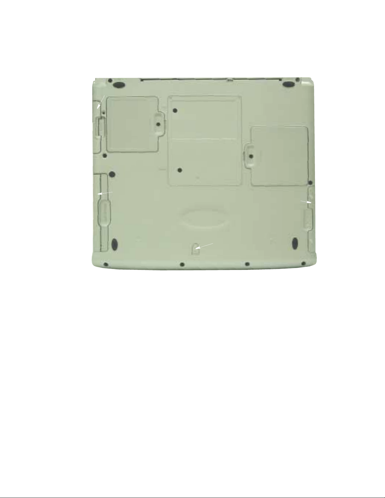
Bottom
Hard Drive
Mini PCI
Compartment
Flex Bay Compartment
Memory
Compartment
Battery Compartment
Flex Bay Latch
Introducing Your Computer 7
Page 18
Using Your Computer for the First Time
This section gives you detailed information on using your computer for the first time.
Installing the Battery
To install thebattery pack:
1. With the computer’s power off, close the LCD panel a nd t urn the computer over
so the bottom of the unit faces up.
2. Slide the battery compartment cover straight up and off the computer.
Insert the battery into the battery compartment,ensuring the correct
orientation so that the battery fits in its slot properly.
3. Slidethebatterypackinto the compartment.Makesurethebatteryisfully inserted
into the compartment.
4. Align the tabs on the battery compartment cover with the slots on the battery
compartment.
5. Push the cov er straight down until it snaps into place.
8 Users Manual
Page 19

Attaching the AC Adapter
Your computer runs on power from the battery in the computer or from an electrical
outlet. The first time that you use your computer, fully charge the battery by attaching
the power cord to the computer and to an electrical outlet.
All batteries lose their charge if they sit unused for an extendedtime period.
When not used, battery can discharge fully in 2 to 3 months. The battery may
have discharged in thetime it took for the computer to go from the fact ory to
you.
To attach the power cord:
1. Plug the AC adapter into the power connector on the back side of the computer.
2. Connect the power cord to the AC adapter and then to an electrical outlet.
AC Adapter
Power Connector
The battery startschargingassoon as you plugthepower cordintoanelectrical outlet.
The battery charges faster if the computer is turned off during charging.
If the battery is fully depleted and the computer is turned off, the battery charges in
about 3 hours. If the c omputer is turned on, the battery charges in about 5 hours. When
the battery is charging, the battery charge light is amber. When the battery is fully
charged, the light turns green.
See “Using Power Management Options” on page 52 for more information on using
your computer’s battery.
UsingYourComputer for theFirstTime 9
Page 20

TurningOntheComputer
To turn on the computer’s power for the first time:
1. S lide the LCD latch, located on the front of the cover to the right.
2. Lift up the cover.
3. Press and then release the powe r button.
The power light is on when the computer’s power is on.
Power button
Cover Latch
Adjusting the LCD Display
You may wish to adjust the LCD (Liquid-Crystal Display) when you begin using your
computer.ATFT(Thin-FilmTransistor)LCDdoesnot require adjustmentfor contrast
because the contrast is set to remain at maximum.
To adjust the LCD:
10 Users Manual
Power Light
Initial Computer Startup:
The first time you start your computer you willsee the operating system
registrationscreens.Simplyread eachscreen andfollowthesimple directions.
You must complete this process in order to use your computer. A tutorial is
provided if you require it.
Press <Fn+Right Arrow> to increase the display brightness.
•
Press <Fn+Left Arrow> to decrease the display brightness.
•
Page 21

Turning Off Your Computer
Prior to shutting down your computer ensure all of your data and current work are
saved. The system will ask if you wish to save any unsaved work, s aving your work
first will speed the shutdown process.
To turn off the computer, complete the following steps:
1. Click on the taskbar.
If you need to restart your computer after software (re)installation or because it is not
responding select the Restart option in step 3 below.
2. Click Shut Down Co mputer to display the shutdown popup window shown
below..
3. Click Turn Off to complete the shutdown sequence.
Power Off:
Ifthesystem does not poweroff,then pressandhold thepowerbuttonfor over
5 seconds. See “Using Power Management Options” on page 52.
Power Button Functions:
The power button has several functions other than just turning on and off your
computer,see “Using Power Management Options” on page 52.
You can also perform a soft boot by saving your files and pressing
<Ctrl+Alt+Del>to pop-up the “Windows Task Manager” window.
Click Shut Down > Restart.
You can perform a cold boot by pressing the power button for more than 5 seconds to
turn the computer off, waiting more than five seconds, and then pressing the power
button to turn the computer on. The system may perform some extra checks during the
restart.
Using Your Computer for the First Time 11
Page 22

Tips for Using Your Computer
The following information helps you avoid potential problems as you use your
computer:
Do not try to disassemble your computer. Opening the system chassis voids
yourwarranty.Onlyan authorisedmanufacturerservicecenter can replace or
add any parts inside the chassis.
Follow all the instructions and cautions in your computer user documentation.
•
The LCD has a polarized surface and can be damaged easily. To prevent
•
damage, avoid touching the screen.
Use only approved AC adapters, auto adapters, memory modules and other
•
options.
Becausea notebook computer is small and has restricted air flow around
•
components,it is more likely to overheat than a desktop computer.A fan inside
your computer runs when needed to help eliminate heat. Make sure the fan vent
on the left side of your computer is not blocked when you use the computer.
Occasionally check the vents and remove any accumulated dust on the outside.
Avoid using or storing the computer in extremelyhot or cold areas, such as a
•
car on a hot day. Keep the computer away from heatersand out of direct
sunlight. Exposure to e xcessive heat may damage computer components. If you
have left your computer in a hot place, let it cool down slowly to room
temperature (with the LCD panel open) before using it.
12 Users Manual
Do not remove the memory-module compartment door, or try to install a
•
memory module when the computer is on.
(For information on installing memory modules, see “Installing a Memory
Module” on page 67.)
Set up your computer work area to avoid physical strain. Sit with your back
•
straight and supported by your chair. Adjust your chair or work table so that
your arms and wrists can remain in a relaxed position, parallelwith the floor.
Avoid bending or twisting your wr ists as you work. Your hands should “f lo at”
slightly above the keyboard. Refer to a book on office ergonomics for more
information on setting up your work area.
Take frequent breaks from working at the computer to rest your eyes and
•
stretch your muscles.
Rememberto saveyour data files frequently and to make backup copies of your
•
files.
Page 23

Travelling with Your Computer
If you are travelling by air, follow these tips:
Take the computer with you as carry-on luggage. Do not check the computer
•
with your baggage.
Allow the computer and disks to go through the X-ray security devices. Do not
•
hand-carry disks through the walk-through metal detectors, which can cause
loss of data.
Please collect your computer immediately after X-ray scanning, this is a high
•
theft area for portable computers.
Make sure that the battery is charged or the power cord is easily accessible.
•
You may be required to turn on the computer for airport security personnel.
Be prepared to turn off the computerduring take off and landing.
•
Handling Spills
Do not s pill anything on your c omputer. The best way to avoid spills is to avoid eating
and drinking around your computer. If you do spill something on your computer, turn
off your c omputer, unplug it immediately, and do the following:
If you spill liquid on the keyboard, drain as much of the liquid from the
•
keyboard as possible. Be careful not to let the liquid drip onto the LCD p anel.
Allow the system to dry for several days before trying to use it.
If you spill liquid on an external keyboard or keypad, unplug it and drain as
•
much of the liquid as possible. Allow the keyboard to sit at room temperature
for a full day before trying to use it.
Sweet liquids leave a sticky residue that may jam the keyboard despite your
efforts to dry it.
If you spill liquid on the LCD panel, clean it immediately with a soft cloth and
•
denatured alcohol or a proprietary LCD screen cleaner. Do not use water,
window cleaner, acetone, aromatic solvent, or dry, rough towels to clean it.
Some liquids damage the polarized LCD screen. If your screen is damaged,
contact your authorized manufacturer’s service center for a replacement.
Using Your Computer for the First Time 13
Page 24

Storing the Computer for Long Periods
If possible, leave the power cord connected to the computer and an electrical outlet
when the computer is not in use. This extends the life of the battery and keeps the
battery fully charged.
If you will not be using the computer for a lo n g period of time (a month or more), you
shouldchargethe battery untilitis completelyfull.After you have doneso,remove the
battery from the unit.
14 Users Manual
Page 25

Using the Keyboard
Your computer has an 87/88-key keyboard. By pressingdesignated key combinations,
you can have access to all the key functions of a full-sized keyboard.
Function & Special purpose Hot Keys Imbedded Numeric Keypad
Function Key
Alphanumeric Keys
Althoughthe layout of the keys on your computer’s keyboard is different from
that on a desktop computer’s keyboard, the keyboard feels like a full-sized
keyboard when you use it.
Cursor & Screen Control Keys
The keys on the keyboard can be grouped into the following categories:
Full-sized Alphanumeric typewriter keys are arranged like a standard
•
typewriter keyboard and are used for text entry. The Windows keys on either
side of the spacebar open Windows menus and perform other special functions.
Function keys, when pressed together with the <Fn> key, enablespecial
•
functions.
Cursor and Screen control keys move the cursor. They may perform other
•
functions, depending on your software.
To clean the computer keyboard, use slightly damp cotton swabs. Scrubthe keys and
the surface around the keys.
Using the Keyboard 15
Page 26

Do not allow liquid to drip into the keyboardor you may damagethe keyboard.
Using the Numeric Keypad
Your keyboard includesa numerickeypad, which is a group of keys thatyoucan set to
type numbers and mathematical symbols, such as the plus sign. A number or symbol
on the right corner of each keypad key shows its numeric function.
Num Lock LED
Press <Num Lock> to turn on the embedded numeric keypad. The numeric functions
of the keypad a re enabled and the Num Lock light turns on.
Whilethenumeric functionsare enabled,youcan temporarilyreturn a keytoits normal
function by pressing <Fn> and the key. For example to type the letter m, press
<Fn+m>.
To turn the numeric keypad off, press <Num Lock> again. The Num Lock light turns
off.
16 Users Manual
Page 27

Using Special Function Keys
The <Fn> key activates special functions when it is pressed in combination with
another key.
Table 2. Description of Special Function Keys
<Fn> Key
Combination
<Fn+F1>
<Fn+F2>
<Fn+F5>
<Fn+F6>
<Fn+F7>
<Fn+F8>
<Fn+F9>
<Fn+F10>
<Fn+F11>
<Fn+F12>
<Fn+Right
Arrow>
<Fn+Left Arrow>
Function
Print screen:
program.
System request:
CRT/LCD:
simultaneous display on both the LCD and the external monitor.
Gauge:
The gauge closes in a few seconds, oryou can press <Esc> to closethe gauge.
(See “Monitoring the Battery Charge” on page42 for more information on the battery
gauge.)
KeyLock:
password and press <Enter>to unlock the keyboard. The <Fn+F7> key combination
has no effect unless a password is enabled in System Setup. The Num Lock, Caps
Lock, and Scroll Lock lights blink when the keyboard is locked.
Mute:
Volume down:
Volume up:
Rest:
press the power button. (See “Using Power Management Options” on page 52 for
more information about the rest mode.)
Scroll:
down while the cursor position does not change. Pressing <Fn+F12> again turns off
the scrolling function.
Brightness up:
Brightness down:
Takes a picture of the open screen, which you can paste into the Paint
Reserved for use in software programs.
Switches the display between the LCD, the external monitor, and
Displays the battery gauge in the upper-right corner of your screen.
Locks the keyboard and activates password protection. Type your
Turns the audio output on and off.
Decreases the audio volume.
Increases the audio volume.
Puts the computer into Suspend mode. To resume normal operation from rest,
In some applications, sets the cursor-control keys to scroll the page up or
Increases the LCD brightness.
Decreases the LCD brightness.
When you press a function key combination,the system sound may be
temporarily muted.
Using the Keyboard 17
Page 28
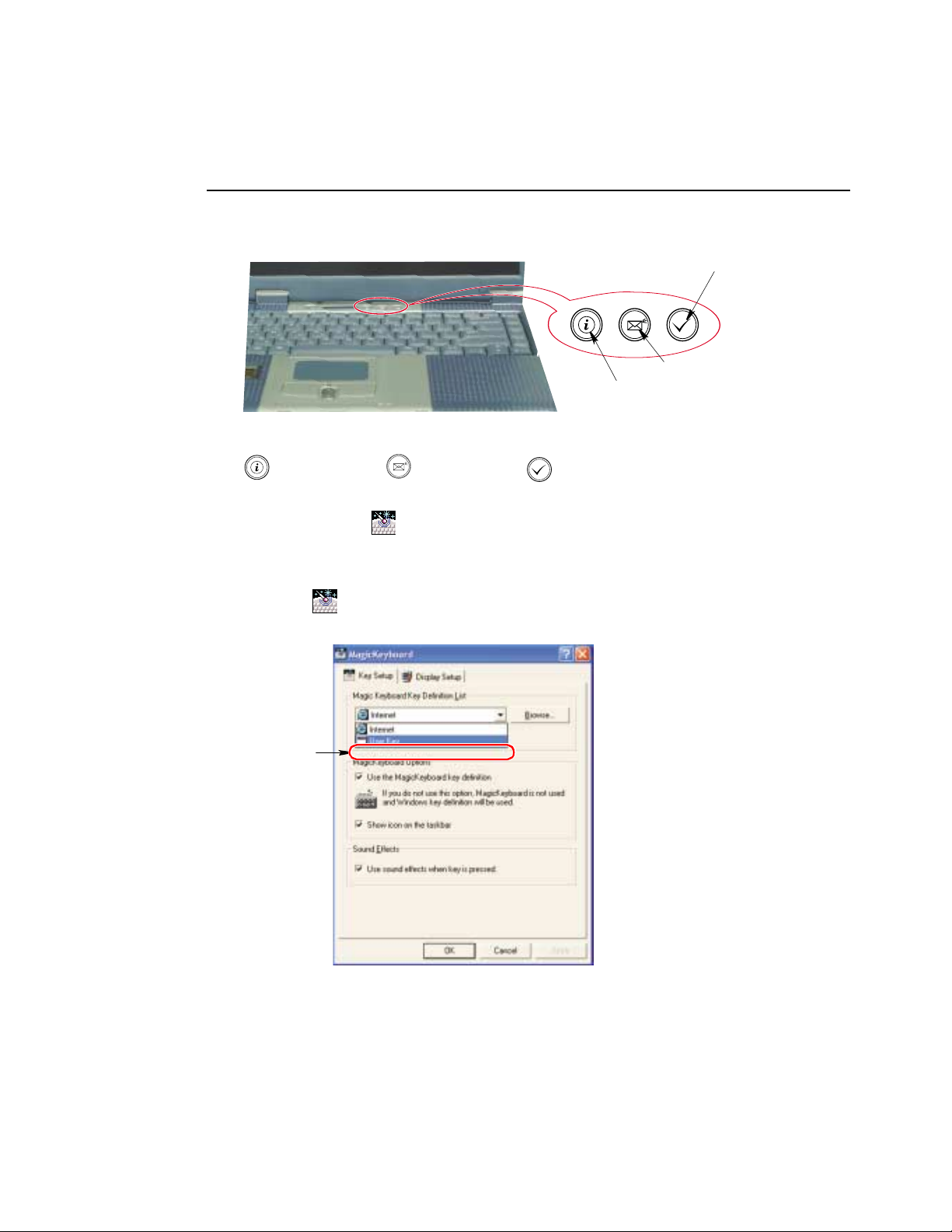
User Defined Buttons (Magic Keyboard)
You may program the three buttons to the left of the power button to start any program
you have installed on your computer.
User defined program
Outlook Express
Internet Explorer
The default s ettings for these buttons are:
Internet E-Mail - Outlook User Programmable
To reprogram the Magic Keyboard, follow the steps below:
1. Double-Click icon on the Windows taskbar
-or-
1. Click Start > ControlPanel > OtherControl Panel Options.
2. Click icon.
3. Select User from the drop down menu.
User
18 Users Manual
Page 29

4. Use the Browse button to locate the program you wish to assign to the Magic
Keyboard User programmable button.
5. Click on your program choice to select it.
6. Click OK.
7. Click OK to close window and complete programming the Magic Keyboard.
Button Programming Notes:
You may also program the internet button to open your prefe rred internet
browserprogramand/orprogramtheE-Mailbutton fortheE-Mailprogramyou
wish t o use.
Using the Keyboard 19
Page 30

Using the Touchpad
Your computer is equipped with a touchpad, which is an integrated-pointing device
that is used to perfor m standard mouse functions. The touchpad i s an advanced and
reliable pointing device that works with a touch of your finger.
Touchpad
Mouse buttons
Scroll button
Press on the touchpad gently. The t ouchpad responds to light pressure.
Table 3. Using the Touchpad
Action Process and Comment
Click/Tap
20 Users Manual
Process
Depress the touchpad left button and release or position the pointer
over the object and Quickly tap the touchpad once with your finger.
This action is called
Comment
This will cause a process to begin or select an object on the screen.
clicking
.
Page 31

Action Process and Comment
Double-Click/Tap
Click-Hold
Right-Click
Scroll up
Process
Quickly click the left touchpad button twotimesor position the pointer
over the object and Quickly tap thetouchpad twice with your finger.
This action is called
Comment
This will cause a process to begin or open a file folder.
Process
Depress the left touchpad button and do not release.
Comment
This is used to move/drag objects to new locations. See “Drag (Move)”
on page 22.
Process
Position the pointer over the object. Quickly press and release the right
button once.
This action is called
Comment
This is usually used to obtain information about an object or access a
short cut menu.
Process
Place your finger on the top half of the button to scroll up the current
window.
Double-clicking
Right-clicking
.
.
Scroll down
Comment
Moves the current window down.
Process
Place your finger on the bottom half of the button to scroll up the current
window.
Comment
Moves the current window up.
PS/2 Mouse:
You may change the setup in Setup > Advanced Menu
Disabledprevents both the t ouchpad and externalPS/2 port from functioning.
Single mouse (default) enables the external PS/2 port or t he touchpad, and
external PS/2 port has priority. Dual Mouse allows the use of both the
touchpad and PS/2 port.
Using the Touchpad 21
Page 32

Drag (Move)
To move a window on the desktop, complete the following:
1. Click the window title bar or icon in the bottom of the window which you want
to drag using the touchpad.
2. Press the left touchpad button and hold it.
3. Drag the window using the touchpad.
Cursor in Windows
Title Bar
Drag your finger to
move the window
Click theWindow
Title Bar and Hold
22 Users Manual
Area or M ultiple item selection:
The drag function may be used to select an area or multiple items in an area
by clicking in one area and then dragging to create a selection window. The
items inside the wi ndow will be selected.
Page 33

Reading the System Status Lights
System Status lights showthe status of computer functions.
Table 4. System Status Lights
LED Name Function
Num Lock Changes a portion of the keyboard to a numeric keypad.
Caps Lock Changes all alpha or letter input into capital letters.
Scroll Lock Scroll lock in certain software.
Drive Access Using the Disk Drives.
E-mail Alert The Light comes on when e-mail arrives.
Power Green - System power on.
Battery
Status
See “Using the Numeric Keypad”on page 16.
No changes occur to numeric and special keys.
Blinking Green - HDD is being accessed
Blinking Amber -FDD orCD-ROMis beingaccessed
To use this function, you must register an E-mail Account in the
Register E-mail Account
Select: Start > All Programs > StartUp > Internet Launcher.
Blinking - Standby mode.
Green - No battery packinstalled/battery fully charged.
Amber - Charging.
window. To register an E-mail account
Reading the System Status Lights 23
Page 34

Connecting Peripheral Devices
The connectors on your computer enable you to attach peripheral devices to the
computer.
Turn off your computer beforeyou connect a peripheral device. Connecting a
peripheraldevice with your computer turned on may seriously damage the
device or your computer.
TV-Out Port
Headphone Jack
Battery
SPDIFIn Jack
LineInJack
Microphone Jack
PS/2 Port
Modem Port
24 Users Manual
Parallel
Printer Port
Parallel
Printer Port
1394 Port
USB Ports
Serial Port
External Monitor Port
Page 35

Connecting to the Internet
Thissection explainshow to connectyouto the internet.For detailsonhowto establish
the connection contact the Internet Service Provider [ISP] or system administrator
[SysAdmin].
Using the Modem
Install the Modem cable by s imply plugging the cable into the slot in the back of the
computer.
Modem Cable
(Minimum 26 AWG)
1. Contact your Internet Service Provider to obtain information or CD required to
make the connection in your area.
2. After the cable is connected create a “Dialup” connection by clicking
Start > Control Panel > Network and Internet Connect ions.
3. Click Set up or change your Interne t connection>Setuptostartthe connection
wizard.
4. Follow the instructions in provided in the Make New Connection wizard.
Connecting to the Internet 25
Page 36

Precautions Before Use
Country Selection
Country Selection:
Because your computer is very mobile you must
country you are callingfrom
experience connection problems.
is selected correctly, otherwise you may
To changethecountry selection proceed as follows:
1. Start > Control Panel > Network and Internet Connections.
2. Click Phone and Modem Options.
3. Click on the connection you wish to edit in the Locations: box.
4. Click Edit in the Dialing Rules Tab
5. Select the Country/region you are c alling from in the General tab.
6. Click OK to close the "Edit Locations" box.
7. Click OK to close “Phone and M odem Options” box.
Digital Phone Lines:
If you connect the modem to a digital phone line (such as a company
4-wire system), the modem may be damaged.
ensure you select the
DOS support
Using the Modem o n a PBX system
If you use a Windows Communication Program:
1. Click Start > Control Panel > Network and Internet Connections.
2. Click Phone and Modem Options.
3. Click Properties in the Modems tab section.
4. Check off “Wait for dial tone before dialing” check box in theModem tab
5. Click OK to close the dialog box.
6. Click OK to close “Modem Properties” dialog box.
26 Users Manual
Windows XP: Does not support pure DOS mode
•
support a DOS box in Windows. So you cannot use a
communication application which runs under DOS.
section.
and the modem does not
Page 37

If you use a simple terminal program (i.e. hyper terminal):
Type the “ATX3&W” or “ATX3” command as an initialization command.
MODEM Notes:
1. In ordertousethe 56Kfeature,be sure tocheckif the standardssupported
by the on-line service provider and the modem are identical.
2. If you use a PBX phone system, you can not connect using the 56K mode.
3. Internationally connected calls will be limited to 33.6K (Max.)
Using the LAN
You may connectto the network using eitheraLAN cable or by establishinga wireless
connection.
Cable Connection
Install the L AN cable by simply plugging the cable into the slot in the back of the
computer.
Your computer’s LAN adapter is ready to use for most situations, however if your
system does not have a DHCP server or you wish to personally configure your LAN
connection,proceed as outlined in “Configuring Network Environment” below.
Network Pr otocols:
Youmayneed to consultyourSysAdmini f theirnetworkprotocolsandsettings
are required for your LAN environment.
Configuring Network Environment
Configure the Network Adapter as follows:
1. Click Start > Control Panel > Network and Internet Connections
Connecting to the Internet 27
Page 38

2. Click icon (Ne twork Connections)
3. Double-Click the icon (Labeled Local Area Network)
4. Select Internet Protocol (TCP/IP)in the “This connection uses the following
items:” box.
5. Click Properties. The TCP/IP Properties window opens.
6. Click “Use the following IP address” in the General tab
7. In the “Use the following IP address” box, enter yourIP address : , subnet mask:
8. In the “Use the followingDNS server addresses”box, Enter yourPreferredDNS
9. Click OK when you finish the TCP/IP set-up.
Wireless Connection
28 Users Manual
Step8
and Default Gate way:.
server: and Alternate DNS server:.
Page 39

Using the Flex-Bay
Your computer includes the Flex-Bay, a peripheral bay that can hold one of the
following devices:
CD-ROM drive: shipped with some computers and also available as an option.
•
DVD-ROM: shipped with some computers and also available as an option.
•
Optional secondary hard drive: available as an option for your computer.
•
Superdisk LS-120: available as an option for your computer.
•
If your operating system is Windows, you can use the SwapBay Utility to hotswap the devices. If you do not use Windows, make sure that the computer’s
power is off before you remove or install any devices.
Remove/Install a Flex-Bay Device - Power On
You can use the Softex B ay Manager utility to hot-swap your devices in the flex-bay.
To start the Softex Bay Manager utility:
1. Click Start > ControlPanel > OtherControl Panel Options > Softex Bay
Manager.
-or-
2. Double-Click the SwapBay icon in the windows taskbar.
To remove a device:
1. Start the SoftexBay Manager Utility.
Using the Flex-Bay 29
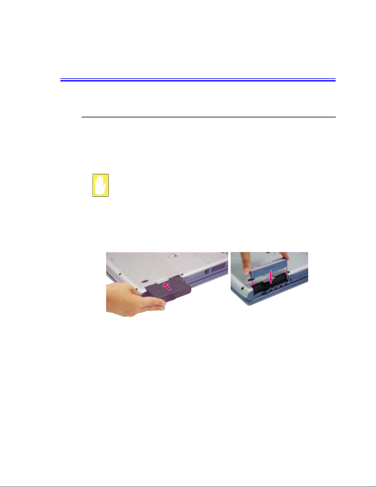
Page 40

You do not have to turn the computer over or tip it on its side to change
devices.Simply tilt the computer u p at the front about 10 cm and locate the
Flex-Bay latch. See Figure below for th e location of the Flex-Bay latch. The
computer in the figure is tilted on its side for clarity.
Flex-Bay Latch
2. ClickRemove / Swap. A Device Change popupwindowstating, “Please waituntil
the system processes the device change” appears then another popup window
appears and says, “Please remove or swap your bay device(s) now and press OK.”
3. Tilt the computer up & locate the smart bay latch.
4. Slide and hold the device latch toward the front of the computer.
5. Slide the device out.
6. ClickOK. Themessage“Please waituntilthe systemprocessesthedevice change”
7. Click OK to close the Softex Bay Manager Utility.
To insert a device:
1. Open the Softex Bay Manager Utility.
2. ClickDevice Insert.Apopupwindow appearsstating “Pleaseinsertyourdevice(s)
30 Users Manual
appears again.
You do not have to turn the computer over to change devices. Simply tilt the
computer up and locate the Flex-Bay latch. See “Bottom” on page 7 for the
location of the F lex-Bay latch.
into the bay now and click OK.”
Page 41

3. Insert the device.
4. Click OK to allow your computer to detect the device. The message “Please wait
until the system processes the device change” appears.
5. Click OK to close the Softex Bay Manager Utility.
Remove/Install a Flex-Bay Device - Power Off
RemoveaDevice:
1. Turn the computer’s power off.
2. Close the LCD panel, a nd turn the computer over so that the bottom of the unit
faces up.
3. Tilt the computer up & locate the smart bay latch.
4. Slide and hold the device latch toward the front of the computer.
5. Slide the device out.
Install a Device:
1. Turn the computer’s power off.
2. Carefully slide the device into the bay.
3. Push the device in until it is flush with the chassis and t he Flex-Bay latch snaps
intoplace.Yourcomputer’s operatingsystemautomaticallyrecognizes the device
in theFlex-Bay andconfigures yourcomputeraccordinglywhenpoweris restored.
Using the Flex-Bay 31
Page 42

Using the Disk Drives
Using the Floppy Disk Drive
Your computer comes with a 1.44 MB, 3.5-inch, floppy drive.
To use a floppy disk in your computer, insert it into the floppy drive.
Floppy Disk Eject Button
To remove a floppy disk, press the floppy disk eject button on the front of the floppy
drive.
To protect the data on your floppy disks, follow the manufacturers guidelines.
32 Users Manual
Page 43

Using the CD/DVD-ROM Drive
Compact discs are designed so that you can easily insert one into the computer when
you need it, a nd thenremove it. See “Using the Flex-Bay” on page 29 for information
on installing the DVD-ROM drive into the computer.
DVD Notes:
A DVD player is a factory optionandif you ordered this optionyou will have to
install the provided DVD software to view the DVD Title.
1. Press the button on the CD-ROM or DVD-ROM drive, and the tray slides out.
(Do not lean on the tray; because it will not support much weight.)
CD/DVD Drive Warnings:
Do notplace reflective objects other than the CD/DVD disks in the disk slot
because of possible hazardous laser emissions. The laser beam used in this
CD/DVD-ROM drive is harmful to the eyes. Do not attempt to disassemble the
CD/DVD-ROM drive. Refer servicing to your authorized service center.
Do not touch the CD/DVD lens, doing so may damage the device.
CD/DVD Precautions:
The tray may be stuck, in which casestraighten out a paper clip, insert
it into the Emergency Eject hole in t he front of the CD/DVD-RO M and push it
until the tray ejects.
A LED on the drive tray is on when the computer is reading from a CD. Do not
remove a disc when this LED is on.
To clean a CD/DVD, wipe from the center outwards with clean and dry cloth.
Remove the CD/DVD when the drive activity LED i s off.
2. Insert a CD/DVD, label side up (or remove a disc, if you have finished using it).
Using theDiskDrives 33
Page 44
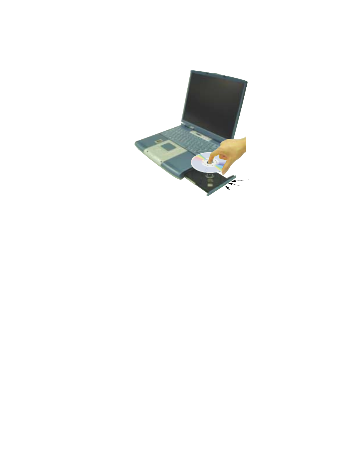
3. Pushthetrayingentlytoclosethedrivetray.
Emergency eject button
Eject Button
CD-ROM Light
Install and/or start a CD-based program as you would run a program on a floppy disk.
34 Users Manual
Page 45

Working with PC Cards
When you install PC Cards, you cad add a multitude of functions to your notebook
computer similar to those found on add-in boards for desktop computers. There are
many PC Cards on the market, the supported PC Cards are listed below:
Input/output, such as modem, network, video capture, and SCSI cards.
•
Storage, such as hard drive and flash memory cards.
•
Your computer includes the following PC Card support:
Two PC-Card slots: You can install Type I, II, or III cards in the slots.
•
TYPE III Cards:
Type IIIcardsarethickerthanTypesIand II. If you install a Type III card in the
bottom slot, you cannot install a card in the top slot.
CardBus hardware and software: CardBus enables the computerto use 32-bit
•
PC Cards. Windows XP supports 32-bit and 16-bit PC Cards.
Zoomed video: Both PC Card slots and the video chip on your computer
•
support zoomed video. When you install a zoom video PC Card in the upper or
lower slot, data can be transferred directly from the PC Card to video and audio
systems without going through the microprocessor.Video conferencing and
real-time multimedia devices, such as video cameras, are supported by zoomed
video.
Maintaining PC Cards
To maintain your P C Cards, follow these guidelines:
Keep cards away from excessive heat, direct sunlight, and liquids.
•
Do not drop, bend, flex, or crush cards when handling.
•
Keep dust, magnets, and static electricityawayfrom PC Cards.
•
When a card is not in use, carry it in its protective carrying case.
•
Some PC Cards include cables that extend from the back of the cards. Be
•
careful not to bend or put excessive strain on these cables.
Working with PC Cards 35
Page 46

Using PC C ards
To insert a PC Card into a slot:
1. Push the slot door in with the PC Card.
2. Align the card with a slot and insert the card into the slot until it locks in place.
PCCardEjectButtons
And / Or
PC Cards: (Examples)
Insert PC Card with product
information facing up
Windows automatically assignsc omputer resources (such ascommunicationportsand
memory addresses) to a PC Card installed in your computer.
To remove a PC Card from your computer:
1. Click icon on the taskbar.
2. Select the card currently in use, and clickthe Stop button.
The eject button for the card slot operates in two steps, therefore to remove a PC Card:
3. Push the eject buttononce to pop it outward then push the eject button again to
4. Pull the card out of the PC Card slot.
36 Users Manual
Use the following procedures to remove PC Cards, or you may lose data that
is being stored to a card.
eject the card.
Page 47

Multi Media Functions/Equipment
Media Player
You can play video and audio CD files with the Windows Media Player, as well as
watching TV, video and listening to the radio through internet. The on-board audio
hardware and software of your computer enable the computer to play audio/video
compact discs. The instructions to play a video C D-ROM are the same as the
instructions for the audio CD below. If you wish to do so, you can attach external
speakers to the Headphone jack.
Playing a Audio/Multimedia CD
To play an CD follow the instructions below:
1. Insert a compact disc into your CD-ROM drive.
2. Press the button on the CD-ROM drive to open the CD-ROM device.
3. Insert a CD, label side up.
4. Carefully push the tray in to close the drive tray. The Windows Media Player
button appears on the taskbar if not already there, and the music begins to play. If
the disk does not play click Start > All Programs > Accessories >
Entertainment > Windows Media Player.
CD LED On:
A LED on the drive tray is on when the computer is reading from a CD. Do not
remove a disc when this LED is on.
Removing the Audio/Multimedia CD
To remove the CD follow the instructions below:
1. ClickStart> All Program s > Accessories > Entertainment > W i ndo ws Media
Player to open the Windows Media Player window, if not already open.
2. Click Stop in the Windows Me dia Player window or simply close the Windows
media player.
3. Pressthebutton on yourCD-ROMdrive. Thedrivetray opens andyou canremove
the CD from the CD-ROM drive.
4. For m ore information on playing compact discs, see the Help menu in the
Windows Media Player window.
Multi Media Functions/Equipment 37
Page 48

Dolby Stereo
Your computer supports Dolby S tereo through a SPDIF connector, located next to the
volume control wheel on the left side of the computer. You must have a 3.5mm
(mono)- to RCA cable to use this port.
Volume Control
Using the Wheel Volume Control
Simply turn the wheel locatedon the left side of the computer.
Need New Picture
Using the Keyboard
Changing the volume with your keyboard.
Use <Fn+F9> to decrease the volume or <Fn+F10> to increase the volume.
Using the Volume Control Icon
Double-Click iconin the active program tray. TheVolume Control window pops
up. Use this window to adjust the volume. You can p op up a simple volume slider by
a single click icon.
Movie Maker
You caneditaudio andvideodata usingthis MovieMaker includedwith WindowsXP.
It is also possible to make a slide show with each frame or picture.
To start the program:
Click Start > All Programs> Accessories > W indows Movie Maker.
38 Users Manual
Wheel Volume Control
Page 49

Please refer to the on-line help manual to operate the Windows Movie Maker.
Multi Media Functions/Equipment 39
Page 50

Using the Battery
Your computer uses a s mart rechargeable Lithium-ion (Li-ion)batterypack for power
when the AC adapter is not attached to an electrical outlet. The smart battery gives a
accurate measurement of the current battery capacity which helps extendoperating
time by enabling effective power m anagement in operating systems that take
advantage of the accurate information supplied by the battery.
Charging the Battery
Your computer’s battery starts chargingautomatically when you connect the power to
thecomputer andtoan electrical outlet.If thecomputer isoff,thebattery chargesfaster
than if the computer’s power i s on.
Approximate charging times for the Li-Ion battery are
3 hours with the computer off.
•
5 hours with the computer on.
•
While the battery is charging normally, the battery charge light on the computer is
amber. When the battery is fully charged, the light changes to green.
When you use a new battery pack for the first time or use a battery after a long period
of storage, the initial battery life is shorter than normal. Normal b attery life resumes
after a few discharge-recharge cycles.
Follow these rules for charging your battery:
40 Users Manual
A battery normally discharges power when not used for long periods of time.
•
Be sure to recharge the battery every two months when it is not in u se.
Make it a practice to discharge your battery fully before r echarging the battery.
•
This can help extend the life of the battery.
Do not attempt to charge the battery in temperatures of under
•
All batteries eventually wear out and lose the ability to hold a charge. You may
need to replace your battery pack after a year of average usage.
5oCorover35oC
Page 51

Safely Using the Battery
Follow these guidelines to safely use the battery:
Turn off your computer and unplug it if you accidentally:
•
– Expose the e quipment to liquid.
– Drop, jar, or damage the computer.
Use only approved battery chargers.
•
Do not disassemble the battery, heat it above 100°C, or burn it. The battery
•
used in this computer m ay cause a fire or chemical burn if mistreated.
Your computer's rechargeable battery may be considered hazardous waste. If
•
you replace your battery with a new one:
– Keep the old battery out of the reach of children.
– Dispose of the old battery promptly.
– Make sure that you follow all local requirements when you dispose of the
old battery.
Removing the Battery
Your computer comes with the battery pack inserted in the computer.
To remove the battery from the computer:
1. Turn the computer’s power off.
2. Close the LCD panel, a nd turn the computer over so that the bottom of the unit
faces up.
3. Slide the battery compartment cover straight up and off the computer.
4. Grasp the tab on the battery a nd pull the battery out of the compartment.
Using the Battery 41
Page 52

Installing the Battery
To install thebattery pack:
1. With the computer’s power off, close the LCD panel a nd t urn the computer over
so the bottom of the unit faces up.
2. Slide the battery compartment cover straight up and off the computer.
Insert the battery into the battery compartment,ensuring the correct
orientation so that the battery fits in its slot properly.
3. Slidethebatterypackinto the compartment.Makesurethebatteryisfully inserted
into the compartment.
4. Align the tabs on the battery compartment cover with the slots on the battery
compartment.
5. Push the cov er straight down until it snaps into place.
Monitoring the Battery Charge
Battery life is a ffected by factors such as the power-management settings in System
Setup, the applications you use, and the brightness settings of the L CD. Under normal
usage, the battery charge lasts approximately 3 hours.
You can monitor the chargeofthebatterypackinstalled in yourcomputer by using the
Power Meter or Battery Gauge.
42 Users Manual
Battery life estimates are subject to variation. The actual life of your battery
may be less than the estimates given in the manual.
Page 53

Power Meter
The Power Meter displays the charge of the batteries and the current source of
computer power, AC or batteries. You may monitor the battery charge or usage by
using the “Power Meter”. To access the power meter click icon on the task bar or
click Start > Control Panel > P ow er Options > Power Meter tab.
The Power Status icons shown below are displayed
during Battery Charging Operations
At ~15% and 10% remaining battery power the
current power source and the battery Icons
respectively change to the icon shown below and
you should follow the instructions in “Battery
Youmayalso checkbatterychargebymoving thecursortothe icon,asmall dialog
box will display the % of charge.
Warnings” section below
Using the Battery 43
Page 54

Battery Gauge
Youmaydisplaythebattery gaugewhile you areinany programbypressing <Fn+F6>.
While the battery gauge is being displayed, all keys except < Esc> are disabled. The
battery gauge is only displayed for a few seconds.
The battery gauge will display three of the four icons shown below in the following
order: Power Source, Save Level then Battery Level.
Power Source:
Indicates that the computer is powered by the AC a dapter.
•
Indicates that the computer is powered by the battery.
•
Battery Level:
The top/right section indicates the approximate amount of the
•
primary battery charge remaining.
44 Users Manual
Page 55

Battery Warnings
If the battery charge is low (about 10%) you have approximately 5–10 minutes of
battery life left. You should:
Save your work and,
•
Connect the power cord to the computer or turn off the computer and i nstall a
•
fully charged battery.
You can adjust the battery alarm features by using the operating systems power
management program (Start > Control Panel > Power Options in Windows).
If you cannot run your computer from the battery and the battery will not charge when
you attach the power cord, the problem may be that:
The battery temperature is below 10°C or over 32°C. If you think the battery
•
temperature is too hot or too cold, turn off the computer, remove the battery,
and let the battery reach room temperature. Then try charging the battery again.
The battery is defective. Replace the battery with a new battery.
•
Using the Battery 45
Page 56

Using System Setup
The System Setup program enables you to configure your computer hardware and s et
security and power-savings options. The settings you choose are stored in batterymaintained CMOS memory that s aves the information even when the computer’s
power is turned off. When your computer is turned back on, it is configured with the
values found in this memory.
Run System Setup if you get a message prompting you to run the program. You may
also want to run System Setup, particularlythefirsttimeyouuse yourcomputer,toset
the time a nd date, use security or power-management features, or alter the settings of
other features.
Your computer’s version of System Setup may not include all t he fields listed
here or may include additional fields. Field names and order of appearance
can vary according to the version of the BIOS (basic input/output system) on
your computer.
Starting System Setup
To start System Setup,turn on your c omputer and then press <F2> when prompted.
The System Setup screen appears.
The topoftheSystem Setupscreenhasa menu bar with the selections listedin Table 5.
To open amenu,usetheleft or right arrowkeystoselect the menu nameandthenpress
<Enter>.
46 Users Manual
Table5. System Setup Menus
Menu Function
Main Changes the basic system configuration.
Advanced Configures advanced features on your computer.
Security Enables security features, including passwords and
backup and virus-check reminders.
Power Configures power-management features.
Boot Specifies the order of boot devices andconfigures boot
features.
Exit Specifies how to exit System Setup.
Page 57

Table 6. System Setup Navigation Keys
Navigation Key Alternate Key Function
<F1> <Alt+H> Displays the General Help window.
<Esc> Exits the current menu.
<Left Arrow> and
<Right Arrow> keys
<Up Arrow> and
<Down Arrow>
keys
<Tab> Moves the cursor forward through the cells for a highlighted
<Tab+Shift> Moves thecursor backwardthrough thecells for a highlighted
<Home> <PgUp> Moves the cursor to the field at the top of the window.
<End> <PgDn> Moves the cursor to the field at the bottom of the window.
<F5> <-> Scrolls backwards through the options for the highlighted field.
<F6> <+> or <Space> Scrolls forward through the options for the highlighted field.
<F9> Sets the parameters for the current menu to their default
<F10> Sets the parameters for the current menu to their previous
<Enter> Executes commands or opens a submenu.
Keypad arrow
keys
Keypad arrow
keys
Selectadifferentmenu.Pressing<ESC>attheMainmenu
brings you to the Exit menu.
Move the cursor up and down between fields.
field.
field.
values.
values.
UsingSystem Setup 47
Page 58

Changing Booting Priority
The Boot menu in System Setup enables you to select the booting deviceand to set
booting options.
Boot Device Priority field enables:
You to s elect the order in which the computer attempts to boot from different devices.
The fieldhasFour(4)options:DisketteDrive,RemovableDevices, Hard Drive and
ATAPI CD/DVD Drive.
To change the booting device priority, choose the device positions by completing the
following:
1. At startup, press < F2> to open System Setup
2. Use <Right Arrow> or <Left Arrow> to select the Boot menu.
3. Press <Enter> in the Boot Device Priority field.
4. Highlight the option with the <PgUp> or <PgDn> keys.
5. Use <-> or <+> keys t o m ove the boot device up or down in the list of options.
6. Press <Esc> to return to the Boot m enu.
The default s ettings are:
1. Diskette Drive, 2. Removable Devices, 3. Hard Drive. 4. A TAPI CD/DVD Drive.
7. Press <Esc> to go to the exit menu.
8. Select E xit Save Changes, press <Enter>.
9. Press <Enter> again to restart the computer.
48 Users Manual
If you want to start the system using a bootable CD, change the CD-ROM
Drive to be the first priority and make sure that Auto is set in the Type field of
the Secondary Master Submenu at Main page.
Page 59

Using System Security
This section describes the security options provided with your computer. Your
computer has two types of security. The first is the standard BIOS security which is
fairly standard on all computers. The secondis a more advanced Biometric security
system which reads your fingerprint(s). In this case you d o not have to wo rry about
your password being lost or stolen.
Bios Security
The BIOS security methodology is explained below.
System Passwords
The computer provides two levels of password security: administrative-level
(supervisor)and user-level(user). Eitherpassword preventsunauthorized accessto the
computer. The supervisor password enablesfullaccesstoall System Setup fields. The
user passwordenables full accesstoonly the SetUser Password and Passwordonboot
security fields and read access to all other System Setup fields.
If m ultiple users have access to the computer (such as in a network environment), a
supervisor password can prevent unauthorized access to certain security options.
Choose the type of password securitythat is appropriate for your work. If you want to
set a user password, you must set a supervisor password first.
If You Forget Your Password
It is very important that you do not forget your password. If you do, you cannot access
your system. Write your password down and keep it i n a safe place. If you do forget
and cannot find the written note, please contact the Samsung Helpline. Please have
your receipts available to verify the type and model of your computer. You may be
charged for password re moval.
Creating a Password
To create a password:
1. At startup, press < F2> to open System Setup.
2. Use the <Right Arrow> key to select the Security menu.
3. Use the <Down Arrow> key to sel ect Set Supervisor Password or Set User
Password.
4. Press <Enter>.The Set Password dialog box appears.
Using System Security 49
Page 60

5. Type a password of up to seven characters. You can enter letters or numbers, but
you cannot use the function keys, such as <Shift>. Your computer do es not
distinguish between capitalized and lowercase letters inyour password. As you
type the password, the cursor moves but your password does not a ppear on the
screen.
6. Press <Enter> after you have typed your password. The computer prompts you to
reenter your password for verification.
7. Type your password again and press <Enter>. A message appears telling you that
the changes have been saved. Press <Enter> again to return to the Security menu.
8. Press <Esc> to go to the Exit menu.
9. Select Exit Saving Changes, press <Enter>, and press <Enter> again to restart the
computer.
Deleting a Password
To delete the password:
1. At startup, press < F2> to open System Setup.
2. Type your password when prompted and press <Enter>.
3. Use the <Right Arrow> key to select the Security menu.
4. Use the <Down Arrow> key to sel ect Set Supervisor Password or Set User
Password.
5. Press <Enter>. The computer prompts you to enter the current password.
6. Press <Enter>. The computer prompts you to enter a password. Do not type
anything.
7. Press <Enter>. The computer prompts you to re-enter the password. Do not type
anything.
8. Press <Enter>. A message appears telling you that the changes have been saved.
Press <Enter> again to return to the Security menu.
9. Press <Esc> to go to the Exit menu.
10. Select Exit Saving Changes,press<Enter>, and press <Enter> againto restart the
computer.
Requiring a Boot Password
After youcreateasupervisor or user password,you can enablethecomputer to prompt
for a password each time it starts.
To enable the prompt, select the option Enabled in the Password on boot field in
System Setup. For more information about thePassword on boot field.
50 Users Manual
Page 61

Locking the Keyboard
The keyboardlockenablesyou to protect your system when you walk away from it for
a t ime. To use the keyboard lock, you must first enable a password through System
Setup.(See “CreatingaPassword” onpage49for instructions.Tolock your keyboard,
press <Fn+F7>. To unlock your keyboard, type your password and press <Enter>.
Biometric Security
The Biometric s ecurity methodology is explained below.
Using System Security 51
Page 62

Using Power Management Options
Your computer includesPowerManagementoptionsthatcan help the battery charge
last longer and extend the life of the battery. Power-management options will slow
down or shut off system components when the components are not being used.
Power management may slow down system performance. Your computer runs fastest
with the power cord attached,when power management is disabled.
In the next sections, basic and advanced methods of power management will be
discussed.
Intel® SpeedStep™
There are two methods to change the Intel® SpeedStep™setting, they are explained
below.
BIOS Interface
Intel® SpeedStep™will control the CPU speed on your system according to the kind
of power supply as part of power saving management.
To use this function, your system must me et th e conditions below:
Intel® SpeedStep™supporting CPU
•
To start or verify Intel® SpeedStep
1. Start your computer and press <F2> to enter BIOS setup.
2. Go to System P ower menu
3. Select the Intel® SpeedStep
4. Press <F10> to save and exit system setup
52 Users Manual
Application for Intel® SpeedStep™function
•
BIOS Support
•
™
is operational complete the following:
™
field and select one of the following options:
Performance: The CPU runs at high speed regardless of the type of power
•
supply.Battery life is the shortest.
Battery: The CPU runs at low speed r egardless of the type of power supply.
•
Battery life is the longest.
Automatic: The CPU speed is changed according to the type of power supply.
•
(It is recommended you select this option)
Disabled: Disables this function
•
Page 63

Task Bar Interface
You may change the Intel®SpeedStep™settingby doubleclickingon the iconon
the task bar. This will open the Intel
® SpeedStep
TM
technology popup window.
The following will explain each of the above numbered items.
1. This optionwill allow automaticor “Ask me beforeautomaticallychanging”CPU
speed c hanges based on the power supply source.
2. Each power supply optionhasa dropdown window and wh en youclickonthe
arrow the drop down selector appears, displayed in numberabove. These
options allow the user to set operation of the CPU based on the power supply
source.
3. These are the available options for each type of supplied power.
4. The Intel
that are self explanatory.
®
SpeedStepTMtechnology [Advanced] popup window has 3 options
Using Power ManagementOptions 53
Page 64

Basic Power Management Schemes
This section discusses the basic schemes of power manageme nt when the computer is
operating on battery power or using AC power.
Standby vs. Hibernation
Standby unlike hibernation mode does notstore unsaved information on your
hard disk;it'sstoredonlyin the computer memory.If there is an interruption in
power, the information is lost. So before putting your computer on standby,
you should save your files.
Changing Devices:
Do not change PC Cards while in standby or hibernate modes.
To enter the power management window complete the following:
1. Click Start > Control Panel > Performance and Maintenance.
2. Click icon to display the Power Options Properties window.
3. Click the Power Schemes tab to display the basic power management options.
Power Schemes Tab
4. Selectthetimethat you wish each of the followingactions to occur inBatteryand
54 Users Manual
AC power mode.
Turn off monitor:
•
Turn off hard disks:
•
System standby:
•
System hibernates:
•
Page 65

Turning off the monitor and HDDs will save a substantial battery power, therefore
when in battery only mode select the shortest time practical.
a
Hibernate Mode (Power Management or Manual Method)
When hibernation is used, your computerturns off and when you power up again,
everything is restored exactly as you left it—including programs and documents
you may not have saved or closed. Everything in memory gets saved to the HDD,
and the monitor and hard disk get turned off.
Frequent Interruptions:
If you experience frequent interruptions, you might also consider putting your
computer into automatic hibernationaftera specified number of minutes using
the power management options.
a
Standby Mode(Power Management or Manual M ethod)
Standby is used mainly for c onserving battery power in your notebook computer. It
also gives you the benefit of getting right back to your work without waiting for the
computer to restart. Standby turns offyourmonitorand hard disks, placing your entire
system in a low-power state. When you return to your computer, restores your desktop
exactly as you left it. It is recommended that you do not enter standby mode with less
than 20% battery power.
5. Click OK to set your power management options and close the window.
Rest Key:
The manual <Fn + F11> key combination will not activate Standby or
Hibernate modes whi lst you are playing a multimedia program or have an
active USB device connected.
Using Power ManagementOptions 55
Page 66

Advanced Power Management Schemes
This section discusses the advanced power management schemes. There are two
buttons that you can use to manually c onserve power.
To enter the power management window complete the following:
1. Click Start > Control Panel > Performance and Maintenance.
2. Click icon to display the Power Options Properties window.
3. Click the Advanced tab to display the advanced power management options.
Advanced Tab
Power & Sleep Button
Programming Windows
4. Select the mode (Standby/Hibernate/Power Off) assigned to the Power button
5. Click OK to set your power management options and close the window.
You can return to normal operation after you have used one of the “Power
Management” buttons by quickly pushing and releasing the Power button.
56 Users Manual
and/or Rest <F11> key.
The "Rest" k ey is assigned to the
See “Basic Power Management Schemes” on page 54 for meaning of
Standby and Hibernate modes.
<Fn+F11>
key combination.
Page 67
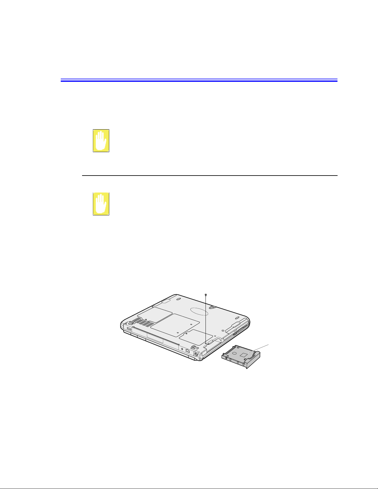
Using the Hard Drive
YourcomputerincludesaremovableIDE(integrateddrive electronics)harddrive. The
IDE hard drive can store the data and programs your computer uses. The drive plugs
into a c onnector on the system board.
Theharddrivethat comeswithyourcomputer hasalreadybeen formatted.Do
not format the hard drive. Doing so destroys all data contained on the drive. If
you need to format a newdrive,orwantto erasealldataonyour existinghard
drive, refer to the manual for your operating system.
Removing the Hard Drive
To prevent loss of data and damage to the disk, do not remove the harddrive
while the computer’s power is on and do not drop or jar the hard drive.
To removethehard drive from the computer:
1. If you are installing a new hard drive, backup the application anddatafileson the
old hard drive before removing it from the computer.
2. Turn the computer’s power off.
3. Close the LCD panel, a nd turn the computer over so that the bottom of the unit
faces up.
4. Remove the screw that holds the hard drive in place.
Bottomof computer
NEED NEW PICTURE
Hard-drive
5. Pull the hard drive out of the computer.
Using the Hard Drive 57
Page 68

Installing a Hard Drive
To install a hard drive:
1. Remove the old hard drive from the computeras describedin the previoussection.
2. Slidethenew drive intothehard drive compartment.Make sure thedriveis pushed
back as far as it will go.
3. Install the screw that holds the hard drive in place.
4. If required install windows and appropriate device drivers according to the
instructions below.
(Re)Installing Windows and Device Drivers
Use System Recovery CD to (re)install OS and System Software C D to (re)install
device' drivers.
The System Recovery CD is used to (re)install the OS and System Software
to a new HDD or recover from a system crash.
Notebook computers that ship from the factory include System Recover CDROM and System Software CD-ROM, which contains a copy of the
applications and drivers needed for computer's operating system.
In the unlikely event that programson the computer hard drive become
corrupted or are erased, youcan use the S ystem Recovery CD-ROM to
reinstallyour operating system and then System Software CD-ROM to
reinstallyour original applications and drivers.
58 Users Manual
Page 69

Video Features and Configuration
Your computer includes a TFT LCD or active-matrix display. The capabilities of the
screen plu s the video drivers installed on the c omputer determine the quality of the
image your LCD can display.
The following sections describe the display capabilities of your computer.
Resolution and Colour Depth
The resolution of the LCD is the sharpness of the image it can display. Resolution is
measured by the number of pixels (individual dots) displayed on the entire screen. In
general, the more pixels the LCD can display, the better the image.
Your LCD screen is XGA. In XGA, the screen has a maximum display of 1024x768,
about 800,000 pixels.
The number of colours the LCD can display is measured by how many bits the LCD
uses to represent each pixel:
16-bit colour can support 64 K (65,536) colours.
•
32-bit colour can support 16 M (16.8 million) colours.
•
All these video modes can bedisplayed on an external monitor. However, if you
disconnect an external monitor that was attached to your computer and then start the
computer, the LCD may revert to a different resolution than the one you chose for the
external monitor.
Video F eatures and Configuration 59
Page 70
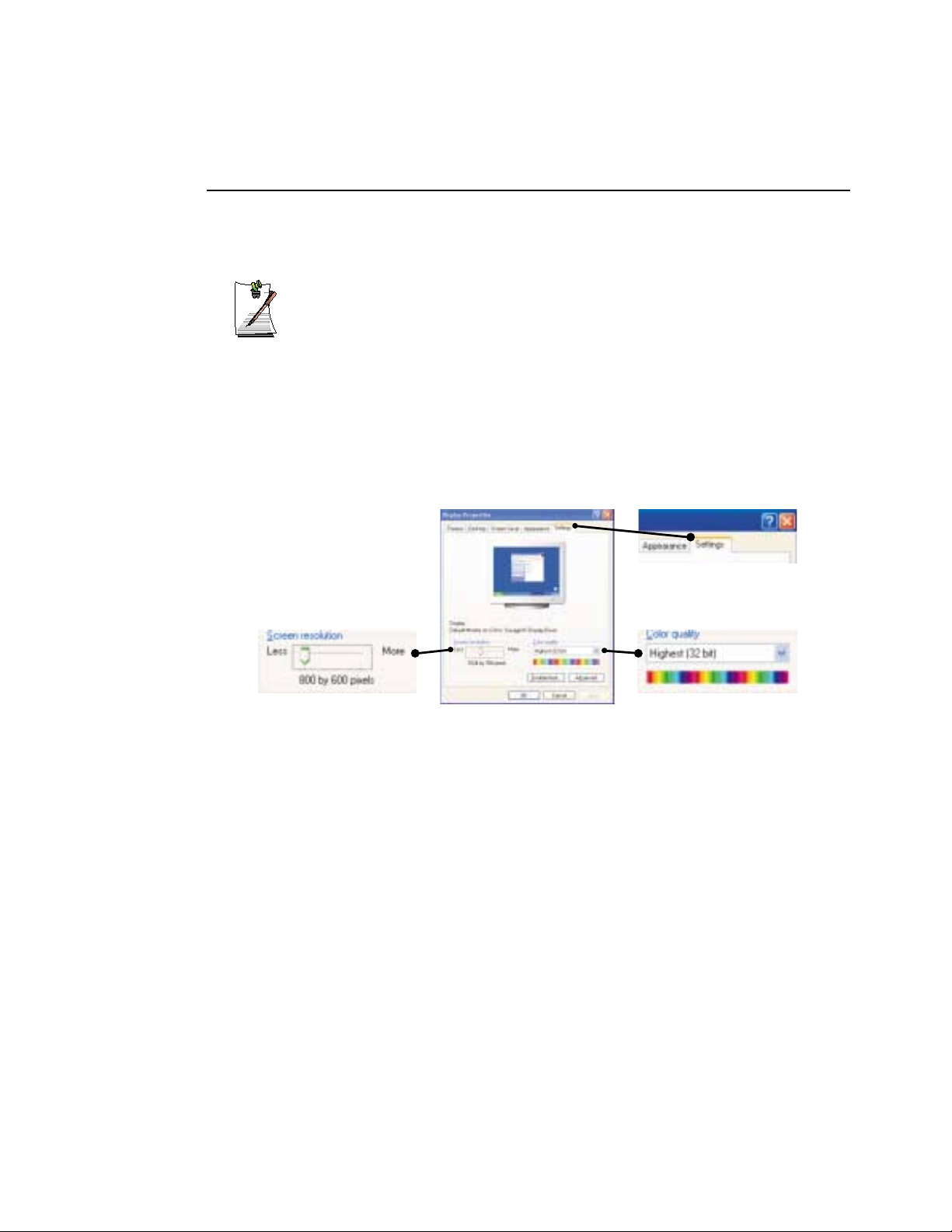
Configuring Display Features
The following sections describe how to configure the display settings on your
computer.
Display Resolution Notes:
WhenWindowsXPi s initiallyinstalled itwillautomaticallyadjustthe resolution
to maximum available.
Changing Colour Depth and Resolution
To change the colour depth a nd resolution of your LCD or external monitor:
1. Click Start > Control Panel > Appearance and Themes.
2. Click the display icon. The Display Properties window appears.
3. Click the Settings tab. The Settings s creen appears.
Display Properties Settings
4. To change the colour depth, click the arrow next to theColour qualitypalette and
5. To change the resolution, click and drag the slider under the Screen resolution
6. Click OK.
7. Follow the prompts that appear on the screen.
60 Users Manual
Resolution Slider
select the available colour depth you want.
until you select the available resolution you want.
Colour Palette
Page 71

Using Dual View Mode
Single View mode is the basic display mode which displayssame view on all the
display devices connected to a system.
Dual View m ode is the “Extended screen mode” s upported in Windows, which
displays separate viewson each display devicesconnected to a system.
The default setting on your system is Single View mode.
Setting Dual View Mode
To set Du al View mode on your system:
1. Connect peripheraldisplay device such a s monitor or TV to your system and start
the system.
2. Select Start > Control Panel > Appearance and Themes.
3. Click icon. The Display Properties window appears.
4. Click the Settings tab. The Settings s creen appears.
5. Check Extend my Windows desktop onto this monitor.
6. You can drag thesecondmonitorimage to position whereyouwantyourextended
screen space with respect to the primary monitor (usually the LCD).
To confirm whether the system is set properly with Dual View mode:
1. Open Display properties and click Settings tab.
2. Place the cursor on the first monitor picture and click and hold over a second, a
number1
the second monitor picture and click and hold over a second, then digit number2
will be shown on the second actual monitor screen.
3. The monitor displays digit number 1 is the primary monitor and number 2 is the
secondary monitor.
InWindowsexplorer,theprogram isdisplayedonthe primarymonitor,ifyou can
drag it to the secondary monitor, then Duo View mode is now working properly.
willbe shown on the firstactualmonitor screen. And place the cursor on
UsingDual View Mode 61
Page 72

The secondarymonitorhas a display of 256 colours (colourdepth) and 640x480 pixels
(resolution)at first.Thec olour depthandresolutionofprimary/secondarymonitorsa re
separately changeable.
To reset the systemto Single View mode:
1. Start Display properties.
2. Click Settings tab.
3. Click the second monitor among two monitor pictures.
4. Uncheck Extend my Windows desktop onto this monitor.
5. Click OK.
62 Users Manual
Page 73

Using the TV -Out Po rt
Using t he TV-out port, a compatible TV or other compatible display device can be
connected and an image displayed.No Audio is transmitted through the TV-Out port.
To check if and how your TV displays the TV-out signal see the documentation
included with your TV.
To enable TV-out:
1. Connect the TV to the TV-Out port using an appropriate cable.
2. Click Start > Control Panel > Appearance and Themes.
3. Click Display > Settings
4. Ensure Extend my Windows desktop onto this monitor box is unchecked.
5. Click Advanced > S3DuoVue.
6. Click the check box to the left of the text “TV”.
7. Follow the screen prompts and the LCD screen display will be duplicated on the
television.
If the TV symbol is grayed out then the system has not detected a TV, check
that the TV standard in the System Setup is set correctly and that the TV is
turnedon and connected properly.You can not use TV-out port in DO S mode.
8. Click Apply or OK.
UsingDual View Mode 63
Page 74

Using Options
You canorderthe followingoptions foryourNotebook computerfromyour authorised
reseller:
An extra AC adapter.
•
An auto adapter that enables you to charge the computer’s battery and operate
•
the computer while in an automobile.
An extra battery pack.
•
An upgraded hard drive. Optional hard drives are available to fit in the hard
•
drive compartment or the Flex-Bay.
32, 64 and 128 MB SDRAM memory modules that enable you to upgrade your
•
computer’s memory to a maximum of 256MB.
A CD-ROM drive module.
•
A DVD-ROM drive module.
•
ASuperdiskLS-120drive.
•
Docking options that enable you to use your computer like a desktop computer.
•
Wireless LAN
•
The options that are available may change periodically. Contact your reseller for
updated information on current and new options.
AC Adapter
The optional AC adapter operates in the same way as the adapter that came with your
computer does. See “Attaching the AC Adapter” on page 9 for information about the
AC adapter.
64 Users Manual
Page 75

Auto Adapter
The autoadaptere nables you to power your computerand charge the computerbattery.
In an automobile, through the +12 volt c igarette lighter socket.
•
To use the adapter:
1. Plug the adapter c able into the AC adapter connector on the computer.
2. Connect the adapter to the cigarette lighter socket.
The light on the adapter is green when the adapter is working properly. The light may
beredforafew secondswhenyoufirstplugin the adapterorwhile youusethe adapter.
This is normal. If the light remains red, check to make sure the adapter is connected
correctly.
If the adapter is plugged in and the adapter light does not turn on:
Check the adapter connections.
•
If you are in an a utomobile, turn on the automobile’s ignition to supply power
•
to the adapter. In some vehicles, power to the cigarette lighter socket is always
on and you do not need to turn on the ignition.
If the previous procedures do not activate the adapter, yo u may need to change
•
the fuse in the adapter. To remove the fuse from the adapter, unscrewthe
adapter cap with a pair of pliers and remove the cap. Replacethe fuse with an 8
amp fuse. In an automobile, you may need to replace the fuse in the cigarette
lighter socket.
When you connect the adapter to the cigarette lighter, the computer’s battery starts
charging immediately.
To preventlossofdata and possible damageto the computer, unplug the auto
adapter when starting and stopping theautomobile engine.
Using Options 65
Page 76

Battery Pack
You can order another smart lithium-ion battery pack or dumb Ni-MH pack for your
computer.See “UsingPowerManagement Options” on page52for informationon the
battery.
Hard Drives
You can orderoptional hard drivesforyoursystem. A hard drive can beinstalled in the
hard-drive compartment to replace your existing hard drive or you can order a hard
drive that fits in the Flex-Bay. See “Installing a Hard Drive” on page 58 for
information on installing a new drive in the hard-drive compartment. See “Using the
Flex-Bay” on page 29 for information on installing a device in the Flex-Bay.
Memory Modules
You can increase system memory by installing optional memory modules. You can
install a 32, 64 or 128 MB modules.
To avoid possible systemproblems, use only approved memory modules in
your computer.
Before You Install Memory
Take the following precautions when installing a memory module:
66 Users Manual
To prevent personal injury and damage to the equipment, follow the
precautions listed here before installing a memory module.
Before you remove the memory module compartment door, turn off the
•
computer, unplugthe power cord, and remove the battery. Also, disconnect any
peripheral devices.
Before handling a memory module, discharge any static electricity by touching
•
a grounded surface or using a grounding wrist strap.
Do not insert objects with conductive material, such as metal screwdrivers or
•
graphitepencils, into the memory-module compartment.
Be careful in handling the metal plate of the memory door.
•
Page 77

Installing a Memory Module
Handle a memory module carefully. Hold them only by the edges.
To installa memory module:
1. Turn the computer over so that the bottom faces up.
2. Using a screwdriver, re move the screw that holds the memory-module
compartment door in place.
3. Grasp the edge of the door and pull the door off the chassis.
4. Remove installed modules if necessary:
Memory Module Precautions:
When r emoving the module, pull on the plastic portion of the connector slots
tabs only. Do notpull on the metal partof the tabs, this may damage the tabs.
Using Options 67
Page 78

a. Pull the tabs on the connector slot outward slightly, until the edge of the
memory module pops up.
Need
Tab
NEW
Picture
Tab
b. Hold the memory module by the edges and pull it forward out of the
compartment.
5. Align the connector on the memory module with the connector of the slot.
6. Pushthememory moduleinto theslotataslightangleuntiltheconnectorsarefully
engaged.
7. Push down on the edge of the memory module until the module snaps into place.
8. Align the memory module compartment door with the compartmentand push the
9. Reinstall the screw you removed in step 2.
10. Turn on the computer and perform a complete POST to check the memory
CD-ROM Drive
If your systemdidnot ship withaCD-ROM driveincluded, you can order a drive. See
“Using the C D/DVD-ROM Drive” on page 33 for directions on installing the CDROM drive.
68 Users Manual
door down until it snaps into place.
integrity.
Page 79

DVD-ROM D rive Module
If your system did not ship with a DVD-ROM drive included, you can order a drive.
The DVD-ROMdrivemodule canbeinserted intoyour computerexactly asyouwould
insert a CD-ROM. See “Using the CD/DVD-ROM Drive” on page 33 for directions
on installing and using the CD-ROM drive. There is DVD software included with the
drive that will enable you to play DVD movies from the DVD-ROM drive.
Superdisk LS-120 Drive
The LS-120 drive enables you to store 120 MB of data on a single, 3.5-inch LS-120
diskette. It is backward compatible with standard HD 1.44MB 3.5-inch diskettesandit
canreadandwritetothemuptothreetimesfaster.TheLS-120drivefitsintheFlexBay, see “Using the Flex-Bay” on page 29
If you want to boot from LS-120, you have to disable "Diskette A:" in BIOS
setup Boot menu.
Docking Options
Contact your reseller for a list of docking options available for your Notebook
computer. User’s manuals are included with the docking options.
Wireless LAN
This option will allow wireless connection to a network in work as well as home
environments. To setup and use the WirelessLAN, please refer to the user manual
provided at the time of purchase.
Using Options 69
Page 80

Troubleshooting
If you ever have difficulty running your computer, follow these steps:
1. Consult the following sections for adviceon how to handle system problems.
2. Refer to warnings, cautions and notes within applicable portion of this manual.
3. Refer to “Windows” and other “Program” manuals as applicable.
4. If steps 1 to 3 do not resolve the problem, contact the Samsung Helpline.
Operating Problems
This section answers most of the frequently asked questions associated with simple
problems you may encounter while using yourcomputer. This covers the most
common problems and give the best solution to that problem. However, if you
experience a problem not discussed here, please contact the Samsung Helpline.
Problem Action
The computer does nothing
whenyouturniton.
Some of the letter keys type
numbers instead of the
indicated letters.
Battery power seems to run
out faster than expected.
Certain software programs
“hang” during operations
when there is no interaction
with the keyboard or
peripheral devices.
PC Card does not work
correctly.
Has the battery run down? Connect the power cord to the
computer and recharge the battery. Try turning on the
computer again.
Is the Num Lock light on? If so, the numeric keypad
on the keyboard is active. To return the keypad keys
to typing letters, press <Num Lock>.
If you are running the computer from the battery rather
than thepower cord, make sure that youset the IdleMode
field in System Setup to On. This setting enables the
microprocessor and thehard drivetoslow down whenthe
computer is not busy.
Your computermay be in Suspend or Rest mode. Tap the
touchpad to resume from Suspend or press the power
button to resume from rest.
Makesurethatthe PC Card is insertedleft side up in
thePCCard slot.Check thatthe cardisinsertedfully
into the slot. If you are using a PC Card modem,
check the modem cable connections.
70 Users Manual
Page 81

Problem Action
Your ATA or Compact
Flashcard do not work.
The System Setup settings
are not retained when you
turn off the computer.
No sound.
System/BIOS behaves
erratically
A patch is provided for these cards on the Recovery CD
The CMOS battery inside the computer may need to be
replaced. The CMOS battery provides power to save the
systemBIOSinformationwhent he computeristurnedoff.
Normally,the CMOS battery lasts for several years.Do
not attempt to open the chassis and replace this battery
yourself or your warranty is void. Have an authorized the
manufacturer’s service center replace the CMOS battery.
Verify if the mute check box is checked or the volume is
not turned down in the pop up menu by clicking the
speaker icon of the task bar.
If you caused an abnormal power interruption (i.e..
removingbattery whileonbatterypower),youmay cause
BIOS data corruption.
Troubleshooting 71
Page 82

Video Problems
Problem Action
Nothingappears on the LCD
panelwhenyouturnonthe
computer.
Error Message when
enteringPowerManagement
while in Multimonitor mode.
Nothing appears on the
externalmonitorwhen you
switch the display to it.
OnlytheLCD Displayworks
when system returns from
Power m anagement mode
while in Multimonitor mode.
The external monitor
displaysflashes or waves.
Adjust the brightnesson a TFT LCD. Are you using
an external monitor? If so, press <Fn+F5> to return
to the LCD panel.
If the secondary monitor is set to 256 colours, this error
messagecouldappear.Change thecolourofthe secondary
monitor to ‘high colour (16 bit)’.
Is the monitor properly connected to the c omputer?
Is themonitor’s powercord connectedto an AC wall
outlet?Check thebrightnessandcontrastcontrols on
the monitor. Doe s the program appear on the LCD
panel instead of the external monitor? If so, press
<Fn+F5> to switch to the monitor. Try turning the
monitor off and on again.
The system resets to the original BIOS setup when the
system returns from the power management mode. If the
Display mode, in the Advanced menu of BIOS setup is set
to LCD, then only the LCD will be turned on when the
system wakes up.Set the Display mode in the BIOS to
Both to turn on the LCD & CRT on wakeup.
Check the cables between the monitor and the computer.
Are they properlyinstalled?
72 Users Manual
Cannot toggle between CRT
and LCD while playing the
3D game.
There is LCD or CRT h as
noise (speckles, lines or
ragededges)onthe
picture w hen pl aying a
MPEGfilewiththeMedia
player/ DV D software or
using the USB camera.
In DOS mode the CRT/LCD
button does not work.
If you are using the Multimonitor mode, you can not use
the <Fn+F5> key combination and also you cannot use
this function in 3D games using Direct-X.
Adjust the resolution and the colour to 1024 x 768 and 16
bit to display clearly, or avoid playing two programs at the
same time.
The LCD only mode is not supported using this Key
combination.
Page 83

Problem Action
If the connected CRT
monitordisplay isnot steady.
If the refresh rate is not optimal for the connected CRT,
then this problem may occur.
To correct this problem do the following:
1.Click Start > Settings > Control Panel.
2.Double Click the Display icon to open the Display
properties.
3.Select Settings
4.Click the Advanced button.
5.Click the Adapter tab
6.AdjusttheRe fresh ratetooptimal orotherselections
until you see the CRT clearly.
Troubleshooting 73
Page 84

Modem Problems
Problem Action
My modem doesn't connect
to servicesordisconnects
during communication
When using a PBX phone
system I can't dial on my
modem.
Screen displays random or
garbage characters during
communications.
If your modem has difficulty in connecting to on-line
services and sustaining communications, first check if
other devices are connected and remove them. Also
remove any extension leads.Interference from certain
devices or poor line power conditions may degrade the
quality of your connection. Under these conditions
gradually reduce the communication speed of your
modem until a reliable connection is achieved.
Check with your on-line service provider.
IfyouuseaPBXphonesystemyoumayneedtopressa
number i.e. '9' to connect to an external line, you should
enterthe followingcommandbeforetrying theconnection
and check modem initialization. (ATX3&W)
And add “9,” as the external line prefix (example) of the
phone number when using the dial command
“ATDT9, 123-4567”.
After your modem has connected to the on-line service,
your screen may display garbage characters or afterimages in screen transitions. This problem is caused by a
mismatch ofthe terminalmodesbetweencommunications
service andcommunicationsprograms.You need tomatch
the terminal modes to eachother. Refertothe user's guide
of the communications program you're using.
74 Users Manual
Reports error message that
insufficient Hard Disk space
is available.
FAX Problems:
Depending on telephone line status, or types of Fax machines/programs that
send/receive the Fax, Fax transmission/reception may not work correctly. In
that case, please try other Fax programs. (e.g. W in Fax)
Delete the unnecessarymessages or data you received by
Modem or Fax every one to three months as required.
Ifyou'reusing theinternet,many pictureand datafilescan
get downloaded to yourHARD DISK every timeyou visit
a ho me page, wh ich will consume a lot of your HARD
DISKspace. Delete the unnecessarymessages or data you
received b y Modem or Fax every one to three months as
required. For moredetailedinformation about themethod
of deleting, refer to the help of the W eb browser you've
been using or your user's guide.
Page 85

Windows & Device Drivers
If for some reason your system crashes you may corrupt your HDD, Windows
Operating system and/or some of your device drivers. If this is the c ase, use System
Recovery CD to reinstall OS and System Software CD to reinstall the corrupt device
drivers.
System Recovery CD:
The System Recovery CD WILL erase ALL of your data and programs
currently installed on your computer.
TheSystemRecoveryCD isusedtoreinstalltheOSand the System Software
CD for a new HDD or to recover from a system crash.
Windows Driver (Re)Installation
Simply install the driver(s) according to th e instructions b elow :
1. Insert the System Software CD-ROM.
2. Follow the directions provided in the opening window.
Samsungmay, from time to time, issue updated drivers. These are posted on
the Samsung Support website at www.samsungpc.com
When updating drivers, please select the “Supported” driver with the
revision number.
Troubleshooting 75
highest
Page 86

Specifications
Dimension
* LCD viewing area
LCD viewing area (14.1 TFT) 285.7 x 214.3 mm
LCD viewing area (15” TFT) 304.8 x 228.6 mm
* All-In-One type computer
Width 31.65 cm
Depth 26 cm
Height 38.4 cm
Weight (with integrated floppy drive,
Li-Ion battery & 14.1” TFT LCD & weight saver)
Environment
Ambient temperature, operating 10o–32oC
Ambient temperature, storage -5o–40oC
Relative humidity (noncondensing), operating 20–80%
Relative humidity (noncondensing), storage 5–90%
Altitude, operating 0to2,348m
Altitude, storage 0 to 12,192 m
Shock, operating 10 G for 11 ms half sine
Shock, nonoperating 60 G for 11 ms half sine
3200 g
Lithium-Ion Smart Battery
NormalWeight 450g
Nominal open circuit voltage 11.1 VDC
Capacity, typical 6000 mAhr, 66.6whr
Charging time, approximate, with computer turned off , typical 3.0 hr
Charging time, approximate, with computer turned on , typical 5.0 hr
Average battery life,with no power management enabled 3.0 hr
External AC Adapter
Operating voltage 100-240 VAC
Line frequency 50-60 Hz
Input current 1.5 A 100 V ~ 0.8 A 240 V
Output current 3.15 A
Output voltage 19.0 VDC
76 Users Manual
Page 87

Abbreviations
A ......... Amperes
AC . . . . . . . . Alternating current
ACPI . . . . . . Advanced Configuration and P ower management Interface
APM . . . . . . Advanced Power Management
ATA. . . . . . . AT attachment (refers to the hard-drive interface in an AT-
ATAPI . . . . . AT attachment packet interface
BBS .......Bulletinboardsystem
BIOS . . . . . . Basic input/output system
C ......... Centigrade
CD ........Compactdisc
CD-ROM . . Compact disc read-only memory
cm ........Centimeters
COM . . . . . . Communication (as in communication port)
CMOS. . . . . Complementary metal-oxide semiconductor
compatible computer)
DC . . . . . . . . Direct current
DMA ......Directmemoryaccess
DPMS . . . . . Display power-management signaling
DRAM. . . . . Dynamic random access memory
DSTN . . . . . Double layer super twist ne matic
ECP . . . . . . . Extended capabilities port
EPP . . . . . . . Enhanced parallel port
g..........gram
G ......... Gravity
GB . . . . . . . . Gigabytes
hr.........hour
Hz ........Hertz
IDE . . . . . . . Integrated drive electronics
I/O . . . . . . . . Input/output
IRQ . . . . . . . Interrupt request line
Abbreviations 77
Page 88

ISA . . . . . . . Industry Standard Architecture
KB ........Kilobytes
kg.........Kilograms
LAN. . . . . . . Local-area n etwork
lb..........Pounds
LBA. . . . . . . Logical block addressing
LCD. . . . . . . Liquid-crystal display
m .........Meters
mA........Milliampere
mAhr......Milliamperehour
MB. . . . . . . . Megabyte
mm . . . . . . . millimeter
MPEG. . . . . Motion Picture Experts Group
MPU . . . . . . Microprocessor unit
ms ........Millisecond
PDF . . . . . . . Portable document format
PC . . . . . . . . Personal computer
PCI . . . . . . . Peripheral component interconnect
PCMCIA. . . Personal Computer Memory Card International Association
POST. . . . . . Power-on self-test
PNP .......Plugandplay
PS/2 .......PersonalSystem/2
RAM ......Random-accessmemory
ROM . . . . . . Read-only memory
SVGA . . . . . Super video graphics array
TFT . . . . . . . Thin-film transistor
USB . . . . . . . Universal serial bus
V ......... Volt
VAC . . . . . . Voltage alternating current
VCC . . . . . . Voltage collector current
VDC . . . . . . Voltage direct current
whr .......Watthour
78 Users Manual
Page 89

Glossary
AC adapter
The AC (or alternating current) adapter regulates current coming into your
computerfrom thewall outlet. The current at the wall outlet is alternating current
and needs to be changed by the adapter to DC (direct current) before your
computer can use it for power.
ACPI
ACPI (Advanced Configuration and Power Interface)- a method for describing
hardware interfaces in terms abstract enough to allow flexible and innovative
hardwareimplementations and concreteenoughto allowshrink-wrap OS code to
use such hardware interfaces.
BIOS
BIOS standsfor basic input/output system. The BIOS is software (often called
firmware)that is independentofany operatingsystem. It enablesthecomputerto
communicate with the screen, keyboard, and other peripheral devices without
using programs on the hard disk.
TheBIOSonyourcomputer isflashBIOS,which meansthatithasbeen recorded
on a flash memory chip that can be updated if needed.
Boot
To start your computer. A cold boot resets the entire computer and runs through
all computer self-tests. A warm boot clears out computer memory only.
Boot disk
A disk containing operating system programs required to start your computer. A
boot disk can be a floppy disk, hard drive, or compact disc.
Byte
Thebasic unit of measure for computer memory. A character—suchas a letter of
the alphabet—uses one byte of memory. Computer memory is often m easured in
kilobytes (1,024 bytes) or megabytes (1,048,576 bytes).
Each byteis made up of eight bits. For more information on bytes and bits, see an
introductory book on computers.
Cachememory
Cache is very fast, zero-wait-state memory located between the microprocessor
and main memory.Cachereduces the average time required by the
microprocessor to get the data it needs from the main memory by storing recently
accessed data in the cache.
Glossary 79
Page 90

CardBus
CardBus technology enables the computer to use 32-bit P C Cards. Hardware in
the computerand the Windows operating system provide support for the 32-bit
cards. The voltage of 32-bit cards (3.3 volts) is lower than that of 16-bit cards (5
volts). The 32-bitcards cantransmitmore data at atimethan the 16-bitcards,thus
increasing their speed.
CMOS memory
CMOS (complementary metal oxide semiconductor) memory is powered by the
CMOSbattery. The SystemSetupsettingsandother parametersaremaintainedin
CMOS memory. Even when you turn your computer off, the information in
CMOS memory is saved.
COM port
COM standsforcommunication.COMportsarethe serialportsin your computer.
Compact Disc
A compact disc (CD).
Conventional memory
Thefirst 640KBofsystemmemory.Operating systemsand application programs
can directly a ccess this memory without using memory-management software.
Disk
The device used by the computer to store and retrieve information. Disk canrefer
to a floppy disk, hard disk, or RAM disk.
80 Users Manual
Disk cache
A software devicethat accumulatescopies of recently used disksectorsin RAM.
The application program can then read these copies without accessing the disk.
This, in turn, speeds up the performance of the application.
A cache is a bufferfortransferring disk sectorsinandout of RAM. Data stored in
a disk cache is a copy of data already stored on the physical disk.
DMA (direct memory access)
A method of transferringdatafrom a device t o memory without having the data
pass through the m icroprocessor. Using D MA can speed up system performance.
DPMS
Display Power Management Signalling. Displays or monitors that comply with
this can be managed by the Power Management features found in the system
setup.
Floppy disk
A removable disk, also called floppy or diskette.
Page 91

Harddrive
Also called fixed disk. A hard drive is connected to the computer and can be
installed or removed. Data written to a hard drive remains until it is overwritten
or corrupted.
The 2.5-inch hard drive in your computer was designed for use in a notebook
computer. Because hard drives in notebook computers are smaller than those in
desktop computers,their maximum storage capacity may be less than that of
desktop hard drives. However, because of their smaller size, the drives handle
shock and vibration better than larger drives, which is important for a notebook
computer.
I/O
Input/output. R efers to peripheral devices, such as printers, that are addressed
throughanI/Oaddress.
I/O address
I/O stands for input/output. Peripheral devices, such as printers, are addressed
through the I/O port address.
IRQ (interrupt request line)
The IRQ is a hardware line that a device uses to signal the microprocessor when
thedeviceneeds the microprocessor’sservices.ThenumberofIRQs is limited by
industry standards.
LCD (liquid-crystal display)
The LCD screen on your computer differs from the display screen of a desktop
monitor. Most desktop monitors use CRT (cathode-ray tube) displays, which
workbymovinganelectron beam acrossphosphordots on the back of the screen.
The phosphordotslightup to show the image. LCDs use a liquid-crystalsolution
between two sheets of polarizing m aterial. Electric current passing through the
liquidaligns thecrystals sothatlightcan or cannotpassthroughthem, creatingan
image.
MB (megabyte)
1,024 kilobytes.
Megabit
1,048,576 bits or about 128 kilobytes.
Operating system
A program that supervises the computer's operation, including handling I/O.
Application programs and users can request operating-system services. A user
might request operation-system services to copy files or format a disk. An
application program might use the operating system to obtain keyboard input,
write data to a file, or write data to a screen.
Glossary 81
Page 92

PC Card
PC Card stands for personal computer card. T he Personal Computer Memory
Card InternationalAssociation (PCMCIA) defines the s tandards used to develop
all PC Cards. PC C ard types include: modems, Ethernet adapters, SCSI adapters,
ATA cards, and memory cards.
PC slot
The PC slot is the hardware slot in the computer where the PC Card is placed.
Pixel
A pixel is an individual dot in a graphic displayed on your computer. The pixels
areso close togetherthat they look as though they are connected. An LCD screen
displays thousands or millions of pixels.
Plug and Play
Aplugandplayoperatingsystemautomaticallyconfigurescomputer components
to work with your system. With this type of operating system, you normally do
not need to set jumpers on devices or set memory addresses or IRQs.
RAM (random access memory)
The computer's systemmemory, including conventional and extended me mory .
You can write to and read from RAM. Information stored in RAM is temporary,
andiserasedwhenthesystemisturnedoff.
Refresh r ate
The refresh rate is the rate at which the image on the LCD screen i s rewritten to
the screen. A fast refresh rate helps keep the image from flickering.
82 Users Manual
Resolution
The resolution is the sharpness or clarity of the image on your LCD screen.
Resolution is measured by the number of pixels the computer’s screen can
display.For example,a resolutionof800 x 600 means that the screen can display
800pixels inrowandcan display600 rows. Themorepixels displayed,the higher
the resolution and the better the image.
ROM (read-only memory)
Permanent computer memory dedicated to a particular function. For example, the
instructions for s tarting the computer whe n you first turn on power are contained
in ROM. You c annot write to ROM. (ROM is not the same as RAM).
Sector
Also known as disk sector. The portion of a track that is numbered and can hold
a specified number of characters (usually 512 KB).
Page 93

Shadow RAM
Awrite-protecteda rea of RAM thatcontainsacopyofthe BIOS. Asthecomputer
boots, the BIOS is copied from its permanent location in ROM to RA M. The
BIOS can be executed much faster in RAM than in ROM. The BIOS remains in
shadow RAM until you turn off the computer.
TFT (thin film transistor) LCD
A TFT LCD uses a separate transistor circuit to control each pixel. This
technology providesthe best resolution for an LCD screen. A TFT LCD is also
sometimes called an active matrix LCD.
Zoomed video
Zoomed video technology enables zoom video PC Card to transfer data directly
from the c ard to video and audio systems without going through the
microprocessor. This processimproves video performance. Video conferencing
and real-timemultimedia devices, such as video cameras, are supported by zoom
video.
Glossary 83
 Loading...