

Page 1

Global LCD Panel Exchange Center
www.panelook.com
One step solution for LCD / PDP / OLED panel application: Datasheet, inventory and accessory!
www.panelook.com
Page 2

Global LCD Panel Exchange Center
FOR MESSRS: DATE: .Mar 26
CUSTOMER
CUSTOMER’S SPECIFICATION
www.panelook.com
(42”SD V3.1 )
th
.2004
107cm (42 Inch) Wide Plasma Display Module
MODEL : S42SD-YB03
(NTSC/PAL)
* This specification will be approved by both
* Please return one of this specification with your signature for approval.
Proposed by: Approved by:
Signature
Signature .
CUSTOMER and Samsung SDI Co.,Ltd.
General Manager. Yeonyong Choo
Quality Innovation Team,
PDP ) Division,
Module Version : 42”SD(V3) TCP CONFIDENTIAL Spec. Rev. : Version 6
One step solution for LCD / PDP / OLED panel application: Datasheet, inventory and accessory!
www.panelook.com
Page 3

Global LCD Panel Exchange Center
Samsung SDI Co. Ltd. Specification Plasma Display Module
Revision Date Description Of Changes Approval
www.panelook.com
Revision History
1
2
3
4
5
AUGUST. 09.
2003
OCT. 16.
2003
Nov. 12
th
2003
Feb. 18
2004
Feb. 23
2004
Newly established
Non-supply items(38p)
- Display Performance(7p)
- Gamma Chracteristic(14p)
- Power spec Update(25-26p)
- Absolute MaximumRatings(16p)
Samsung SDI Confidential -2 / 2- Spec rev.: V6, Mar/26/2004
One step solution for LCD / PDP / OLED panel application: Datasheet, inventory and accessory!
www.panelook.com
Page 4

Global LCD Panel Exchange Center
Samsung SDI Co. Ltd. Specification Plasma Display Module
TABLE OF CONTENTS
1. DESCRIPTION ……………..…..…………………………..…………………….….. .5
2. FEATURES ………..………………………………………..……………………..…..5
3. PRODUCT NAME AND MODEL NUMBER …………………………………….….5
4. FUNCTION OUTLINE …………….………….……………………………..…………5
5. BLOCK DIAGRAM ………………………………….………………………..……….6
6. DISPLAY CHARACTERISTICS …………….…………………………………….….7
6.1 Display Performance ……………………….…………………………………..………………….…..……7
6.2 Display Cell Arrangement ……………….…………………………………………………..………….…8
6.3 Brightness Measurement Condition …….…………………………………………………..………..…....9
6.4 Contrast Measurement Condition ……….………………………………………………….……..……...10
6.5 Display Cell Defect Specification ……..……………………………………………..…………………..11
6.6 Brightness Variation Specification ………………………………………………………...…………….…12
6.7 Power Consumption………………..……………………………………..……..……………………...13
6.8 Gamma Characteristics ………………………….……………………..……..…………………..…….….14
www.panelook.com
7. SOUND PRESSURE LEVEL SPECIFICATION ………………..…………………14
7.1 Measurement Condition ………….…….…………………….……………..……..………….………..14
7.2 Sound Pressure Level ………………….……………….…………….………..….……..………….………14
8. MECHANICAL CHARACTERISTICS ……………..………….….………………..15
8.1 Mechanical Specification…………………………………………………………………..………….………..15
8.2 Mechanical Characteristics…………..……………………………………………………..…………..……..15
9. ENVIRONMENTAL CONDITION ………………………………………………..…16
9.1 Recomended Environment Condition ………………………………………………………….………..……16
9.2 Absoluted Environment Condition…………………………………………………………………………….16
10. INTERFACE SIGNAL SPECIFICATION ……..…………………………….…….17
10.1 Configuration Context …………………….………………………………………………………………....17
10.2 Interface function Specifications ……………………….……………………………………………….……18
10.3 Input Signal Definition ……………………………….………………….…………………………….……18
10.4 LVDS Signal Definition and Function ………………..………………………………………………….……18
10.5 Video Signal Definition and Function……………………….………………………………………….……19
10.6 Electrical Condition of Interface Signals ………….…………………………………………………….……20
10.7 Video Signal Interface Timing Conditions ……….………………………………………………….…21~22
10.8 LVDS Interface Timing Conditions ………..……….………………………………………………….……23
10.9 LVDS Connection Specifications…………………….…………….…………………………………….……23
10.10 Connector Specifications ……………………………….……………………………………………………24
Samsung SDI Confidential -3 / 3- Spec rev.: V6, Mar/26/2004
One step solution for LCD / PDP / OLED panel application: Datasheet, inventory and accessory!
www.panelook.com
Page 5

Global LCD Panel Exchange Center
Samsung SDI Co. Ltd. Specification Plasma Display Module
11. SMPS SPECIFICATION ……………………..………………………………….…25
11.1 Connector Location …….……………..……………….…..…………………………...…………….………...25
11.2 Detail Power Specification of SMPS ….…………………..………….…..………….…………………..…26
11.3 Pin Assignment of connectors for Power Supply ………………………………….…………………..……….26
11.4 Power Applying Sequence ………………………….…….…………….……………..…………..….……..27
12. OTHERS ………………………………………………………………………….…28
12.1 Mechanical Dimensions Drawing ………………………………………………….………………….……...28
12.2 Label ………….………………………………………………………….………….…….………………… .29
12.3 Serial No ……….……..………………………………………………………….………………………...29
13. PACKING ………………………………………………………………...…….………30
13.1 Packing Dimension and Parts List …..………………………………………………………………………30
13.2 Packing Assay drawing …..…………………………………………………………………………………. 30
14. RELIABILITY ………………………...………………………………………….…31
www.panelook.com
14.1 MTBF ………..……………………………..…………….………………………………….…..……………31
14.2 Expected Service Life ……….……………….…………………………….……………………..…………31
14.3 Disclaimer ………………………………………………………………………………………………….31
15. WARNINGS/ CAUTIONS / NOTICE……………………………………………….32
15.1 Warnings ….……….……………………………………………………………………….…..…………32 ~ 33
15.2 Cautions ………...……………………………………………….……………………………….….…………34
15.3 Notice ………….……………………………………………………………………………..………..35 ~ 38
16. APPENDIX ……………………………………………….… ..……………………....39
16.1 Module stand supply specification……………………………………………………….…..…………39
Samsung SDI Confidential -4 / 4- Spec rev.: V6, Mar/26/2004
One step solution for LCD / PDP / OLED panel application: Datasheet, inventory and accessory!
www.panelook.com
Page 6

Global LCD Panel Exchange Center
Samsung SDI Co. Ltd. Specification Plasma Display Module
1. DESCRIPTION
The S42SD-YB03 is a 42-inch wide full color plasma display module with a resolution
of 852(H) 480(V) pixels. The display module includes Display Panel, Panel driving
electronics, Logic controller and Power supply .
2. FEATURES
• Wide aspect ratio(16:9) 42 inch diagonal display screen. The display area is 932.94
wide and 532.80 high.
• Slim and light weight. The display module is 66.1 in depth and weights only 20.0
include power supply.
• 16.77 million colors by combination of 8 bits R,G and B digital data
• High brightness, High contrast, Wide viewing angle. The screen has a white
peak brightness of
and a viewing angle of greater than 160 comparable to that achievied with CRTs.
www.panelook.com
.Typical 1000cd/(NTSC), contrast of Typical. 3000:1
3. PRODUCT NAME AND MODEL NUMBER
• Product name : 42-inch Full Color Plasma Display Module3
(Abbreviation : PDP Module3)
• Model number : S42SD-YB03
4. FUNCTION OUTLINE
• The plasma display module has APC(Automatic Power Control) function which
restrict power consumption within certain value with regard to each display load ratio.
• The plasma display module is operated by following digital video signals;
Vertical synchronous signal, Horizental synchronous signal, Enable signal and 8bits
data signal of each R,G, and B color. All signals are based on LVDS level.
• The plasma display module is operated at 50HZ or 60Hz frame rate. It is required
external frame rate conversion in order to display the other formats.
• The plasma display module requires several types of input voltage; voltage for driving
logic board , FET in driving board, sustain, address, reset, scan and x-bias.
• The plasma display module is operated at progressive signal only.
It is required external progressive scan conversion in order to display the other
formats.
• The plasma display module requires 100~240V, 50/60Hz of input power voltage
Samsung SDI Confidential -5 / 5- Spec rev.: V6, Mar/26/2004
One step solution for LCD / PDP / OLED panel application: Datasheet, inventory and accessory!
www.panelook.com
Page 7

Global LCD Panel Exchange Center
Samsung SDI Co. Ltd. Specification Plasma Display Module
5. BLOCK DIAGRAM
LOGIC CONTROL
DATA_R
8Bits
DATA_G
8Bits
DATA_B
8Bits
DCLK
Vsync
Hsync
Enable
LVDS
Interface
Input Data Proc ess or
Data Controller
www.panelook.com
Display
DRAM
Timing Controller
Data
Driver
Timing
Driver
Scan
Timing
DRIVER CIRCUIT & PANEL
Driver
Row
852480 Pixels
Generator
YPulse
8523480 Cells
Column Driver
Generator
XPulse
D3V3
-D 3 V 3 : Voltage for driving logic
-Vcc : Voltage for driving FET
-Va : Voltage for driving address
-Vs : Voltage for driving sustain
-Vscan : Voltage for driving scan
-Ve : Voltage for driving X-bias
-Vset : Voltage for driving reset
Vcc
Vset Vscan
Reference
Figure-1. Block Diagram of Plasma Display Module3
VsVa
Ve
Samsung SDI Confidential -6 / 6- Spec rev.: V6, Mar/26/2004
One step solution for LCD / PDP / OLED panel application: Datasheet, inventory and accessory!
www.panelook.com
Page 8
Global LCD Panel Exchange Center
Samsung SDI Co. Ltd. Specification Plasma Display Module
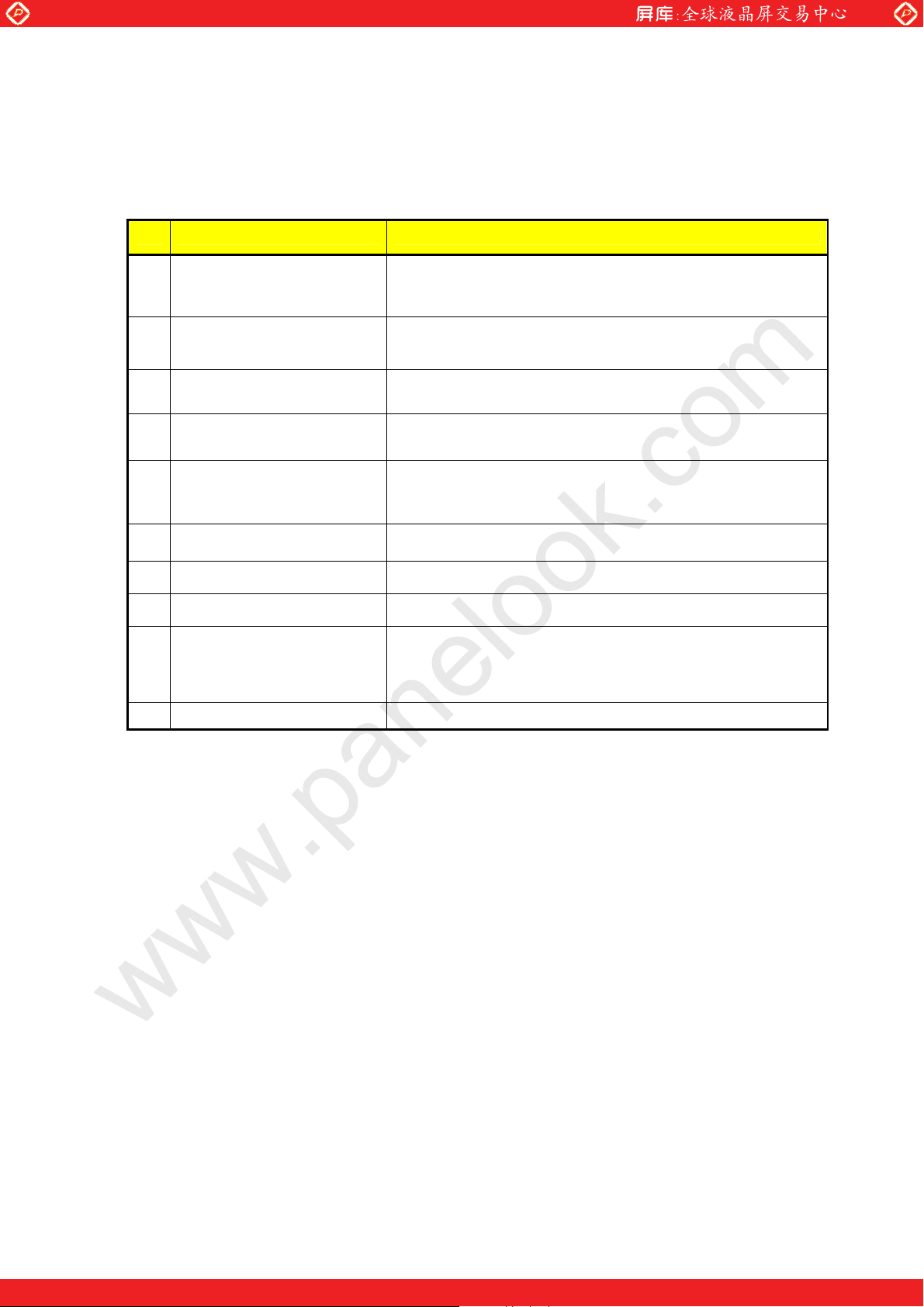
6. DISPLAY CHARACTERISTICS
6.1 Display Performance
No Item Rating
www.panelook.com
1
Display Pixels
2
Display Cells
3
Pixel Pitch
4
Cell Arrangement R,G,B Matrix (refer to Figure-2)
5
Effective Display Size
6
Number of Color 16.77 million colors
7
Peak Brightness *1
8
Contrast Ratio *2 Typical 3000 : 1
Chromaticity Coordinates
9
(Typical Value)
108
Viewing Angle *3
Horizontal 852 Vertical 480 pixels
(1 pixel = 1 R,G,B cells)
Horizontal 2,556 Vertical 480 cells
Horizontal 1.095 Vertical 1.110
Horizontal 932.940 Vertical 532.800
[ 36.73 inch 20.98 inch ]
Typical 1000 cd/(NTSC)
White (100IRE) : X = 0.2850.02 Y = 0.2900.02
Over 160
[Note]
* 1. Brightness and Color Coordinates are the value that measured with 1% load ratio
white pattern . This Signal(LVDS) is supplied from Pattern Generator(VG-828).
The condition for measurement is shown in Figure-3.
* 2. Contrast Ratio is calculated from the display brightness and the non-display
brightness value, and display condition is shown in Figure-3.
* 3 .Viewing angle is the critical angle at which the brightness is reduced to 50% to the
brightness perpendicular to the PDP unit.
Samsung SDI Confidential -7 / 7- Spec rev.: V6, Mar/26/2004
One step solution for LCD / PDP / OLED panel application: Datasheet, inventory and accessory!
www.panelook.com
Page 9

Global LCD Panel Exchange Center
Samsung SDI Co. Ltd. Specification Plasma Display Module
6.2 Display Cell Arrangement
www.panelook.com
1st
Pixel
Row
2nd
Pixel
Row
479th
Pixel
Row
1st
Pixel
Column
Pixel Pitch (Width): 1.095 mm
Pixel
Pitch
2nd
Pixel
Column
RGB RGB RGB
RGB RGB RGB
RGB RGB RGB
3rd
Pixel
Column
Cell
Pitch Heigh t
1.110 mm
850th
Pixel
Column
RGB RGB RGB
RGB RGB RGB
RGB RGB RGB
851st
Pixel
Column
852nd
Pixel
Column
480th
Pixel
Row
RGB RGB RGB
Figure-2. DisplayCell Arrangement
RGB RGB RGB
Samsung SDI Confidential -8 / 8- Spec rev.: V6, Mar/26/2004
One step solution for LCD / PDP / OLED panel application: Datasheet, inventory and accessory!
www.panelook.com
Page 10
Global LCD Panel Exchange Center
g
Samsung SDI Co. Ltd. Specification Plasma Display Module
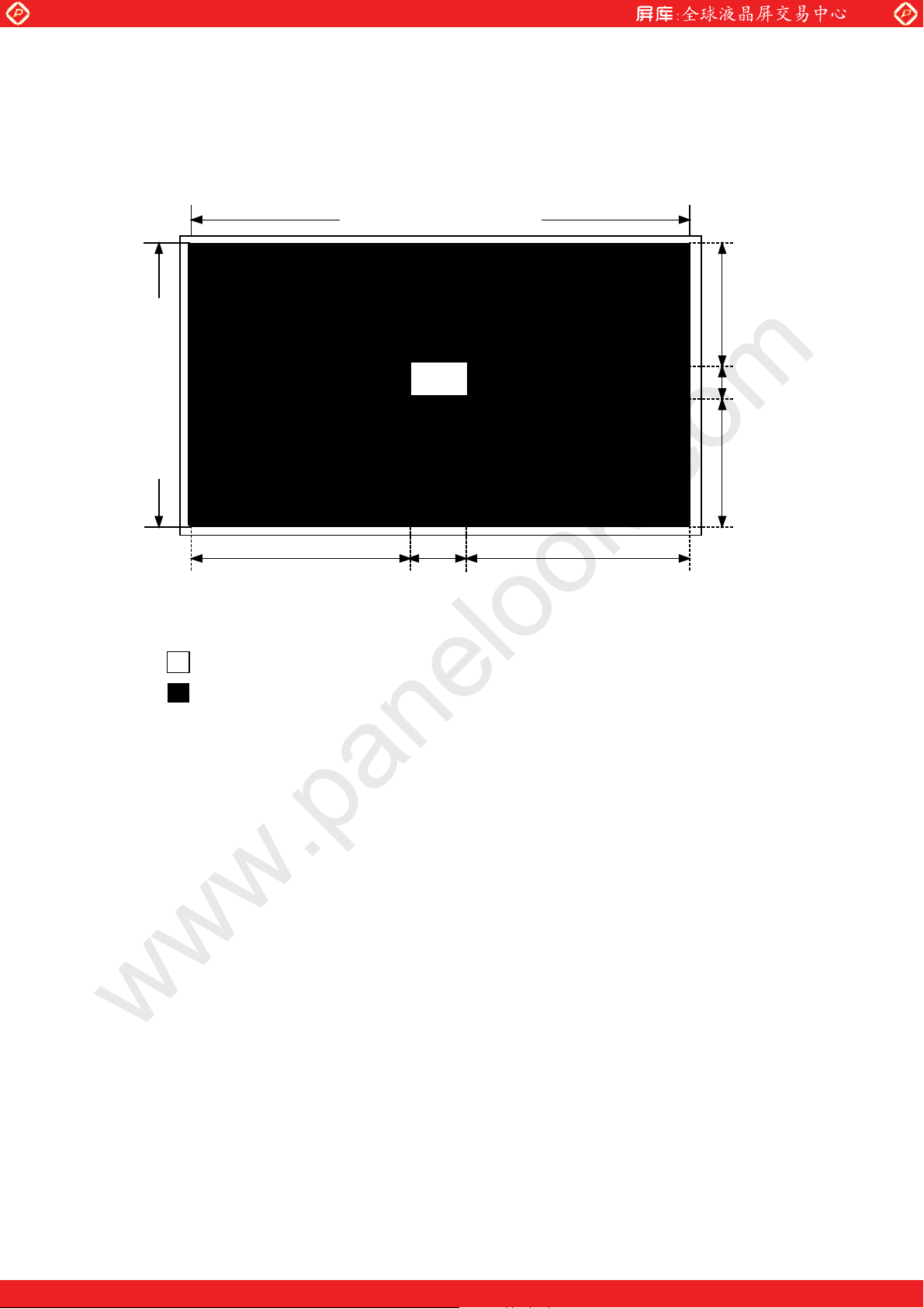
6.3 Brightness Measurement Condition
(1) Display Pattern
www.panelook.com
Effective Display Area
Effective Display Area
383 86 383
marked area : White display area by maximum gradation setting
marked area : Black color (non-display area)
Fi
ure-3. DisplayPattern for Brightness & Contrast Ratio Measurement
(2) Display Area ratio : 1% white window
(3) Vsync : 16.7msec or 20msec
(4) Measuring equipment : MINOLTA CA-100+H
(5) Ambient Temperature : Room Temperature
(6) Ambient Light : dark Room (<2 lux)
[ Note]
1. Measurement is done within 5 seconds after Power On. The temperature of panel
before measurement is room temperature (25).
216
48
216
Unit : Pixels(=lines)
Samsung SDI Confidential -9 / 9- Spec rev.: V6, Mar/26/2004
One step solution for LCD / PDP / OLED panel application: Datasheet, inventory and accessory!
www.panelook.com
Page 11

Global LCD Panel Exchange Center
g
Samsung SDI Co. Ltd. Specification Plasma Display Module
6.4 Contrast Measurement Condition
(1) Measurement point
H : Ef f ective Dis pl ay Ar ea
www.panelook.com
W : Effective Display Area
P1
H*0.1
W*0.1
Fi
ure-4. Measurementpoint
(2) Vsync : 16.7 msec or 20msec
(3) Measuring Equipment : MINOLTA CA-100+H
Pattern Generator(VG-828, LVDS Output).
(4) Contrast Calculation fomula
Contrast ratio
Brightness of white window Area at the center of the screen
=
1%
Brightness of black Area
1*
[Note]
1. For mass production test purposes, it is recommended to measure just 1 point, P1 of
Figure.-4 on display pattern of Figure.-3.
(5) Ambient Light : Dark Room (<2 lux)
Samsung SDI Confidential -10 / 10- Spec rev.: V6, Mar/26/2004
One step solution for LCD / PDP / OLED panel application: Datasheet, inventory and accessory!
www.panelook.com
Page 12

Global LCD Panel Exchange Center
in
Samsung SDI Co. Ltd. Specification Plasma Display Module
6.5 Display Cell Defect Specification
In some cases, a panel may have defective cells that cannot be controlled.
These defective cells can be categorized into three types;
(1) Non-lighting cell defect : defect in which the cell is always off
(2) Non-extinguishing cell defect : defect in which the cell is always on
(3) Flickering cell defect : defect in which the cell is flickering
The display cell defect specifications define the allowed limits for display cell defects and
are used as the criteria in determining weather a panel is shipped.
www.panelook.com
W
Zone B
H
Item
Non-lighting
cell defect
Nonextinguishing
cell defect
Flickering
cell defect
W/4
Number of cell defects Distance between cell defects
Zone A: 2 and less
Zone B: 8 and less
Zone A: 1 and less
Zone B: 2 and less
Zone A: 1 and less
Zone B: 2 and less
Zone A
W/2
Figure-5. Measuring Area
H/4
H/2
H/4
W/4
Specification
Regardless of A and B zone,
- Distance between the cells is over 15mm
Total number of cell defects
Total defect
Zone A and B
is less than 8
6.6 Brightness Variation Specification
Samsung SDI Confidential -11 / 11- Spec rev.: V6, Mar/26/2004
One step solution for LCD / PDP / OLED panel application: Datasheet, inventory and accessory!
www.panelook.com
Page 13

Global LCD Panel Exchange Center
x
Samsung SDI Co. Ltd. Specification Plasma Display Module
The color-PDP uses ultraviolet light produced by gas discharge to illuminate phosphor.
Uneven phosphor coating and inconsistent discharge characteristics cause slight difference
in brightness among the sections in a panel.
www.panelook.com
Item
Full white
brightness
variation
Equation
Definition
The brightness is measured at 9 points (A1~A9 of
Fig-6) on full white pattern.
The full white brightness variation as then calculated
from the following equations.
Max xx−
x Min
−
× 100%
&
Specification
10% and less
× 100%
The brightness variation specifications define the allowed limits for brightness differences
and the criteria in determining whether a panel is shipped.
W : Effective Display Area
H : Ef fect iv e Display Ar ea
A1 A2 A3
H * 0.1
A4
A7
W * 0.1
Figure-6. Measuringareas
6.7 Power consumption
A5 A6
A8 A9
H*0.1
W * 0.1
Samsung SDI Confidential -12 / 12- Spec rev.: V6, Mar/26/2004
One step solution for LCD / PDP / OLED panel application: Datasheet, inventory and accessory!
www.panelook.com
Page 14

Global LCD Panel Exchange Center
Samsung SDI Co. Ltd. Specification Plasma Display Module
6.7.1 APC (Automatic Power Control) Function
The PDP has an APC (Automatic Power Control) function for the panel driver power
source. If the total display load ratio exceeds approximately 10%, total power consumption
will not exceed certain level.
When the display load-ratio changes from low to high value, the power-consumption will
be upper power consumption limit and gradually decreases until it reachs to the lower
power consumption limit. (so called “SLOW-APC”)
6.7.2 Power Consumption Specification
Power consumption Power sources
280W 10% and less
[Note]
www.panelook.com
AC 100V-240V 50/60Hz
1. This is the case that the PDP Module includes SDI’s Main SMPS.
2. It is measured on full screen white pattern with input gray-level 255 in module.
3. PAL and NTSC is same for Power consumption.
4. It is devised that the maximum power consumption is below 300W at all pattern
of full white gray scale.
Figure-7. Display load ratio vs. Power consumption
6.8 Gamma characteristics
Our module is normally applied to the 2.2 curve
Samsung SDI Confidential -13 / 13- Spec rev.: V6, Mar/26/2004
One step solution for LCD / PDP / OLED panel application: Datasheet, inventory and accessory!
www.panelook.com
Page 15

Global LCD Panel Exchange Center
Samsung SDI Co. Ltd. Specification Plasma Display Module
(refer to the below picture)
www.panelook.com
Figure-8. Gamma Curve
7. Sound Pressure Level Specification
7.1 Measurement Condition
(1) Background Noise Level : less than 20dBA
(2) Measuring Pattern : Only Full-screen white window
(3) Measuring Euipment : Sound level meter Type 2827 made by B&K
(4) Measuring Distance : 1m from the rear side of PDP Module
(5) Measuring point
Rear Side
Measuring Point
7.2 Sound Pressure Level *Typical 32dB
(1) Frequency Range : 50Hz ~ 8kHz
(2) Bandwidth : Octave
(3) Weighting Filter : A-weighting network
[ Note]
1. Sound Pressure Level is the overall level caculated from the individual band levels of
50Hz ~ 8kHz.
8. MECHANICAL CHARACTERISTICS
Samsung SDI Confidential -14 / 14- Spec rev.: V6, Mar/26/2004
One step solution for LCD / PDP / OLED panel application: Datasheet, inventory and accessory!
www.panelook.com
Page 16

Global LCD Panel Exchange Center
Samsung SDI Co. Ltd. Specification Plasma Display Module
8.1 Mechanical Specifications
No Item Rating
www.panelook.com
Outer
1
Dimensions
Width 1015
(include with FPC, TCP COVER)
*see Appendix (Mechanical Dimensions Drawing)
2 Weight Approx. 21.0 kg
8.2 Mechanical Characteristics
No Item R atin g
Frequency : 10 ~ 55 Hz
1 Vibration
2 Shock
[ Note] Test Condition : Non- Packaging Operational
Sweep rate : 1 O ctave/min.
Stroke : x,y direction : 0.35mm
Acceleration : less than 20G (X,Y-direction)
D uration tim e : 1 1 ms
Height 613
z-direction : 0.175mm
less than 10G (Z -dire ction)
Thickness 67.2
Samsung SDI Confidential -15 / 15- Spec rev.: V6, Mar/26/2004
One step solution for LCD / PDP / OLED panel application: Datasheet, inventory and accessory!
www.panelook.com
Page 17

Global LCD Panel Exchange Center
Samsung SDI Co. Ltd. Specification Plasma Display Module
9. ENVIRONMENTAL CONDITION
9.1 Recommended Environment Condition
No. Item Rating
www.panelook.com
Operational 0to50
Temperature
1
* Maximum glass surface temperature must be kept less than 80
2 Humidity
3 Pressure
Storage -15 to 60
Temperature
Slope
Operational 20 to 70 % RH (no condensation)
Storage 20 to 75 % RH (no condensation)
Operational 800 to 1114 hPa (Altitude : 0 to 2,000 m)
Storage 600 to 1114 hPa (Altitude : 0 to 4,500 m)
9.2 Absolute Maximum Ratings
1.5/minute max.
No. Item Rating
Temperature
1
2 Humidity
3 Pressure
Operational 0to60
Storage -20 to 70
Temperature Slope 1.5/minute max.
Operational 5 to 85 % RH (no condensation)
Storage 5 to 85 % RH (no condensation)
Operational 700 to 1114 hPa (0~3 ,000m)
Storage 300 to 1114 hPa (0~9,000m)
After testing (Temperature, Humidity, Pressure), the foundamental function and
apperance should not be changed.
Samsung SDI Confidential -16 / 16- Spec rev.: V6, Mar/26/2004
One step solution for LCD / PDP / OLED panel application: Datasheet, inventory and accessory!
www.panelook.com
Page 18

Global LCD Panel Exchange Center
Samsung SDI Co. Ltd. Specification Plasma Display Module
10. Interface Signal Specifications
10.1 Configuration Context
www.panelook.com
Image scale b’d
-#+.*(//&- &$&(1&-
Conversion
.3+$
.3+
22
22
22
22
22
22
22
22
(+,0/
(+,0/
PDP Module
Conversion
.3+$
.3+
Figure-9. Interface Signal
Samsung SDI Confidential -17 / 17- Spec rev.: V6, Mar/26/2004
One step solution for LCD / PDP / OLED panel application: Datasheet, inventory and accessory!
www.panelook.com
Page 19

Global LCD Panel Exchange Center
a
.
Samsung SDI Co. Ltd. Specification Plasma Display Module
10.2 Interface Function Specifications (input data and display processing)
- 852-dot data signals are input to this product to display data.
- The Video signal and control signal input section uses a low voltage differential signaling
(LVDS) interface.
10.3 Input Signal Definition
No Item Signal name Q Method Definition
1 Display
Signal
Video
Signal
Dot Clock RXCLKIN-
10.4 LVDS Signal Definition and Function
A video signal (display data signal and control signal) is converted from parallel data to
serial data with the LVDS transmitter and further converted into four sets of
differential signals before input to this PDP module. These signals are transmitted
seven times faster than dot clock signals. The dot clock signal is converted into one set
of differential signals.
The LVDS signal definition and function as follows in Italic:
Symbol I/O Function Remarks
RxIN0- I LVDS signal
RxIN0+ I
RxIN1- I LVDS signal
RxIN1+ I
RxIN2- I LVDS signal
RxIN2+ I
RxIN3- I LVDS signal
RxIN3+ I
RxCLKin- I LVDS signal
RxCLKin+ I
10.5 Video Signal Definition and Function
Samsung SDI Confidential -18 / 18- Spec rev.: V6, Mar/26/2004
www.panelook.com
RXIN0RXIN0+
RXIN1RXIN1+
RXIN2RXIN2+
RXIN3RXIN3+
RXCLKIN+ 1 1
Interface Signal Function
Display Data Signal:
R0, R1, R2, R3, R4, R5, G0
Display Data Signal:
G1, G2, G3, G4, G5, B0, B1
Display Data Signal:
B2, B3, B4, B5, Hsync, Vsync, ENABLE
Display Data Signal and Control Signal:
R6, R7, G6, G7, B6, B7
Dot Clock Signal:
CLK
1
LVDS
1
Differentials
1
1
1
1
1
1
LVDS
Differential
Differential serial data signal.
Input video and t iming signals after
differential serial conversation using a
dedicated transceiver. The serial data sign
is transmitted seven times faster than the
base signal.
Differential clock signal.
Input the clock signal after differential
conversation using a dedicated transceiver
The clock signal is transmitted at the same
speed as the base signal.
LVDS signal
LVDS signal
LVDS signal
LVDS signal
LVDS signal
One step solution for LCD / PDP / OLED panel application: Datasheet, inventory and accessory!
www.panelook.com
Page 20

Global LCD Panel Exchange Center
Samsung SDI Co. Ltd. Specification Plasma Display Module
The table below indicates the definition and functions of input video signals before
LVDS conversion.
Symbol Function Remarks
R7 to R0 8 bits red video signal (note 1)
G7 to G0 8 bits green video signal (note 1)
B7 to B0 8 bits blue video signal (note 1)
Hsync Horizontal synchronous signal
Vsync Vertical synchronous signal
DCLK Clock for video signal
[Note]
* MSB: Most Significant Bit (Highest Intensity Bit)
** LSB: Least Significant Bit (Lowest Intensity Bit)
10.6 Electrical Condition of Interface Signals
www.panelook.com
Interfaces Signal Functions
Display data signal:
R7: MSB*, R0: LSB**
Display data signal:
G7: MSB*, G0: LSB**
Display data signal:
B7: MSB*, B0: LSB**
This signal specifies the data period
for one horizontal line. Control of
the next line begins at the rising edge
of Hsync.
Timing signal that controls the start
of the screen. Control of the next
screen begins at the rising edge of
Vsync.
Latch the video signal at falling
edge.
Samsung SDI Confidential -19 / 19- Spec rev.: V6, Mar/26/2004
One step solution for LCD / PDP / OLED panel application: Datasheet, inventory and accessory!
www.panelook.com
Page 21

Global LCD Panel Exchange Center
Samsung SDI Co. Ltd. Specification Plasma Display Module
10.6.1 Maximum Ratings
Common conditions : Ta = 25, Vcc = 3.3V
Item Parameter Symbol Ratings Unit
Input
Signals
10.6.2 Electrical Characteristics
Common conditions : Ta =25, Vcc = 3.3V
Signal Item Symbol Conditions Min. Typ. Max. Unit
LVDS
LVDS
Differential input
High Threshold
Differential input
Low Threshold
Input current I
Rx0-/+,Rx1-/+,Rx2-/+,
www.panelook.com
Absolute Ratings
Rx3-/+,CLKin-/+
Electrical Characteristics
V
th VCM=1.2V - - 100
Vtl VCM=1.2V -100 - -
in VIN=+3.6/GND - -
Input Voltage Vi -0.3~3.6 V
10.0
Samsung SDI Confidential -20 / 20- Spec rev.: V6, Mar/26/2004
One step solution for LCD / PDP / OLED panel application: Datasheet, inventory and accessory!
www.panelook.com
Page 22

Global LCD Panel Exchange Center
Samsung SDI Co. Ltd. Specification Plasma Display Module
10.7 Video Signal Interface Timing Conditions
The table below indicates the conditions of input video signal before LVDS conversion.
These conditions must be satisfied. Refer to figure of timing chart.
Timing specification. in below chart(video input signal timing – Timing row) could be changed
by customer’s dot clock frequency. detailed specification will be decided after deliberation
between customer & SDI. (if customer decide on dclk frequency to 26.074MHz(896X485), timing
specification could be as follows : Tvhs = 485, Twv = 2, Tvh = 3, Thv = 2 )
Video Input Signal Timing (NTSC/PAL)
Symbol Timing
(ref. dclk :27MHz)
Tvsync
Tvhs
(1frame)
Twv more than 2 Hsync
Tvh 14 Hsync Vsync back porch (more than Twv, changeable)
Thv 8 Hsync
Thsync 896 Dclk Hsync width
Twh more than 5 Dclk
Thc 27 Dclk
Tch 17 Dclk
Tclk 27 MHz
Tsud 10
Thd 10
Refer to
‘Remark’
502 Hsync
www.panelook.com
Unit Remarks
- PAL Normal Mode : 48 ~ 52Hz
- PAL FF Mode : 52 ~ 55 Hz
- NTSC Normal Mode : 58 ~ 62 Hz
- NTSC FF Mode : 62 ~ 65 Hz
- NTSC Mask Mode : above 65 Hz
* FF Mode
Reduction of luminance makes image darker
than usual case.
* Mask Mode
Disregard of Vsync which is over than 65.
But image is still working on PDP module in
this case because one of two unstable Vsync
is recognized as effective Vsync for normal
image data processing in PDP module.
NO. of Hsync in 1 Vsync(more than 485,
changeable)
* NTSC : Tvhs = 16.67 ms/(Thsync * dclk period)
Vsync on time
Vsync front porch (changeable)
* Thv = Tvhs – Twv – 480Hsync
Hsync on time
Hsync back porch (changeable)
Hsync front porch(changeable)
* Tch = Thsync – Thc – 852dclks
Dot clock(DCLK) frequency
(26.074~32.96MHz changeable)
Minimum Data setup time
Minimum Data hold time
Samsung SDI Confidential -21 / 21- Spec rev.: V6, Mar/26/2004
One step solution for LCD / PDP / OLED panel application: Datasheet, inventory and accessory!
www.panelook.com
Page 23

Global LCD Panel Exchange Center
1 2 3 480
1 2 3 480
1 2 3 480
1
2
3
480
Samsung SDI Co. Ltd. Specification Plasma Display Module
VSYNC
HSYNC
DATAEN
VSYNC
t
WV
HSYNC
www.panelook.com
T
VSYNC
T
VSYNC
T
HSYNC
DATAEN
HSYNC
DATAEN
DCLK
DATA _ R
DATA _ G
DATA _ B
t
VH
T
HSYNC
t
WH
t
HC
T
CLK
t
WCLK1
t
SUD
t
D1 D2 D3InvalidInvalid D851 D852 InvalidInvalidInval id Invalid I nvali d
Val i d Dat a Per iod
t
WCLK2
HD
t
CH
t
HV
Figure-11. Video Input Signal Timing Chart
Samsung SDI Confidential -22 / 22- Spec rev.: V6, Mar/26/2004
One step solution for LCD / PDP / OLED panel application: Datasheet, inventory and accessory!
www.panelook.com
Page 24

Global LCD Panel Exchange Center
Samsung SDI Co. Ltd. Specification Plasma Display Module
10.8 LVDS Interface Timing Conditions
This PDP module uses an LVDS interface for the signal input. For details of the input
signal timing conditions, refer to the data sheets prepared by the LVDS transmitter IC
maker. This PDP module uses National Semiconductor’s DS90CF386.
10.9 LVDS Connection Specifications
Figure-12 shows the connection specifications and signal assignments of the LVDS
interface IC.
Do not connect or disconnect the connector when the system power in on. Otherwise,
the LVDS interface IC could be damaged.
www.panelook.com
Image Board
R8
G8
B8
ENABLE
Hsync
Vsync
DCLK
100
Trans mi tte r
Receiver
Figure-12. LVDS Interface Connection
Logic Board
R8
G8
B8
ENABLE
Hsync
Vsync
DCLK
Samsung SDI Confidential -23 / 23- Spec rev.: V6, Mar/26/2004
One step solution for LCD / PDP / OLED panel application: Datasheet, inventory and accessory!
www.panelook.com
Page 25

Global LCD Panel Exchange Center
Samsung SDI Co. Ltd. Specification Plasma Display Module
10.10 Connector Specifications
Pin No. Pin Name(LA03)
1 GND
2 GND
3 RxIN04 RxIN0+
5 GND
6 GND
7 RxIN18 RxIN1+
9 GND
10 GND
11 RxIN212 RxIN2+
13 GND
14 GND
15 RxCLKIN16 RxCLKIN+
17 GND
18 GND
19 RxIN320 RxIN3+
21 GND
22 NC
23 NC
24 NC
25 NC
26 GND
27 NC
28 GND
29 NC
30 GND
31 NC
www.panelook.com
1.LA03 connector is located in Logic Board.
2. Pin to Pin pitch of connector LA03 is 0.625mm.
3. Connector LA03(parts #:1554A-3141R ) is
supplied by UJU Electronics. This Item is
compatible with FI-WE*P.HF(JAE, JAPAN)
-. Module side connector: FI-WE*P.HF or
1554A-3141R.
-. Matching connector:
GT121-TS (contact)
-. Connector supplier: FI-WE*P.HF(JAE, Japan
Aviation Industry, JAPAN)
-.1554A-3141R(UJU Electronics, KOEA)
-. GT121-HS/TS(LG cable, KOREA)
-. Fitting Cable: AWG#28 to 32 twist pair cable
4. The length of mating cable to LA03 is
recommended to be not longer than 25.0cm.
5. Pin numbering order : Right to Left view from
component side of Logic Board.
6. Reserved for factory use only. This pin
should be disconnected in case of customer's use.
[Note]
1 : If using a long cable, applied voltage may be
dropped because of its resistance. Specified
voltage should be applied correctly at the input
of the module side connector.
GT121-HS (housing),
Samsung SDI Confidential -24 / 24- Spec rev.: V6, Mar/26/2004
One step solution for LCD / PDP / OLED panel application: Datasheet, inventory and accessory!
www.panelook.com
Page 26

Global LCD Panel Exchange Center
Samsung SDI Co. Ltd. Specification Plasma Display Module
If you want to use the internal pattern in module for test, you have to set hardware slide
!
www.panelook.com
',- (+/&-+#) *,%&
What means each switch is follow
- First option switch from left side : Don’t Care
- Second option switch from left side : External/Internal Selection
(On:External, Off:Internal)
- Third option switch from left side : Internal Dot Clock Selection
(On:Internal, Off:N.C)
- Fourth option switch from left side : External Dot Clock Selection
(On:External, Off:N.C)
*(b): Customers can set these values considering their specifications
11. SMPS SPECIFICATIONS
11.1 Connector Location
S
C
A
N
D
R
V
E
B
O
A
R
D
I
Y- Drive
Board
Address Buffer Board
SMPS
X- Drive
Board
Logic
Board
[Note]
1. Layout Schematic is viewed from back side of PDP Module.
2. The Output Power for Image board is separated from Main SMPS.
3. The Power for Image board is output by DC link Voltage boosted through PFC.
4. The Input Power Connector in Y-Drive Board is named as "SY".
5. The Input Power Connector in X-Drive Board is named as "SX".
6. The Input Power Connector in Logic Board is named as "SL".
7. The Input Power Connector in Address Buffer Board is named as "BUFFER"..
Samsung SDI Confidential -25 / 25- Spec rev.: V6, Mar/26/2004
One step solution for LCD / PDP / OLED panel application: Datasheet, inventory and accessory!
www.panelook.com
Page 27

Global LCD Panel Exchange Center
Name
Voltage
[V]
Ripple
[mVpp]
Current[A]
Remarks
Min. Typ. Max.
D3V3
D6V
Vaudio
Vfan
Vt
5VSB
A6V
A12V
Samsung SDI Co. Ltd. Specification Plasma Display Module
11.2 DC outputs for Image Scaler Board
www.panelook.com
N
3.3 100 1.0 1.0 1.5
6.0 100 0.7 1.4 2.0
12.0 100 0.0 2.0 3. 5
12.0 0. 0 - 1.0 Same with Va udio
33.0 - 0.001 Voltage for Tunner
5.0 100 0.1 - 1.0
6.0 100 0.1 - 1.0
12.0 200 0.1 1. 0
11.3 Pin assignment of connectors for Power Supply
: IMAGE BOARD Output Connector & Pin Assignment(USER ONLY)
Samsung SDI Confidential -26 / 26- Spec rev.: V6, Mar/26/2004
One step solution for LCD / PDP / OLED panel application: Datasheet, inventory and accessory!
www.panelook.com
Page 28

Global LCD Panel Exchange Center
Samsung SDI Co. Ltd. Specification Plasma Display Module
11.4 Power Applying Sequence
AC Input
AC Input
5VSB
5VSB
Relay-On
Relay-On
Output
Output
3V3, 5V
3V3, 5V
Va, Vg
Va, Vg
Vs_on
Vs_on
(Logic B’d)
(Logic B’d)
Vs, Vscan
Vs, Vscan
Ve, Vset
Ve, Vset
Image data
Image data
Plug-in Remote On Remote Off Plug-out
Plug-in Remote On Remote Off Plug-out
www.panelook.com
Min 200mSec ~ Max 250mSec
Min 200mSec ~ Max 250mSec
Min 1.2Sec ~ 1.5 Sec
Min 1.2Sec ~ 1.5 Sec
Remark) After incoming Image Sync time with the 3.3V and image
Remark) After incoming Image Sync time with the 3.3V and image
Sync must become the approval at one second inside to the logic
Sync must become the approval at one second inside to the logic
Min 100mS ~ Max 250mS
Min 100mS ~ Max 250mS
From Image Board
From Image Board
Samsung SDI Confidential -27 / 27- Spec rev.: V6, Mar/26/2004
One step solution for LCD / PDP / OLED panel application: Datasheet, inventory and accessory!
www.panelook.com
Page 29

Global LCD Panel Exchange Center
Samsung SDI Co. Ltd. Specification Plasma Display Module
12. Others
12.1 Mechanical Dimensions Drawing
www.panelook.com
-
-
Samsung SDI Confidential -28 / 28- Spec rev.: V6, Mar/26/2004
One step solution for LCD / PDP / OLED panel application: Datasheet, inventory and accessory!
www.panelook.com
Page 30

Global LCD Panel Exchange Center
PDP MODULE
Model : S42SD-YD05
Rated Input :
Manufactured : xxxx.xx.xx
1 0 0 - 2 40 V ~ ,5 0 /6 0 H z ,4 -2 A
SDI
E211281,E233314 (Z)
PDP MODULE
Model : S42SD-YB 03
Rated Input
60-80V,2.0A/-55-75V,0.1A/155-185V,0.1A/145-175V,0.2A/163-183V,
2.5A/15V,1.0A/5V,2.5A/5V,1.0A/3.3V,3.0A
Manufactured : xxxx.xx.xx
SDI
E211281/E233314
(S42SD-YD05)
N T S C N T S C / P A L
V a V s c V s V e V s e t
V S B D 5 V D 1 5 V V A U D I O V F A N
Samsung SDI Co. Ltd. Specification Plasma Display Module
12.2 Label
12.2.1 Types of Label
(1) Label for the PDP Module
www.panelook.com
P
Serial No.
Serial No.
bar code
Made in Korea
bar code
Made in Shenzhen China
(2) Label for power specification
13.2.2 Label Location
To be determined
12.3 Serial No.
1 2 1 3 0 5 1 0 0 0 0 1
Serial No : 0001~9999
Date : 01~31
Month : 01~12
Year : 0 (2000) ~ 9 (2009)
Line No : 1 ~ 9 (0 : Pilot Line)
Type : 02~48 (ex.42SD V3 : 12)
(Step of even)
Samsung SDI Confidential -29 / 29- Spec rev.: V6, Mar/26/2004
One step solution for LCD / PDP / OLED panel application: Datasheet, inventory and accessory!
www.panelook.com
Page 31

Global LCD Panel Exchange Center
m
Samsung SDI Co. Ltd. Specification Plasma Display Module
13. PACKING(This items can be changed next version a little bit)
13.1 Packing Dimension and Parts List
- Number of Module in 1 package: 10 Modules
- Packing dimensions (W*L*H): 1175*1140* 970 (mm) (Including Pallet :145mm)
- Weight: 270 5 (Kg)
13.2 Packing Assembly Drawing
www.panelook.com
NO Ite
1 PALLET
2 PACKING-COVER,BOT
3 TAPE-FILAMENT
4 CHEMICALS
5 CUSHION-SET
6 SPACER-HOLDER,P
7 PACKING-MODULE
8 SCREW-ASS'Y MACH
9 BAG-ANTISTATIC
10 TAPE-ACETATE
11 PACKING-BOX-CENTER
12 PACKING-COVER
13 GUIDE-PACK
14 BAND-PP
15 LOCKER-BAND,CLIP
16 LABEL-SHOCKWATCH
17 LABEL-INSPECTION
18 TRACEABILITY
Samsung SDI Confidential -30 / 30- Spec rev.: V6, Mar/26/2004
One step solution for LCD / PDP / OLED panel application: Datasheet, inventory and accessory!
www.panelook.com
Page 32

Global LCD Panel Exchange Center
Samsung SDI Co. Ltd. Specification Plasma Display Module
14. RELIABLITY
14.1 MTBF Value
Mean Time Between Failure is dependent on overall PDP module design.
MTBF : 20,000hours (environmental temperature : 25)
Condition : 25, Used moving Picture Signal
14.2 Expected Service Life
#1. Definition
The expected service life is defined by the following two categories.
And the life time is defined by the reached time either (1) or (2).
(1) The white color brightness level becomes half (50%) of its initial value, which is
determined by the phosphor characteristics.
(2) The number of display cell defects increases to double the specification value, which
is depending on the discharge characteristics.
#2. Test condition and life time
The expected service life time differs with display conditions as below.
(1) Full screen white color display
Life time : 30,000 hours
Test condition : 8Hr/Day
14.3 Disclaimer
This Specification stipulates the final and comprehensive requirements for the respective
products hereof. Beyond this Specification, it is the responsiblity of the customer to
explicitly disclose any additional requirements, information or reservations regarding
these requirements to Samsung SDI prior to implementation, where any and all
disclosures of the customer shall be with an authorized representative of Samsung SDI in
writing. Samsung SDI shall not be responsible for safety, performance, functionality or
compatibility of the system with which the Samsung SDI-supplied components are
intergrated unless such features have been expressly communicated and described in the
Specification. SAMSUNG SDI MAKES NO GUARANTY OR WARRANTY,
EXPRESS OR IMPLIED, INCLUDING BUT NOT LIMITED TO
MERCHANTABILITY OR FITNESS FOR A PARTICULAR PURPOSE, TO ANY
PARTY. Moreover, any party should do their own due diligence regarding these
requirements prior to implementation.
www.panelook.com
Samsung SDI Confidential -31 / 31- Spec rev.: V6, Mar/26/2004
One step solution for LCD / PDP / OLED panel application: Datasheet, inventory and accessory!
www.panelook.com
Page 33

Global LCD Panel Exchange Center
Samsung SDI Co. Ltd. Specification Plasma Display Module
15. WARNING / CAUTION / NOTICE
TO PREVENT POSSIBLE DANGER, DAMAGE, AND BODILY HARM, PLEASE
CONSIDER AND OBSERVE ALL WARNINGS AND CAUTIONS CONTAINED IN
THIS PARAGRAPH.
15.1 Warning
If you do not consider the following warnings, it could result in death or serious injury
(1) The S42SD-YB03 Module is controlled by high voltage about 350V. If you need to
handle the Module during operation or just after power-off, you must take proper
precautions against electric shock and must not touch the drive circuit portion and
metallic part of S42SD-YB03 Module within 5 minutes. The capacitors in the drive
circuit portion remain temporarily charged even after the power is turned off. After
turning off the power, you must be sure to wait at least one minute before touching
the Module. If the remain voltage is strong enough, it could result in electric shock.
(2) Do not use any other power supply voltage other than the voltage specified in t his
product specifications. If you use power voltage deviated from the specifications, it
could result in product failure.
(3) Do not operate or install under the deviated surroundings from the environmental
specification set for the below; in moisture, rain or near water-for example, bath tub,
laundary tub, kitchen sink; in a wet basement; or near a swimming pool; and also near
fire or heater - for example, near or over radiator or heat resistor; or where it is
exposed to direct sunlight; or somewhere like that. If you use the S42SD-YB03
Module in places mentioned above, it could result in electric shock, fire hazard or
product failure.
(4) If any foreign objects (e.g. water, liquid and metallic chip or dust) entered the S42SD-
YB03 Module, the power supply voltage to the S42SD-YB03 Module must be turned
off immediately. Also, never push objects of any kind into the S42SD-YB03 Module
as they may touch dangerous voltage point or make short circuits that could result in
fire hazard or electric shock.
(5) If smoke, offensive smell or unusual noise should come from the S42SD-YB03
Module, the power supply voltage to the S42SD-YB03 Module must be turned off
immediately. Also, when the S42SD-YB03 screen fails to display any picture after the
power-on or during operation, the power supply must be turned off immediately. Do
not continue to operate the S42SD-YB03 Module under these conditions.
(6) Do not disconnect or connect the S42SD-YB03 Module's connector while the power
supply is on, or immediately after power off. Because the S42SD-YB03 Module is
operated by high voltage, and the capacitors in drive circuit remain temporarily
charged even after the power is turned off. If you need to disconnect or reconnect it,
you have to wait at least one minute after power off.
www.panelook.com
Samsung SDI Confidential -32 / 32- Spec rev.: V6, Mar/26/2004
One step solution for LCD / PDP / OLED panel application: Datasheet, inventory and accessory!
www.panelook.com
Page 34

Global LCD Panel Exchange Center
Samsung SDI Co. Ltd. Specification Plasma Display Module
(7) Do not disconnect or connect the power connector by a wet hand. The voltage of the
product may be strong enough to cause an electric shock.
(8) Do not damage the power cable of the S42SD-YB03 Module, also do not modify it.
(9) When the power cable or connector is damaged or frayed, do not use it.
(10) When the power connector is covered with dust, please wipe it out with a dry cloth
before the power on.
www.panelook.com
Samsung SDI Confidential -33 / 33- Spec rev.: V6, Mar/26/2004
One step solution for LCD / PDP / OLED panel application: Datasheet, inventory and accessory!
www.panelook.com
Page 35

Global LCD Panel Exchange Center
Samsung SDI Co. Ltd. Specification Plasma Display Module
15.2 Caution
If you do not consider the following cautions, it may result in personal injury or damage
facilities.
(1) Do not set the S42SD-YB03 Module on an unstable place, vibrating place and inclined
place. The S42SD-YB03 Module may fall or collapse, and it may cause serious injury
to a person, and serious damage to the product.
(2) If you need to remove the S42SD-YB03 Module to another place, you must turn off
the power supply and detach the interface cable and power cable from the S42SDYB03 Module beforehand, and watch your steps not to step on the cables during the
operation. If the cables are damaged during the transport, it may result in fire hazard
or electric shock. Also if the S42SD-YB03 Module is dropped or fallen, it may cause a
serious injury to a person.
(3) When you draw or insert the S42SD-YB03 's cable, you must turn off the power
supply and do it (with) holding the connector. If you focibly draw the cable, the
electric wire in the cable can be exposed or broken. It may result in fire hazard or
electric shock.
(4) When you carry the S42SD-YB03 Module, it should be done with at least two
workers in order to avoid any unexpected accidents.
(5) The S42SD-YB03 Module has a glass-plate. If the S42SD-YB03 Module is inflicted
with excessive stress - for example; shock, vibration, bending or heat-shock, the glass
plate could be broken. It may result in a personal injury. Also, do not press or strike
the glass surface.
(6) If the glass panel was broken, do not touch it with bare hand. It may result in a cut
injury.
(7) Do not place any object on the glass panel. It may be the cause of the scratch or break
of
A. the glass panel.
(8) Do not place any object on the S42SD-YB03 Module. It may result in a personal
injury due to fall or drop.
15.3 Notice
www.panelook.com
Samsung SDI Confidential -34 / 34- Spec rev.: V6, Mar/26/2004
One step solution for LCD / PDP / OLED panel application: Datasheet, inventory and accessory!
www.panelook.com
Page 36

Global LCD Panel Exchange Center
Samsung SDI Co. Ltd. Specification Plasma Display Module
When you apply the S42SD-YB03 Module to your system or handle it, you must make sure to
follow the notices set forth below.
Notice to your system design
(1) The S42SD-YB03 Module radiates the infrared rays of between 800 and 1000 . It
may bring an error in operating the IR-remote controller or another electric system.
Please consider (to) providing the IR absorb filter in your system, and evaluating it.
(2) The S42SD-YB03 Module has a high-voltage switching circuit and a high-speed clock
circuit. Therefore, you have to apply and evaluate the EMC consideration of your
system.
(3) The S42SD-YB03 Module has a glass plate. In your mechanical design, please
(consider to) avoid any excessive shock and stress to the glass surface. Also be careful
not to demage the tip-tube at the corner of glass plate. If the glass plate and tip-tube
are demaged, the S42SD-YB03 &Module may fail.
(4) In your system, for your safety, please have the remaining voltage of the S42SD-YB03
Module leaked immediately after power-off.
(5) As the S42SD-YB03 Module generates heat during operation, please make sure the
well-radiation and well-ventilation are provided for your system design. The S42SDYB03 Module may be defected by the usage out of the specified ambient temperature.
(6) The ventilation design in your system should have a back-cover that is able to prevent
moisture and dust from getting into the inside of the electric circuit, because the
S42SD-YB03 Module has high-density electric parts with high-voltage. If the driver
circuit has condensation or dusts, it may cause a short circuit or dielectric breakdown.
(7) If the S42SD-YB03 Module displays a fixed pattern on the screen for are extended
period of time, it could make the differences in Luminance and chromaticity between
fixed pattern area and other areas. It is because the Luminance of the fixed pattern
area becomes lower than the other areas due to the degration of the phosphor, but this
phenomenon is not a failure. On the other hand, when the display pattern is changed,
the illunminated areas may maintaintheir Luminance temporarily (for few minutes).
This phenomenon is a characteristic from color S42SD-YB03 itself due to the
activation of the discharge surface in the S42SD-YB03 panel, which is normal. If you
have an intention of displaying the fixed pattern, the screen-saver technic should be
applied to your systems in order to minimize the image retention.
(8) The S42SD-YB03 Module is not intended for the equipments which require extremely
high reliability such as aerospace equipments, nuclear control systems or medical
equipments for life support.
(9) Based on the requirements of the safty standard (UL, EN etc.), be sure to add the filter
thatcome up to the impact test to the glass pate.
Notice to the operation and handling of the S42SD-YB03 Module
www.panelook.com
Samsung SDI Confidential -35 / 35- Spec rev.: V6, Mar/26/2004
One step solution for LCD / PDP / OLED panel application: Datasheet, inventory and accessory!
www.panelook.com
Page 37

Global LCD Panel Exchange Center
Samsung SDI Co. Ltd. Specification Plasma Display Module
(1) To prevent defect or failure, please check the cable connections and power-supply
condition before power-on.
(2) The S42SD-YB03 Module is controlled by high voltage. Not only during operation
but also immediately after power-off, do not disconnect or reconnect the S42SDYB03 Module's connector because it may result in failure. If you need to disconnect or
reconnect, you have to wait at least one minute after power-off.
(3) The S42SD-YB03 Module is equipped with various protection circuits that
automatically stop the Module operation, if an interface signal or the power voltage
becomes abnormal during operation. If the S42SD-YB03 Module stops suddenly
during operation, please check the conditions of input signal or power source before
restarting.
(4) For the protection of the circuit, if an abnormal situation is occured, the high output
voltage will be shut down by (watching) the internal input voltage (Vs/ Va/ Vcc). In
this case, the Module power resetting is necessary to recover. There are also fuses in
the Vs and Va power supply system to prevent smoking and firing by the excessive
current. The protecting function of the address driver of keeping a supervisory
device for the internal current is provided in the Va power supply system. Therefore,
the number of sub-frames decreases to a proper value when the Ia current exceeds a
constant value occasionally.
(5) If an abnormal situation such as disconnecting of the input connector occurs, this
Module will be on stand-by, which the supply of high output voltage is stopped even
if an external power is being supplied. If a normal signal is inputted after this, normal
operation state, operations can be restarted again by re-inputting a normal signal.
However, it is necessary to rest the Module power when tVH and/or tHV are less
than the minimum value provided in the specification
(6) To ensure reliable operation of the S42SD-YB03 Module and to protect it from
overheating, do not wrap or cover it with a cloth or like a sheet during power-on
period. Also, do not place the S42SD-YB03 Module in a confined space or any other
places of poor ventilation.
(7) If you continue to watch the naked S42SD-YB03 screen(without filter glass) for a
long time, your eyes could be fatigued. We recommend you rest your eyes
occasionally.
(8) The S42SD-YB03 screen is controlled with the display-data signals and synchronized
signals. If noise interferes with those signals, the S42SD-YB03 screen could become
unstable and, in some case, would cause a failure. Do not place any equipment that
generates exessive EMI/RFI noise near the interface cable of the S42SD-YB03
Module, and keep the cables as short as possible.
(9) Be careful not to break the glass panel when you handle the S42SD-YB03 Module.
Also, when handling the S42SD-YB03 Module, you must wear gloves or other hand
protection to prevent injuries that can occur in case when the glass panel is broken.
(10) The glass panel section and drive circuit section of the S42SD-YB03 Module are
closely connected and they function as a pair. If the Module is arbitrarily recombined,
www.panelook.com
Samsung SDI Confidential -36 / 36- Spec rev.: V6, Mar/26/2004
One step solution for LCD / PDP / OLED panel application: Datasheet, inventory and accessory!
www.panelook.com
Page 38

Global LCD Panel Exchange Center
Samsung SDI Co. Ltd. Specification Plasma Display Module
restructured, or disassembled, SDI will not be responsible for the fuction, quality, or
operational integrity of the modified Module. Do not recombine, restructure, or
disassemble it. (only, the Module for A/S is allowed to be recombined, restructured,
or disassembled.)
(11) To avoid a possible electric shock, you must make sure that the power supply
voltage of S42SD-YB03 Module is turned off before cleaning. To clean the
S42SD-YB03 's glass panel, apply water or a natural detergent to a piece of soft cloth
or gauze, and wring the cloth tightly before wiping the screen. Make sure that no
water comes in contact with the connecting terminals on the side of the glass panel.
Do not use chemical solvents, such as paint thinner or benzene, to clean the glass
panel.
(12) The drive circuit section of S42SD-YB03 Module uses C-MOS intergrated circuits
that must be protected from static electricity. Therefore when transporting or
delivering the Module, be sure to put the Module in an antistatic bag. When handling
the S42SD-YB03 Module, take adequate grounding precautions to prevent static
electricity.
(13) When delivering or transporting the S42SD-YB03 Module, you must take special
precautions because excessive vibration or shock should not be applied to it. If the
Module is dropped, or (if) excessive vibration/shock is applied, the glass panel of the
S42SD-YB03 Module may be broken and the drive circuit may be damaged. The
packing for delivering or transporting should be made with strict instructions.
(14) When storing the S42SD-YB03 Module, you must select an environmentally
controlled place. Avoid any environmet in which the temperature or humidity exceeds
the specification values. If you are storing it for a long period of time, We
recommend that you place the Module together with a dehumidifying agent, such as
sillica gel, in a moisture-proof bag and keep it in an environmentally controlled place.
(15) The S42SD-YB03 Module is composed of various kinds of materials such as glass
plate, metals and plastics. A qualified service technician is required for the disposal of
the S42SD-YB03 Module.
Notice of the S42SD-YB03 Module performance
The S42SD-YB03 Module is the newest display device utilizing the gas discharge technology
and digital signal processing technology, and its performances are mostly similar to those of
CRT. However, some display performances of the S42SD-YB03Module are different from
the CRT's. Please consider the following notices when you watch the S42SD-YB03 screen.
(1) There is (a) slight Neon luminance shown outside of the effective display area on the
glass panel. Conceal this parts so that it may not be seen on the display surface.
(2) Depending on the type and time of usage, there may be a slight change in the
Luminance and color. There may be an increase of both X-value and Y-value by 0.05
at the maximum in chromaticity. In this case, adjust it using the external data signal.
(3) Because the S42SD-YB03 Module uses phosphor to emit a light, the phosphor, like a
CRT, will be deteriorated in proportion to the display signal and Luminance settings.
www.panelook.com
Samsung SDI Confidential -37 / 37- Spec rev.: V6, Mar/26/2004
One step solution for LCD / PDP / OLED panel application: Datasheet, inventory and accessory!
www.panelook.com
Page 39

Global LCD Panel Exchange Center
Samsung SDI Co. Ltd. Specification Plasma Display Module
If the same pattern is displayed continuously (fixed display) for an extended period of
time, the Luminance of that area will be decreased over non-lit areas due to the fact
that the discharge surface will be more activated comparing to the other areas.
(4) When the Vsync signal timing becomes shorter right after t he changing of Vsync
frequency (e.g. from 50 to 60H / from 60 to 70 ) depending on the MultiVsync function, an initial Vsync signal of the changed frequency will be disregarded
and the S42SD-YB03 screen will be interrupted for 1 frame period in maximum.
(5) Because the S42SD-YB03 Module is a digital processing display device, this Module
is equipped with the Error diffusion technology and a Duplicated Sub-Frame method
to display the grayscale and false contour improvement. However, you may sometimes
find a color false contour, especially in human facial contour, in moving picture due to
the difference of display performance comparing to the TV-tube.
(6) If the S42SD-YB03 Module displays some video test patterns that are mostly used in
a laboratory or inspection process of the manufacturing facilities, you may find the
following subjects. But these sujects sould not be recognized in the failure or defects
because the display performance of the S42SD-YB03 Module is equipped with Error
diffusion technology and Duplicated Sub-Frame method(for PAL) based on digital
processing technique.
<a> Linearity in the grayscale test pattern
If the S42SD-YB03Module displays the grayscale test pattern (e.g. white color
Luminance is gradually changed horizontally or vertically) in a screen, you may
find the disparity of Luminance at adjacent grayscale patterns. This behavior is
caused by duplicated sub-frame condition(for PAL), display load correction and
electroad dependency.
<b> Color contouring and dithering at the stationary picture
If the stationary picture such as a human face or the like is shown in the S42SDYB03 screen, you may feel some unstable noise at the contour area. This
behavior is called the color contouring or dithering, and is caused by the error
diffusion condition, display load correction and electroad dependency.
(7) If the S42SD-YB03 Module is operated under inadeqate conditions or harsh
environment, the screen may become unstable or noisy. This instability is mostly
related to ambient temperature, air pressure, input signal instability (include signal
noise), input power voltage and strong magnetic field such as MRI/NMR application
or superconducting magnet application. Please do not apply the S42SD-YB03 Module
to inadequate conditions or harsh environment mentioned above.
www.panelook.com
Samsung SDI Confidential -38 / 38- Spec rev.: V6, Mar/26/2004
One step solution for LCD / PDP / OLED panel application: Datasheet, inventory and accessory!
www.panelook.com
Page 40

Global LCD Panel Exchange Center
Samsung SDI Co. Ltd. Specification Plasma Display Module
16. Appendix
16.1 Module Stand Supply specification
SAMSUNG don’t supply red circled materials in the module.
www.panelook.com
- Scaler Board/Logic Board LVDS Pin Definition
Samsung SDI Confidential -39 / 39- Spec rev.: V6, Mar/26/2004
One step solution for LCD / PDP / OLED panel application: Datasheet, inventory and accessory!
www.panelook.com
Page 41

Global LCD Panel Exchange Center
Samsung SDI Co. Ltd. Specification Plasma Display Module
www.panelook.com
SCALER BOARD LVDS
(DS90C385)
PIN # PIN NAME PIN # PIN NAME
31 TxCLKIN 26 RxCLKOUT DCLK
51 TxIN0 27 RxOUT0 R0(LSB DATA)
52 TxIN1 29 RxOUT1 R1
54 TxIN2 30 RxOUT2 R2
55 TxIN3 32 RxOUT3 R3
56 TxIN4 33 RxOUT4 R4
2 TxIN5 34 RxOUT5 R7(MSB DATA)
3 TxIN6 35 RxOUT6 R5
4 TxIN7 37 RxOUT7 G0
6 TxIN8 38 RxOUT8 G1
7 TxIN9 39 RxOUT9 G2
8 TxIN10 41 RxOUT10 G6
10 TxIN11 42 RxOUT11 G7(MSB DATA)
11 TxIN12 43 RxOUT12 G3
12 TxIN13 45 RxOUT13 G4
14 TxIN14 46 RxOUT14 G5
15 TxIN15 47 RxOUT15 B0(LSB DATA)
16 TxIN16 49 RxOUT16 B6
18 TxIN17 50 RxOUT17 B7(MSB DATA)
19 TxIN18 51 RxOUT18 B1
20 TxIN19 53 RxOUT19 B2
22 TxIN20 54 RxOUT20 B3
23 TxIN21 55 RxOUT21 B4
24 TxIN22 1 RxOUT22 B5
25 TxIN23 2 RxOUT23
27 TxIN24 3 RxOUT24 Hsync
28 TxIN25 5 RxOUT25 Vsync
30 TxIN26 6 RxOUT26 D_EN
50 TxIN27 7 RxOUT27 R6
LOGIC BOARD LVDS
(DS90CF386)
Note
1. LVDS Chip is supplied by National Semiconductor.
LOGIC LVDS CONNECTOR : FH12K1-30S-0.5SH
2.
SIGNAL
NAME
Samsung SDI Confidential -40 / 40- Spec rev.: V6, Mar/26/2004
One step solution for LCD / PDP / OLED panel application: Datasheet, inventory and accessory!
www.panelook.com
 Loading...