

SAMSUNG S2000FH Service Manual

INTERIOR COMPONENT
SYSTEM
S2000
SERVICE
Manual
INTERIOR COMPONENT SYSTME CONTENTS
1. Alignment and Adjustments
2. Disassembly and Reassembly
3. Exploded Views and Parts List
4. Electrical Parts List
5. Block Diagrams
6. PCB Diagrams
7. Wiring Diagram
8. Schematic Diagrams
9. Troubleshooting

ELECTRONICS
© Samsung Electronics Co.,Ltd. NOV. 1999
Printed in Korea
Code no. AH68-00036B
2-1
2. Disassembly and Reassembly
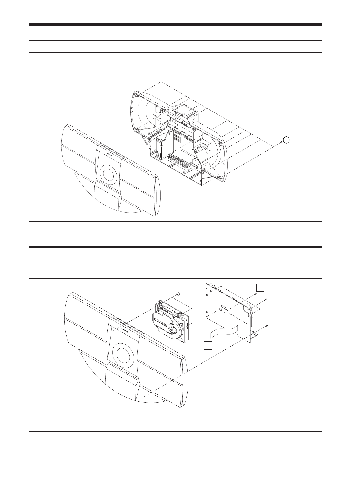
2-1 Front Cabinet
1. Remove 13 screws of ! of its rear part.(1 screw of Antenna)
2. Remove Front Cabinet to frontward.
1
Fig 2-1
1. Remove 6 screws of B its rear part
2. Remove the connect wire of C,and remove Main-PCB ASS’Y to backward.
3. Remove 3 screws of Aits rear part ,and remove CD-Mecha ASS’Y to backward.
2-2 Main-PCB ASS’Y AND CD-MECHA ASS’Y
A
B
C
Samsung Electronics
Fig 2-2

2-2
Samsung Electronics
1. Remove 2 screws of @ of its rear part.
2. Pull up Cabinet-Top Ass’y to frontward, and remove it.
Fig 2-3
2-3 Cabinet-Top ASS’Y
1. Remove Tersey-Frame of C
2. Remove 2 screws of A(Deco-Front).
3. Remove 6 screws of B (Cap-Front).
4. Remove Cap-Front Ass’y to frontward.
A
B
C
C
Fig 2-4
2-4 CAP Front ASS’Y
1. Alignment and Adjustments
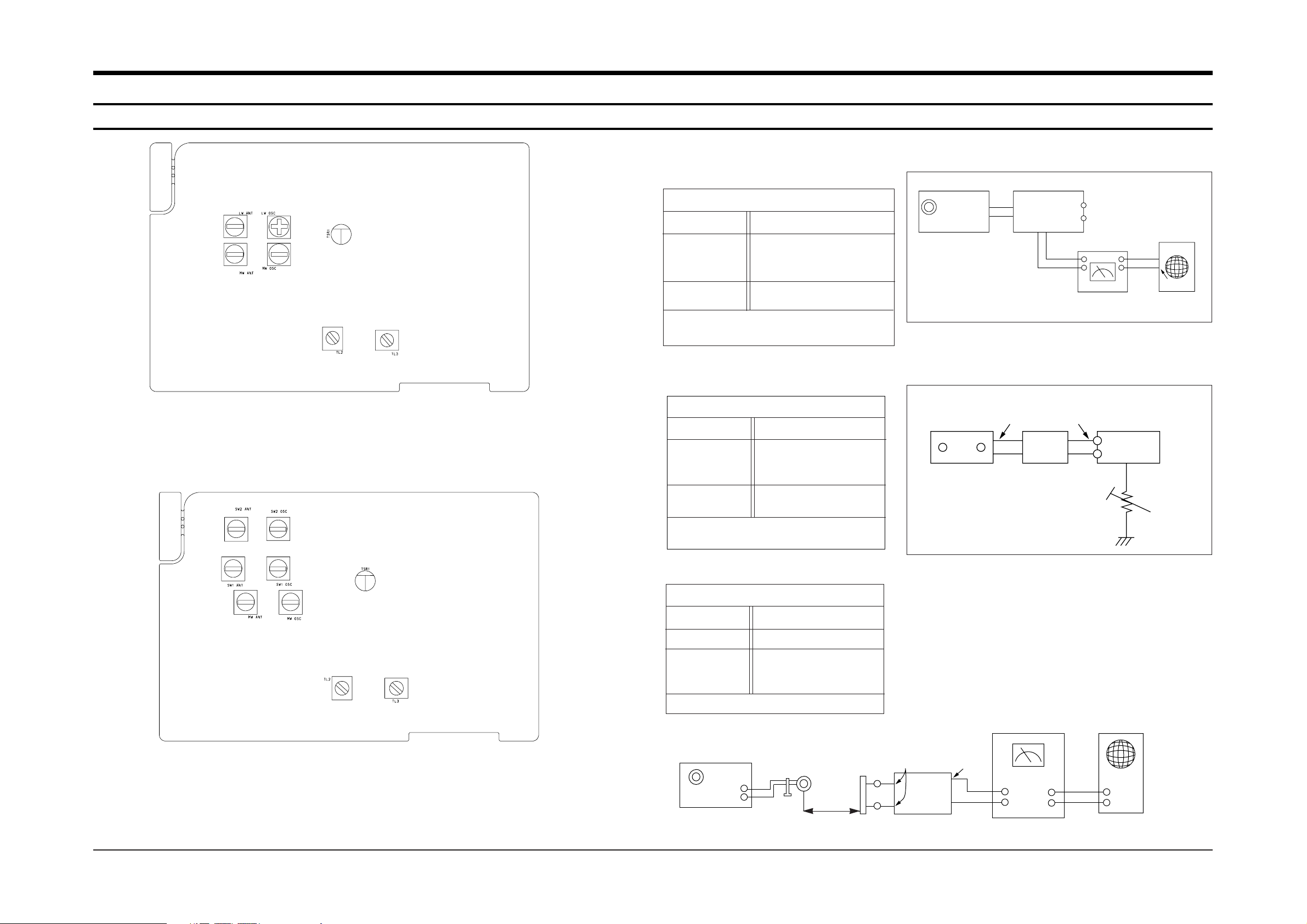
1-1 Tuner
Samsung Electronics 1-1
FM THD Adjustment
Minimum Distortion (0.4% below)
(Figure 1-3)
SSG FREQ.
Adjustment
point
(TL3)
Output
98 MHz
FM DETECTOR COIL
60dB
AM(MW)I.F Adjustment
Maximum Output(Figure 1-5)
SSG FREQ.
Frequency
Adjustment
point
(TL2)
450MHz
522MHz
AM I.F COIL
FM Search Level Adjustment
Adjust TSR1 so that “TUNED” of FLT
is lighted (Figure 1-4)
Figure1-4 FM Auto Search Level Adjustment
Figure1-5 AM I.F Adjustment
Figure1-3 IF CENTER and THD Adjustment
SSG FREQ.
Adjustment
point
(TSR1)
Output
98 MHz
BEACON
SENSITIVITY
SEMI-VR(20KΩ)
1kHz 25dB
FM SSG
GND
25 dB
FM SSG
Output
GND
Speaker
Terminal
FM
Antenna
Terminal
Distortion Meter
Input
SET
Input
output
Oscilloscope
FM IN
FM Antenna
SET
TSR1
20 kΩ
Fig1-1 Adjustment location of Tuner part(MW/LW Band)
Fig1-2 Adjustment location of Tuner part(SW1/SW2 Band)
SET
60 cm
AM Signal
Generator
Test Loop
Antenna
Speaker
Terminal
VTVM
IN
OUT
GND
Oscilloscope
AM
Loop
Antenna Jack

1-2 Samsung Electronics
1-1-1 Test Equipment
1-1-2 Pre-Adjustment
1-1-3 MW(AM)/LW/SW Adjustment
1. AM Standard Signal Generator (S.S.G) : 400Hz, 30% MOD
2. Oscilloscope
3. VTVM
4. Frequency counter
5. Loop antenna
6. Dummy load (3.2½)
7. DC voltmeter
1. Check the source voltage
2. Press TUNER/BAND to select the AM(MW) function.
3. Set the EQ/P.SOUND control to OFF position.
4. Set the volume control to approximaterly 50mw.
AM(MW)-OSC
1
2
4
5
3
594 KHz
170 KHz
Figure 1-6 MW(AM)/LW/SW Adjustment
TUNER
PCB
TP3
GND
Input
DC Voltmeter
2.3~7.3MHz
-
3.5MHz
3.5MHz
170 KHz
-
522~1611 KHz
146~290 KHz
MW OSC
1.0( ±0.1V : Adj.) ~ 7.0V( ±0.1V : Check)
Maximum output
Remark
Low Cover(Adj.)~High Cover(Check)
FREQ.
Setting
Adjust.
Point
SSG.
FREQ.
Item
Step
Alignment and Adjustments
MW
LW
SW
6
AM(MW)-RF
-
LW-OSC
LW-RF
SW1-OSC
SW1-RF
SW2-OSC
SW2-RF
7
8
-
10MHz
10MHz
9.5~26.1 MHz
594 KHz
MW ANT
LW OSC
LW ANT
SW1 OSC
SW1 ANT
SW2 OSC
SW2 ANT
Maximum output
Maximum output
Maximum output
1.0( ±0.1V : Adj.) ~ 7.0V( ±0.1V : Check)
1.0( ±0.1V : Adj.) ~ 6.5V( ±0.5V : Check)
1.0( ±0.1V : Adj.) ~ 6.5V( ±0.5V : Check)
 Loading...