

Samsung RS2534WW, RS2556SH, RS2556BB, RS2578WW, RS2578BB Service Manual
...
RS2534WW
RS2534VQ
RS2556WW
RS2556BB
RS2556SH
RS2578WW
RS2578BB
RS2578SH
Model:
SIDE-BY-SIDE REFRIGERATOR
SAMSUNG Home Appliance Service
For the latest parts information,
Please access to our service web site
(http://www.e4buyer.com/refrigerator)
2
IMPORTANT SAFETY NOTICE
The service guide is for service men with adequate backgrounds of
electrical, electronic, and mechanical experience. Any attempt to repair
a major appliance may result in personal injury and property damage.
The manufacturer or dealer cannot be responsible for the interpretation
of this information.
SAMSUNG ELECTRONICS AMERICA, INC.
Technical Service Guide
Copyright ⓒ2004
All rights reserved. This service guide may not be reproduced in whole or in
part in any form without written permission from the SAMSUNG ELECTRONICS
Company.
WARNING

3
Contents
1. Introduction ········································ 4
2. Installation
········································
5
3. Nomenclature
·······································
6
4. Specifications
·······································
7
5. Warranty information
···································
8
6. Interior Views and Dimensions
·····························
9
7. Refrigeration Cycle and Cool Air Circulation Route
·················
11
8. Mechanical Disassembly
································
13
9. Operation Function
····································
23
10.
Circuit Descriptions
···································
37
11. Diagnostics
·······································
46
12. Illustrated Parts Catalog
································
58
13. Safety instruction on services
·····························
72
●
Appendix ⅠⅠ(Reference for circuit diagnostics)
····················
73
●
Appendix ⅡⅡ(Circuit diagram)
······························
79
4
1. INTRODUCTION
●●
A newly developed SAMSUNG side by side refrigerator in 2004 has the following
characteristics.
1) T win Cooling System
·The refrigerator and the freezer have two
evaporators. Given this independent system, the
freezer and the refrigerator are cooled individually as
required and are, therefore, more efficient. Food
odor from the refrigerator does not affect food in the
freezer due to separate air flow circulation.
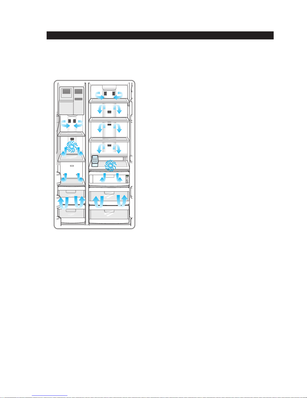
2) Multi-Flow System
·Cool air circulates through multiple vents on every
shelf level. This provides even distribution of cooling
inside cabinets to keep your food fresh longer.
3) Xtra Space
TM
·V ertical room next to the ice maker in the freezer
provides space for pizza etc.
4) Door Alarm
·Beep sound reminds you the door is open.
5) Xtra Fresh
TM
·Optimized humidity control keeps vegetables & fruits
fresh.
6) Deodorizer
·Reusable twin deodorizers keep the refrigerator air
fresh and odor free.
7) CoolSelect Zone
TM
Drawer(RS2556, RS2578)
·User can select Quick Cool, Thaw , for quickly chill
items, thaw items. Select Soft freeze, Chill or Cool to
control the temperature of the drawer.
5
2. INSTALLATION
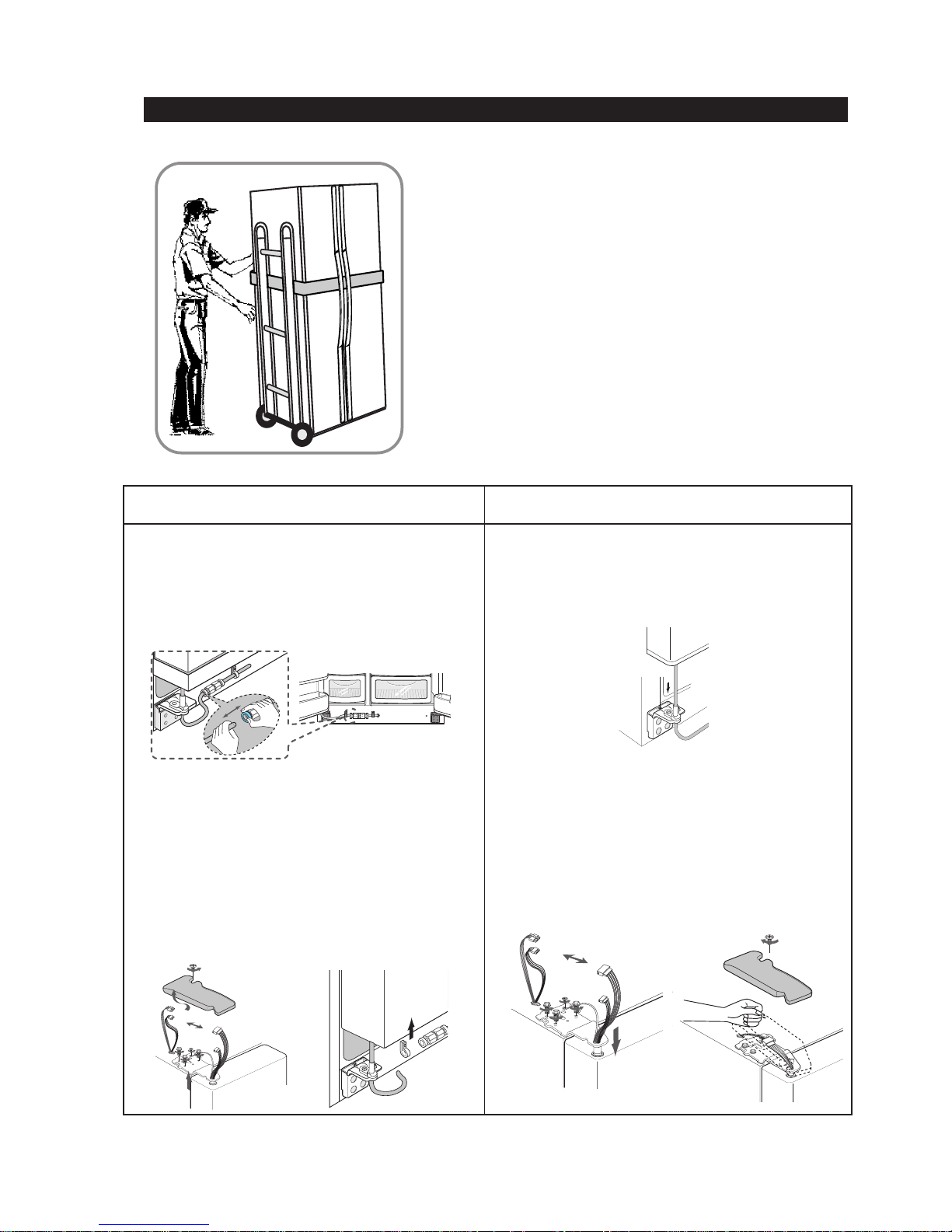
1) T o protect refrigerator in movement
Use padded hand truck as shown. If entrance width is
less than 39〃, remove doors prior to installation and
reattach doors according to procedure below.
2) Remove all protective tape and pad in refrigerators.
Connect water lines and power cord. Adjust the
clearance between the doors.
3) Set the temperature control to the temperature and
wait for an hour.
The refrigerator should get slightly chilled and the motor
runs smoothly .
4) Once the refrigerator temperature is sufficiently low
You can store food in the refrigerator. After starting the
refrigerator, it takes a few hours to reach the appropriate
temperature.
●●
Removing Doors
Open the freezer and refrigerator doors, and
then take off the front leg cover assembly by
turning the three screws counter-clockwise.
Remove the screw from clamp disconnect, the
water tube by pressing the coupler, and pulling
the water tube away .
With the door closed, remove the upper hinge
cover using a screwdriver, and then disconnect
the wires. Remove hinge screws and ground
screw counter-clockwise, and take off the upper
hinge. Take care removing the door to ensure that
it does not fall on you.
Remove the door from the lower hinge by
carefully lifting the door so as not to damage the
water tube. Remove the lower hinge from the
lower hinge bracket by lifting the lower hinge.
●●
Attaching Doors
Insert the lower hinge in the bracket lower
hinge. Attach the freezer door by inserting the
hose in the lower side of the door into the hole in
the lower hinge and pulling the hose down.
Insert the upper hinge shaft into the hole. After
leveling between the upper hinge hole and the
hole of the cabinet. Reattach hinge screws and
screw in the clockwise direction. Connect the
wires. Put the front part of the upper hinge cover
on the front part of the upper hinge and reattach
from the front part of the upper hinge cover first.
6
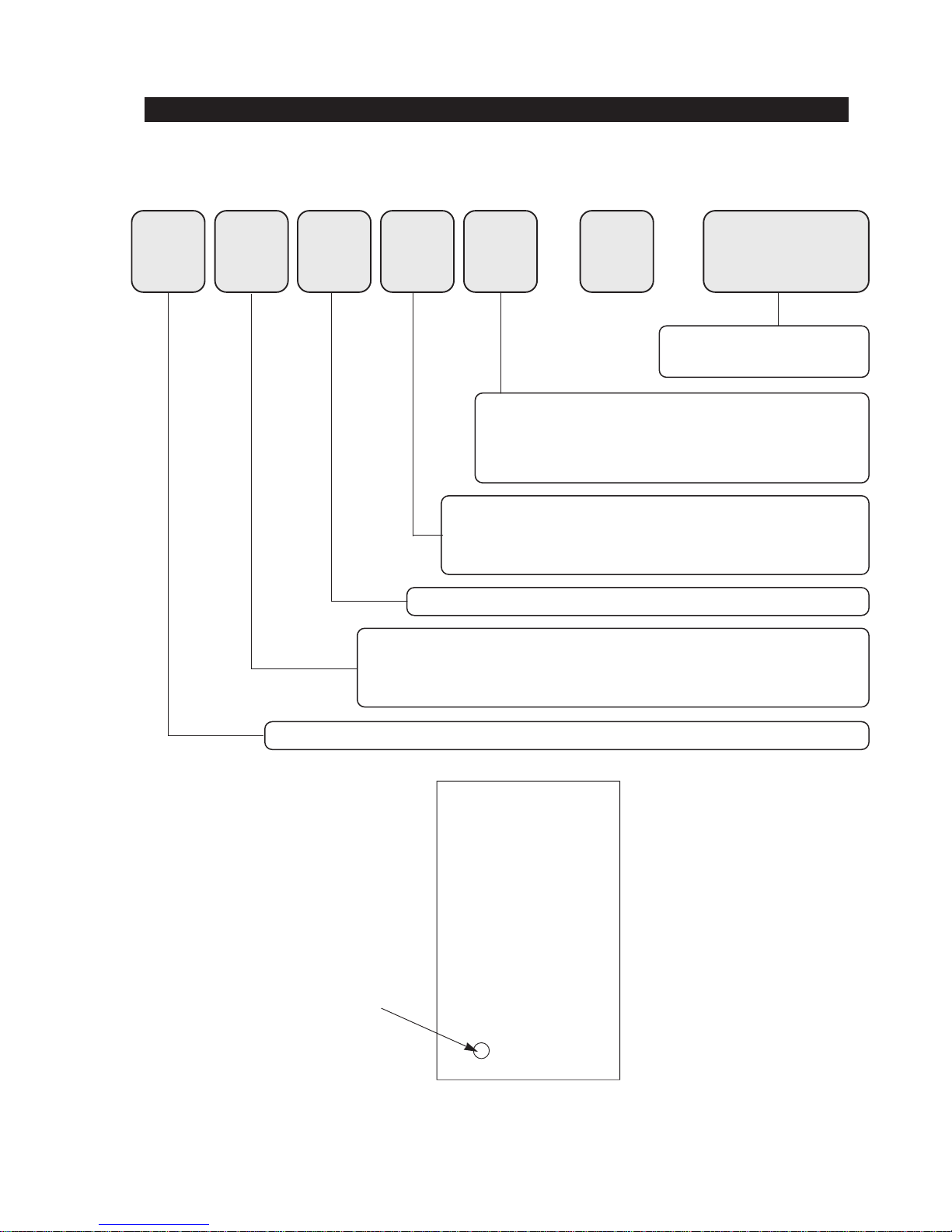
3. Nomenclature
R S 25 34 SL / XAA
Product ; R - REFRIGERATOR
Capacity ; CU. FT
Family ; S - SIDE BY SIDE (SBS)
H - HomePADTM(SIDE BY SIDE)
B - BOTTOM MOUNTED FREEZER (BMF)
OPTION ; SBS 34-GOOD 56-BETTER 78-BEST
BMF 55-NO DISPENSER 77-DISPENSER
COLOR ;
SBS SW-SNOW WHITE
SL-NOBLE STAIN
SH-
STAINLESS PLATINUM
WW-SMOOTH WHITE
VQ-BISQUE BB-BLACK
BMF SW-SNOW WHITE
SL-NOBLE GRAY
Buyer Code
Label Location
4. Specifications
Defrost Control From 24 to 32 hrs
Defrost Thermistor(502AT) 50℉(off)
Electrical Rating AC115V 60Hz 11.6 Amps
Maximum Current Leakage 0.25 mA
Maximum Ground Path Resistance 0.1 Ohm
Energy Consumption KWH/mo.
Ambient Temperature 70
℉ 90℉
Refrigerator,℉ 34∼46 34∼46
Freezer,℉ -14∼8 -14∼8
Run Time,% 40 60
Refrigerant Charge (R134a) 7.76 oz
Compressor(MK183C-L2U) 532.3 Btu/hr
Compressor oil Freol α-15
Capillary tube(Dia, Length)
0.033"",130
""
Dryer
Molecular Sieve XH-9
Clearance must be provided for air circulation
AT TOP 2
""
AT SIDES 0.1
""
AT REAR 2
""
RS2534(Good), RS2556(Better), RS2578(Best)
Main Board(RS2534) DA41-00134F
Main Board(RS2556,2578) DA41-00104M
Thermistor(Freezer) DA32-10109W
Thermistor(Freezer Evaporator) DA32-00006A
Thermistor(Refrigerator) DA32-10105U
Thermistor(Refrigerator Evaporator)
DA32-00006B
Thermistor(Ambient) DA32-10109V
Thermistor(CoolSelect ZoneTM)
DA32-10109X
Thermistor(Ice-Maker)
DA32-10108B
Relay DA35-10013Q
Overload Relay DA34-10003D
Run Capacitor (12㎌) 2501-001045
Fan-Motor(FRE) DA31-00020E
Fan-Motor(REF) DA31-00002S(RS2534)
Fan-Motor(REF) DA31-00020E(RS2556/2578)
Fan-Motor(Condenser) DA31-00020H
Thermal Fuse DA47-00095C
Senser-Flow DA32-10110B
Fan
Fan
Fan
Fan
Fan
Fan
(Air inlet)
(Air inlet)
(Air inlet)
(Air inlet)
(Air inlet)
(Air inlet)
Heat exchanger
Heat exchanger
Heat exchangerHeat exchanger
Compressor
Dryer
C-Fan
Electric box
Sub-condenser
ELECTRICAL SPECIFICA TIONS Freezer Refrigerator
NO LOAD PERFORMANCE
REFRIGERA TION SYSTEM
INST ALLATION
MODELS
REPLACEMENT P ARTS
7

8
5. Warranty information
LIMITED W ARRANTY T O ORIGINAL PURCHASER
SAMSUNG REFRIGERATOR
(18 Cubic Feet and Larger Capacity)
This SAMSUNG brand product, as supplied and distributed by Samsung Electronics America, Inc. (SAMSUNG) and delivered new,
in the original carton to the original consumer purchaser, is warranted by SAMSUNG against manufacturing defects in materials
and workmanship for a limited warranty period of:
One (1) Year Parts and Labor on Refrigerator
Five (5) Years Parts and Labor on Sealed Refrigeration System Only*
(*Compressor, evaporator, condenser, Dryer, connecting tubing)
This limited warranty begins on the original date of purchase, and is valid only on products purchased and used in the United
States. To receive warranty service, the purchaser must contact SAMSUNG for problem determination and service procedures.
Warranty service can only be performed by a SAMSUNG authorized service center. The original dated bill of sale must be
presented upon request as proof of purchase to SAMSUNG or SAMSUNG's authorized service center.
SAMSUNG will repair or replace any part found to be defective, at our option and at no charge as stipulated herein, with new or
reconditioned parts during the limited warranty period specified above. All replaced parts and products become the property of
SAMSUNG and must be returned to SAMSUNG. Replacement parts and products assume the remaining original warranty, or
ninety (90) days, whichever is longer.
In-home service will be provided during the warranty labor period subject to availability within the contiguous United States. Inhome service is not available in all areas. To receive in-home service, the product must be unobstructed and accessible from floor
level to service personnel. If during in-home service repair cannot be completed, it may be necessary to remove, repair and return
the product. If in-home service is unavailable, SAMSUNG may elect, at our option, to provide for transportation of our choice to
and from a SAMSUNG authorized service center. Otherwise, transportation to and from the SAMSUNG authorized service center
is the responsibility of the purchaser.
This limited warranty covers manufacturing defects in materials and workmanship encountered in normal, noncommercial use of
this product, and shall not apply to the following, including, but not limited to: damage which occurs in shipment; delivery and
installation; applications and uses for which this product was not intended; altered product or serial numbers; cosmetic damage or
exterior finish; accidents, abuse, neglect, fire, water, lightning or other acts of nature; use of products, equipment, systems, utilities,
services, parts, supplies, accessories, applications, installations, repairs, external plumbing and leaks, external wiring, circuit
breakers, fuses or connectors not supplied and authorized by SAMSUNG, or which damage this product or result in service
problems; incorrect electrical line voltage, fluctuations and surges; customer adjustments and failure to follow operating instructions,
cleaning, maintenance and environmental instructions that are covered and prescribed in the instruction book; loss of food due to
spoilage; consumable items including filters and light bulbs.
THERE ARE NO EXPRESS WARRANTIES OTHER THAN THOSE LISTED AND DESCRIBED ABOVE, AND NO WARRANTIES
WHETHER EXPRESS OR IMPLIED, INCLUDING, BUT NOT LIMITED TO, ANY IMPLIED WARRANTIES OF
MERCHANTABILITY OR FITNESS FOR A PARTICULAR PURPOSE, SHALL APPLY AFTER THE EXPRESS WARRANTY
PERIODS STATED ABOVE, AND NO OTHER EXPRESS WARRANTY OR GUARANTY GIVEN BY ANY PERSON, FIRM OR
CORPORATION WITH RESPECT TO THIS PRODUCT SHALL BE BINDING ON SAMSUNG. SAMSUNG SHALL NOT BE
LIABLE FOR LOSS OF REVENUE OR PROFITS, FAILURE TO REALIZE SAVINGS OR OTHER BENEFITS, OR ANY OTHER
SPECIAL, INCIDENTAL OR CONSEQUENTIAL DAMAGES CAUSED BY THE USE, MISUSE OR INABILITY TO USE THIS
PRODUCT, REGARDLESS OF THE LEGAL THEORY ON WHICH THE CLAIM IS BASED, AND EVEN IF SAMSUNG HAS BEEN
ADVISED OF THE POSSIBILITY OF SUCH DAMAGES. NOR SHALL RECOVERY OF ANY KIND AGAINST SAMSUNG BE
GREATER IN AMOUNT THAN THE PURCHASE PRICE OF THE PRODUCT SOLD BY SAMSUNG AND CAUSING THE
ALLEGED DAMAGE. WITHOUT LIMITING THE FOREGOING, PURCHASER ASSUMES ALL RISK AND LIABILITY FOR LOSS,
DAMAGE OR INJURY TO PURCHASER AND PURCHASER’S PROPERTY AND TO OTHERS AND THEIR PROPERTY
ARISING OUT OF THE USE, MISUSE OR INABILITY TO USE THIS PRODUCT SOLD BY SAMSUNG NOT CAUSED DIRECTLY
BY THE NEGLIGENCE OF SAMSUNG. THIS LIMITED WARRANTY SHALL NOT EXTEND TO ANYONE OTHER THAN THE
ORIGINAL PURCHASER OF THIS PRODUCT, IS NONTRANSFERABLE AND STATES YOUR EXCLUSIVE REMEDY.
Some states do not allow limitations on how long an implied warranty lasts, or the exclusion or limitation of incidental or
consequential damages, so the above limitations or exclusions may not apply to you. This warranty gives you specific legal rights,
and you may also have other rights, which vary from state to state.
To obtain warranty service, please contact SAMSUNG at:
SAMSUNG CUSTOMER CARE CENTER
400 Valley Road, Suite 201, Mt. Arlington, NJ 07856, Tel: 973-601-6000, Fax: 973-601-6001
1-800-SAMSUNG (1-800-726-7864) and www.SAMSUNGUSA.com
061002
9
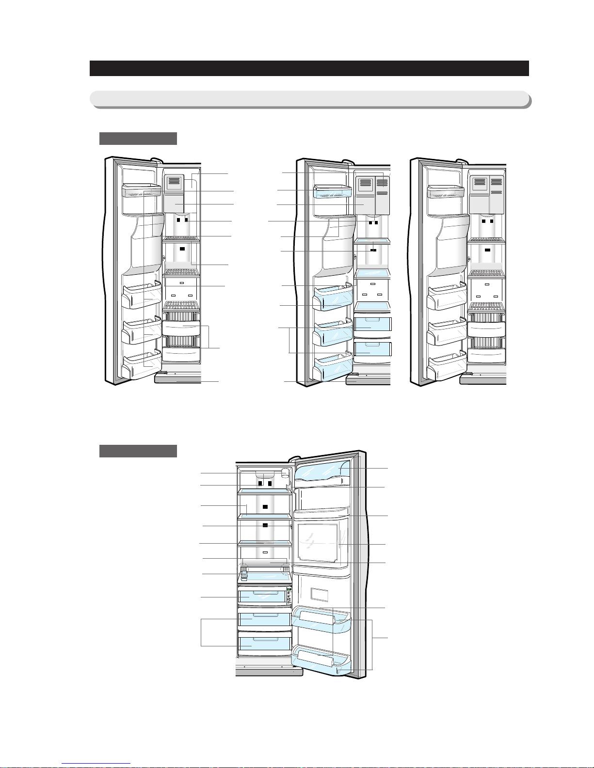
6. Interior Views and Dimensions
6-1) Shelves and Bins
Freezer
Refrigerator
Door Bin
Xtra Space
TM
Ice Maker
Light
Ice Chute
Glass Shelf
Wire Shelf
Light Switch
Light Switch
Deodorizer
Plastic Drawers
Wire Drawers
Front Leg Cover
Tilt Pockets
RS2534 Model
Egg Container
Foldable Shelf (RS2578)
Light (upper)
Water Filter
Spill-proof glass Shelf
Dairy Compartment
Wine Self (RS2578)
Gallon Door Bin
Beverage StationTM(RS2578)
Lights (lower) (RS2556,2578)
Gallon Door Bins
Door Bin Top Lips
CoolSelect Zone
TM
Drawer
( Chilled Bin for RS2534)
Vegetable & Fruit Drawers
RS2578 Model
CoolSelect Zone
TM
RS2556 Model
CoolSelect Zone
TM
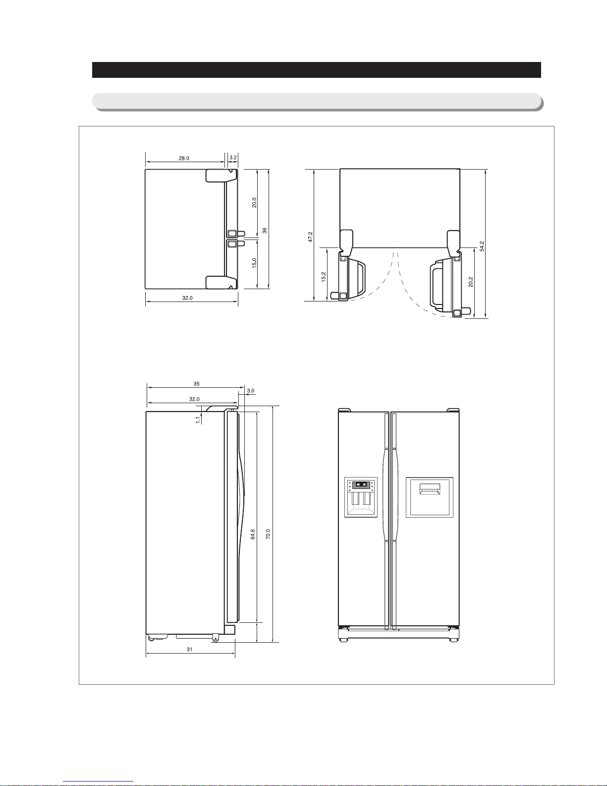
10
Interior Views and Dimensions
6-2) Dimensions of Refrigerator(RS2534/2556/2578) (Inches)
Beverage Station
TM
(RS2578)
11
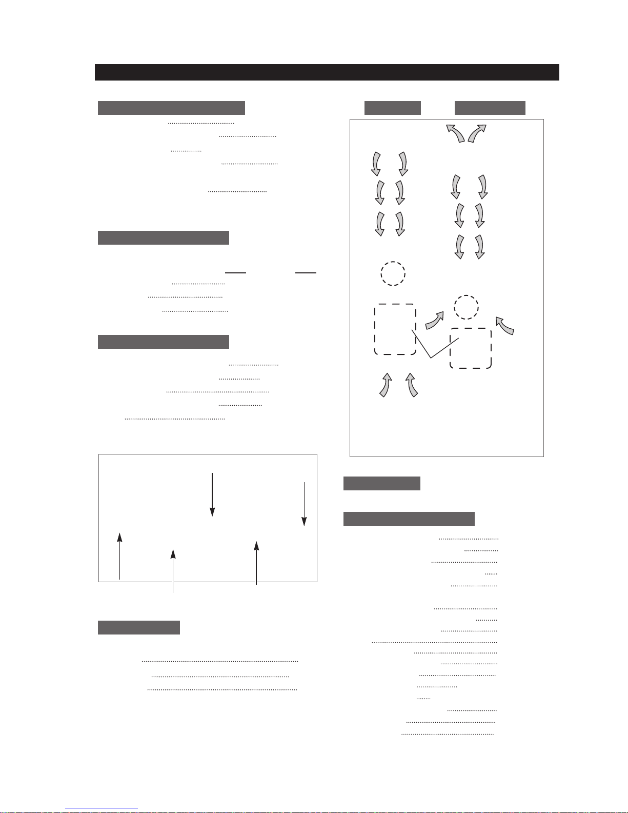
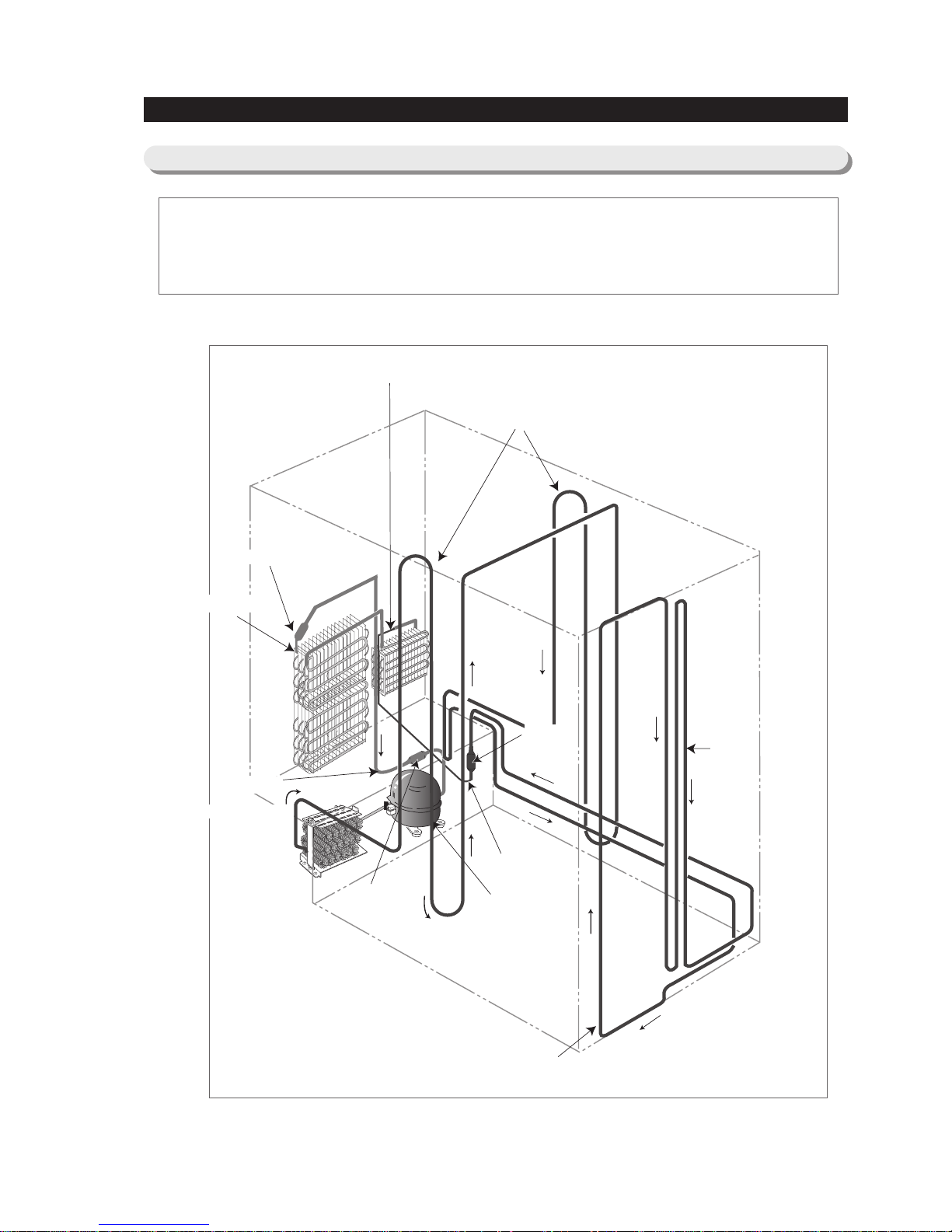
Compressor → Sub-condenser → Side Cluster Pipe(FRE) → Side Cluster Pipe(REF) → Hot Pipe
→ Dryer → Capillary Tube → Refrigerator Evaporator → Freezer Evaporator→ Suction Pipe → Compressor
Refrigerator Evaporator
Capillary Tube
ACCUMULATOR
Freezer Evaporator
SUCTION PIPE
Dryer
Muffler
SUB-CONDENSER
Hot Pipe
Hot Pipe
Compressor
SIDE CLUSTER PIPE
7. Refrigeration Cycle and Cool Air Circulation Route
7-1) Refrigerant Route in Refrigeration cycle
12
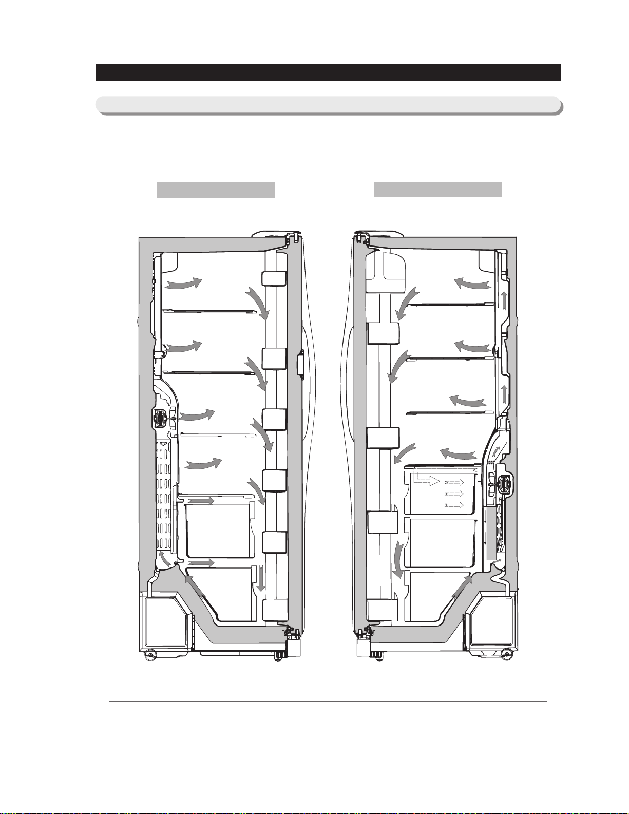
Refrigeration Cycle and Cool Air Circulation Route
7-2) Cool Air Circulation
Freezer
Refrigerator

13
8-1) Refrigerator Disassembly
8-2) Freezer Disassembly
8-1) Refrigerator Disassembly
8. Mechanical Disassembly
Control Panel ········································ 14
Door Handle ········································ 14
Beverage Station
TM
····································· 14
Door Gasket········································· 14
Refrigerator Door Light Switch ······························ 15
Refrigerator Light ······································ 15
Tempered Glass Shelf ··································· 15
Plastic Drawers in Refrigerator ······························ 15
Gallon Door Bin ······································· 15
Water Filter ········································· 16
Evaporator Cover in the Refrigerator ·························· 16
Upper Ductwork ······································ 16
Evaporator Fan Motor ··································· 16
Evaporator in Refrigerator ································· 17
Refrigerator Thermistor ·································· 17
CoolSelect Zone
TM
Thermistor ······························ 17
Door Bin in Freezer ···································· 18
Freezer Door Light Switch ································ 18
Plastic(Wire) Drawer in Freezer······························ 18
Freezer Shelf ········································ 18
Ice Dispenser & Ice Maker ································ 18
Auger Motor Case ····································· 19
Freezer Light ········································ 20
Evaporator Cover in Freezer ······························· 20
Upper Ductwork······································· 20
Evaporator Fan Motor ··································· 20
Evaporator in Freezer ··································· 21
Freezer Thermistor ····································· 21
Ambient Thermistor····································· 21
Ice-Maker Thermistor···································· 21
Machine Compartment & Electrix Box ··························22
Water Solenoids ······································ 22
Condenser Fan ······································· 22
Sub-condenser ······································· 22
14
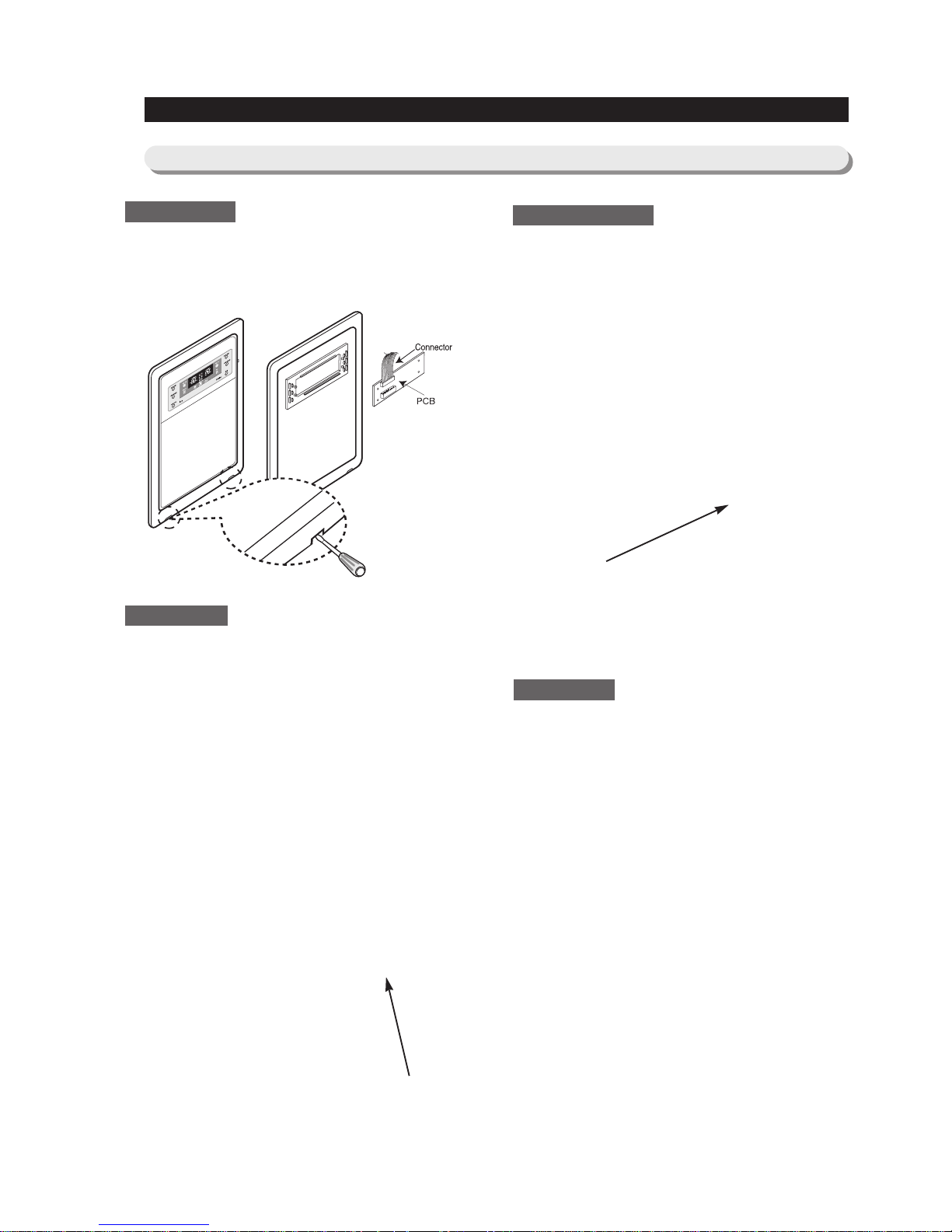
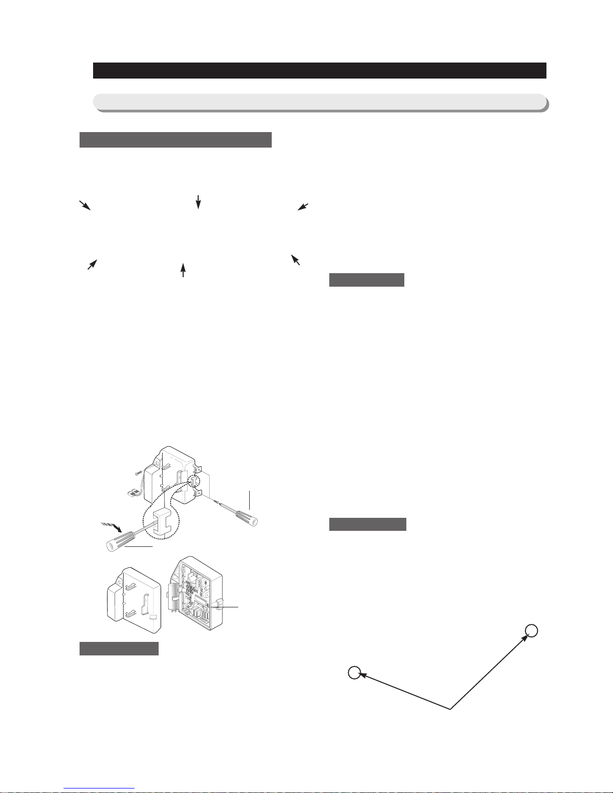
88.. MMeecchhaanniiccaall DDiissaasssseemmbbllyy
1. Insert a flat-blade screwdriver on the slot as shown,
and unlock the tabs.
2. Disconnect the wire connector.
The door handles allow access into the refrigerator
and freezer. They are front mounted with Phillips
head screws.
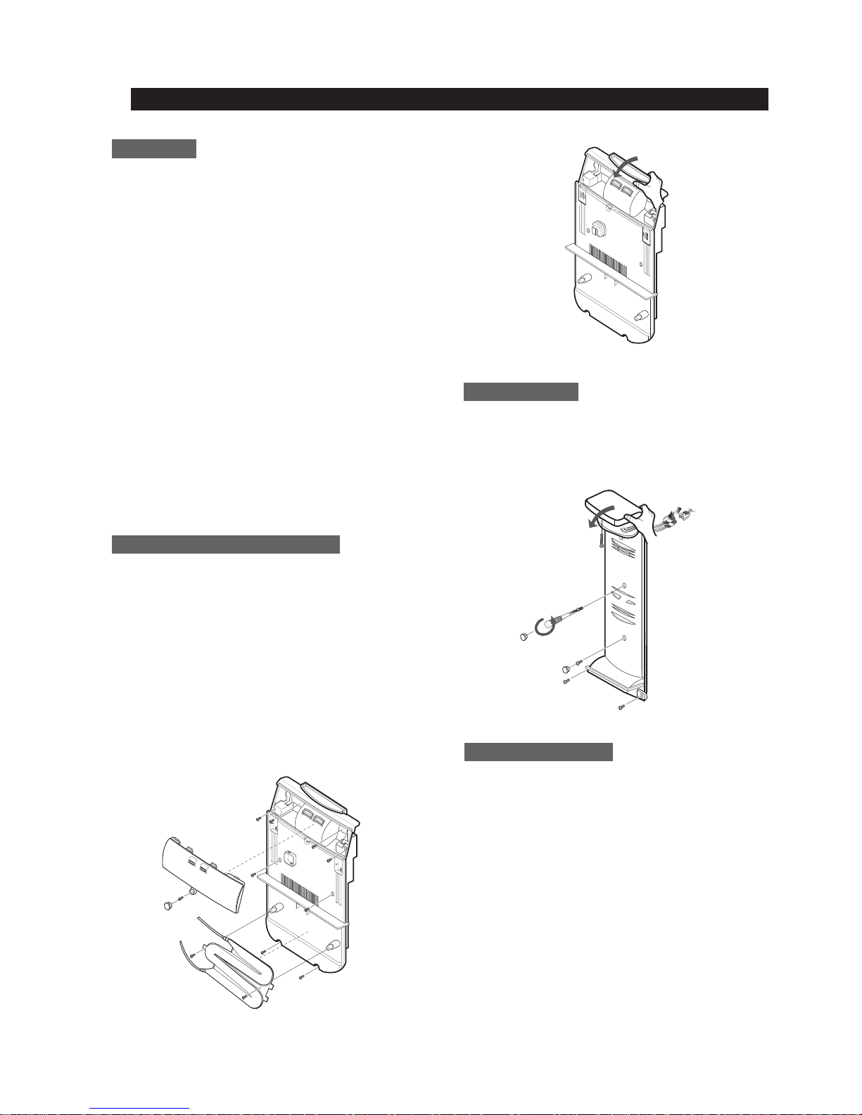
1. With a small flat-blade screwdriver, press the
small button and pull handle cover out.
2. Remove the Phillips screws (8).
3. Lift the handle with an in and upward motion until
it disengages the locking tabs. Pull the handle
outward to remove it.
The beverage station
TM
allows access to the
refrigerator without opening the refrigerator door.
1. Open the door beverage station
TM
2. With a small flat-blade screwdriver,take out the
rubbercap, then put it into the small hole and
push the button inside.
3. Take off its door.
The door gasket is a molded gasket set into a
channel located in the door liner.
1. Open the door.
2. Grasp the gasket and pull in an outward motion
until the molded gasket separates from the door
liner.
Control Panel
Door Handle
Beverage Station
TM
Door Gasket
Button
8-1) Refrigerator Disassembly
15
MMeecchhaanniiccaall DDiissaasssseemmbbllyy
The refrigerator has a door light switch located in
the upper right corner for the refrigerator.
1. Use a small flat-blade screwdriver to unlock the
locking tab and pull the switch out until the
wire connector is visible.
The refrigerator lights are located in the upper and
lower portion of refrigerator.
1. Pull out the screw cap and remove the screw.
2. To access the lower lights, pull out the screw cap
and remove the screw.
3. Remove the lamp cover by unlocking the tabs
and pulling the cover down.
These shelves allow the storage of larger items and
pull out for easy access.
1. Pull the shelf out as for as it goes.
2. Lift it up and remove it.
Drawers are designed for storage of fruits,
vegetables, and deli items. The drawers are located
in the lower portion of the refrigerator.
1. Pull out the drawer as far as it goes.
2. Tilt the drawer up and pull it out until it is
removed.
The door bins allow storage of perishable items.
1. Push the bin up and slide it out.
Refrigerator Door Light Switch
Gallon Door Bin
T empered Glass Shelf
Plastic Drawers in Refrigerator
Refrigerator Light
16
MMeecchhaanniiccaall DDiissaasssseemmbbllyy
The water filter is located in the upper right-hand
corner of the refrigerator. The water filter filters water
for the ice maker and the water dispenser.
1. Turn the water filter 1/2 turn counterclockwise and
pull it down.
2. To install the filter, align the indication mark
(unlock position) and push it up while turning 1/2
turn clockwise until the lock position is aligned.
Do not over tighten.
1. Pull out the screw cap and remove the screw.
2. Remove the lamp cover by unlocking the tabs
and pulling the cover down.
3. Remove the water tank from the evaporator cover
by unscrewing the screws (2).
4. Remove the screws (6) at the evaporator cover
and the two fixed screws of the wire connector
cover.
5. Take off motor and lamp wire connector located
on the upper liner.
6. Remove the duckwork of the evaporator fan in the
direction of the arrow as shown.
1. Remove the screw caps (2) and screws (5).
2. Slide the upper fan ductwork out while
disconnecting the wire connector(lamp and
thermistor).
The evaporator fan is located in the middle rear of
the freezer. This fan circulates cold air in the freezer.
1. Remove screws (4) located at the four corners of
the fan bracket.
2. Take the fan motor assembly off.
Water Filter
Evaporator Cover in the Refrigerator
Upper Ductwork
Evaporator Fan Motor

17
MMeecchhaanniiccaall DDiissaasssseemmbbllyy
Evaporator is located in the bottom of refrigerator.
1. Take off the ductwork in refrigerator.
2. Disconnect the wire connector.(Heater and
Thermistor)
3. Desolder the capillary tube and the suction line
from the evaporator.
4. Remove the evaporator.
5. With a file, score the capillary tube just upstream
of the soldered point. Break off the soldered
section to help prevent solder from plugging the
tube during soldering.
6. Place a new evaporator and braze the suction
and capillary tube to evaporator using silver
solder.
7. Install a replacement dryer.
8. Evacuate and recharge the system using
reasonable procedures.
The refrigerator thermistor is located inside of the
upper light cover of the refrigerator.
The CoolSelect Zone
TM
thermistor is located outside
the back of CoolSelect Zone
TM
drawer. The
temperature signal sends the micro-processor.
Refrigerator ThermistorRefrigerator Thermistor
CoolSelect ZoneTMThermistor
Thermistor
Thermistor
Thermistor
Suction Line
Capillary Tube
Thermal Fuse
Evaporator in Refrigerator
The door bins allow storage of perishable items.
1. Push the bin up and slide it out.
This switch is located in the left-hand portion of the
freezer and sends a signal to the processor.
1. With a small flat-blade screwdriver, unlock the
locking tabs and pull the switch out until the wire
connector is visible.
2. Disconnect the wire connector and remove the
switch.
Drawers are designed for storage of meat and dry
foods. The drawers are located in the lower portion of
the freezer.
1. Pull out the drawer as far as it goes.
2. Tilt the drawer up and pull it out until it is
removed.
The shelves slide out for easy access for frozen
items.
1. Slide the shelf out until it reaches its stop.
2. Tilt down and slide it out of thecompartment.
The ice dispenser is located in the upper portion of
the freezer. This assembly stores ice made by the
icemaker and dispenses ice.
1. Lift the ice bucket up ① and slide out the ice
dispenser assembly ②.
18
Door Bin in Freezer
MMeecchhaanniiccaall DDiissaasssseemmbbllyy
8-2) Freezer Disassembly
Freezer Shelf
Plastic (Wire) Drawer in Freezer
Freezer Door Light Switch
Ice Dispenser &&Ice Maker
19
MMeecchhaanniiccaall DDiissaasssseemmbbllyy
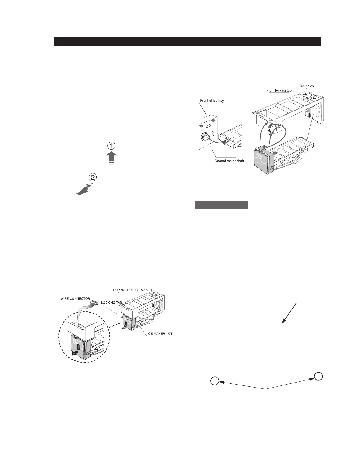
The ice maker is located inside of the ice dispenser
assembly.
1.
Remove ice maker support screws (2), and slide out.
2. Disconnect the ice maker wire connector.
3.
Unlock the locking tabs to separate the ice maker kit.
In order to assemble the icemaker kit.
1. Assemble the geared motor shaft and the front of
ice tray.
2. Lift the front locking tab and assemble the ice
maker kit.
3. Connect the ice maker wire connector.
4. Match the tab holes and tabs(2) located on the
top of the liner, and slide the ice maker in.
5. Tighten the screws (2) of the ice maker support.
This shelf is designed to support the ice maker &
ice dispensed and Xtra Space
TM
.
1. Remove the Xtra Space
TM
cover to push it down
and pull front.
2. Slide the partition out.
3. Remove the screws (2) on the bottom front of the
case.
4. Slide out the case while disconnecting the wire
connect.
Auger Motor Case
Partition
Screws
20
The freezer light is located in the bottom of the
auger motor case. The light is covered by an opaque
cover.
1. Remove the screw and the light cover.
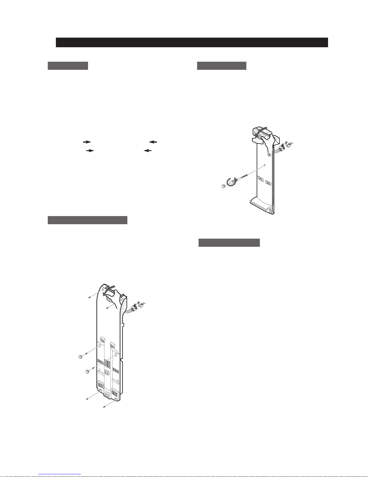
1. Pull out the screw caps and remove screws (6).
2. Remove the ductwork of the evaporator fan in the
direction of the arrow as shown.
3. Disconnect the wire connector.
1. Remove the screw cap and screw.
2. Slide the upper fan ductwork out while
disconnecting the wire connector (Lamp and
Thermistor).
The evaporator fan is located in the lower rear of
refrigerator. This fan circulates cold air in the
refrigerator.
1. Remove screw(4) located at the four corners of
the fan bracket.
2. Take the fan motor assembly off.
Upper Ductwork
Evaporator Fan Motor
Freezer Light
Evaporator Cover in Freezer
MMeecchhaanniiccaall DDiissaasssseemmbbllyy
21
Evaporator is located in the bottom of freezer to
produce cold air driven across the evaporator coils.
1. Take off the ductwork in Freezer.
2. Disconnect the wire connector (Heater, Bimental,
and Thermistor).
3. Desolder the inlet and outlet tubes.
4. Remove the evaporator.
5. Take the same steps to seal the system as
mentioned earlier.
The freezer thermistor is located at the top left of
freezer vent. It sends temperature signals to the
micro-processor.
The ambient thermistor is located inside the upper
hinge cover. It sends temperature signals to the
micro-processor.
The Ice-Maker thermistor is located in its bottom.
The temperature signal sends the micro-processor.
Evaporator in Freezer
MMeecchhaanniiccaall DDiissaasssseemmbbllyy
Accumulator
Thermistor
Thermal
Fuse
Freezer Thermistor
Ambient Thermistor
Ice-MakerThermistor
Freezer Thermistor
Ambient
Thermistor
Thermistor(ICE-MAKER
)
22
1. Disconnect the power cord of the refrigerator
.
2. Remove the fixed screws (6) of compressor
cover.
3. Slide up and take off the compressor cover to
see the machine compartment.
4. Press the tab in electric box cover to take out
by using a flat-blade screw driver.
When the solenoids receive a signal from the microprocessor, they supply water to the water dispenser
or the ice maker.
1. Remove bracket screw (1) on electric box.
2. Take the solenoids assembly out.
3. Disconnect water tubes (3).
The condenser Fan is located in the middle of
machine compartment. It cools down the subcondenser and the compressor.
1. Disconnect the condenser fan wire.
2. Remove screw (1) on the drain water tray.
3. Take the condenser fan assembly off.
The sub-condenser is located in the machine
compartment. The heat is extracted by condenser
fan.
1. Desolder the compressor discharge &
the sub-condenser outlet.
2. Take out the sub-condenser.
Machine Compartment &&Electric Box
MMeecchhaanniiccaall DDiissaasssseemmbbllyy
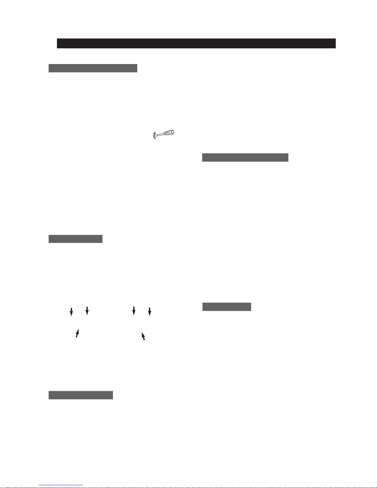
8-3) Machine Compartment Disassembly
(+)driver
(-)driver
PCB-MAIN ASSY
Water Solenoids
Condenser Fan
Sub-condenser
Desoldering Point

23
9. Operation Function
9-1) Digital Panel ······································ 24
9-2) Temperature Control Function
···························· 24
9-3) Power Freeze and Power Cool Functions
····················· 25
9-4) Child Lock Function
·································· 25
9-5) Ice & Water Dispenser Function
·························· 26
9-6) C-Fan Motor Delay Function of the Machine Compartment
···········26
9-7) CoolSelect Zone
TM
Function(RS2556, RS2578) ·················· 26
9-8) Water Filter Indicator Function
···························· 27
9-9) Ice-Maker Function
·································· 27
9-10) Defrost Function
··································· 29
9-11) Forced Operation Function (Pull-down/R-Defrost/R,F-Defrost/Cancellation)
· 30
9-12) Sound Function
··································· 31
9-13) Exhibition Function
································· 31
9-14) Self-Diagnostics Function
······························ 31
9-15) Load Operation Check Function
·························· 33
9-16) Restoration Function for Power Outage
······················ 33
9-17) Set Point Shift Function
······························· 33
9-18) Table of Set Point Shift Function
·························· 34
24
9. Operation Function
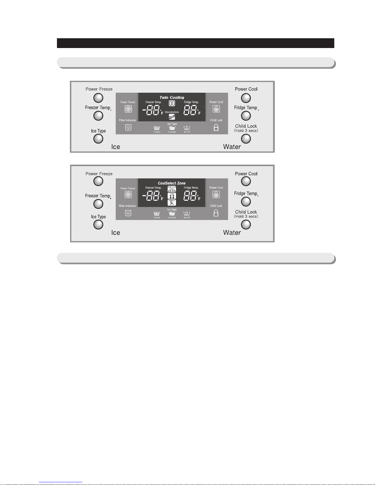
9-1) Digital Panel
When the system power is initally engaged, the default set temperature are -4℉ for the freezer and 38℉ for the set
refrigerator, respectively. The numbers shown on the digital display panel stand for the actual compartments
temperatures. When the compartment temperatures go down, so do the numbers on the display panel, and finally they
reach the set temperatures. Once the system is stabilized, the display temperatures are the set temperature.
1) Freezer Temperature Control.
To select a set temperature, press the Freezer Temp. button. The display shows the set temperature from -14℉ to
8 ℉ in sequence.
2) Quick Ice Freezer Temperature Control
Interior Temperature of the freezer will be controlled with -14 degrees Fahrenheit until the ice bucket is filled up with
ice cubes. When the ice bucket is filled up with ice cubes, the freezer will run with original set temperature. Also,
whenever the ice bucket is released from being filled with ice cube, the freezer will repeat
to be controlled with -14 degrees Fahrenheit. But if you select "Ice Off, the freezer always will be controlled with
original set temperature.
3) Refrigerator Temperature Control.
To select a set temperature, press the Fridge Temp. button. The display shown the set temperature from 34℉ to
46℉ in sequence.
note) Because of the temperature sensor sensivity, the refrigerator can be under and/or over cooled when
the air flow is blocked by stored foods. (Temperature range of the sensor : 15℉∼80℉)
In the event of a power failure, if the freezer temperature is maintained lower than 41℉, the last
selected set temperature and functions memorized in EEPROM will be restored when the power is on.
for RS2534
for RS2556
RS2578
9-2) T emperature Control Function

25
Operation Function
9-3) Power Freeze and Power Cool Functions
9-4) Child Lock Function
● Select the Power Freeze or Power Cool buttons separately.
● These buttons are toggled ON and OFF and the indicators as well.
● Although you select Power Freeze or Power Cool, the set temperatures in the freezer and refrigerator are not
changed.
● The set temperatures for the compartments can be changed while these functions are in use.
1) Power Freeze function
1-1) When you press the Power Freeze button, the LED indicator lights right away, but there is 10 seconds lag time
to an actual
operation. When this button is pressed again, the Power Freeze function stops and the indicator is off
immediately .
1-2) If you select Power Freeze, both the compressor and the freezer fan run for 2.5 hours continuously .
1-3) During Power Freeze, the freezer retains the current settings.
1-4) When Power Freeze expires, the indicator goes off and the freezer set temperature will be restored.
2) Power Cool function
2-1) Power Cool operation and the indicator work exactly same as the Power Freeze function.
2-2) When Power Cool is selected, COMP and Refrigerator Fan operate continuosly until the refrigerator reaches
25℉. This function will be terminated after 2
½ hr running.
3) When you select Power Freeze and Power Cool together
Each function works at the same time. The COMP and Freezer Fan run continuously and the Refrigerator Fan runs
until 25℉in the refrigerator .
4) Initial Power-On
4-1
) When the freezer and the refrigerator temperatures are higher than 14℉ and 50℉, respectively, if Power
Freeze is selected, then the Refrigerator
Fan
will be off. If Power Cool is selected, then the Freezer
Fan
will be
off.
4-2) When both functions are selected, there is no benefit of fast cooling for each compartment.
● When the child lock button is pressed for 3 seconds, the child lock indicator is on with an audible tone.
-When it is locked, no function commands except the Ice type button will be accepted.
-This function will prevent accidental setting that may be caused by children or pets.
-To unlock the setting functions, press this button for 3 seconds again.
 Loading...