


REFRIGERATOR PRODUCT FEATURE
For the latest parts information, Please access to our service web site (http://itself.sec.samsung.co.kr)
Twin X AirFlow
Xtra Space
TM
Door Alarm
Vegetable Crisper
C

4
1. PRECAUTIONS(SAFETY WARNINGS)
●Unplug the refrigerator before making any repairs or any replacements.
Avoid electric shock.
●Use rated components for the replacements.
Check that they have the correct model number, rated voltage, rated current, operating
temperature and so on.
●On repair, be sure that the wires such as harness are bundled tightly and are not exposed by
water.
Bundle wires tightly in order not to be detached by an the external force.
●Upon repair, completely remove dust, particles or other items from housing areas,
harness parts, and connectors.
Cleaning may prevent fire by tracking or short.
●Check if there is any trace of water infitration on electrical parts.
If there is kind of trace, change the related components or do the necessary action
such as taping using the insulating tape.
●After repair, check the appearance of the assembled parts.
They must look the same as they did before disassembly.
●Check the conditions surrounding the installed refrigerator.
When the refrigerator is located at humid or wet place, or the installed state is
unstable, change the location.
●If necessary instal a ground conductor.
This appliance must be properly grounded, especially if there is a possibility of
electrical leakage.
●Do not allow consumers to use one outlet for several plugs.
●Check whether the power cord has been placed under an other appliance and gotten,
damaged, worn-out squeezed.
Repair the defective power plug or outlet immediately.
Make sure that the power cord is not placed under an other appliance or pinched.
●Do not allow consumers to keep bottles or the likes in the Freezer or to keep foods in
unstable positions.
●Do not allow consumers to repair the appliance by themselves.
●Do not allow consumers to keep other chemicals except food.
Medicines and other materials for research, this appliance will not maintain the
precisely constant temperature for them.
Volatile materials (Alcohol, Benzene, Ether, LP gas etc.) - possibility of explosion

5
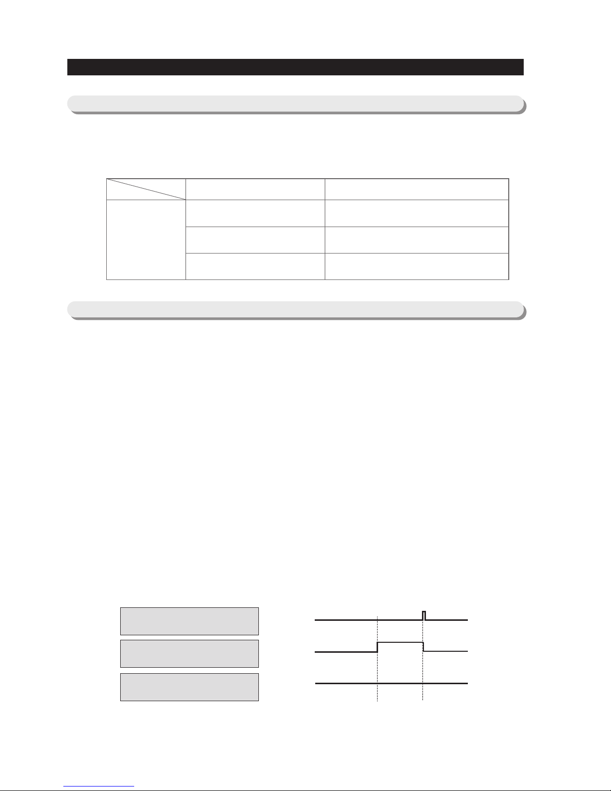
PRECAUTIONS(SAFETY WARNINGS)
Read all instructions before repairing the product, and follow to the instructions
in order to prevent danger or property damage.
CAUTION/WARNING SYMBOLS DISPLAYED
SYMBOLS
Indicates that a
danger of death
or serious injury
exists.
Indicates that a risk
of personal injury
or material damage
exists.
means “Forbidden”.
means “do not disassemble”.
means “do not touch”
means “Instructions that need to be
followed”
means “Ground to prevent Electric
shock”.
means “power cord should be
unplugged from the consent”
Pull the power plug out to
exchange the interior lamp
of the refrigerator.
●
It may cause electric shock.
Warning
Warning & Caution
Caution
Unplug
Use rated components for
the replacement.
●
Check for the correct model, rated
voltage, rated current, operating
temperature and so on.
Upon repair, make sure that the
wires such as harness are
bundled tightly.
●
Bundle wires tightly for them not to be
detached by an external force and not to get
wet.
Check if there is any trace indicating
water permeation.
●
If there is that kind of trace, change
the related components or do the
necessary treatment
such as taping
using the
insulating tape.
After repair, check the
appearance of the assembled
components.
●
IThey must look the same as they did
before disassembly.
Upon repair, remove completely dust or
other items form the housing areas,
harnesses, and check parts appearance.
●
Cleaning may prevent the possible fire by
tracking or short.
Rated
components

6
PRECAUTIONS(SAFETY WARNINGS)
❈
Please ler users know following warnings & cautions in detail.
Do not allow users to put glass
bottles or similar in the freezer.
●
Freezing the contents may cause .
Do not allow users to store narrow
and long bottles or foods in a small
multi-purpose room.
●
It may hurt you when the refrigerator door
is opened and closed resulting in stuff falling
down.
Do not allow users to store
pharmaceutical products, scientific
materials, etc., in the refrigerator.
●
Products which require temperature control
should not be stored in the refrigerator.
Do not allow users to store
articles on top of the product.
●
Opening or closing the door may cause
things to fall down, witch may cause injury.
Forbidden
Forbidden
Forbidden
Forbidden
Warning & Caution
Do not allow users to
disassemble, repair or alter.
●
It may cause fire or abnormal operation
leading to injury.
Do not
disassemble
Do not allow users to insert the
power plugs for many products
at the same time.
●
May cause abnormal generation of
heat or fire.
Forbidden
Do not allow users to bend the
power cord with excessive force or
do not allow the power
cord to get pinched by a heavy item.
●
May cause fire.
Do not allow users to install the
refrigerator in a wet place or a
place where water splashes.
●
Deterioration of the insulation of electric
parts may cause electric shock or fire.
Ensure grounding.
●
If grounding is not done, it will cause
breakdown and electric shock.
Ground

26
4. ALIGNMENT AND ADJUSTMENTS
4-1) TEST (FORCED OPERATION / FORCED DEFROST)
··············
27
4-2) RESTORATION OF OPERATION CONDITIONS FOR POWER FAILURE
···
28
4-3) ALARM
········································
28
4-4) EXHIBITION MODE
··································
28
4-5) SELF-DIAGNOSIS
···································
29
4-6) LOAD STATUS DISPLAY
·······························
31
4-7) OPTION SETTING
··································
32
4-8) OPTION TABLE
····································
34
27
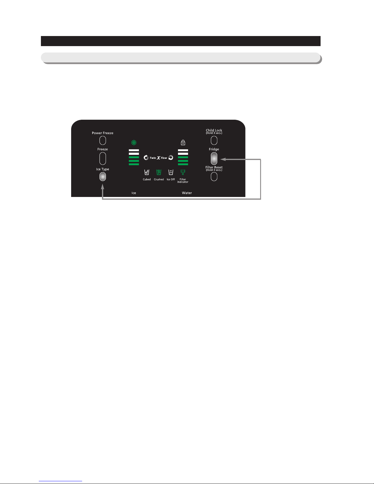
ALIGNMENT AND ADJUSTMENTS
●
When pressing Refrigerator temp set KEY and ICE TYPE KEY in PANEL PCB simultaneously for more than 8
sec. PANEL DISPLAY will go off and it moves onto TEST MODE. At this point, although Freezer/Refrigerator
temp set KEY, Power freezing KEY, and ICE TYPE KEY are pressed, it operates by TEST KEY.
● When pressing TEST KEY, Test function shall be changed in the order as Forced Operation ---> Forced
Freezer Defrost---> Cancellation(normal operation)---> Forced Operation. If functions are canceled during the
operation of TEST function, it is most desirable to turn off the power and turn it on again.
4-1) TEST (FORCED OPERATION / FORCED DEFROST)
Press for 8
seconds
1) Forced Operation
1-1) When pressing TEST KEY once in TEST MODE, Forced Operation shall be selected and with BEEP
sound, alarm will be operated.
1-2) If Forced Operation is selected, COMP. operates instantly without 5 min. delay in any Operation MODE. At
this point, if it is in Defrost, Defrost will be stopped instantly.
1-3) With the selection of Forced Operation, COMP. and Freezer FAN operate for 24 hr. continuously and
Refrigerator shall be regulated by set temp while Forced Operation continues until the completion of
forced operation or the conversion to other MODE (forced Freezer Defrost) or cancellation.
1-4) With the selection of Forced Operation, Freezer will be selected at “ MAX(-13 °F/ -25 °C) ”and Refrigerator
will be set at “ MID (35.6 °F/ 2 °C) ”automatically. However, although forced defrost or test cancellation are
selected after a minute while selecting forced operation, set temp will not change. (Maintaining “ MAX (-13
°F/ -25 °C) ” and “ MID(35.6 °F/ 2 °C) ” ) If forced defrost or test cancellation are selected in a minute while
selecting forced operation, set temp will go back to the previous set temp before “ MAX (-13 °F/ -25 °C) ”
and “ MID (35.6 °F/ 2 °C) ” .
1-5)
On the completion of Forced Operation (24 hr.), Freezer defrost will operate regardless of the previous state.
1-6) After the above items, it operates under the conditions of normal defrost by judging case by case.
1-7) If it is cancelled randomly during Forced Operation, (On changing into cancellation Mode), the time for
COMP. ON during forced operation shall be calculated in total and reflected in defrost cycle.
1-8) During Forced Operation, Power freezing doesn’t function and with the selection of function, LED
indication for the selected POWER function will be off after 10 sec.
2) Forced Defrost
2-1) When pressing TEST KET twice in TEST MODE, Freezer defrost will operate and BEEP sound alarm
shall be heard.
2-2) BEEP sound alarm shall operate until the completion of HEATING and pause.
2-3) With the selection of forced Freezer defrost, it will operate regardless of the point of normal Heater On and
complete defrost while comparing the temp of the point of HEATER OFF.
3) TEST Cancellation MODE
3-1) When converting DISPLAY PANEL into TEST MODE and pressing TEST button one more time during
Freeaer Defrost, Freezer Defrost will be cancelled and restored to normal operation. Also, if MAIN
POWER is turned on again after being turned off, all the TEST functions will be canceled.

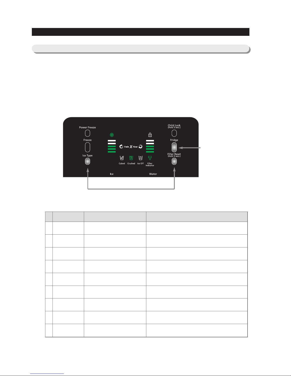
● When pressing Power Freeze and Freezer KEY on the front Display PANEL simultaneously for 3 seconds.
It will operate as Exhibition Mode with Ding Dong sound.
● Contents of operation in Exhibition Mode DISPLAY, FAN MOTOR, and DISPENSER will operate normally
except for Comp. and C-Fan.
● Exhibition Mode is not cleared even if power reset.
● To cancel Exhibition Mode, press same key (Power Freeze and Freezer KEY) for same time (3 secsonds)
● If the temperature of Freezer/ Fridge increases more than (149°F/65°C) in Exhibition Mode, it will restore to
normal operation mode.
4-4) EXHIBITION MODE
Press for 8
seconds
28
ALIGNMENT AND ADJUSTMENTS
1) Button TOUCH
1-1) When selecting each button in the CONTROL PANEL, the verification sound (Ding Dong) of input shall
be heard.
1-2) In the case of pressing more than two KEYS at the same time or pressing the wrong button, the sound
shall not be heard.
2) DOOR-OPEN
2-1) After passing 2 min. consecutively as Freezer/Refrigerator DOOR opened, SOUND alarm (Ding Dong)
shall be heard.
2-2) If the door is still open afterward, sound alarm will be circulated to SOUND (Ding Dong) generating
movement at the interval of a min.
2-3) Alarm stops when Freezer/Refrigerators are all closed.
1) In the case of instant power failure and initialization of PANEL DISPLAY, these can make customer’s NONSENSE CALL. To avoid this, if power is applied, it judges the temp of Freezer and operates as either
initialization or restoration of operation conditions.
2) With initial POWER ON, it judges the temp of Freezer and if it is below (+41°F/+5°C), it is judged as instant
power failure while operating and restoring the functions related to PANEL DISPLAY such as Power freezing,
CHILD LOCK and Freezer/Refrigerator settings.
3) With initial POWER ON, it judges the temp of Freezer and if it is above (+41°F/+5°C), it is judged as extended
power failure and PANEL DISPLAY will be initialized (Automatic setting at (-4°F/-20°C) for Freezer and
(37.4°F/3°C) for Refrigerator).
4-3) ALARM
4-2) RESTORATION OF OPERATION CONDITIONS FOR POWER FAILURE

29
4-5) SELF-DIAGNOSIS
Press for 8 seconds
ALIGNMENT AND ADJUSTMENTS
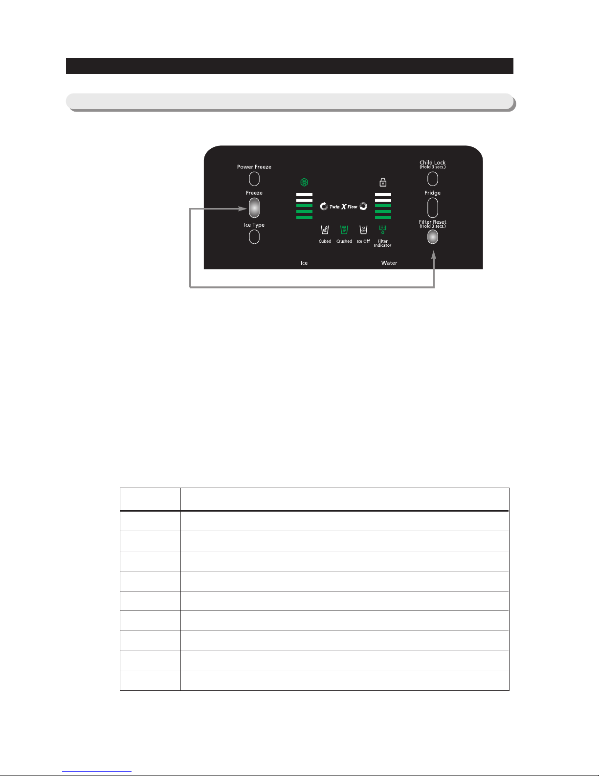
1) Self-diagnosis with initial POWER ON
1-1) With POWER ON, it shall diagnose the status of temp SENSOR in a minute in MICOM internally for itself.
1-2) If inferior sensor is found after self-diagnosis, corresponding DISPLAY LED will be all off at the interval of
0.5 sec. and there will be no sound with LED ON.
1-3) In the state that inferior sensor is found and DISPLAY ICON is off, it only recognizes self-diagnosis KEY
(Press Ice Type KEY + FILTER RESET KEY(LIGHT KEY) for 8 sec.) and normal temp control will be on
hold.
1-4) On self-diagnosis ERROR, if inferior sensor is fixed or if you press ICE TYPE KEY + FILTER RESET
KEY(LIGHT KEY) for 8 sec., it will be canceled automatically.
2) Self-diagnosis during normal operation
2-1) When pressing “ ICE TYPE ” and “ FILTER RESET(LIGHT) ” KEYS simultaneously for 6 sec. in normal
operation of the fridge, temp set DISPLAY will be All ON/OFF for 2 sec. at the interval of 0.5 sec. and
when pressing “ ICE TYPE ” and “ FILTER RESET(LIGHT) ” KEYS simultaneously for 8 sec. including
TOGGLE for 2 sec., self-diagnosis will be selected.
2-2) At this point, “ SOUND ”shall be heard and it operates self-diagnosis.
2-3) When self-diagnosis operates, entire LED will be OFF and only relevant LED with malfunction will be ON
/ OFF repeatedly signifying defects. (Refer to the below self-diagnosis CHECK LIST)
2-4) When an ERROR occurs, it will be indicated for 30 sec. and restored to the normal status regardless of
maintenance.
2-5) During self-diagnosis KEY input will not be recognized.

30
ALIGNMENT AND ADJUSTMENTS
NO Item DISPLAY LED Description How to Self-Diagnose
Refrigerator
SENSOR
1 Refrigerator "MID"
Fall out SENSOR HOUSING in
Refrigerator contanct failture, breakage of
wire, short-circuit, inferior Refrigerator
SENSOR and others.
Indicating a defect when the temp sensing
of Refrigerator SENOSR is above
(149°F/65 °C) and below (-58 °F/-50 °C).
The voltage should be within the range of
4.7V~0.6V between MAIN PCB CN30 #
8 and #9.
Peripheral temp
SENSOR
2 Refrigerator "MIN"
Fall out peripheral temp SENSOR
HOUSING , contact failure, breakage of
wire, short-circuit, inferior peripheral
sensor and others.
Indicating a defect when the temp sensing
of peripheral temp SENOSR is above
(149°F/65 °C) and below (-58 °F/-50 °C).
The voltage should be within the range of
4.7V~0.6V between MAIN PCB CN31 #
1 and #4.
Freezer SENSOR3 Freezer "MAX"
Fall out SENSOR HOUSING in Freezer,
contact failure, breakage of wire, shortcircuit, inferior Freezer SENSOR and
others.
Indicating a defect when the temp sensing
of Freezer SENOSR is above
(149°F/65°C) and below (-58 °F/-50 °C).
The voltage should be within the range of
4.7V~0.6V between MAIN PCB CN30 #
4 and #5.
Freezer Defrost
SENSOR
4 Freezer "MID"
Fall out Deforst - SENSOR HOUSING in
the evaporator of Freezer, contact facilure,
breakge of wire, short-circuit, inferior
sensor and others.Indicating a defect when
the temp sensing of Freezer Defrost
SENOSR is above (149 °F/65 °C) and
below (-58 °F/-50 °C).
The voltage should be within the range of
4.7V~0.6V between MAIN PCB CN30 #
4 and #6.
Freezer Defrost
ERROR
5 Freezer "MIN"
Fall out Freezer Heater Housing, contact
failture, breakage of wire, short circuit,
inferior Freezer Heater, or inferior Defrost
temp fuse and etc.
On Freezer Defrost 90 min. automatic
completion
I/M Function
ERROR
6 ICE OFF
Ejection restoration failure more than 3
times.
Push the test buttono nI/
MAss'y and It should work.
I/M SENSOR
ERROR
7 Cubed LED
Fall out I/M SENSOR HOUSING, contact
failure,brekage of wire,short-circuit, inferior
I/M-SENSOR and etc.
The voltage should be within the range of
4.7V~0.6V between MAIN PCB CN90 #
3 and #4.
DAMPER HEATER8 Refrigerator "MAX"
Damper Heater Slipped Away, Poor
Contact, Wire Breakage, Short Circuit,
Defective Damper Heater
Indicates error when the Damper Heater is
detected as open (Only for Energy Star)
F-FAN RESTRAINT9
Crushed Ice
F-Fan Restraintor Defect
Upon detection of F-Fan restraint
(Only for Energy Star)
C-FAN RESTRAINT10
Crushed Ice
(Blinking)
C-Fan Restraintor Defect
Upon detection of C-Fan restraint
(Only for Energy Star)
Details of self-diagnosis lighting by
31
1)
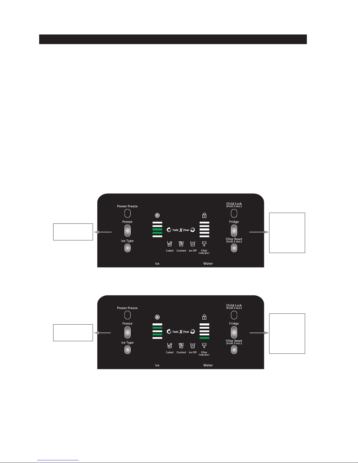
When pressing “ICE TYPE” and “FILTER RESET(LIGHT)” KEYS simultaneously for 6 sec. in normal
operation, the indicators of temp set in Freezer/Refrigerator will all ON/OFF for 2 sec. at the interval of 0.5 sec.
At this point, when pressing Temp Set Key in Refrigerator while canceling “ICE TYPE” and “FILTER
RESET(LIGHT)” KEYS, it operates load status display.
2) Load status display will show the load in operation REAL TIME.
However, it is not related to real status of operation of load and it only shows the directed status of the load
operation command from MICOM.
3) Only corresponding ICON for the load in operation will be ON/OFF repeatedly and turned off.
4) Load status display will continue for 30 sec. and it will restore to the normal state.
ALIGNMENT AND ADJUSTMENTS
4-6) LOAD STATUS DISPLAY
② Press after ①
NO ITEMS DISPLAY LED PROBLEM
01
02
03
04
05
06
07
08
09
Damper
Condition for
over load
Condition for
low temp
COMP
Freezer Defrost
Heater
Freezer FAN
Exhibition Mode
Dispenser Heater
Damper Heater
Refrigerator "MIN" (1’st)
Refrigerator "MID" (3’rd)
Refrigerator "MAX" (5’th)
Freezer "MIN" (1’st)
Freezer "MID" (3’rd)
Freezer "MAX" (5’th)
ICE OFF
CUBE LED
CRUSH LED
LED ON whenDamper is open
LED ON when Ambient temp is over (95°F/35 °C)
LED ON when ambient temp is lower than (62.6 °F/17 °C)
Relevant LED ON whenCOMP operates
LED ON when Freezer Defrost Heater operates
Relevant LED ON when Freezer-FAN HIGH operates
LED ON in Display mode
Relevant LED ON when Dispenser Heater gets ON
Relevant LED ON when Damper Heater gets ON
Details by LED ON locations indicating load status
① Press for 6 seconds
32
OPERATING INSTRUCTIONS & INSTALLATION
● When the F-Room Temp Setting button and the Filter Reset button or the Lighting button are pressed for 12
seconds continuously,the display will be converted to the option setting mode.
4-7) OPTION SETTING
Press for 12
seconds
1) For example, if you want to shift the Refrigerator standard temp by (26.6°F/-3 °C), proceed the following.
It is to shift the standard temperature.The F-Room standard temp is (-4°F/-20 °C)(MID).When it is shifted
(26.6°F/-3 °C) by using the option,the standard temp will be set to (-9.4°F/-23 °C) when the temp option is
changed, it will be controlled to (-9.4°F/-23 °C) internally even though it is set to MID on the display panel..So,
shifting the standard temperature by (26.6°F/-3 °C) means that it is controlled by (26.6 °F/-3 °C) increase than
the temp set on the display panel.
1-1) As shown in the draft,press the Freezer button and the FILTER RESET BUTTON OR LIGHTING
BUTTON for 12 seconds simultaneously.
- Except the Freezer &the Fridge LEDs, all LEDs will be turned off.
1-2) When it is changed to the option mode, all of the OPTION CATEGORY (I1~I5)and,the OPTION
SETTING (V1~V4) will display "0"(ALL OFF).
(The option should be set "0" for shipment, but this standard set value could be changed and shipped for
quality improvement during mass production.)
- The LED arrangements of the OPTION CATEGORY and the OPTION SETTING for different specs are
as follows.
(For the Value Spec,the Dispenser LED is used due to the insufficient number of panel LEDs.)
I1
I2
I3
I4
I5
V1
V2
V3
V4
FRIDGE MIN
FRIDGE MID-M IN
FRIDGE MID
FRIDGE MID-M AX
FRIDGE MAX
FREEZER MIN
FREEZER MID-MIN
FREEZER MID
FREEZER MID-MAX
RS2630A**
V4
V3
V2
V1
I5
I4
I3
I2
I1
Item+
Item –
Value+
Value–
V4
V3
V2
V1
I5
I4
I3
I2
I1
Item+
Item –
Value+
Value–
Item+
Item –
Value+
Value–
Item+
Item –
Value+
Value–
33
OPERATING INSTRUCTIONS & INSTALLATION
1-3) If you set "6"as shown in the Freezer option table below after setting "0"to the OPTION CATEGORY,the
Refrigerator standard temp will be lowered by -5.4°F(Refer to the Refrigerator Temp Option Table)
:In 20 seconds after completion of adjustment,the MICOM will store the set value to the EEPROM and
it will revert to the normal display and the option setting mode will be cancelled.
1-4)To increase/decrease the OPTION CATE., press the Fridge button and the Filter Reset(or Lighting
button)respectively and to increase/decrease the OPTION SET VALUE, press the Freezer button and the
Ice Type button respectively.
1-5)The option function will be set in the EEPROM before shipment,so do not change the setting except
special cases.For the option function, the setting will be completed when it is reverted to the normal
display in 20 seconds. So, do not turn off the power before it is reverted to the normal display.
1-6) Make sure to set the OPTION CATE.(I1~I5)first and then set the OPTION SETTING(V1~V4).
Note) Basically,refrigerators are shipped with option data cleared.
i.e.products are shipped with set values all "0".But,for quality improvements during MP,refrigerators could
be produced with set values changed.So,make sure to check the Quality Information.
APP .EX) TO INCREASE REFRIGERATOR STANDARD TEMP BY (2.7°F/1.5°C)
APP .EX)TO DECREASE FREEZER STANDARD TEMP BY (-5.4°F/-3°C).
Option Setting
(6:(-5.4°F/-3°C))
Option
Category.
(0 : Freezer
Standard
Temp)
Option Setting
(10: 2.7°F/1.5°C)
Option
Category.
(1: Refrigerator
Standard
Temp)

34
OPERATING INSTRUCTIONS & INSTALLATION
Note) With the Freezer button and the Lighting button, additional options can be set.
But, those are relevant not to the A/S but to the ref.control function. So, those options are skipped.
(Do not change any other options except the above options.)
1) FREEZER TEMP SHIFT TABLE(○: RELEVANT LED OFF, ●: RELEVANT LED ON)
2) REFRIGERATOR TEMP SHIFT TABLE(○: RELEVANT LED OFF, ●: RELEVANT LED ON)
4-8) OPTION TABLE
SET ITEM
MODEL
SET VALUE
Option Value
COMMON
DISPLAY
Option Item
VALUE I1 I2 I3 I4 I5
0
○○○ ○○
VALUE V1 V2 V3 V4
0
1
2
3
4
5
6
7
0°F /0 °C
-0.9 °F/-0.5 °C
-1.8 °F/-1.0 °C
-2.7 °F/-1.5 °C
-3.6 °F/-2.0 °C
-4.5 °F/-2.5 °C
-5.4 °F/-3.0 °C
-6.3 °F/-3.5 °C
○
●
○
●
○
●
○
●
○
○
●
●
○
○
●
●
○
○
○
○
●
●
●
●
○
○
○
○
○
○
○
○
8
9
10
11
12
13
14
15
0.9°F/+0.5 °C
1.8 °F/+1.0 °C
2.7 °F/+1.5 °C
3.6 °F/+2.0 °C
4.5 °F/+2.5 °C
5.4 °F/+3.0 °C
6.3 °F/+3.5 °C
7.2 °F/+4.0 °C
○
●
○
●
○
●
○
●
○
○
●
●
○
○
●
●
○
○
○
○
●
●
●
●
●
●
●
●
●
●
●
●
SET VALUE
Option Value
COMMON
VALUE V1 V2 V3 V4
Freezer TEMP SHIFT
AD -PJT
SET ITEM
MODEL
SET VALUE
Option Value
COMMON
DISPLAY
Option Item
VALUE I1 I2 I3 I4 I5
1
●○○ ○○
VALUE V1 V2 V3 V4
0
1
2
3
4
5
6
7
0°F /0 °C
-0.9 °F/-0.5 °C
-1.8 °F/-1.0 °C
-2.7 °F/-1.5 °C
-3.6 °F/-2.0 °C
-4.5 °F/-2.5 °C
-5.4 °F/-3.0 °C
-6.3 °F/-3.5 °C
○
●
○
●
○
●
○
●
○
○
●
●
○
○
●
●
○
○
○
○
●
●
●
●
○
○
○
○
○
○
○
○
8
9
10
11
12
13
14
15
0.9°F/+0.5 °C
1.8 °F/+1.0 °C
2.7 °F/+1.5 °C
3.6 °F/+2.0 °C
4.5 °F/+2.5 °C
5.4 °F/+3.0 °C
6.3 °F/+3.5 °C
7.2 °F/+4.0 °C
○
●
○
●
○
●
○
●
○
○
●
●
○
○
●
●
○
○
○
○
●
●
●
●
●
●
●
●
●
●
●
●
SET VALUE
Option Value
COMMON
VALUE V1 V2 V3 V4
Refrigerator TEMP SHIFT
AD -PJT

16
3. OPERATING INSTRUCTIONS & INSTALLATION
3-1) DISPLAY DESIGN ···································17
3-2) TEMP CONTROL
···································
17
3-3) POWER FREEZING
··································
18
3-4) CHILD LOCK
······································
18
3-5) ICE DISPENSER & WATER DISPENSER
·····················
19
3-6) FAN MOTOR DELAY (COMPRESSOR ROOM)
··················
20
3-7) ICE MAKER
······································
20
3-8) DEFROST
·······································
24
3-9) INSTALLATION
·····································
25

17
OPERATING INSTRUCTIONS & INSTALLATION
3-1) DISPLAY DESIGN
1) Freezer Temp Setting
1-1) With the initial power on, Freezer will be set at MID (-4°F/-20°C) and Refrigerator will be set at MID
(37°F/3°C) automatically. At this time, the number of LEDs (1 ~ 5) lighting up on the display panel means
intensity (MIN ~ MAX) of room control temperature (6.8 ~ -13°F/-14 ~ -25 °C) and as the intensity gets
increased, the number of LEDs increases and the set temperature become lowered.
1-2) Freezer Temp can be set from (6.8°F/-14°C)(MIN) to (-13°F/-25°C)(MAX) with Freezer temp setting button.
2) Refrigerator Temp Setting
2-1) Refrigerator Temp can be set from (44.6°F/7°C)(MIN) to (33.8°F/1°C)(MAX) with Refrigerator temp setting
button.
2-2) Refrigerator set temp varies slightly from actual temperature according to the user’s way of storing food
and peripheral temp. (If food is stored too close to Refrigerator Temp Sensor, it can block air circulation
resulting in weak or over cooling. So, be careful not to block it.)
Note) When power is out due to an instant power failure or the problems in an electric circuit and restored
again, the ref checks Refrigerator Temp. At this time, When Freezer Temp is lower than (41°F/5°C) ,
Refrigerator considers it as an instant power failure and restores the previous temp and functions stored
in EEPROM for use.
3-2) TEMP CONTROL

3-4) CHILD LOCK
18
3-3) POWER FREEZING
OPERATING INSTRUCTIONS & INSTALLATION
● It is selected with Power Freeze Button.
● Each time you press Power Freeze Button, it repeats SELECT ↔ CANCEL (Relevant ICON ON/OFF).
● When Power Freeze is selected, the temp settings of Refrigerator/Freezer does not change.
● When Power Freeze is selected, it is possible to change the temp settings of Refrigerator/Freezer.
1) POWER FREEZING
1-1) When Power Freeze is selected by pressing Power Freeze Button, ICON gets on immediately but Power
Freeze starts its operation in 10 sec. However, when Power Freeze Button is reselected during Power
Freeze, ICON gets off and operation ends with the selection of Power Freezing.
1-2) When Power Freeze is selected, Comp & Freezer-Fan operates continuously for 2hr. and 30min.
1-3) During Power Freeze, Refrigerator continues its previous operation.
1-4) After turning off of Power Freeze, Power Freeze lamp goes off automatically and Freezer operates
according to the set temp.
1-5) When it becomes conditions for Defrost during Power Freeze, Defrost gets delayed and it starts operating
upon completion of Power Freeze.
When Power Freeze is selected during Defrost, Power Freeze ICON lights up immediately. But, Comp and
Freezer-Fan gets on upon completion of Defrost. (But, the initial 4hr. Defrost comes before Power Freeze)
● When Child Lock Button on the front panel is pressed for a certain period (3sec.), Child Lock LED gets on
and all other buttons on the front panel except for Child Lock Button do not operate. Also, Ice/Water
Dispensers do not work.
(Display & all Ref functions will maintain the conditions before Child Lock gets on)
● In the above status, when Child Lock Button is pressed for a certain period (3sec.) again, Child Lock LED
gets off and all other buttons on the frontal panel start operating and Ice/Water Dispensers work.
● This function is developed to prevent random controlling by children. It can be used according to the user’s
need and it needs to be well informed and reminded in advance because it could make Non----sense Calls by
customers.

19
OPERATING INSTRUCTIONS & INSTALLATION
1) CUBE/CRUSHED/ICE OFF SELECTION
1-1) Upon the initial Power On, when F-Room Temp is above (41°F/5°C), CUBE LED on the Display lights up
and the other LEDs remains OFF. But, when F-Room Temp is lower than (41°F/5°C), it restores the ice
selection before the POWER OFF and displays it on the panel.
1-2) It is selected in the order of CUBE → CRUSHED → ICE OFF repeatedly by ICE TYPE key.
1-3) When operating Ice Dispenser Lever with CUBE or ICE OFF selected, it sends out ice cubes.
1-4) When pressing Ice Dispenser Lever with CRUSHED selected, it sends out crushed ice.
1-5) When ICE OFF is selected, ICE-MAKER does not make ice.
Note) When taking out ice with ICE OFF selected, only ice lefted in the storing box is extracted.
2) FILTER RESET
2-1) When FILTER INDICATOR LED on the front Panel becomes orange or red, Filter should be changed.
2-2) - When FILTER RESET button is pressed for a certain period (3sec) after changing Filter, FILTER
INDICATOR LED becomes green with “ Ding Dong ” sound. (When FILTER RESET is pressed, water
count is reset to 0)
- When the filter is replaced,reset the indicator by pressing the FILTER RESET button for 3 second at the
same time.
2-3) After Filter reset, when 270 Gallon water is used (including water used in making ice), FILTER
INDICATOR LED becomes orange , and when 300 Gallon water is used, FILTER INDICATOR LED
becomes red.
2-4) When the water filter is not needed due to the use of purified water or other reasons, the Filter Indicator
can be turned off. When pressing the Filter Reset Button for 5 seconds continuously, the Filter Indicator will
be off with a "Ding Dong" sound. (At this time, when 3 sec has passed, the filter will be reset with a "Ding
Dong" sound and when 5 sec has passed, the Filter Indicator will be off.)
2-5) When the Freezer temperature is higher than 41 °F upon the initial power on, the Filter Indicator will be
turned on. And, when it is lower than 41 °F, it will display the previous setting (before the power off).
3-5) ICE DISPENSER & WATER DISPENSER
20
● Among the functions depending on Peripheral Temp, Comp Cooling Fan (Comp Room Fan) is controlled
according to Peripheral Temp as follows.
Therefore, make sure to check the contents to refer to during A/S because Cooling Fan can operate or not
according to conditions during Comp operation.
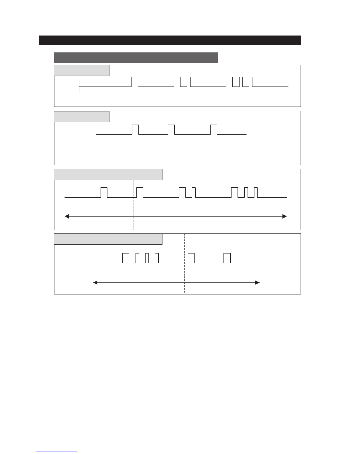
1) Initialization (Restoration to the initial horizontal status)
When the Ice Maker is initialized by Power On or the Ice Error Mode, the Ice Tray gets leveled again by
rotating the Eject Motor regardless of the horizontal state of the Ice Tray.
1-1) Conditions for Initialization
- After pending time (5sec.) for activation of each MICOM port with the initial Power On or the Power
On after Power Failure.
- When an error occurs due to full icing or the restraint of the Eject Motor, it starts initialization in 24 hours
upon full icing and in an hour upon the counter-rotation error of the Eject Motor.
1-2) Movement for Initialization
- Satisfy the initial horizontal status by counter-rotating the Eject Motor.
- When the voltage of the Motor Voltage Sensor becomes above 0.55V during counter-rotation of the
Eject Motor, the counter-rotation stops.
- When it is not detected that the Motor Voltage Sensor becomes more than 0.55V for a minute after
the counter-rotation, it is considered as an error and initialization gets started again in an hour.
- It stands by for the initial Ejection for a cycle (2 hours) after completion of initializing movement by Power
On and it stands by for normal Ejection after completion of initializing movement by error.
- After the Ejection Stand-by time has passed, check the temp of the Ice Tray and if the temp reaches
to the Ejection temp, it carries out the Ejection.
1-3) Initializing Movement Timing Chart
OPERATING INSTRUCTIONS & INSTALLATION
3-6) FAN MOTOR DELAY (COMPRESSOR ROOM)
3-7) ICE MAKER
Load operation state
Range of Ambient Temp
Comp Room
DELAY
Above (64.4°F/18°C)
Below (53.6°F/12°C)
With COMP.ON, Comp Room Fan will be
on immediately
After 5 min. from COMP.ON, Comp
Room Fan will be on
Regardless of COMP., Comp Room
Fan will be off
Voltage of Ice
Ejection Motor
Ice Ejection Motor
(Counter clockwise)
Ice Ejection Motor
(clockwise)
Initialization starts
0.55V ↑
0.5V ↓
ON
OFF
ON
OFF
Between (55.4°F/13°C)
and (62.6°F/17°C)

21
OPERATING INSTRUCTIONS & INSTALLATION
2) Water Supply
It is the movement to supply water on the ICE-TRAY by using the SOLENOID VALVE after the completion
of the ejection (Ejection after the completion of the normal ice making or that by the test movement)
Considering cases with low hydraulic pressure, when it is recognized as No Water Supply, the Water Supply
will be attempted for 4 times.
2-1) Specifications for water supply
- After the completion of the normal ejection and the opening of the water supply valve, water is supplied for
the previously set OPTION time (Set by the DIODE in PCB and normally for 5 sec) and the water supply
valve gets off.
- Water is supplied regardless of the F/R-DOOR OPEN
- While supplying water, the ICE TEST S/W doesn’t work.
- In one min. and 30 sec. after the completion of water supply, Water Supply/ No Water Supply will be
judged.
- Under the condition of additional water supply due to No Water Supply, the additional water supplying time
is 1.5 sec, 1 sec, and 2 sec.
- When judging water supply after the trial of water supply within the number of previous water supply,
complete water supply. In this case, the Ejection Stand-By Time is 58(65) min.
- To prevent the additional water supply by the judgment of No Water Supply due to the ice cube on the tray
cube which the ice maker sensor of the ICE-TRAY is, quit the water supplying movement for one time
when it is judged as No Water Supply after trying to supply water as many as the number of the previous
water supplying. After POWER ON, the number of the previous water supplying will be considered as
once for the first water supplying and when No Water Supply is judged after the initial water supplying, quit
the water supply movement. If the number of the previous water supply is three times, supply water for 3
times, and when judged as No Water Supply, quit the water supplying movement. In this case, the
Ejection Stand-By Time is 70~110 min.
- When judged as No Water Supply in the previous water supply, supply water for 5 sec, 1.5sec, 1sec,and 2
sec for 4 times.
- According to conditions, the Ejection Stand-by Time is as follows.
2-2) Judgment of Water Supply by the ICE-TRAY Temp sensor
- In one and a half min after the completion of the water supply, judge either the Water Supply or the No
Water Supply by comparing the temp change of the ice maker sensor on the ICE TRAY.
- In the case that the temp of the ICE-TRAY ice maker sensor in one and a half min. after the completion of
the water supply is 2 degrees (5 COUNT) higher than that during the water supply movement, it is judged
as the Water Supply and when the temp increases or decreases less than 2 degrees, it is considered as
the No Water Supply.
2-3) Specifications of water supply movement upon pressing the Ice Test S/W
- Supply water for once regardless of the previous water supply.
- The Ejection Stand-by Time after the completion of water supply is the same as that after the completion
of the previous water supply movement regardless of the Water Supply/ No Water Supply recognition.
- Do not change the number of the previous Water Supply. That is, if the number of Water Supply before
pressing the ICE TEST S/W is 3 times, that of the previous Water supply after the completion of the Water
Supply by pressing the ICE TEST S/W is also 3 times.
Detection of No Water Supply
Detection of Water Supply
Number of
water supply
Lower than
(62.6°F/17°C)
65 (58+7) min
58 min
Higher than (64.4°F/18°C)
58 min
58 min
Lower than
(62.6°F/17°C)
110 min
70 min
Higher than (64.4°F/18°C)
95 min
70 min
1
2~4
22
OPERATING INSTRUCTIONS & INSTALLATION
3) Ice Making
It is until the water in the ICE-TRAY after the completion of Water Supply gets frozen completely and the ice
making movement is completed by the temp of the ice making temp pickup part using the ice maker sensor
(THERMISTOR).
3-1) After water is supplied to the ICE-TRAY, check the temp pickup part of the ice maker sensor after the
Ejection Stand-By Time for 58(58~110) min. (For the No Water Supply, 90 min) and judge whether the temp
of the ice maker sensor is below (1.4°F/-17°C).
3-2) If the ice maker sensor maintains the temp below (1.4°F/-17°C) for 5 min. It is judged that ice making is
completed. However, do not check the ice maker sensor within the Ejection Stand-By Time from the point of
Water Supply. (Protection function when the sensor is faulty or the cold air leaks.)
3-3) Stand-by for 1 CYCLE: After the completion of the initialization by POWER ON, it stands by for 1 CYCLE
(2hr.) and operates the Ejection although the temp condition of the ice maker sensor is satisfied.
3-4) As long as the temp of the temp sensing part maintains below (1.4°F/-17°C) for more than 5 min, the
Ejection will be carried out. If the temp fluctuates below (1.4°F/-17°C) above (1.4°F/-17°C), the Ejection will
be carried out after 5 min. at the temp below (1.4°F/-17°C) while counting the Stand-by Time entering the
temp below (1.4°F/-17°C).
Low water pressure
5s 5s 1.5s 5s 1.5s 1s
Assumption of the ambient temp of higher than 64.4 °F/ 18 °C
Power On
No Water Supply No Water Supply No Water Supply
Initial 2hr standby 95+(5)min 70+(5)min 70+(5)min
High water pressure
5s 5s 5s
Water Supply No Water Supply Water Supply
58+(5)min 95+(5)min 58+(5)min
High water pressure → Low water pressure
High water pressure Low water pressure
when the Ice cube on
the tray cube which the
sensor is attached is
not removed.
When the ice cube on
the tray cube which the
sensor is attached is
removed.
5s 5s 5s 1.5s 5s 1.5s 1s
Water Supply Water SupplyNo Water Supply No Water Supply
58+(5)min 58+(5)min95+(5)min 70+(5)min
Low water pressure → High water pressure
High water pressureLow water pressure
5s 1.5s 1s 2s 5s 5s
Water Supply Water Supply Water Supply
58+(5)min 58+(5)min 58+(5)min

23
OPERATING INSTRUCTIONS & INSTALLATION
4) Ice Ejection
It is the movement to separate the ice cubes from the ICE-TRAY after the completion of ice making, which is
conducted by the following steps. Check the changes in status and time for the horizontal S/W (if it is used)
and the ice level check S/W in parallel and then operate Ejection. At this point, the regular rotational direction
of the motors is clockwise (CW) and the reverse rotational direction of that is counter clockwise (CCW).
The Ice Ejection is carried out twice, which is to separate all the ice cubes from the ICE-TRAY.
4-1) Detailed movements by step during the Ejection.
- 1
st
step: Ejection temp checking step
Check whether the temp of the temp sensing part is below (1.4°F/-17°C) and whether the Ejection StandBy Time after Water Supply has passed. At this point, when the F-Defrost goes into operation during the
Ejection Standby, the Ejection Standby Time will be reset. Then, check that 58~110 min. has passed by
recounting from the beginning after the completion of the Defrost. If the temp of temp sensing part of ice
making become below (1.4°F/-17°C) and maintain it for 5 min, carry on the next step.
- 2
nd
step: Filled up ice container checking step
To check the ice level of the ice container, CHECK the ON/OFF (Low/High) of the ice level S/W If the ice
level S/W is ON (Low), it means that the ice container is full and the Ejection stands by. And when the ice
level S/W is turned OFF and 40 min. has passed, the Ejection will be carried out.
- 3
rd
step: ICE TRAY overturning step (clockwise)
It is the movement to turn over the TRAY to separate the ice cubes from the TRAY by rotating the Ejection
motor clockwise for a certain time period. At this point, raise the guide ice to prevent the ice cubes from
contacting the guide ice. Carry out the clockwise rotation for a minute from the start of the clockwise
rotation or until the horizontal S/W is ON (Low) after 5 sec from the beginning of the third step when using
horizontal S/W. If the door of the F-Room is open, stop the clockwise rotation and start the rotation after
the door is closed. During the temporary pause, the clockwise rotation will not be counted.
- 4
th
step: Ice separating step (Standby for 2 sec. at the maximum twist point )
It is the movement to twist the tray again in the reversed state to separate the ice cubes from the tray
completely and the tray receives torsion because the ICE-TRAY is stopped by the STOPPER. The ice
cubes are separated by this strength and the tray stands by for 2 sec. at the maximum twist point for
complete separation.
- 5
th
step: Reverting to horizontal level step (counter clockwise)
Rotate the Ejection motor in reverse to revert the ICE-TRAY to the horizontal level. When using the
horizontal S/W, reverse rotation begins.
When the horizontal S/W is ON (Low) after 5 sec from the beginning of the reverse rotation or the voltage
of the voltage sensing part of the motor is above 0.55V, the rotation will be stopped. At this point, the
raised guide ice becomes lowered again and touches on the highest point of the stored ice for checking
the ice level.
- 6
th
step: Motor initializing step (clockwise)
After a sec. upon the completion of the 5
th
step, the Ejection motor rotates clockwise for 2ms to release the
stress of the gear as well as to protect it.
4-2) Errors and handling methods during the ejection
- If the conditions of the completion for the reverse rotation are not satisfied in a min. after applying the
counter rotation during the execution of the 5 steps of the detailed ejection movement, it is considered as
an ERROR and stops the motor.
- If it is judged as an abnormal state, facilitate the initialization in an hour.
If the ejection error occurs 3 times consecutively, it is sensed as ERROR (ICE ERROR) and when
selecting the self diagnosis, it turns on the corresponding LED.
- If the ejection operates normally, the ERROR value of the existing ice making function will be deleted.

24
OPERATING INSTRUCTIONS & INSTALLATION
4-3) Ejection Movement TIMING CHART
5) Ice Test
It is necessary for the forced operation for the purpose of the operation test, A/S, and cleaning, and when
pressing the ICE TEST S/W for a certain time period (more than 1.5 sec.), it goes into operation.
5-1) The TEST button will not be selected during the Water Supply or the Ejection. Press it again with the
Water Supply or the Ejection completed to run the Test function. Standby for maximum 5 min. when Water
Supply operates.
5-2) When the TEST button is selected, the ejection will be carried out by running the eject motor regardless of
the elapsed time (58~110 min.) after the Water Supply and the temp of the ice making. And after this, the
tray will be reverted to the horizontal level and the ICE TRAY will be supplied with water.
5-3) It operates normally regardless of the Freezer/Refrigerator DOOR OPEN (No temporary pause functions
by the DOOR OPEN)
5-4) Other functions are the same as the movements of the Ejection and the Water Supply.
5-5) When ERROR occurs more than 3 times with the normal function and the ice making stops, the ICE TEST
shall operate. At this point, if the normal Ejection and Water Supply are operated by the TEST S/W, there
would be “Ding Dong” sound for once before the Water Supply and the third ERROR MODE will be
cancelled executing the normal ice making.
1) Freezer Defrost shall be determined by COMP ON total hour.
2) On the initial POWER ON, Defrost in Freezer will be operated after COMP ON total hour of 4 hr.
3) Defrost cycle changes automatically depending on the conditians
MIN 6 hr, to MAX“11” hr
4) The judgment of defrost cycle shall be determined by peripheral temp, No. of DOOR OPEN in
Freezer/Refrigerator, and the time for DOOR OPEN in Freezer/Refrigerator.
5) Point of Defrost HEATER OFF is (59 °F/15 °C) by the temp value of Freezer Defrost SENSOR.
● If F Defrost HEATER doesn’t reach to the point of Defrost OFF in 70 min., turn off forcibly and complete
Freezer-Defrost. ( Prevention of inferior HEATER OPEN or inferior Refrigerator Defrost Sensor )
Ice Level S/W
Horizontal S/W
Eject Motor rotates
clockwise
Eject Motor rotates
counter clockwise
ON
OFF
ON
OFF
ON
OFF
ON
OFF
Max TRAY twist Standby(2sec)
Restorating to
horizontal status
Completion
horizontal status
3-8) DEFROST
Initial
horizontal status
Ejecting

3-9) INSTALLATION
25
OPERATING INSTRUCTIONS & INSTALLATION
1) To protect refrigerator in movement
Use padded hand truck as shown. If entrance width is less than 39〃, remove doors prior to
installation and reattach doors according to procedure below.
2) Remove all protective tape and pad in refrigerators.
Connect water lines and power cord. Adjust the clearance between the doors.
3) Set the temperature control to the temperature and wait for an hour.
The refrigerator should get slightly chilled and the motor runs smoothly.
4) Once the refrigerator temperature is sufficiently low
You can store food in the refrigerator. After starting the refrigerator, it takes a few hours to
reach the appropriate temperature.

7
2. PRODUCT SPECIFICATIONS
2-1) Introduction of main function ····························· 8
2-2) Comparison of Design Change
···························· 9
2-3) Model Specification &Comparison Chart
·····················
10
2-4) Model Specification
··································
11
2-5) Electric Parts Specification
······························
12
2-6) Dimensions (Inch)
···································
14
2-7) Optional Material Specifications
···························
15

8
PRODUCT SPECIFICATIONS
●●
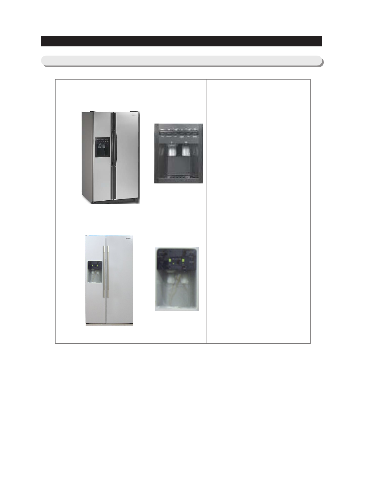
A newly developed SAMSUNG side by side refrigerator in 2006 has the following
characteristics.
Twin X AirFlow
·Cool air circulates through side vents on every shelf level. This
provides even distribution of cooling inside cabinets to keep your
food fresh longer.
Xtra Space
TM
·Vertical room next to the ice maker in the freezer provides space
for pizza etc.
Door Alarm
·Beep sound reminds you the door is open.
Vegetable Crisper
·Optimized humidity control keeps vegetables & fruits fresh.
2-1) Introduction of main function
2-2) Comparison of Design Change
PRODUCT SPECIFICATIONS
ITEM
BASIC MODEL(RS2630**)NEW MODEL(RS2530B**)
Appearance Design Feature
• Dispenser & Display Design :
Projecting control type
• Compartment Lighting : 30W
• Handle Design : A-Top LongBar (plastic)
• Freezer Compartment Basket
Type : Wire Basket
• Flat door plate
• Cover Hinge Type : Exposed
type
• New Design Dispenser
(Display) : Flat control type
• Compartment Lighting : 40W
• New Handle Design : Al oval
half bar
• Freezer Compartment Basket
Type : Plastic Box
• Contour door plate
• Cover Hinge Type : Hidden
type
9

10
2-3) Model Specification &Comparison Chart
PRODUCT SPECIFICATIONS

11
2-4) Model Specification
PRODUCT SPECIFICATIONS
Indirect Cooling Method Refrigerator
R-134a
175g
35.9"
X 34.8"X 70
"
NNeett ddiimmeennssiioonn((WW××DD××HH))
Rated Voltage and Frequency
Rated Input
Electric Heater Rated Power Consumption
Refrigerator Type
Refrigerant
Refrigerant Input Amount
Product Weight
Item
Specification
Net Capacity
Total
Fridge
Freezer
MMooddeell
24.8 Cu.Ft
15.5 Cu.Ft
9.3 Cu.Ft
before packing : 291(Ib)
after packing : 326(Ib)
115V / 60㎐
3.9A
310W
Dispenser without beverage station
RS2530B**
Item
Model
Specification
RS2530B**
MK183CL2U/E07
R.S.C.R
FREOL α- 10 (ESTER)
SPLIT FIN TYPE
Forced and natural convection type
Molecular sieve XH-9
0.85×3300mm
R-134a
ON(℃) OFF(℃)
22.5℃ 25.5℃
18.5℃ 21.5℃
12.5℃ 15.5℃
ON(℃) OFF(℃)
-0.5℃ 2.5℃
1.5℃ 4.5℃
5.5℃ 8.5℃
4 hr ± 10 min
17hr (varies according to conditions of used)
7 ± 1 min
THERMISTOR (502AT)
5.0㏀ at 25℃
60℃ OFF / 40℃ ON(140℉ OFF / 104℉ ON)
Freezer Components
Room Temperature Sensor Components
Defrost Related
Components
Freezer
Refrigerator
Defrost Cycle
Defrost
Cycle
Model
SPEC
F Defrost-
Sensor
Bimetal
Operating temperature
First Defrost Cycle (Concurrent defrost of F and R)
Defrost Cycle(FRE)
Pause time
Condenser
Dryer
Refrigerant
Capillary tube
THERMISTOR
(F-SENSOR)
502AT
Temperature Selection
24℃
20℃
14℃
1℃
3℃
7℃
COLD
NORMAL
WARM
COLD
NORMAL
WARM
Temperature Selection
Model
THERMISTOR
(R-SENSOR)
502AT
Model
12
PRODUCT SPECIFICATIONS
2-5) Electric Parts Specification
Model
Starting type
Oil Charge
Compressor
Evaporator

13
PRODUCT SPECIFICATIONS
Electric Components
115V/300W
115V/
5W
115V/
5W
60℃ OFF / 40℃ ON
(140℉ OFF / 104℉ ON)
Specifications
Items
Model
Conducting F Defrosting
Interlock with F-FAN
-
Defrost-Heater(FRE)
DISPENSER Heater
WATER PIPE Heater
Condenser for
COMP
(Package type)
Running
Starting
Model
Operation
Model
Temp. ON
Temp. OFF
Starting-Relay
Over-load Relay
250VAC-12μF
-
J531Q32E4R7M18
4.7Ω ±20%
4TM445PHBZZ-53
125℃± 5
69℃±5
115V/60Hz
IS-27210SND6A
DC12V
IS-27210SCD6A
AC125V 40W×1,A15
AC125V 40W×1,A15
AC125V 1.5A×2
AC125V 1.5A
BSBN (BRASS SCREW)
Bimetal
Rated Voltage
MOTOR -AC (FAN)
MOTOR-DAMPER
MOTOR -AC (CIRCUIT)
Lamp(FRE)
Lamp(REF)
Door Switch
Power cord
Ground Screw
Dispenser

14
PRODUCT SPECIFICATIONS
35.9
45.8
16.3
21.2
50.7
20.3
29.5
34.8
28.9
3
15.3
1.3
4.3
70
68.7
32.3
2-6) Dimensions (Inches)

15
PRODUCT SPECIFICATIONS
2-7) Optional Material Specifications
Photographe Part Name
FILTER
WATER-ASSY
DA29-00003B
ASSY-PACKING
SUB
DA99-00240A
LAMP INCANDENT
4713-001206
Fridge:1pcs
Freezer:1pcs
120V/40W
Part Code Remarks

35
5. DISASSEMBLY AND REASSEMBLY
5-1) FREEZER DOOR ···································36
5-2) REFRIGERATOR DOOR
·······························
37
5-3) DOOR GASKET
····································
37
5-4) DOOR HANDLE
····································
38
5-5) CONTROL PANEL
··································
38
5-6) REFRIGERATOR DOOR LIGHT SWITCH
·····················
39
5-7) GALLON DOOR BIN REFRIGERATOR
·······················
39
5-8) REFRIGERATOR LIGHT
·······························
39
5-9) TEMPERED GLASS SHELF IN THE REFRIGERATOR
·············
39
5-10) PLASTIC DRAWERS IN THE REFRIGERATOR
·················
40
5-11) WATER FILTER
····································
40
5-12) DAMPER IN THE REFRIGERATOR
························
40
5-13) TWIN COOL IN THE REFRIGERATOR
······················
41
5-14) REFRIGERATOR THERMISTOR
·························
41
5-15) DOOR BIN IN FREEZER
······························
41
5-16) FREEZER DOOR LIGHT SWITCH
························
41
5-17) PLASTIC DRAWER IN FREEZER
·························
42
5-18) FREEZER SHELF
··································
42
5-19) ICE DISPENSER & ICE MAKER
··························
42
5-20) ICE MAKER KIT
···································
43
5-21) ICEMAKER THERMISTOR
·····························
43
5-22) AUGER MOTOR CASE
·······························
43
5-23) FREEZER LIGHT
··································
44
5-24) EVAPORATOR COVER IN THE FREEZER
····················
44
5-25) EVAPORATOR FAN MOTOR
····························
45
5-26) FREEZER THERMISTOR
······························
45
5-27) EVAPORATOR FAN MOTOR
····························
45
5-28) MACHINE COMPARTMENT & ELECTRIC BOX
·················
46
5-29) MACHINE COMPARTMENT & ELECTRIC BOX
·················
47

36
5-1) FREEZER DOOR
DISASSEMBLY AND REASSEMBLY
Part name
Door Fre
How To DoDescriptive Picture
Removing the Front Leg Cover
Unscrew three phillips screws from
the front leg cover.
Pull the front leg-cover down with
both hands and remove it by lifting
it up with the upper rib.
Then, disengage the lower hooks.
Be careful of injury.
Separating the Water Supply
Line from the Refrigerator
Remove the water tube by
pressing the coupler (②)
and pulling the water tube (①)
away.
Removing the Freezer Door
1) With the door closed, remove
the upper hinge cover (①)
along the arrow (③) using a
screwdriver, and then
disconnect the wires (②).
2) Remove hinge screws (④) and
ground screw (⑤) counterclockwise, and take off the
upper hinge (⑥) along the
arrow (⑦). Take care when
removing the door to ensure
that it does not fall on you.
3) Remove the door from the
lower hinge (⑧) by carefully
lifting the door (⑨).
Be careful not to pinch the water
tubing and the wire harness at the
bottom of the door.
①
①
⑥
④
⑤
②
③
⑦
⑨
⑧
②
• Lift the door straight up.
• Be careful not to pinch the water tubing and wire harness on the door.
• Place doors on a protected surface.
NOTE
NOTE
Be careful not to cut the water
tube when separating it from the
coupler.
NOTE
When diassembling,make
sure the unit turned off.
Caution

37
DISASSEMBLY AND REASSEMBLY
• After disassembling the freezer / refrigerator door, move it to the appropriate location. You must
reassemble it.
NOTE
5-2) REFRIGERATOR DOOR
Part name
Door Ref
Descriptive Picture
Removing the Refrigerator Door
1) With the door closed, remove
the upper hinge cover (①)
along the arrow (②) using a
screwdriver.
2) Remove hinge screws (③), and
ground screw(④) counterclockwise, and take off the
upper hinge (⑤) in the direction
of the arrow (⑥). Take care
when removing the door to
ensure that it does not fall on
you.
3) Remove the door from the lower
hinge (⑦) by lifting the door
(⑧).
4) Remove the lower hinge(⑦)
from the bracket(⑨) by lifting
the lower hinge(⑦) in the
direction of the arrow.
How To Do
①
②
⑥
⑧
⑦
④
⑤
③
⑦
⑨
Be careful not to scratch.
Caution
Be careful not to scratch.
Caution
When diassembling,make
sure the unit turned off.
Caution
5-3) DOOR GASKET
Part name
Door Gasket
Descriptive Picture How To Do
The door gasket is a molded gasket set into a
channel located in the door liner.
1. Open the door.
2. Grasp the gasket and pull in an outward motion until
the molded gasket separates from the door liner.
Be careful not to scratch.
Caution

38
DISASSEMBLY AND REASSEMBLY
5-4) DOOR HANDLE
Part name
Door Handle
Descriptive Picture How To Do
The door handles allow access into the
refrigerator and freezer
They are front mounted with screws.
Lift the handle upward motion with on.
Be careful not to scratch.
Caution
5-5) CONTROL PANEL
Part name
Control Panel
Descriptive Picture
1. Unscrew the screw is located in
the lower portion of the display.
2. Insert a flat-blade screwdriver
on the slot as shown, and
unlock the tabs.
3. Disconnect the wire connector.
How To Do
Be careful not to scratch.
When diassembling,make
sure the unit turned off.
Caution

39
5-6) REFRIGERATOR DOOR LIGHT SWITCH
5-9) TEMPERED GLASS SHELF IN THE REFRIGERATOR
Part name
Door Light
Switch
Descriptive Picture
The refrigerator has a door light switch located in
the upper right corner for the refrigerator.
1. Use a small flat-blade screwdriver to unlock the
locking tab and pull the switch out until the wire
connector is visible.
How To Do
Part name
Tempered
Glass Shelf
Descriptive Picture
These shelves allow the storage of larger items and
pull out for easy access.
1. Pull the shelf out as far as it goes.
2. Lift it up and remove it.
How To Do
DISASSEMBLY AND REASSEMBLY
5-8) REFRIGERATOR LIGHT
Part name
Refrigerator
Light
Descriptive Picture
The refrigerator light is located in the upper portion
of refrigerator.
1. Place a flat screwdriver under the light cover
hooks and remove it pusing in the direction of the
arrow.
2. Replace the bulb with a new one
How To Do
5-7) GALLON DOOR BIN REFRIGERATOR
Part name
Gallon Door Bin
How To DoDescriptive Picture
The door bins allow storage of perishable items.
1. Push the bin up and slide it out.
Be careful not to scratch.
When diassembling,make sure the unit
turned off.
Caution
When diassembling,make sure the unit
turned off.
Caution
Be careful of injury.
Caution

5-12) DAMPER IN THE REFRIGERATOR
Part name
Damper
How To DoDescriptive Picture
1. Place a flat screwdriver
under the light cover hooks
and remove it pusing in the
direction of the arrow.
2. Remove two screws at the
cover damper.
3. Take off sensor and lamp
wire connector located on
the upper liner.
4. Remove the damper from
the refrigerator.
Be careful not to scratch.
When diassembling,make
sure the unit turned off.
40
DISASSEMBLY AND REASSEMBLY
5-11) WATER FILTER
Part name
Water Filter
How To DoDescriptive Picture
The water filter is located behind the
Deli Bin of the refrigerator. The
water filter filters water for the ice
maker and the water dispenser.
1. Remove the Deli Bin by holding
the handle, pulling it out, and
then lifting up the back side of the
Deli Bin bottom smoothly with the
other hand.
2. Turn the water filter 1/2 turn
counterclockwise and pull it
down.
3. To install the filter, align the
indication mark (unlock position)
and push it up while turning 1/2
turn clockwise until the lock
position is aligned. Do not over
tighten.
5-10) PLASTIC DRAWERS IN THE REFRIGERATOR
Part name
Plastic Drawers
in Refrigerator
How To DoDescriptive Picture
Drawers are designed for storage of fruits,
vegetables, and deli items.
The drawers are located in the lower portion
of the refrigerator.
1. Pull out the drawer as far as it goes.
2. Tilt the drawer up and pull it out until it is
removed.
When diassembling,make
sure the unit turned off.
Caution

41
DISASSEMBLY AND REASSEMBLY
5-13) TWIN COOL IN THE REFRIGERATOR
Part name
Twin cool
How To DoDescriptive Picture
1. Pull out the Twin cool by
unlocking the hooks.
Part name
Freezer Door
Light Switch
How To DoDescriptive Picture
This switch is located in the left-hand portion of
the freezer and sends a signal to the processor.
1. With a small flat-blade screwdriver, unlock the
locking tabs and pull the switch out until the
wire connector is visible.
2. Disconnect the wire connector and remove the
switch.
5-16) FREEZER DOOR LIGHT SWITCH
Part name
Door Bin In
Freezer
How To DoDescriptive Picture
The door bins allow storage of perishable items.
1. Push the bin up and slide it out.
5-15) DOOR BIN IN FREEZER
5-14) REFRIGERATOR THERMISTOR
Part name
Refrigerator
Thermistor
Descriptive Picture
The refrigerator thermistor is
located inside of the
upper light cover of the
refrigerator.
1. Remove the Cover Damper by
pulling out.
2. Remove the tapes of the
insulation to replace
Thermistor.
How To Do
Cover Damper
Thermistor
Be careful of injury.
Caution
Be careful not to scratch.
Caution

42
DISASSEMBLY AND REASSEMBLY
Part name
Plastic Drawer
In Freezer
How To DoDescriptive Picture
Drawers are designed for storage of meat and
dry foods.
The drawers are located in the lower portion of
the freezer.
1. Pull out the drawer as far as it goes.
2. Tilt the drawer up and pull it out until it is
removed.
5-17) PLASTIC DRAWER IN FREEZER
Part name
Freezer Shelf
How To Do
5-18) FREEZER SHELF
Descriptive Picture
The shelves slide out for easy access for frozen
items.
1. Slide the shelf out until it reaches its stop.
2. Tilt down and slide it out of the compartment.
Part name
Ice Dispenser &
Ice Maker
How To DoDescriptive Picture
The ice dispenser is located in the upper portion
of the freezer.
This assembly stores ice made by the
icemaker and dispenses ice.
1. Lift the ice bucket up ① and slide out the ice
dispenser assembly ②.
5-19) ICE DISPENSER & ICE MAKER

43
DISASSEMBLY AND REASSEMBLY
Part name
Ice Dispenser
& Ice Maker
How To DoDescriptive Picture
The ice maker is located inside of the
ice dispenser assembly.1.
Remove ice maker support screws
(2), and slide out.
2. Disconnect the ice maker wire
connector.
3. Unlock the locking tabs to separate
the ice maker kit.
In order to assemble the icemaker kit.
1. Assemble the geared motor shaft
and the front of ice tray.
2. Lift the front locking tab and
assemble the ice maker kit.
3.
Connect the ice maker wire connector.
4. Match the tab holes and tabs(2)
located on the top of the liner, and
slide the ice maker in.
5. Tighten the screws (2) of the ice
maker support.
5-20) ICE MAKER KIT
WIRE CONNECTOR
SUPPORT OF ICE-MAKER
FRONT OF ICE TRAY
GEARED MOTOR SHAFT
FRONT LOCKING TAB
TAB HOLES
ICE-MAKER KIT
LOCKING TAB
Part name
Ice-Maker
Thermistor
How To DoDescriptive Picture
The Ice-Maker thermistor is located in its bottom.
The temperature signal sends the microprocessor.
5-21) ICEMAKER THERMISTOR
Thermistor(ICE-MAKER
)
Part name
Auger Motor
Case
How To DoDescriptive Picture
This shelf is designed to support the ice maker &
ice dispensed and Xtra SpaceTM.
1. Remove the Xtra SpaceTMcover to push it
down and pull front.
2. Slide the partition out.
3. Remove the screws (2) on the bottom front of
the case.
4. Slide out the case while disconnecting the wire
connect.
5-22) AUGER MOTOR CASE
Partition
Screws

44
DISASSEMBLY AND REASSEMBLY
Part name
Freezer Light
How To DoDescriptive Picture
The freezer light is located in the bottom of the
auger motor case.
The light is covered by an opaque cover.
1. Remove the screw and the light cover.
5-23) FREEZER LIGHT
5-24) EVAPORATOR COVER IN THE FREEZER
Part name
Evaporator
Cover
How To DoDescriptive Picture
1. Remove cap-screw (2) of
assy cover supt motor fre.
2. Remover four screws of assy
cover supt motor fre.
3. Remove the assy cover supt
motort fre by pulling it .
4. Remove screw of the assy
cover multi fre and
disconnect the wires.
5. Remove assy cover multi fre
by pulling it.
6. Remove two screws of the
cover evap front.
7. Pull the cover evap front.
Be careful of injury.
ASSY COVER
MULTI FRE
ASSY COVER
SUPT
MOTOR FRE
COVER
EVAP
FRONT
INS SUPT
MOTOR
FRE
INS MULTI
FRE
When diassembling,make sure the unit
turned off.
Caution
When diassembling,make
sure the unit turned off.
Caution

45
DISASSEMBLY AND REASSEMBLY
Part name
Freezer
Thermistor
How To DoDescriptive Picture
The freezer thermistor is located at the top left of
freezer vent.
It sends temperature signals to the
micro-processor.
5-26) FREEZER THERMISTOR
Freezer Thermistor
5-25) EVAPORATOR FAN MOTOR
Part name
Evaporator Fan
Motor
How To DoDescriptive Picture
The evaporator fan is located in the middle rear of
the freezer.
This fan circulates cold air in the refrigerator.
1. Remove the fan spring, and than remove fan and
protector motor.
2. Remove screw located at the four corners of the
fan bracket.
3. Take the fan motor assembly off.
Part name
Evaporator In
Freezer
How To DoDescriptive Picture
Evaporator is located in the bottom of freezer
to produce cold air driven across the
evaporator coils.
1. Take off the ductwork in Freezer.
2. Disconnect the wire connector (Heater,
Bimental, and Thermistor).
3. Desolder the inlet and outlet tubes.
4. Remove the evaporator.
5. Take the same steps to seal the system as
mentioned earlier.
5-27) EVAPORATOR FAN MOTOR
Accumulator
Suction Line
Heater
Bimetal
Thermistor
When diassembling,make sure the unit
turned off.
Caution

46
DISASSEMBLY AND REASSEMBLY
Part name
Machine
Compartment
Water
Solenoids
How To DoDescriptive Picture
1. Disconnect the power cord of the
refrigerator.
2. Remove the fixed screws (7) of
compressor cover.
3. Slide up and take off the
compressor cover to see the
machine compartment.
4. Remove screw (2) on the cover.
When the solenoids receive a signal from
the microprocessor, they supply water to
the water dispenser or the ice maker.
1. Remove bracket screw on cabinet.
2. Take the solenoids assembly out.
3. Disconnect water tubes.
5-28) MACHINE COMPARTMENT & ELECTRIC BOX
When diassembling,make sure
the unit turned off.
Caution

47
DISASSEMBLY AND REASSEMBLY
Part name
Condenser Fan
How To DoDescriptive Picture
The condenser Fan is located in the
middle of machine compartment.
It cools down the subcondenser
and the compressor.
1. Lift up the rib under the support
motor.
2. Pull the support motor.
5-29) MACHINE COMPARTMENT & ELECTRIC BOX
Condenser
The condenser is located in the machine
compartment.
The heat is extracted by condenser fan.
1. Desolder the compressor discharge &
the condenser outlet.
2. Take out the condenser.
- If you want to aseemble, follow the reverse order.
Be careful of injury.
Caution

48
6. TROUBLE SHOOTING
6-1) When power is not supplied ·····························49
6-2) When there is a trouble with Self Diagnosis
····················
50
6-3) When COMP does not operate
···························
52
6-4) When FAN & DAMPER does not operate
····················
53
6-5) When Defrost does not operate
···························
56
6-6) When Alarm Sound continues without stop
·····················
59
6-7) When Room Lamp does not light up
························
60
6-8) Dispenser Lamp Malfunction
·····························
61
6-9) When Water Valve Does Not Operate
························
62
6-10) When Crush (Crushed Ice ) & Cube (Cubed Ice) does not operate well
····
63

49
Check assembly of
wires and do repairing
TROUBLE SHOOTING
6-1) When power is not supplied
1. Check if power is supplied at Concent and Power Cord is connected properly before repair
2. Check by referring to the followings.
Is Power of primery
DC -TRANS applied?
Start
NO
Change DC-TRANS
Is Power of secondary
DC - TRANS applied?
NO
PCB. REG101 Change /PCB Change
Is 12V terminal normal?
NO
Change PCB. REG102 /
Change PCB
Is 5V terminal normal?
NO
Do repairing
Are wire connections of
PANEL PCB normal?
NO
Change PANEL PCB
Is PANEL PCB normal?
NO
YES
YES
YES
YES
YES
YES
Change MAIN PCB ASS'Y
Pre-Check

1) Ambient Sensor trouble => (applied to Ambient Sensor Temp type)
50
TROUBLE SHOOTING
6-2) When there is a trouble with Self Diagnosis
Change Ambient Sensor
Is Ambient Sensor
normal? (PANEL PCB)
Start
NO
YES
Connector contact trouble
/re-insertion
Is MAIN PCB (CN31)
insertion normal?
NO
YES
Short between connector Sensors
Is the connection wire between
MAIN PCB connector(CN32) and Temp Sensor
normal (PANEL PCB)?
NO
YES
Change Sensor
Is the voltage of Ambient Sensor of
MAIN PCB Connector (CN31) normal?(1-4)
NO
YES
Check soldering fault,short,
Lead Touch
Is MICOM Pin#54 input
voltage normal?
NO
(0.5V> Measured value)
(0.5V> Measured value>4.5V)
YES
Check Main/Panel PCB
again, Change
Change Temp Sensor
Is Refrigerator Temp Sensor
normal?
Start
NO
YES
Connector contact trouble
/re-insertion
Is the insertion of MAIN PCB
connector(CN30) normal?
NO
YES
Short between connector Sensors
Is the connection between
MAIN PCB connector(CN30) and Temp
Sensor(purple) normal?
NO
YES
Check soldering fault,short,
Lead Touch
Is MICOM Pin#51 input
voltage normal?
NO
YES
Change MAIN PCB
2) Refrigerator Temp Sensor trouble

51
TROUBLE SHOOTING
Change Temp Sensor
Is Freezer Temp Sensor
normal?
Start
NO
YES
Connector contact trouble
/re-insertion
Is the insertion of MAIN PCB
connector(CN30) normal?
NO
YES
Short between connector Sensors
Is the connection between
MAIN PCB connector(CN30) and Temp
Sensor(yellow) normal?
NO
YES
Check soldering fault,short,
Lead Touch
Is MICOM Pin#57 input
voltage normal?
NO
YES
Change MAIN PCB
Change Defrost Sensor
Is Defrost Sensor
normal?
Start
NO
YES
Connector contact trouble
/re-insertion
Is MAIN PCB (CN30)
insertion normal?
NO
YES
Short between connector Sensors
Is the connection wire between
MAIN PCB connector(CN30) and
Defrost Sensor (blue) normal?
NO
YES
Check soldering fault, short,
Lead Touch
Is MICOM Pin#58 input
voltage normal?
NO
YES
Change MAIN PCB
4) Defrost Sensor trouble
3) Freezer Temp Sensor trouble

52
Run Forced Operation
TROUBLE SHOOTING
6-3) When COMP does not operate
1. If it doesnotpass5 min after a desired Temp reached, COMP does not operate.
2. During Defrost, COMP does not operate.
3. With the disconnected Freezer Sensor or Refrigerator Sensor, COMP does not operate because MAIN PCB picks
up theTemp as a desired level.
Is Forced Operation on?
Start
NO
Soldering checkout/
Change MICOM or PCB
Is the MICOM #29 output
"HIGH"(5V)?
NO
Change or repair IC3/
Change PCB
Is the IC3 #15
"LOW"?
NO
Change or repair RELAY /
Change PCB
Is COMP RELAY normal?
NO
Insert Connector completely /
Check its connection
Is contact of CONNECTOR
CN71 #13contact normal
NO
Change/repair COMP
Does COMP ASS'Y
Function normally?
NO
YES
YES
YES
YES
YES
YES
Check wire
assembly/connection
Pre-Check

53
MICOM voltage
DOOR OPEN : 5V
DOOR CLOSE : 0V
TROUBLE SHOOTING
6-4) When FAN & DAMPER does not operate
"Check out the F-FAN with the Forced Operation selected"
1. Freezer FAN, Refrigerator DAMPER and COMP COOLING FAN remains off while COMP is turned off.
2. When Comp is ON, Damper does not always remain ON (including Forced Operaation) and when Refrigerator
temp reaches to set temp, Damper remains OFF.
3. When R-Room & Freezer get closeed after being opened, each Fan & Damper starts up immediately.
(Comp ON condition)
1) When Freezer FAN(F-FAN) does not operate
Start Forced Operation
Is it during
Forced Operation?
Start
NO
YES
Normal F-FAN
Does Fan operate with
DOOR S/W presses?
YES
YES
Change DOOR S/W
Is DOOR S/W normal?
NO
YES
Check soldering / Change PCB
Is voltage of MICOM
#49 normal?
NO
YES
Re-insert Connector CN71
Is insertion of
CN71(W/BLUE) of MAIN
PCB normal?
NO
YES
Check soldering / Change PCB
Is voltage of MICOM
Pin #34 "HIGH"(5V)?
NO
YES
Check soldering / Change PCB
Is IC3 #17 "LOW"?
NO
YES
Check RELAY / Change PCB
Is Freezer-Fan RELAY normal?
NO
YES
Re-insert Connector CN71
Is insertion of
CN71(BLUE) of MAIN PCB
normal?
NO
YES
Change or repair FAN
Is FAN ASS'Y normal?
NO
YES
Check wire assembly & connection status
Note

54
TROUBLE SHOOTING
MICOM voltage
DOOR OPEN : 5V
DOOR CLOSE : 0V
MICOM voltage
0 5V alteration
2) When Refrigerator DAMPER does not operate
Forced Operation/
Temp Increase
Is DAMPER in
operating conditions?
Start
NO
YES
DAMPER is normal
Does DAMPER operates
with DOOR S/W pressed?
YES
NO
Change DOOR S/W
Is DOOR S/W normal?
NO
YES
Check soldering/
Change PCB
Is voltage of MICOM
#50 normal?
NO
YES
Check Connector CN75
again
Is insertion of CN75 of
MAIN PCB normal?
NO
YES
Check soldering/
Change PCB
Are voltage of MICOM
Pin #44,45,46 outputed?
NO
YES
Change DAMPER
Is DAMPER normal?
NO
YES
Check wire assembly and connections between
Dampers

55
TROUBLE SHOOTING
Operate Forced Operation
Is COMP operating?
Start
NO
Stand by for FAN ON condition
Confirm FAN operating condition
Is it COMP COOLING FAN ON
condition?
NO
Check soldering / Change PCB
Is MICOM Pin #31
"HIGH"(5V)?
NO
Check soldering / Change PCB
Is IC3 #17
"LOW"?
NO
Check Relay / Change PCB
Is RELAY(RY77)
normal?
NO
Check contact of Connector
CN71 again
Is contact of Connector
CN71(ORANGE) normal?
NO
YES
YES
YES
YES
YES
YES
Check wire assembled status of
FAN MOTOR
3) When Comp Cooling Fan does not operate
Comp Fan
DELAY
Higher than (64.4 °F/18 °C)
Comp Fan operates immediately
upon COMP ON
Lower than (53.6 °F/12°C) Comp Fan gets off regardless of COMP
Ambient Temp Range Load Operation Status
Between (55.4 °F/13 °C)
and (62.6 °F/17°C)
Comp Fan operates in 5 min after COMP ON

56
COMMON RELAY RY75
Defrost Heater RY76
RELAY CHECK
REFERANCE
TROUBLE SHOOTING
6-5) When Defrost does not operate
1. With a shorted-out Defrost Sensor, the fridge operates normally excepting Defrost(The fault can be picked up
with self-diagnosis, POWER ON/OFF).
2. There will be Heating trouble with a shorted-out Temp FUSE, which contributes to Defrost by natural Temp
increase resulting in a Temp Control problem stemmed from the increased COMP OFF time.
3. When Defrost Sensor is faulty as OPEN, Heating will not be terminated, and COMP will remain off following
the Temp FUSE short-off.(The fault can be picked up with self-diagnosis, POWER ON/OFF)
Maintain Forced Operation for a
certain time
Dose Defrost work upon
Forced Defrost KEY pushed?
Is concerned Defrost Sensor
Temp higher than 12 °C?
Start
NO
NO
YES
YES
Is power supplied to
Defrost Heater?
YES
NO
Check soldering, Change PCB
Is MICOM #30
"HIGH"(5V)?
NO
YES
Check IC3 / Change PCB
Is output #16 of IC3
low?
NO
YES
Check RELAY / Change PCB
Is Defrost Heater
Relay (RY76) normal?
NO
YES
Check contact of Connector CN71
again
Is contact of Connector
CN71(brown) normal?
NO
YES
Change Bimetal
Is Bimetal in EVAP.
normal?
NO
YES
Change EVAP. ASS'Y
Is Defrost Heater
shorted out?
YES
NO
Check wire assembly
Pre-Check
A

57
TROUBLE SHOOTING
Concerned Sensor
resistance measurement
(Appendix TABLE)
Concerned Sensor
resistance measurement
(Appendix TABLE)
Normal
Does the Function return to
the normal after Heating ?
YES
NO
Change concerned Sensor
Is each concerned
Defrost Sensor Temp higher than the
terminated Temp?
Is the input voltage of
MICOM #58 higher than the voltage upon
the terminated Temp?
NO
YES
YES
Change Temp pick-up part,
Change PCB
NO
Change PCB
A

58
MICOM Voltage
#49; F-Room,
#50; R-Room
DOOR OPEN : 5V
DOOR CLOSE : 0V
TROUBLE SHOOTING
6-6) When Alarm Sound continues without stop
1. When Door gets open, Door Open alarm ("Ding Dong") goes off in 2 minutes with Door opened.When Door
remains open after this, the alarm goes off every minute.
2. When Door Switch is not pressed well, MICOM considers it as opened and alarming sound goes off.
Room Lamp becomes OFF in 10 minutessince it detectsDoor Open (based on R600a).In this case, even though
Door gets opened, Room Lamp does not comes ON.
1) When “Ding Dong ” sound continues
Start
Change PCB / Check ON/OFF again
Note
Contact trouble of Connector,
Insert it again
Is insertion of MAIN
PCB Connector (CN30)
normal?
YES
NO
Repair DOOR S/W
pressing part
Does DOOR S/W come
in & out well?
YES
NO
Check wire of DOOR SWITCH
Is voltage of MICOM
#49,#50 according DOOR
SWITCH ON/OFF?
YES
NO
2) When “Beep Beep ” sound continues
Start
Check Lead Touch & foreign substances
around TEST S/W (MICOM #47)
Cancel Forced Operation/ Defrost
Is Forced Operation/
Defrost selected?
NO
YES
PCB is normal
Does buzzing sound go
off when plugging out
and plugging in again?
YES
NO

59
TROUBLE SHOOTING
1. "Beep-Beep" sounds do not go off except Forced Operation & Forced Defrost.
2. It is checckableatPanel PCB when Forced Operation or Forced Defrost is selected, so when error occurs,
check it andcorrect theerror.
Note
Re-insert Connector,
Check contacts
Is Connector of Upper
Hinge Cover inserted well?
Start
NO
YES
Re-insert MAIN PCB Connector,
Check contacts
Is insertion of MAIN PCB
Connector (CN50) normal?
NO
YES
Re-insert PANEL PCB Connector,
Check contacts
Is inssertion of PANEL
PCB Connector normal?
NO
YES
Re-assemble PANEL PCB COVER
Is there any
pressed KEY?
NO
YES
Change PANEL PCB
4) When PANEL PCB KEY is not selected
3) When PANEL PCB doesn’t light up
Check REG101 parts, Change PCB
Is MAIN PCB 12V normal?
(REG101)
Start
NO
YES
Re-insert Connector,
Check contacts
Is Connector of Upper
Hinge Cover inserted well?
NO
YES
Re-insert MAIN PCB Connector,
Check contacts
Is insertion of MAIN PCB
Connector (CN50) normal?
NO
YES
Re-insert PANEL PCB Connector,
Check contacts
Is inssertion of PANEL
PCB Connector normal?
NO
YES
Change MAIN PCB

60
TROUBLE SHOOTING
6-7) When Room Lamp does not light up
1.Because Room Lamp is basically controled with Door Switch and PBA -SUB,PBA -MAIN does not control it.
1)When Freezer/Refrigerator Lamps do not light up
Start
NORMAL
Note
DOOR OPEN
Is Door Open?
YES
NO
Replace or troubleshoot
the DOOR S/W
Is DOOR SWITCH
NORMAL?
YES
NO
Replace LAMP
Is Room LAMP(R,F)
NORMAL?
YES
NO
Troubleshoot WIRE -HARNESS
Is the voltage 12V on LAMP
RELAY -Coil of PBA -SUB in CASE
PBA -PANEL when you open
the door?
YES
NO
Replace PBA SUB
Is the LAMP RELAY of
PBA -SUB in CASE PBA- PANEL
On when you open
the door?
YES
NO

61
Start
TROUBLE SHOOTING
6-8) Dispenser Lamp Malfunction
1. Long term LED Short when exchanging may result in the malfunction of PCB since Dispenser Lamp is high
brightness LED.
2. When changing the PCB, the power must be turned off.
Reconfirm connection wire
and Lamp PCB repair/change
Note
Ice & water S/W push
handle repair/change
Is ice & water S/W push
handle works well?
YES
NO
Ice & water S/W change
Is ice & water S/W
contact point works well?
YES
NO
Wire between dispenser
part and main PCB check/repair
Does PCB main part CN31
②,③∼④
have right
voltage output?
YES
NO
Connector check/repair
Does panel PCB CN2
connector connected well?
YES
NO
Connector check/ Main PCB
change (Main PCB CN50 and
Panel PCB CN1 connection check)
Does Panel PCB F-room
& R-room temperature
display work well?
YES
NO
▶ CHECK METHOD
Separate the switch and check
the resistance with teste.When
S/W is selected or stands by, 0
Ω or ∞Ω is pick up.
1) Only 0 Ω is pick up : S/W
SHORT DEFECT
2) Only
∞Ω is pick up : S/W
OPEN DEFECT
▶ CHECK METHOD
Check the voltage with tester on
CN31 ②,③∼④ When S/W is
selected or stands by, OV or5V
is pick up.
1) Only OV is pickup : S/W SHORT
DEFECT
2) Only 5V is pick up : S/W OPEN
DEFECT
*SHORT : LAMP always ON,
OPEN : LAMP always OFF
3) ICE S/W :
②∼④, WATER S/W
:
③∼④
Check Water
Valve Operation

62
TROUBLE SHOOTING
6-9) When Water Valve Does Not Operate
1. While disassembling, make sure to cut off water since the water valve is directly connected with water.
2.Makesure toavoidthe electricshock while disassembling because one end of wire is applied with power.
3.Check operation of water valve only after the water switch is pressed
MAIN PCB Normal
-Check other parts
1) Wire between water value and main PCB
2) Water Value defect and Connection
Connector contact defect
3) Check Connection Hose defect
Pre-Check
Normal (check the
water valve hose)
Is valve operation
confirmation sound heard
when Water S/W pushed?
NO
YES
Soldering short
check/ PCB change
Does Main PCB MICOM #21
have high (+5V) output?
YES
NO
Soldering short
check/ PCB change
Does Main PCB MICOM #11
have low (0V) output?
YES
NO
Soldering short
check/ PCB change
Is the contact point of
main PCB RELAY RY71
normal?
YES
NO
Soldering short
check/ PCB change
Does the input voltage
occur between the main PCB CN70 (⑦ W/BLK)
and CN71 (⑨ GRY)
NO
YES
Load check-up method
Check Water
Valve Operation
Reference
Load check-up method
(0V upon Relay Operation)
Reference

63
TROUBLE SHOOTING
6-10) When Crush (Crushed Ice ) & Cube (Cubed Ice) does not operate well
Does Ice come out
when extracting Ice?
Is ice in Ice Box?
Is Ice Stop selected
in Ice Selection?
Start
① Check sharp-bent/ close
Water Supply Hose
② Check water supply part for
ICE, Check Solenoid
③ Check ICE-MAKER wires
① Check Ice Extraction S/W
② Check DOOR S/W
③ Check Ice Moving Motor
④ Check wires of Ice Moving Motor
⑤ Check operation of security related
Q702,Q401 of AUGER-MOTOR
Cancel Ice Stop
What about ice
selection?
MAIN PCB Normal
-- Check other parts
①Check wires between AUGER MOTOR and
MAIN PCB
②Faulty CUBE SOLENOIDE or faulty contacts
of Connector
NO
NO
NO
Crush
Does Cube Ice come
out upon extracting?
Normal operation
YES
NO
Is PANEL PCB Cube
selected?
Select Cube
NO
Is it in
Cube MOTOR Cube?
Check WIRE /
Check MOTOR
NO
Is DISPENSER ICE
S/W selected?
Select DISPENSER
ICE S/W
NO
Is Input Vac
outputted at MAIN PCB
CN70 ① & CN71 ⑨?
Check WIRE /
Faulty MAIN
PCB -Change
YES
YES
YES
NO
YES
YES
YES
YES
CUBE
MAIN PCB Normal
-- Check other parts
①Check wires between AUGER MOTOR and
MAIN PCB (SHORT/OPEN)
Does Crush Ice come
out upon extracting?
Normal operation
YES
NO
Is PANEL PCB Crush
selected?
Select Crush
NO
Is it in
Cube MOTOR Crush?
Check WIRE / Check &
repair MOTOR Cube
NO
Is DISPENSER ICE
S/W selected?
Select DISPENSER
ICE S/W
NO
Is Input Vac
outputted at MAIN PCB
CN70 ① & CN71 ⑨?
Check WIRE /
Faulty MAIN
PCB -Change
YES
NO
YES
YES
YES
Operating condition is F-Room
Door closing condition.

11. CIRCUIT DIAGRAM
81

82
12. CIRCUIT DESCRIPTION
12-1) POWER ········································83
12-2) OSCILLATION CIRCUIT
······························
84
12-3) RESET CIRCUIT
···································
84
12-4) EEPROM DETECTION CIRCUIT
·························
84
12-5) DOOR SWITCH DETECTON CIRCUIT
······················
85
12-6) TEMP SENSING CIRCUIT
·····························
86
12-7) DAMPER CIRCUIT
··································
88
12-8) DISPLAY Circuit
···································
89
12-9) Load Control Circuit
·································
90
12-10) ICE MAKER OPERATION CIRCUIT
·······················
92
12-11) OPTION Circuit
···································
93

83
CIRCUIT DESCRIPTION
12-1) POWER
Terminal Oscillation Frequency
● Vcc(DC 5V)
<< BLDC
+12V(DC 12V)
MICOM POWER AND SENSORS
BLDC MOTOR POWER(NOT USE)
RELAY,PANEL POWER
● When turned on, rectified AC voltage which is stepped down on 2nd transformer flows between ① and ③
at about AC 15V, goes through the diode D101 and D104 is changed to DC, and provide constant 12V.
It provides 5V to MICOM and other circuits via regulator REG102 (MC7805ACT), and make entire PCB
operate.
● When the power is applied,currents will be rectified via B and DC360V will be generated at the both terminals of
the capacitor (C001). The Top-Switch (TNY268P)will be automatically switched to the optimum state according
to the secondary load conditions. When currents flow between Top-S/W D and S (5PIN~7PIN),there will be
currents generated i n the TRANS and the currents i nduced to the TRANS upon power off between D and S
will be transferred to the secondary.By repeating the above process, 12V will be maintained at the secondary
C108 and it will be supplied to the display relay. Also, 5V will be generated at the C110 and it will be supplied to
the sensor and operate the main PCB.

12-4) EEPROM DETECTION CIRCUIT
● A semiconductor memory EEPROM stores data
remembering previous settings regardless of
power-off, which are indispensable especially in
power fluctuating areas. Also, EEPROM sets and
uses other options in principle.
84
CIRCUIT DESCRIPTION
12-2) OSCILLATION CIRCUIT
● It is an Oscillation Circuit for synchronism clock generation and time calculation on the information sending &
receiving of the MICOM internal logic elements and when specifications for Resonator change, the timing
system of MICOM changes resulting in errors. (Rated parts must be used)
Terminal Oscillation Frequency
Xin(#19)
Xout(#18)
8.0MHz
8.0MHz
12-3) RESET CIRCUIT
● RESET Circuit allows the whole program to go back
to the initial setting by initializing parts such as the
RAM in MICOM with the power supply into MICOM or
with an instant power failure.
Upon the power supply, the reset terminal voltage
becomes "LOW" for tens of second compared to Vcc
voltage(DC 5V) at MICOM, and it maintains
"HIGH"(Vcc Voltage) during normal operation.
But, when Vcc drops down to 3.4~3.7V, the reset
terminal voltage becomes "LOW".

85
CIRCUIT DESCRIPTION
12-5) DOOR SWITCH DETECTON CIRCUIT
1) If R-Door is opened, the contact point of the door switch (4-3) becomes open, and the current of PCB line
comes through R404 and R405 and provides 5 volt which is recognized as door is opened, and turn off the fan
at different load. When the door is closed, the voltage goes out from R404 to Switch, the MICOM is applied
with OV and the door is recognized as closed.
2) If F-Door is opened, the contact point of the door switch (4-3) becomes open, and the current of PCB line
comes through R402 and R403 and provides 5 volt which is recognized as door is opened, and turn off the fan
at different load. When the door is closed, the voltage goes out from R402 to Switch, the MICOM is applied
with OV and the door is recognized as closed.
3) Q401 is the circuit to turn off the auger motor operation when the door is opened. If the door is closed, Vcc
voltage of R402 works as ground via door switch, OV is applied to the base of Q401, and Q401 becomes
operable, Vcc voltage on "A" part Q702 base works as emitter on Q401 collector and creates OV. (Check the
operable condition for other parts at load terminals)
4) Condition for door open is the opposite of condition 3 above.
Category Door DOOR S/W Contact Point MICOM PORT NO MICOM INPUT
F
R
#49
#50
CLOSE
OPEN
CLOSE
OPEN
CLOSE
OPEN
CLOSE
OPEN
"LOW"
"HIGH"
"LOW"
"HIGH"

86
CIRCUIT DESCRIPTION
12-6) TEMP SENSING CIRCUIT
1) Sensor uses a thermistor which has a temp coefficient of negative resistance and controls resistance. When
the heat goes up, the resistance gets down and vice versa. R302, 4, 6, 9 and C301~C303, C305 are parts for
noise prevention but they are not related to temp sensing characteristics.
2) If Vf is the incoming voltage to MICOM in case of F-Sensor, Vf equals (Rth * Vcc)/ ((R301 + Rth). Where Rth is
resistance of THERMISTOR corresponding to Temp. Please refer to the Appendix Temp-to-Sensor
Resistance/Voltage conversion table(Temp-to-MICOM Terminal Voltage included) on A/S. (Next page)

87
CIRCUIT DESCRIPTION
Temp to Resistance of Sensor & MICOM PORT Voltage
Sensor CHIP : PX41C Standard
Temp.
-50 °C/-58.0°F
-49 °C/-56.2°F
-48 °C/-54.4°F
-47 °C/-52.6°F
-46 °C/-50.8°F
-45 °C /-49.0°F
-44 °C/-47.2°F
-43 °C/-45.4°F
-42 °C/-43.6°F
-41 °C/-41.8°F
-40 °C/-40.0°F
-39 °C/-38.2°F
-38 °C/-36.4°F
-37 °C/-34.6°F
-36 °C/-32.8°F
-35 °C/-31.0°F
-34 °C/-29.2°F
-33 °C/-27.4°F
-32 °C/-25.6°F
-31 °C/-23.8°F
-30 °C/-22.0°F
-29 °C/-20.2°F
-28 °C/-18.4°F
-27 °C/-16.6°F
-26 °C/-14.8°F
-25 °C/-13.0°F
-24 °C/-11.2°F
-23 °C/-9.4°F
-22 °C/-7.6°F
-21 °C/-5.8°F
-20 °C/-4.0°F
Resistance(Ω)
153319
144794
136798
129294
122248
115631
109413
103569
98073
92903
88037
83456
79142
75077
71246
67634
64227
61012
57977
55112
52406
49848
47431
45146
42984
40938
39002
37169
35433
33788
32230
Voltage(V)
4.694
4.677
4.659
4.641
4.622
4.602
4.581
4.56
4.537
4.514
4.49
4.465
4.439
4.412
4.385
4.356
4.326
4.296
4.264
4.232
4.199
4.165
4.129
4.093
4.056
4.018
3.98
3.94
3.899
3.858
3.816
Temp.
-19°C/ -2.2°F
-18°C/ -0.4°F
-17°C/ 1.4°F
-16°C/ 3.2°F
-15°C/ 5.0°F
-14°C/ 6.8°F
-13°C/ 8.6°F
-12°C/ 10.4°F
-11°C/ 12.2°F
-10°C/ 14.0°F
-9°C/ 15.8°F
-8°C/ 17.6°F
-7°C/ 19.4°F
-6°C/ 21.2°F
-5°C/ 23.0°F
-4°C/ 24.8°F
-3°C/ 26.6°F
-2°C/ 28.4°F
-1°C/ 30.2°F
0°C/ 32.0°F
1°C/ 33.8°F
2°C/ 35.6 °F
3°C/ 37.4 °F
4°C/ 39.2 °F
5°C/ 41.0°F
6°C/ 42.8°F
7°C/ 44.6°F
8°C/ 46.4°F
9°C/ 48.2°F
10°C/ 50.0°F
11°C/ 51.8°F
Resistance(Ω)
30752
29350
28021
26760
25562
24425
23345
22320
21345
20418
19537
18698
17901
17142
16419
15731
15076
14452
13857
13290
12749
12233
11741
11271
10823
10395
9986
9596
9223
8867
8526
Voltage(V)
3.773
3.729
3.685
3.64
3.594
3.548
3.501
3.453
3.405
3.356
3.307
3.258
3.208
3.158
3.107
3.057
3.006
2.955
2.904
2.853
2.802
2.751
2.7
2.649
2.599
2.548
2.498
2.449
2.399
2.35
2.301
Temp.
12
°C/
53.6
°F
13
°C/
55.4
°F
14
°C/
57.2
°F
15
°C/
59.0
°F
16
°C/
60.8
°F
17
°C/
62.6
°F
18
°C/
64.4
°F
19
°C/
66.2
°F
20
°C/
68.0
°F
21
°C/
69.8
°F
22
°C/
71.6
°F
23
°C/
73.4
°F
24
°C/
75.2
°F
25
°C/
77.0
°F
26
°C/
78.8
°F
27
°C/
80.6
°F
28
°C/
82.4
°F
29
°C/
84.2
°F
30
°C/
86.0
°F
31
°C/
87.8
°F
32
°C/
89.6
°F
33
°C/
91.4
°F
34
°C/
93.2
°F
35
°C/
95.0
°F
36
°C/
96.8
°F
37
°C/
98.6
°F
38
°C/
100.4
°F
39
°C/
102.2
°F
40
°C/
104.0
°F
41
°C/
105.8
°F
42
°C/
107.6
°F
Resistance(Ω)
8200
7888
7590
7305
7032
6771
6521
6281
6052
5832
5621
5419
5225
5000
4861
4690
4526
4369
4218
4072
3933
3799
3670
3547
3428
3344
3204
3098
2997
2899
2805
Voltage(V)
2.253
2.205
2.158
2.111
2.064
2.019
1.974
1.929
1.885
1.842
1.799
1.757
1.716
1.675
1.636
1.596
1.558
1.52
1.483
1.447
1.412
1.377
1.343
1.309
1.277
1.253
1.213
1.183
1.153
1.124
1.095
Temp.
43°C/109.4°F
44°C/111.2°F
45°C/113.0°F
46°C/114.8°F
47°C/116.6°F
48°C/118.4°F
49°C/120.2°F
50°C/122.0°F
51°C/123.8°F
52°C/125.6°F
53°C/127.4°F
54°C/129.2°F
55°C/131.0°F
56°C/132.8°F
57°C/134.6°F
58°C/136.4°F
59°C/138.2°F
60°C/140.0°F
61°C/141.8°F
62°C/143.6°F
63°C/145.4°F
64°C/147.2°F
65°C/149.0°F
66°C/150.8°F
67°C/152.6°F
68°C/154.4°F
69°C/156.2°F
70°C/158.0°F
71°C/159.8°F
72°C/161.6°F
73°C/163.4°F
Resistance(Ω)
2714
2627
2543
2462
2384
2309
2237
2167
2100
2036
1973
1913
1855
1799
1745
1693
1642
1594
1547
1502
1458
1416
1375
1335
1297
1260
1225
1190
1157
1125
1093
Voltage(V)
1.068
1.04
1.014
0.988
0.963
0.938
0.914
0.891
0.868
0.846
0.824
0.803
0.783
0.762
0.743
0.724
0.706
0.688
0.67
0.653
0.636
0.62
0.604
0.589
0.574
0.56
0.546
0.532
0.519
0.506
0.493

88
CIRCUIT DESCRIPTION
12-7) DAMPER CIRCUIT
1) The temperature of R-room is controlled by opening and closing of damper with stepping motor, supplying &
blocking cold air.
2) TA7774P (IC07) operates the damper. TA7774P is the driver IC only for step motor. If the regular signal is
provided to TA7774P from Micom, send combined signal to Quad-Polar step motor to rotate on certain
direction. This makes clockwise or counter clockwise rotation to make the damper open or close.
3) Since the damper always touches the cold air, DC 12V/1W heater is installed, always on to prevent the
malfunction from moisture and is controlled on conditions. (Operation conditions can be changed). Micon #15
pin connected to IC4 controls the damper heater like category 3.

89
12-8) DISPLAY Circuit
1) KEY SCAN
When Grid #6 is output, this signal goes through PCB resistance 10 ㏀ and provided to power frequency.
When the switch is pressed, R502(6.8 ㏀) and R501 (12 ㏀) decrease the signal and less than 5.1V peak to
peak signal is provided to MICOM, the MICOM recognizes the grid #6 is provided, and change the function
corresponding to switch key. [Refer the circuit diagram below]
CIRCUIT DESCRIPTION

90
CIRCUIT DESCRIPTION
2) DISPLAY OPERATION
Like the signal diagram below, Micom sends “ high ” signal through MICOM 6 terminals of NO #1→ 2 → 3 → 4
→ 5 → 6 for 2ms every 12ms. This signal goes to output terminal via input terminal of IC5 (KID65783AP or
TD62783AP). Output wave always goes through LED input terminal with DC11~12V on every period. At this
time, if SINK signal comes out at IC4, DC11~ 12V is applied to LED input terminal and output terminal sinks to
OV which turn on LED for 2ms For example, to turn on "Power Fre." LED, IC4 #16 pin sinks to 0V when IC5
#16 becomes DC 11~12V making "Power Fre" LED turn on.
GRID WAVE PATTERN
12-9) Load Control Circuit

91
CIRCUIT DESCRIPTION
1) Main PCB processes most of the load control for electronic refrigerators.
2) Compressor, F-Room, defrost heater, and other functions are controlled with relay.
3) For example, to operate compressor, MICOM 29 pin outputs high (5V) signal which goes into IC3 Pin #4. The
IC3 pin NO 4 plays the same role as the base of NPN TR. The pin #14 works as collector of TR. So, if 5V is
supplied to pin #4 of IC3, the pin #15 turned on and connected to the ground. Then, the relay RY75 and coil
connected to the pin #15 of IC3 becomes low (OV) and +12V (opposite side of coil) flows to the pin #15 of IC3
via coil and goes into the ground. While current flows to the coil, the magnetic power arise, it turns on the
secondary contact point inside of RY75, and operates when the AC power is supplied to the both side of comp.
When MICOM #29 Pin becomes Low(0V), IC3 #4 Pin becomes Low which makes Power cut and current of
RY75 RELAY cut. So, secondary contact becomes off due to magnetic field cut, which makes Comp off.
4) All other loads work basically on same principle, defrost heater operates only on the condition that the
compressor is turned off like the circuit above, and connected like the equivalent circuit below.
* Q702 is connected to the F door
switch to prevent PL accident due to
continuous operation of motor when
the auger motor control circuit is not
working properly. It must be turned off
when the door is opened.

92
CIRCUIT DESCRIPTION
1) The ice maker circuit above is to control the ice maker kit installed on the F room.
2) This circuit is the hardware to control ejection and horizontal positioning, ice making temperature detection and
full icing detection. Temperature detection circuit is the same as temperature detection circuit on 4-6 and the
explanation will be skipped and only the ejection circuit will be explained. If MICOM PORT #7 is outputted with
High to rotate motor in ejection direction and the pin #2 of IC5 is inputted, 12V is outputted on pin #17 of IC5,
goes to motor and supplied to pin #11 of IC4. As pin #8 of IC4 and eject MICOM port #7 are connected in
common, 11 output port of IC4 gets on and the current flows into Ground making motor rotates. This motor
rotates the gear and rotates the ejection tray. The tray twists to separate the ice from the tray and return to the
horizontal state.
3) For restoration, motor stops for 2 seconds when the ejection is completed and to rotate in opposite direction,
output horizontal MICOM port with high and perform horizontal positioning.
4) The test S/W is off in normal cases and MICOM PORT 63 stays high. When necessary, press the switch for
more than 1.5 seconds making forced ejection executed. Full S/W has a lever that detects the amount of ice on
ice-maker kit and based on the status of MICRO S/W connected to the lever, if the ice is full on the container,
ejection is not executed, and only if it is off (MICOM PORT 61 is high), the ejection is executed.
12-10) ICE MAKER OPERATION CIRCUIT

93
CIRCUIT DESCRIPTION
12-11) OPTION Circuit
● This circuit operates with the initial power on, uses DIODE (1N4148) or JUMPER WIRE.
To modify option circuit, Power must be turned off before modification and turned on after the modification.
Refer to the table below, the default factory values are highly recommended unless exceptional cases.
OP11, OP12
OP11
○
○
●
OP12
○
●
○
MODEL
RS2*11
RS2*21
RS2*31
FUNTION
No Cruch, 3 Step, Light
Cruch, 3 Step, Light
Cruch, 5 Step, P/F, L/T Lock, Filter, Indicator
D601
●
●
○
○
D602
●
○
●
○
Fill Time
5 Sec
6 Sec
7 Sec
10 Sec
Remark
Flow Sensor Not USE
*
●
Jumper USE OP2
*
●
Water Fill Time Cantrol Option
* ●Diode(1N4148) USE

1. AC Load Connector Part
2. AC Load Control Device Part
3. Panel Display Control Part
4. Ice Maker Control Part
5. Temp. Sensor & Door Switch Sensing Part
6. EXT Sensor & Ice, Water Switch Sensing Part
7. DC Power Supply Part
8. Motor Damper Control Part
9. EEPORM Part
10. Buzzer Control Part
9. PCB DIAGRAM
9-1) PART ARRANGEMENT (Main Board)
78

PCB DIAGRAM
9-2) SUB-PCB CONNECTOR CONFIGURATION
79

94
13. Reference
13-1) Measure Load Terminals
LOAD
TERMINALS PCB CASE
VALUE
DEFECTS OTHERS
DISPENSER HEATER
1) DEFROST HEATER
2) ICE PIPE HEATER
CN72 ① & ③
CN71 ⑪ & ③
0Ω
∞Ω
0Ω
∞Ω
THERMAL FUSE, HEATER, WIRE SHORT THERMAL
BIMETAL, HEATER, WIRE CUT
HEATER, WIRE SHORT
HEATER, WIRE CUT OR HOUSING SLIPPED AWAY
COIL, WIRE SHORT
COIL, WIRE CUT
COIL, WIRE SHORT
COIL, WIRE CUT
COIL, WIRE SHORT
COIL, WIRE CUT
COIL, WIRE SHORT
COIL, WIRE CUT
MOTOR, WIRE SHORT MOTOR, WIRE CUT OR
HOUSING SLIPPED AWAY
MOTOR, WIRE SHORT
MOTOR, WIRE CUT OR HOUSING SLIPPED AWAY
WATER VALVE
ICE MAKER
CN70 ⑤ &
CN71 ③
0Ω
∞Ω
WATER VALVE
DISPENSER
CN70 ⑦ &
CN71 ③
0Ω
∞Ω
AUGER MOTOR
CN70 ① &
CN71 ③
0Ω
∞Ω
CUBE SOLENOID
CN70 ③ &
CN71 ③
0Ω
∞Ω
COMP. FAN MOTOR
CN71 ⑦ & ③
0Ω
∞Ω
F FAN MOTOR
CN71 ① & ③
0Ω
∞Ω
Turn off Power, disassemble Housing connected to MAIN PCB CN70,71,72 and measure followings

95
Reference
LOAD RELAY TERMINALS VALUE WHEN IT IS DIFFERENT FROM MEASURED VALUE
DEFROST / COMP OFF
RY76 /RY75
SUPPLY
VOLTAGE(SV)
CN71⑪∼⑨
RY75
SV
CN71⑬∼⑨
COMP ON
RY76 /RY75
SV
CN71⑪∼⑨
RY75
0V
CN71⑬∼⑨
DEFROST
CUBE & AUGER
MOTOR OFF
CUBE & AUGER
MOTOR OPERATING
WATER VALVE
DISPENSER OPERATING
WATER VALVE ICE
MAKER OPERATING
F FAN ON
C FAN ON
RY76 /RY75
0V
CN71⑪∼⑨
SV
CN71⑬∼⑨
RY76 CONTACT SHORT,FAULTY DRIVING CIRCUIT
RY75 NO CONTACT SHORT,FAULTY DRIVING CIRCUIT
FAULTY RY75 /
RY76 NO CONTACT SHORT,FAULTY DRIVING CIRCUIT
RY75 NO CONTACT OPEN, FAULTY DRIVING CIRCUIT
FAULTY RY76 /
RY75 NC CONTACT OPEN, FAULTY DRIVING CIRCUIT
RY75 NO CONTACT SHORT,FAULTY DRIVING CIRCUIT
RY73 &RY74 NO CONTACT SHORT,FAULTY DRIVING CIRCUIT
RY74 NO CONTACT SHORT,FAULTY DRIVING CIRCUIT
RY73 OR RY74 NO CONTACT OPEN, FAULTY DRIVING CIRCUIT
RY74 NO CONTACT OPEN, FAULTY DRIVING CIRCUIT
RY79 NO CONTACT OPEN, FAULTY DRIVING CIRCUIT
RY77 NO CONTACT OPEN, FAULTY DRIVING CIRCUIT
RY71 NO CONTACT OPEN, FAULTY DRIVING CIRCUIT
RY72 NO CONTACT OPEN, FAULTY DRIVING CIRCUIT
Turn on Power and check status of Relay & Driving Circuit by checking followings according to load operation.
RY75
SV
CN71⑨∼CN70③
RY73 /RY74
SV
CN71⑨∼CN70①
RY74
0V
CN71⑨∼CN70③
RY73 /RY74
0V
CN71⑨∼CN70①
RY74
0V
CN71①∼⑨
RY79
0V
CN71⑦∼⑨
RY77
0V
CN71⑨∼CN70⑦
RY71
0V
CN71⑨∼CN70⑤
RY72
Check after disassembling connected to MAIN PCB CN30 &CN32
Because it is NTC TYPE Sensor, resistance decreases as temp increases
1. Measure resistance between CN30 ⑧ and ⑨ for R-Sensor.
2. Measure resistance between CN30 ⑤ and ④ for F-Sensor.
3. Measure resistance between CN30 ⑥ and ④ for DEF-Sensor.
4. Measure resistance between CN30 ① and ④ for Ambient-Sensor.
5. Compare the above values with current temps of Sensor locations and Part Spec in Manual and evaluate
them.
13-2) Measure Sensor Terminals

96
NO ITEM SPEC
OTHERS
※ The second part DA41-xxxxx? of CODE for MAIN PCB ASS’Y PART can be changed according to
MICOM or Option change, so check it when asking for parts.
Reference
13-3) SERVICE PARTS LIST FOR CIRCUIT
CODE NO
1
2
3
4
PBA-MAIN
PBA PANEL
TRANS DC
SENSOR
DA41-00219K
DA41-00406A
DA26-00022A
DA32-00006D
DA32-00006D
DA32-00006B
DA32-10108B
PBA PANEL IN
ELECTRONIC
ELECTRONIC
115V/60Hz
DEF SENSOR
F SENSOR
R SENSOR
ICE MAKER SENSOR
AMBIENT SENSOR

97
14. Nomenclature
2006 Models
R S 25 30B
SH
/ XAA
Product ; R-SAMSUNG REFRIGERATOR B-OEM REFRIGERATOR
Capacity ; 25,26 cu. ft
Family ; S - SIDE BY SIDE (SBS)
MAIN OPTION (specifications for initial development)
{11 - VALUE / 21 - GOOD / 31 - BETTER} SAMSUNG
30 - BEST BUY
30A - BBY'06 M/C (Improvement - Brightness & Appearance)
30B - Contour Door Application
40 - ENERGY STAR
V*, W*, X*, Y*, Z* ➝ Other Area
COLOR ; WW-WHITE(PCM)
SH -STAINLESS PLATINUM
(DOOR ; STAINLESS PLATINUM)
(CABI ; STAINLESS PLATINUM)
SW -SNOW WHITE
SL -NOBLE STAINLESS
Buyer Code:
XAA, XAC, CUR
Label Location

Defrost Control
From 6 to 13 hrs(Only 230V, 50Hz)
Defrost Contro
From 6 to 11 hrs(All Model)
Defrost Thermistor(502AT) 59℉/15°C(off)
Electrical Rating Refer to the label on Refrigerator
Maximum Current Leakage 0.25 mA
Maximum Ground Path Resistance 0.1Ohm
Energy Consumption
Refer to the label on Refrigerator
Bimetal 104℉(on)/140℉(off)
Ambient Temperature70℉
/21.1
°C
90℉/
21.1
°C
Refrigerator,℉/℃
34∼46℉/1.1~7.8 °C 3 4∼46℉/1.1~7.8 °C
Freezer,℉
-11∼7℉/23.9~-13.9
°C
-11∼7℉/23.9~-13.9
°C
Run Time,% 40 60
Refrigerant Charge (R134a) 6.17 oz(Only for America)
Compressor(MK183C-L2U)
1032 Btu/hr(Only for America)
Compressor oil Freol α-15
Capillary tube(Dia, Length)
0.033"",130
""
Dryer
Molecular Sieve XH-9
Clearance must be provided for air circulation
AT TOP (1
""//22..55ccmm))
AT SIDES (1/8
""//00..33ccmm))
AT REAR (1
""//22..55ccmm))
RS2530B**
PBA MAIN
················DA41-00219K
PBA PANEL ···············DA41-00406A
TRANS DC(115V/60Hz) ·······DA26-00022A
SENSOR(DEF SENSOR) ······DA32-00006D
SENSOR(F SENSOR) ········DA32-00006D
SENSOR(R SENSOR) ········DA32-00006B
SENSOR(ICE MAKER SENSOR)·DA32-10108B
RELAY ··················DA35-10013Q
OVERLOAD REALY ·········DA34-10003S
RUN CAPACITOR(12 MF) ······2501-001045
FAN MOTOR(FREEZER)······DA31-00003W
FAN MOTOR(UNIT)··········DA31-00103A
15. Specifications
Compressor
Dryer
Electric box
Sub-Condenser
ELECTRICAL SPECIFICATIONS Freezer Refrigerator
NO LOAD PERFORMANCE
REFRIGERATION SYSTEM
INSTALLATION
98
MODELS
REPLACEMENT PARTS

99
16. REFERENCE INFORMATION
16-1) Q & A
Problem
The refrigerator does not
work sufficiently or at all
The food in the
refrigerator is frozen
Unusual noises or sounds
are heard
The front corners and
sides of the cabinet are
hot; condensation occurs
Ice is not dispensed
You can hear water
bubbling in the
refrigerator
There is a bad smell in the
refrigerator
Frost forms on the wall of
the freezer
No water is supplied
•
Disconnected power plug
•
Is the temperature control on the display
panel set to the correct temperature?
•
Is the refrigerator in direct sunlight or
located near a heat source?
•
Is the back of the refrigerator too close
to the wall?
•
Is the temperature control on the display
panel set to the correct temperature?
•
Is the temperature in the room too low?
•
Did you store the food with a high water
content in the coldest part of the
refrigerator.
•
Is the back of the refrigerator too near to
the wall?
•
Was anything dropped behind or under
the refrigerator?
•
A “ticking” sound may be heard from
inside the refrigerator. This is normal
and occurs because various accessories
contract or expand.
•
A pair of heat transfer pipes are installed
in the front corners of the refrigerator to
dissipate heat generated.
during the refrigeration process.
•
Condensation can occur when you leave
the door open for a long time.
•
Did you stop the ice making function?
•
Is there any ice in the storage unit?
•
Is the water pipe connected and the shut-
off valve open?
•
Is the freezer temperature too warm?
•
Did you wait for 12 hours after
installation of the water supply line
before making ice?
•
The bubbling comes from the refrigera-
nt circulating in the refrigerator and is
normal.
•
Wrap strong smelling food so that it is
airtight. Throw away any rotten food.
•
Is the air vent blocked?
•
Is the door closed properly?
•
Is the water pipe connected and the shut-
off valve open?
•
Is the water supply pipe crushed?
•
Is the water tank frozen because the
refrigerator temperature is too low?
Select a warmer setting on the display
panel.
•
Check that the power plug is properly connected.
• Try setting it to a lower temperature.
• Move the refrigerator to the proper location.
•
Try setting it to a warmer temperature.
•
Check that the floor is levelled and stable.
• Move the refrigerator to the proper location.
• Remove the foreign object.
• Normal state
• Normal state
• See the control panel.
• See the ice container.
• See the valve.
• Set the temperature lower.
• Normal state
• Allow sufficient space between stored food
for efficient air circulation.
Possible Causes What To Do

100
REFERENCE INFORMATION
Problem
Small or hollow cubes
Slow ice cube freezing
Orange glow in the freezer
Cube dispenser does not
work(on some models)
Water has poor taste/odor
Water in first glass is
warm
Water dispenser does not
work
Water spurting from
dispenser
Water is not dispensed
but icemaker is working
Water on kitchen floor or
on bottom of freezer
No water or ice cube
production
Water filter clogged.
Door left open.
Temperature control not set
cold enough.
Defrost heater is on.
Icemaker turned off or water
supply turned off.
Ice cubes are frozen to
icemaker feeler arm.
Irregular ice clumps in
storage container.
Dispenser is LOCKED.
Water dispenser has not been
used for a long time.
Normal when refrigerator is
first installed.
Water dispenser has not been
used for a long time.
Water system has been drained.
Water supply line turned off or
not connected.
Water filter clogged.
Air may be trapped in the water
system.
Dispenser is LOCKED.
Newly-installed filter cartridge.
Water in reservoir is frozen.
Refrigerator control setting is
too cold.
Ice cubes stuck in icemaker.
(Green power light on
icemaker blinking).
Drain in the bottom of the
freezer clogged.
Cubes jammed in chute.
Supply line or shutoff valve is
clogged.
Water filter clogged.
Dispenser is LOCKED.
• Replace filter cartridge with new cartridge or with plug.
• Check to see if package is holding door open.
• See about the controls.
• This is normal.
• Turn on icemaker or water supply.
• Remove cubes and move the feeler arm to the ON position.
• Break up with fingertip pressure and discard remaining
clumps.
• Freezer may be too warm. Adjust the freezer control to a
colder setting, one position at a time, until clumps do not
form.
• Press and hold the CHILD LOCK for 3 seconds.
• Dispense water until all water in system is replenished.
• Wait 24 hours for the refrigerator to completely cool down.
• Dispense water until all water in system is replenished.
• Allow several hours for replenished supply to chill.
• See Installing the water line.
• Replace filter cartridge or remove filter and install plug.
• Press the dispenser arm for at least two minutes.
• Press and hold the CHILD LOCK pad for 3 seconds.
• Run water from the dispenser for 3 minutes (about one and
a half gallons).
• Call for service.
• Set to a warmer setting.
• Turn off the icemaker, remove cubes, and turn the icemaker
back on.
• See Care and cleaning.
• Check the lock of filter.
• Poke ice through with a wooden spoon.
• Call a plumber.
• Replace filter cartridge or remove filter and install plug.
• Press and hold the CHILD LOCK pad for 3 seconds.
Possible Causes What To Do

101
Compressor →Condenser → Hot Pipe → Dryer → Capillary Tube → Evaporator → Suction Pipe →
Compressor
Capillary Tube
Accumulator
Evaporator
Suction Pipe
Dryer
Muffler
Condenser
Hot Pipe
Hot Pipe
Compressor
17. Refrigeration Cycle and Cool Air Circulation Route
17-1) Refrigerant Route in Refrigeration cycle

102
Refrigeration Cycle and Cool Air Circulation Route
17-2) Cool Air Circulation
Freezer
Refrigerator

No Error Items LED TROUBLE
1
I/M-SENSOR
Ice Maker Sensor Error- This can be an Electric wire cut, short-circuit,
contact failure, or missing sensor. This can also be caused by a
temperature reading > 122° or < -58 ° F.
2
R-SENSOR
Refrigerator Compartment Sensor Error- This can be an Electric wire
cut, short-circuit, contact failure, or missing sensor. Cause is also a
temperature reading > 122°or < -58 ° F.
3
DEFROST
SENSOR OF R
ROOM
Ref. Defrost Sensor Error- This can be an Electric wire cut, short-circuit,
contact failure, or missing sensor. Cause is also a temperature reading >
122°or < -58 ° F.
4
R-FAN ERROR
This error indicates the Refrigerator Evap Fan is not spinning at the
correct RPM or the fan feedback line is open.
Samsung 'Refrigerator' Diagnostic Code Quick Guide
5
I/M FUNCTION
ERROR
This error indicates the Ice tray has not returned to level after an ice
harvest. The error is displayed after three failed attempts.
6
COOL SELECT
ZONE SENSOR
Cool Select Zone Sensor Error- This can be an Electric wire cut, shortcircuit, contact failure, or missing sensor. Cause is also a temperature
reading > 122°or < -58 ° F.
7
R-DEFROSTING
ERROR
Refrigerator Room defrost heater- wire cut, short-circuit, contact failure,
missing sensor housing, or defective temperature fuse/bi-metal. Defrost
on for over 80 minutes
8
PANTRY-DAMPER
-
HEATER ERROR
Sensor system in Pantry Room errors
9
CR-SENSOR
4-Door
CR Compartment Sensor Error- This can be an Electric wire cut, shortcircuit, contact failure, or missing sensor. Cause is also a temperature
reading > 122°or < -58 ° F.
9
PANTRY-SENSOR
ERROR
CR Compartment Sensor Error- This can be an Electric wire cut, shortcircuit, contact failure, or missing sensor. Cause is also a temperature
reading > 122°or < -58 ° F.
10
DEFROST
SENSOR OF CR
ROOM 4-Door
CR Compartment Defrost Sensor Error- This can be a wire cut, shortcircuit, contact failure, or missing sensor. This can also be caused by a
temperature reading > 122° or < -58 ° F.
-
11
DEFROST
SENSOR OF CF
ROOM 4-Door
CF Compartment Defrost Sensor Error- This can be a wire cut, short-
circuit, contact failure, or missing sensor. This can also be caused by a
temperature reading > 122° or < -58 ° F.
12
CR-DEFROSTING
ERROR 4-Door
CR Compartment Defrosting heater- wire cut, short-circuit, contact
failure, missing sensor housing, or defective temperature fuse/bi-metal.
Defrost on for over 80 minutes
13
CF-DEFROSTING
ERROR 4-Door
CF Compartment defrosting heater- wire cut, short-circuit, contact
failure, missing sensor housing, or defective temperature fuse/bi-metal.
Defrost on for over 80 minutes
14
WATER HEATER
ERROR
Error is displayed when the water reservoir tank heater is open or shorted

No Error Items LED TROUBLE
15
EXT-SENSOR
Ambient Temp. Sensor Error- This can be an Electric wire cut, shortcircuit, contact failure, or missing sensor. This can also be caused by a
temperature reading > 122° or < -58 ° F.
16
F-SENSOR
Freezer Compartment Sensor Error- This can be an wire cut, shortcircuit, contact failure, or missing sensor. This can also be caused by a
temperature reading > 122° or < -58 ° F.
17
F-DEF-SENSOR
Freezer Room Defrost Sensor Error- This can be a wire cut, short-circuit,
contact failure, or missing sensor. This can also be caused by a
temperature reading > 122° or < -58 ° F.
18
F-FAN ERROR
This error indicates the Freezer Evap. Fan is not spinning at the correct
RPM or the fan feedback line is open.
Samsung 'Refrigerator' Diagnostic Code Quick Guide
19
C-FAN ERROR
This error indicates the Condenser Fan is not spinning at the correct RPM
or the fan feedback line is open.
20
CF-SENSOR 4-Door
CF Room Sensor Error- This can be a wire cut, short-circuit, contact
failure, or missing sensor housing. This can also be caused by a
temperature reading > 122° or < -58 ° F.
20
FRENCH DOOR ICE
ROOM SENSOR
Ice Room Compartment Sensor Error- This can be an Electric wire cut,
short-circuit, contact failure, or missing sensor housing. Cause is also a
temperature reading > 122°or < -58 ° F.
21
F-DEFROSTING
ERROR
Freezer Compartment defrosting heater- wire cut, short-circuit, contact
failure, missing sensor housing, or defective temperature fuse/bi-metal.
Defrost on for over 80 minutes
22
CF-FAN ERROR
4-Door
This error indicates the CF Compartment Evap. Fan is not spinning at the
correct RPM or the fan feedback line is open.
23
CR-FAN ERROR
4-Door
This error indicates the CR Compartment Evap. Fan is not spinning at the
correct RPM or the fan feedback line is open.
23
FRENCH DOOR ICE
ROOM FAN ERROR
This error indicates the Ice Room Compartment Evap. Fan is not spinning
at the correct RPM or the fan feedback line is open.
25
ICE PIPE HEATER
ERROR
Error is displayedwhen the ice maker fill pipe heater is open or shorted.
26
Uart ERROR
COMMUNICATION
This error is not applicable, if the error is detected during diagnostic
testing please ignore it.
27
L↔M ERROR
COMMUNICATION
Communication error within the Main PCB
28
P↔M ERROR
COMMUNICATION
Communication between the Main PCB and Keypad

Samsung 'Refrigerator' Diagnostic Code Quick Guide
Samsung Single Evaporator 'Refrigerator' Diagnostic Code Quick Guide
No Error Items Display LED TROUBLE
1 Fridge Sensor
Peripheral Temp
2
Sensor
3 Freezer Sensor
Freezer Defrost
4
5
6
Sensor
Freezer Defrost
Error
I/M Function
Error
Fridge
"Mid"
Fridge
"Min"
Freezer
"Max"
Freezer
"Mid"
Freezer
"Min"
No Ice
7 I/M Sensor Error Cubed Ice
Fridge Room Sensor Error- This can be an wire cut, short-circuit,
contact failure, or missing sensor. This can also be caused by a
temperature reading > 149° or < -58 ° F.
Ambient Temp. Sensor Error- This can be a wire cut, short-circuit,
contact failure, or missing sensor. This can also be caused by a
temperature reading > 149° or < -58 ° F.
Freezer Room Sensor Error- This can be an wire cut, short-circuit,
contact failure, or missing sensor. This can also be caused by a
temperature reading > 149° or < -58 ° F.
Freezer Room Defrost Sensor Error- This can be a wire cut, short-
circuit, contact failure, or missing sensor. This can also be caused by a
temperature reading > 149° or < -58 ° F.
Freezer Room defrosting heater- wire cut, short-circuit, contact failure,
missing sensor housing, or defective temperature fuse/bi-metal. Defrost
on for over 90 minutes
This error indicates the Ice tray has not returned to level after an ice
harvest. The error is displayed after three failed attempts.
Ice Maker Sensor Error- This can be a wire cut, short-circuit, contact
failure, or missing sensor. This can also be caused by a temperature
reading > 149° or < -58 ° F.
Samsung Older "RB" Series 'Refrigerator' Diagnostic Code Quick Guide
No Error Items Display LED TROUBLE
Fridge Compartment Sensor Error- This can be a wire cut, short-
circuit, contact failure, or missing sensor. This can also be caused by a
temperature reading > 150° or < -58 ° F.
Fridge Compartment defrosting heater- wire cut, short-circuit, contact
failure, missing sensor housing, or defective temperature fuse/bi-metal.
This can also be caused by a temperature reading > 150° or < -58 ° F.
Ambient Temp. Sensor Error- This can be an wire cut, short-circuit,
contact failure, or missing sensor. This can also be caused by a
temperature reading > 150° or < -58 ° F.
Freezer Compartment Sensor Error- This can be a wire cut, short-
circuit, contact failure, or missing sensor. This can also be caused by a
temperature reading > 150° or < -58 ° F.
Freezer Compartment defrosting heater- wire cut, short-circuit, contact
failure, missing sensor housing, or defective temperature fuse/bi-metal.
This can also be caused by a temperature reading > 150° or < -58 ° F.
1 R-SENSOR
DEFROST
2
SENSOR, R
ROOM
Peripheral Temp
3
Sensor
4 F-SENSOR
5 F-DEF-SENSOR
Fridge
5
Fridge
d
Freezer
E5
Freezer
F5
Freezer
d5

12dS22
th
Samsung 'Washer' Diagnostic Code Quick Guide
g
(
)
,
,
y
d
D
hile tryi
Q
)
g
No
1nd 1
2 LO 2 Door fails to unlock after 3 attempts. Go to “ Will Not Unlock” Troubleshooting
3nF 3
4 FL 4 Door fails to lock after 3 attempts. Go to “ Will Not Lock” Troubleshooting.
5 nF1 5 The Hot/Cold water connection is not correct Correct Hot/Cold hose connections
6 LeE or LE 8
7OE E
8dc10
9 - 11 EEPROM Fault. (Program settings are being reset.)
10 E2 15
11 dL 18 Door is detected as open when the motor is operating.
LED
Display
Code Description Corrective Action
The water level fails to drop below the Reset Water Level
within 15 minutes.
When the water fill continues for more than 16 minutes or
there is no chan
Water Level Sensor Trouble. (When the input signal from
the water level sensor is out of range, the unit will send out
beeping sounds and halt the cycle.)
A fault is detected in the water level sensor. Data (frequency)
shows the water level is at or above the overflow water level.
Drain process may also occur.
Unbalance or cabinet bump is detected during final spin,
which prevents the drum from spinning over 400 rpm.
Never exceeds 400 RPM due to unbalanced load
Jammed/Stuck Key. (When key input signals are detected
for more than 30 seconds
oor is detected as open w
e of water level for 3 minutes
it is a stuck key.)
ng to lock e door.
Go to “ Will Not Drain” Troubleshooting Section.
Go to “ No Water Fill” Troubleshooting Section.
Go to “No Water Fill” Troubleshooting Section.
First check to see that all of water valves are not stuck.
If water valves are OK, check water level sensor
Go to “Wet Clothes” Troubleshooting Section
Go to “EEPROM Clear Mode” If display shows
“FAiL”
Check all of keys. If A key is sensed to be pressed, all
ke
Check for loose connections. Use “Quick Test Mode”
do Door lock/Unlock Test & Motor Test.
Go to “Quick Test Mode” and then do Door
Lock/Unlock Test
Replace Machine Control Board
s will do not respon
13 bE 25 Motor hall sensor signals sent without motor operation. Replace Machine Control Board
14 29
15 E3 2E
16 Sr 34
17 Hr 36 Heater Relay Failure (No Heater Relay Check Signal) Replace PCB
18 3E 3E
19 2E 91 Voltage for motor control bus is over specified limit Check AC line voltage - Replace PCB
20 2E 92 Voltage for motor control bus is under specified limit. Check AC line voltage - Replace PCB
21 8E 8E MEMS Sensor Failure. (No MEMS Sensor Check Signal) Check MEMS PCB ,Main PCB & Wire-harness
22 7E 7E Silver Care Kit (Silver Care PCB) Failure. Check Silver Care PCB ,Main PCB & Wire-harness
23 PF -
Abnormal high/low temperature or resistance (Thermal
sensor or PBA) resistance.
MICOM is attempting to drive the motor but is not getting
any response signals from the hall sensor. Visual check
shows motor is not running. (Locked, Defective Hall Sensor
or Overload
System Relay (Main Relay) Failure. (PCB does not notice
the relay operation when there should be.)
Over-current is detected. Motor won’t turn. (IPM detects
over-current.)
It occurs when there is power failure during the washing.
(“PF” is not an error. It is to inform of power failure.)
Go to “ Board Input Test” and check Water
Temperature. Check loose or pinched wires. Replace
PCB or thermistor.
Evaluate wire harness for loose or unhooked
connections Go to “ Quick Test Mode” and test Motor
Replace PCB.
Check wire harness for loose or open connections. Use
“ Quick Test Mode” to test Motor.
-
SUdS
24
or
Sd
Suds is detected during the washing session. (“SUdS” is not
-
an error. If the washer is in suds period, “SUdS” will light up
instead of remainin
Guide a user to reduce amount of detergent usage.
time.)

Display Description Trigger Action Taken
Dryer Thermistor Short
Sensed
The Thermistor resistance is
very low.
Check for: Clogged lint screen, Restricted
vent system, Thermistor resistance.
Dryer Thermistor Open
Sensed
The Thermistor resistance is
very high.
Check for: Clogged lint screen, Restricted
vent system, Thermistor resistance.
do Door Open
Running the dryer with door
open
Check for: Loose or open wire terminals in
Door Sense circuit.
FE
Power source frequency
Invalid power source Frequency Check for: Non Utility power supply
dF Door Circuit Failure
Invalid state for more than 256
milliseconds
Check for: Loose or open wire terminals in
Door Sense circuit.
hE or HE Heater Error
Invalid heating Temp in running
the dryer
Check for: Restricted vent system,
Thermistor resistance.
bE Button Error PCB key closed for 75 sec. Check Display PCB for stuck button
od Over Dry
Invaled Dry Time Excessive Dry
Time
Inspect seensor bars
EEprom Fail
Invalid state of Eeprom
communication
Replace Main PCB
Samsung 'Dryer' Diagnostic Code Quick Guide

E Short
Samsung 'Microwave' Diagnostic Code Quick Guide
pp
Failure Code Cause
E-11 Open
E-12 Short
E-13 T1 Max Time Error
E-14 Dry Up / No Load
E-21 Open
E-22 Short
E-23 T1 Max Time Error (Preheating not completed)
E-24 Over temperature error
E-25 Abnormal temperature is sensed at Micro Cook
E-26 Temperature is not over the fixed AD in first 3 minutes
after cooking by heater starts.
E-31 Open (When value of HEX is above “FF” for 5 seconds)
E-32 Short
E-33 The initial value of HEX is under “14” for 30 seconds while
a weight sensor in operation.
E-34 The initial value of K calculated by a weight
sensor is above and under “±28” as value of HEX.
E-35 The value of A is “-” as a weight sensor calculates.
E-36 In case the door opens during sensor cooking.
Error Code Gas Sensor Error Case
(E-1X)
Error Code Temp. Sensor Error Case
(E-2X)
Error Code Gas Sensor Error Case
(E-1X)
E-41 Open
-42
E-43 T1 Max Time Error
E-44 Dry Up
E-45 Cooling Error (3minutes)
E-46 Primary Open Error(3minutes)
E-47 The door opens during cooking
E-51 Open (Sense Failure)
E-53 Read/Write Error
E-54 Zero not to be set
E-61 Open
E-62 Short
E-63 T1 Max Time Error
-SE- Key Short Error (10 seconds)
E-01 Door opens when the door should not be opened.
E-02 Cooking Time Setting Over Error (MWO)
E-03 Cooking Time Setting Over Error (Grill)
E-04 Cooking Time Setting Over Error (Convection)
E-05 Cooking Time Setting Over Error (Combination)
E-06 It fails to sense that the swing heater has stopped for 20
seconds during cooking.
E-08 In case function of MWO starts with spit inserted into
cavity inside.
E-09 The damper is not set to be positioned for 2 minutes.
Error Code Easy/PH Sensor Error
Case (E4)
Error Code EEPROM Error Case
(E-5X)
Error Code Humidity Sensor Error
Case (E-6X)
Error Code Others (E-0X, Letter)

Failure
Code
E27
E28
E-08
E-0A
Samsung 'Electric Range' Diagnostic Code Quick Guide
Cause Solution
Oven sensor opened(over 2950Ω)
Oven sensor shorted (Under 930Ω)
Oven not heating error
Oven over heating error
1. Disconnect power. Open the back cover. Disconnect sensor
harness from control Measure sensor resistance :1080Ω at
room temperature → If different value, replace oven sensor.
2. If there is not any problem with oven sensor, Please check
whether there is a damaged terminal or wire on harness.
3. Check resistance of oven sensor connector on main PCB
(Normal:2850Ω)
1. Disconnect power. Open the back cover. Disconnect sensor
harness from control. Measure sensor resistance :1080Ω at
the room temperature → If different value, replace oven
sensor.
2. Check the broil, bake and convection heater. Check the
resistance of each.
3. Check whether DLB of sub PCB, Broil, Bake and
Convection heater relay are being activated
4. Check wiring harnesses between main PCB on sub PCB.
5. Check the resistance of oven sensor connector on main
PCB. (Normal : 2850Ω)
SE Shorted key
E-OE Door locking error
1. Check if cable of keypad has been inserted into connector
of main PCB.
2. Check for short between main PCB and connector or
keypad and cable.
3. If there is not a problem with connector on main PCB and
cable of keypad, replace the main PCB.
1. Disconnect power. Open the back cover. Check wiring
harness connections between door lock switch and motor.
2. Check resistance of door lock motor ,1750~1850Ω at the
room temperature.
3. With operating door lockout, measure voltage at door lock
motor. (Normal Voltage : AC 120V)
4. Check whether door locking switch is operating properly.

Error Type
Error
Mode
Samsung 'Dishwasher' Diagnostic Code Quick Guide
Cause Reason
Water
Supply
4E
Error
Water
Supply
4E1
Error
Drain Error 5E
Overflow
Error
Leakage
Error
Heater
Error
Heater
Error
oE
LE
HE
HE1
Temp
Sensor
tE1
Error
Low Water
Level
9E
Error
1. When the pulse of 100 or less is detected 1 minute
after the water supply starts
2. When flow meter pulse is 5 or less 5 seconds
after the water supply starts
3. No water detected 5 min after the supply starts
When 80Ԩ or above is detected during water
supply
When OFF status of Low Level S/W is not detected
within3 minutes during the drain
When overflow detection AD data is 4.0V or below
for 3 seconds (When leakage sensor detects 4.0V or
below for 1 seconds during water supply)
When leakage sensor detects 4.5V or below for 1
seconds
When the temperature change is 4Ԩ or less within
the first 10 minutes after the heating starts
When the temperature of the Thermistor is 80Ԩ or
above for more than 3 seconds
When 0.2V or below, or 4.5V or above is maintained
for over 3 seconds
When Low Level is detected to cause Error even
after the water supply resumes after Low Level is
detected for the 1st time
Water supply valve defect, Flow
Meter defect, Particles within water
supply valve, Water supply valve
terminal not connected
Main PBA defect
Thermistor Defect, Water supply
temperature of 80Ԩ or above
Main PBA defect
Drain pump defect, Low Level
Sensor defect, Particles clogging
mater drain hose, Drain valve
terminal not connected
Main PBA defect
Foreign particles in water supply
valve, Case Sensor part leakage
Flow Meter defect
Main PBA defect
Base part hose connection defect
Sump and Tub assembly defect
Drain Pump assembly defect
Main PBA defect
Heater defect
Heater Relay defect
Heater terminal not connected
Main Wire-Harness defect
Main PBA defect
Heater Relay defect
Thermistor defect
Main PBA defect
Thermistor terminal not connected
Thermistor Defect
Main PBA defect
Low Level Sensor defect
Low Level Sensor not connected
Main PBA defect
Button
Error
bE2
Half Load
Function
PE
Error
When the button is pressed continuously for over 30
When micro s/w is not detected for over 30 seconds
after the Distributor motor starts
seconds
Sub PBA defect
Main PBA defect
Distributor motor defect
Micro sw terminal not connected
Main PBA defect
 Loading...