

Samsung RF32FMQDBSR/AA, RF34H9950SR/AA, RF34H9950S4/AA, RF24J9960S4/AA, RF34H9960S4/AA Service Manual
REFRIGERATOR
CONTENTS
1. Precautions (Safety Warnings) .........5
2.
Product Features and Specifications
...9
3. Disassembly and Reassembly ....... 23
4. Troubleshooting ..........................69
5. PCB Diagram ............................ 108
6. Wiring Diagram .......................... 112
7. Block Diagram............................ 114
8. References ................................ 116
FRENCH DOOR REFRIGERATOR
REFRIGERATOR
Basic Model code: RF32FMQDBSR/AA
New Model code: RF34H9950S4/AA,
RF34H9950SR/AA,
RF34H9960S4/AA,
RF24J9960S4/AA
IMPORTANT SAFETY NOTICE
The service guide is for service technicians with sufficient
background in electrical, electronic and mechanical engineering.
Any attempt to repair the appliance yourself may result in personal
injury and property damage.
The manufacturer or dealer will not be held responsible for the
interpretation of this information.
SAMSUNG ELECTRONICS AMERICA, INC.
Technical Service Guide
Copyright ©2014
All rights reserved. This service guide may not be reproduced in whole or in part in
any form without written permission from the SAMSUNG ELECTRONICS Company.
WARNING

3
CONTENTS
1. Precautions (Safety Warnings) ...................................................................5
2. Product Features and Specifications ..........................................................9
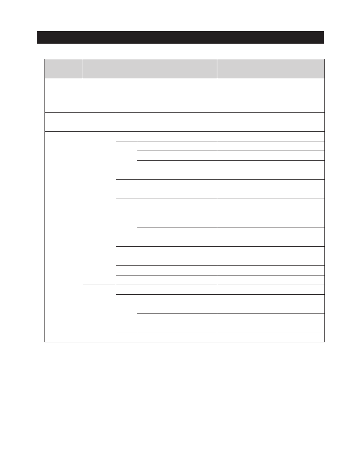
2-1. Compartment Features by Model ................................................................................................................10
2-2. Basic Product Specifications (inch/mm) ......................................................................................................11
2-3. Comparison of Specifications (inch, mm) ................................................................................................... 12
2-4. Specifications ................................................................................................................................................. 16
2-5. Dimensions ....................................................................................................................................................18
2-6. ICE-MAKER Function .................................................................................................................................. 20
2-7. Material Specification ....................................................................................................................................22
3. Disassembly and Reassembly ................................................................. 23
3-1. Precautions ................................................................................................................................................... 23
3-2. Disassembling the Refrigerator Door ......................................................................................................... 24
3-3. Disassembling the Fridge Doors (RF24J* only) ........................................................................................ 26
3-4. Assembing the Fridge Doors (RF24J* only) ............................................................................................. 28
3-5. Assy Auto Hinge .......................................................................................................................................... 29
3-6. Braket (RF24J* only) .................................................................................................................................... 30
3-7. Door Soft Damper (RF24J* only) ................................................................................................................. 31
3-8. Disassembling the Freezer Doors .............................................................................................................. 32
3-9. Assembling the Freezer Doors................................................................................................................... 33
3-10. Disassembling the Display ........................................................................................................................ 34
3-11. Disassembling the Main PCB and Inverter PCB ...................................................................................... 35
3-12 Dispenser ..................................................................................................................................................... 36
3-13. Case Water Filter .........................................................................................................................................37
3-14. Water Filter (Assembly & Disassembly) ................................................................................................... 38
3-15. Disassembling the REF EVAP Cover ....................................................................................................... 39
3-16. Disassembling the FRE EVAP Cover ....................................................................................................... 40
3-17. Disassembling the Machine Compartment Motor Fan ............................................................................. 41
3-18. Disassembling the Relay Protector O/L ................................................................................................... 42
3-19. Disassembling the Step Valve .................................................................................................................. 43
3-20. Disassembling the Fridge Internal Lamp ................................................................................................. 44
3-21. Disassembling the Freezer Internal Lamp ............................................................................................... 44
3-22. Disassembling the Tempered Glass Shelf .............................................................................................. 45
3-23. Vegetable shelf .......................................................................................................................................... 45
3-24. CHEF PANTRY ........................................................................................................................................... 46
3-25. Disassembling the French .........................................................................................................................47
3-26. REF Evaporator .......................................................................................................................................... 48
3-27. FRE/Cool Select Room Evaporator .......................................................................................................... 48
3-28. ASSY RAIL .................................................................................................................................................. 49
3-29. Ice-Maker ................................................................................................................................................... 50
3-30. Auger Motor Fan ....................................................................................................................................... 52
3-31. ASSY GUARD DISPENSER ........................................................................................................................ 53
3-32. Assy Sparking Kit ...................................................................................................................................... 54
3-33. ASSY GUARD UTILITY ............................................................................................................................... 55
3-34.
Descriptions of CO2 Cylinder Installation and Sparkling Water Functions
(only for RF33H9960S4)
...................56
3-35. USING THE MAIN CONTROL PANEL ....................................................................................................... 62

4
CONTENTS
4. Troubleshooting ....................................................................................69
4-1. Functions for failure diagnosis .................................................................................................................... 69
4-1-1. Test mode (manual operating / manual defrosting function) ...................................................... 69
4-1-2. Display function of Communication error ....................................................................................... 71
4-1-3. Self-diagnostic function ..................................................................................................................72
4-1-4. Display function of Load condition .................................................................................................77
4-1-5. Display function of Load condition (Sparkling water model) .......................................................79
4-1-6. Cooling Off Mode setting function ................................................................................................. 80
4-1-7.
AP Mode Function and E-Smart Icon ................................................................................................... 80
4-1-8. Option setting function ..................................................................................................................... 81
4-1-9. Option TABLE .................................................................................................................................. 83
4-2. Troubleshooting by symptom ..................................................................................................................... 88
4-2-1. When there is no power at Inverter PCB (F/R Room Inverter) .................................................. 88
4-2-2.
The LED blinking frequency depending on the protection functions (F/R Room Inverter PCB)
........... 90
4-2-3.
When a "1E","2E", "4E", "5E", "6E", "7E", ''9E, "11E", "13E", "24E", "29E" error occures(defrosting failure)
.........91
4-2-4. When occur the cooling defect by a lot of frosting on the Fridge compartment ........................ 92
4-2-5. When an error occurs in self diagnostic mode (in case of a sensor error) ............................ 93
4-2-6. When the Fan does now operate(F, R, CV, C-FAN) ................................................................. 94
4-2-7. When the Fan does now operate (ICE ROOM - FAN) .............................................................. 95
4-2-8. When the ICE MAKER does not operate ..................................................................................... 96
4-2-9. When water does not supply at Ice Maker ..................................................................................97
4-2-10. When Cubed or Crushed ice does not dispense properly ..................................................... 98
4-2-11. When COVER ICE ROUTE MOTOR (GEARED MOTOR) does not work properly ................... 99
4-2-12. When the alarm is heard continuously (buzzer sound) ...........................................................100
4-2-13. When the DISPENSER Panel PBA does not work properly ....................................................102
4-2-14. When the MAIN Panel PBA does not work properly ...............................................................103
4-2-15. When the Micro Hole Panel PBA does not work properly ......................................................104
4-2-16.
When the internal LED Lamp of the F-Room or R-Room or Cool select-room is not turned on
.............105
5. PCB Diagram ...................................................................................... 108
5-1. PCB Layout with part positions (Main Board) ...........................................................................................108
5-2. Inverter PCB Layout positions ...................................................................................................................109
5-3. Connector Layout with part positions (Main Board) ................................................................................ 110
5-4. Connector Layout with part positions ........................................................................................................ 111
6. Wiring Diagram ....................................................................................112
6-1. Sparkling/Dispenser Model .........................................................................................................................112
6-2. Dispenser Display+SODA PBA .................................................................................................................113
7. BLOCK DIAGRAM .................................................................................114
7-1. Dispenser + Sparkling + MHD ....................................................................................................................114
7-2. Whole block diagram (ISB-LC5) ................................................................................................................115
8. References .......................................................................................... 116
8-1. Glossary .........................................................................................................................................................116
8-2. French Heater Control Using a Humidity Sensor .....................................................................................118
8-3. Model Numbering Convention ....................................................................................................................119
8-4. Troubleshooting. Check the following before calling the service centre .............................................120
8-5. Optimum Operating Environment for Sparkling water ............................................................................126

5
1. PRECAUTIONS (SAFETY WARNINGS)
● Unplug the appliance before replacing or repairing electrical parts.
⇒ Be careful to avoid electric shock.
● Always use only the correct replacement parts.
⇒ Check the model name, rating voltage, rating current, running temperature
symbols.
● When troubleshooting, verify that wiring harnesses are connected securely.
⇒ Make sure the connectors are not separated when power is supplied.
● Check for visible traces of water on electrical parts.
⇒ Replace or secure any part that may have come in contact with water.
● Check the status of parts after replacement or troubleshooting.
⇒ All parts must be reinstalled properly.
● Check the location where the refrigerator will be used.
⇒ If the refrigerator will be used in a damp or wet space, or if installation will be
unstable, the unit should be relocated.
● The refrigerator must be grounded properly.
⇒ An earth ground should be used if there is a risk of high humidity or wetness.
● The refrigerator should be plugged into a dedicated outlet.
⇒ Make sure the power cord is not damaged, crushed, squeezed or burned. If
the plug is damaged it should be replaced.
⇒ If the socket is damaged, it should not be used.
● Consumers must not try to repair the refrigerator.
● Nothing should be stored in the refrigerator except food.
⇒ Drugs requiring precise temperatures should not be stored in the refrigerator.
⇒ Flammable substances (alcohol, benzene, ether, LP gas, etc.) carry risk of
explosion and should not be stored in the refrigerator.
6
PRECAUTIONS(SAFETY WARNINGS)
Read all instructions before repairing the product and follow the instructions
in order to prevent danger or property damage.
Plug out and remove all the items in regrigerator prior to repair.
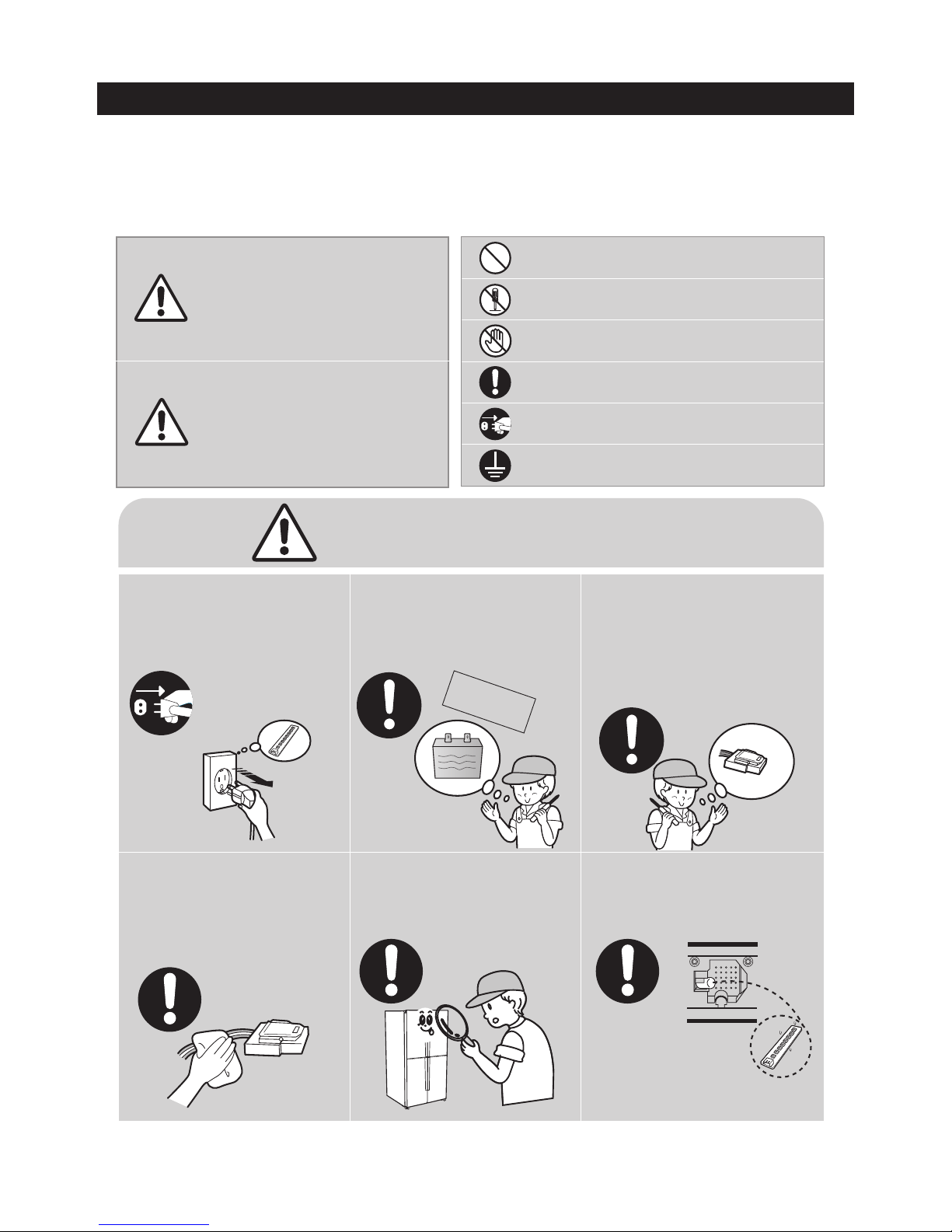
CAUTION/WARNING SYMBOLS DISPLAYED
SYMBOLS
Indicates that a
danger of death
or serious injury
exists.
Indicates that a risk
of personal injury
or material damage
exists.
means "Prohibited".
means "Do not disassemble".
means "No contact".
means "Warning or Caution".
means "Earth or Ground".
means "Unplug the unit before
preforming service"
Unplug to exchange the interior
lamp.
• It may cause electric shock.
Warning
Warning & Caution
Caution
Unplug
Use the rated components
on the replacement.
• Check the correct model, rated
voltage, rated current, operating
temperature and so on.
On repair, make sure that the
all wiring harnesses are
reconnected.
• Wiring harnesses should be connected
tightly and kept dry.
• Bundle tightly wires in order not to be
detached by the external force and then
not to be wetted.
Check for visible traces of water on
electrical parts.
• Replace or secure any part that may have
come in contact with water.
Check the status of parts after
replacement or troubleshooting.
•
All parts must be reinstalled properly.
On repair, Make sure that all parts
and wires are free of dust and
debris.
• Cleaning parts could help prevent fire or
shorting.
Rated
components
7
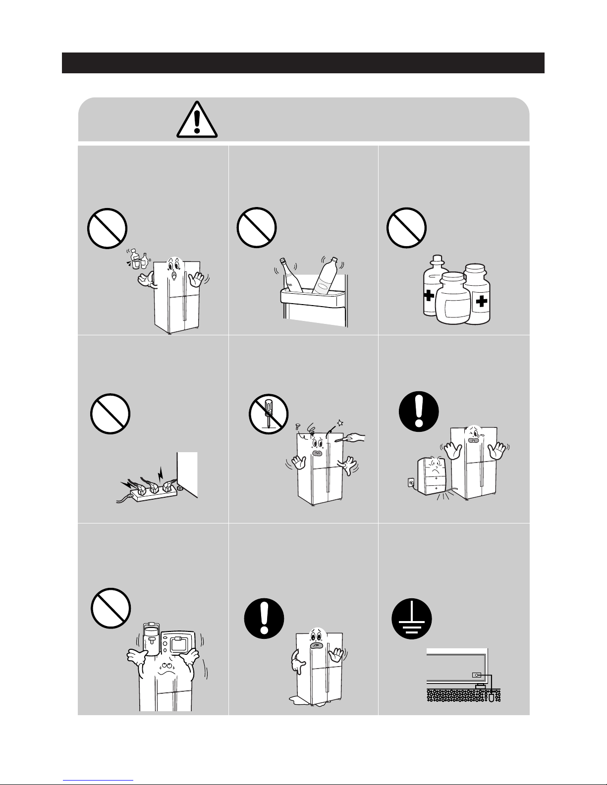
PRECAUTIONS(SAFETY WARNINGS)
❈ Please let users know following warnings & cautions in detail.
Customers should not store glass
bottles of liquid in the freezer section.
Frozen bottles could explode and
cause injury.
Customers should not store narrow
or long bottles or food in a small
door shelf.
• These items could fall when the door is
opened, causing injury tot he customer.
Drugs requiring precise
temperatures should not be stored
in the refrigerator.
Articles on the product.
• Opening or closing the door may cause
things to fall down, which may cause
injury.
Prohibition
Warning & Caution
Consumers must not try to
repair the refrigerator.
• Electrical and mechanical parts could
injure the consumer.
Do not
disassemble
The refrigerator should be
plugged into a dedicated outlet.
• Multiple plugs in the outlet could cause
excessive heat or fire.
Prohibited
Make sure the power cord is not
damaged or crushed.
• A damaged cord could cause excessive
heat or fire.
Check the location where the
refrigerator will be used.
• If the refrigerator will be used in a
damp or wet space, or if installation will
be unstable, the unit should be
relocated.
The refrigerator must be
grounded properly.
• An earth ground should be used if
there is a risk of high humidity or
wetness.
Earth
8
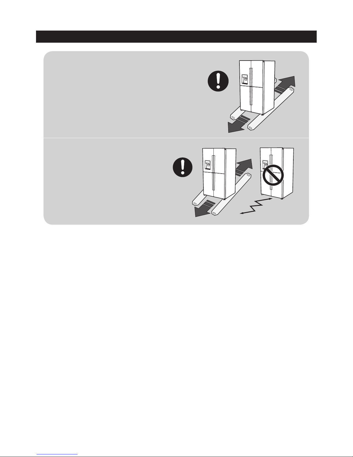
PRECAUTIONS(SAFETY WARNINGS)
For proper installation, this refrigerator must be
placed on a level surface of hard material that is the
same height as the rest of the flooring. This surface
should be strong enough to support a fully loaded
refrigerator, or approximately 660 lb (299kg).
FLOORING
Protect the finish of the flooring. Cut a large
section of the cardboard carton and place
under the refrigerator where you are working.
When moving, be sure to pull the unit straight
out and push back in straight.
MOVING

9
2. PRODUCT FEATURES AND SPECIFICATIONS
Product Features
Cool Select Room ▶ You can store various foods by selecting a mode from among
'Freezer,' 'Soft Freezer,' 'Chill,' and 'Cool' modes. You can set it to
be a fridge compartment if you have more foods for refrigeration
and to be a freezer compartment if you have more foods to be
frozen.
Chef Mode ▶ It controls the temperature minutely by letting the temperature
sensor inside the refrigerator sense the temperature more
frequently. It makes a fresh storage environment by minimizing
the changes of foods by temperature changes.
Chef Pantry ▶ You can store meat or fish fresh, and can store foods of size up
to a pizza box of 13" (48 cm).
Moisture Care Technology
and Triple Independent
Cooling Method
▶ It maintains the taste and flavor of foods' own by the triple
independent cooling method, which is an upgraded version of
the moisture care technology of Zipel's own, and keeps foods
fresh for a long time by maintaining the humidity inside the fridge
compartment at around 70%.
10
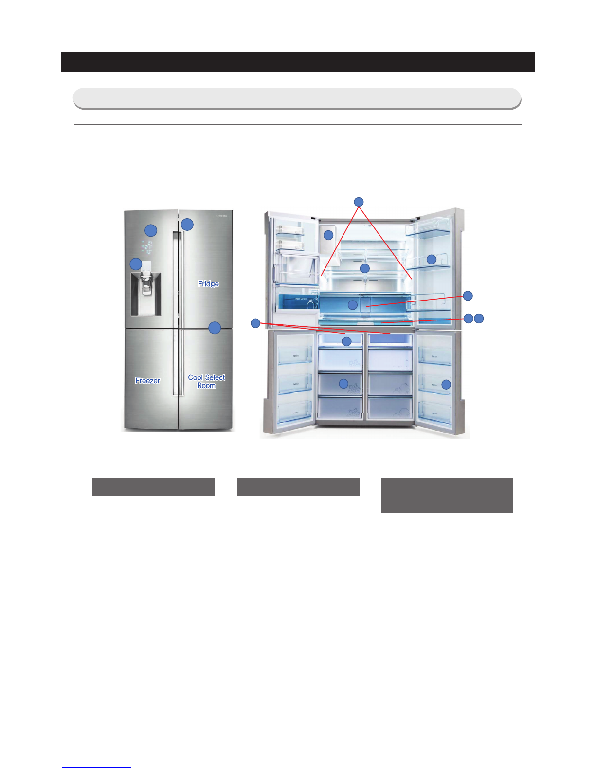
PRODUCT FEATURES AND SPECIFICATIONS
2-1. Compartment Features by Model
Appearance
A) Handle
B) Buttons
C) Indicators
Freezer Compartment /
Cool Select Room
7) Freezer lamps
8) Freezer shelf
(only for RF34H99*)
9) Freezer drawer
10) Freezer door bins
* Egg trays
Fridge Compartment
1) Refrigerator lamps
2) Refrigerator shelf
3) Refrigerator drawer
4) Refrigerator door bins
5) Water filter
6) Auto ice maker
11) Chef pan
12) Chef panty
A
B
C
B
1
2
3
4
5
6
7
8
9
10
11 12
Water Dispenser model :
RF34H99*, RF24J99*
11
PRODUCT FEATURES AND SPECIFICATIONS
2-2. Basic Product Specifications (inch/mm)
Item Specifications
Model no.
RF34H99*
RF24J99*
External dimensions
(width x depth x height)
35 3/4” X 35 3/4” X 72 7/8”
(908 X 906 X 1850)
35 6/8” X 28 7/8” X 68 7/8”
(908 X 733 X 1777 mm)
Packing dimensions
(width x depth x height)
38 1/4” X 38 1/4” X 79 3/8”
(972 X 972 X 2018)
38 1/4” X 31 1/4” X 76 1/8”
(972 X 795 X 1934 mm)
Rated power frequency (HZ) 60 60
Rated power (V) 115 115
Rated power consumption of the
electric motor (W)
145 145
Rated power consumption of the
electric heater (W)
370 370
Refrigerator type Indirect cooling type refrigerator Indirect cooling type refrigerator
Refrigerant
Freezer / Cool Select Room / Ice
Room : R-134a
Fridge : R-134a
Freezer / Cool Select Room / Ice
Room : R-134a
Fridge : R-134a
Amount of sealed refrigerant
Freezer / Cool Select Room / Ice
Room : 6.00 oz(170 g)
Fridge : 3.53 oz(100 g)
Freezer / Cool Select Room / Ice
Room : 6.00 oz(170 g)
Fridge : 3.53 oz(100 g)
Weight (kg)
533.51 lb (242 kg) 438.72 lb (199kg)
Packing weight (kg)
559.97 lb (254 kg) 461.65 lb (209.4kg)
12
PRODUCT FEATURES AND SPECIFICATIONS
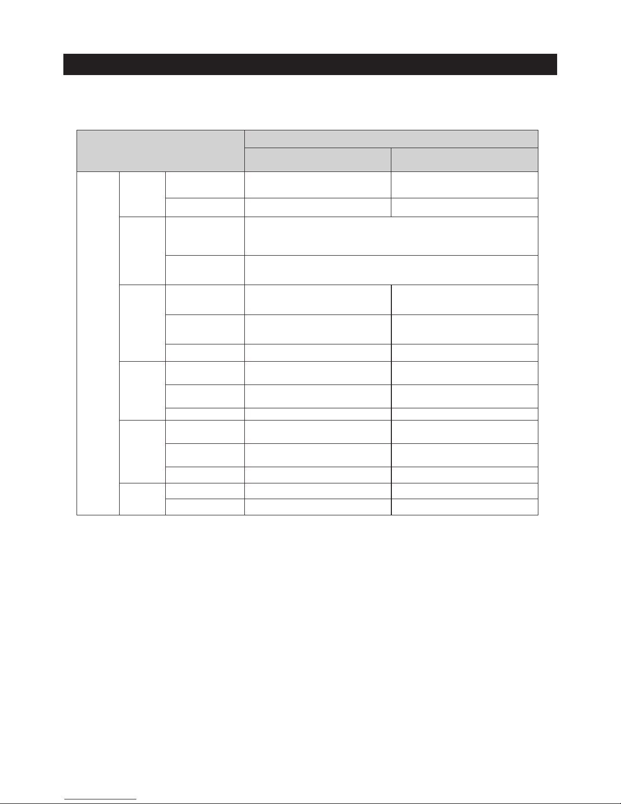
No. Module RF34H99* RF24J99*
1 Dimensions
35 3/4” X 35 3/4” X 72 7/8”
(908 X 906 X 1850)
35 6/8” X 28 7/8” X 68 7/8”
(908 X 733 X 1777 mm)
2 Door SWING 4 Door/ STS ←
3 Lighting
Fridge SIDE: 4 PILLAR LAMP ←
Freezer/
Cool Select
TOP: 1 LED (1EA, High-luminance LED
Lamp), FRIDGE DOOR BOTTOM:
1 LED(1EA, High-luminance LED Lamp)
←
4 Shelf
Fridge Slide, FIX/ AL Foil-Trim ←
Freezer/
Cool Select
Tray Shelf / AL Foil-Trim -
5 Box
Fridge 3 Pieces / AL Foil-Trim ←
Freezer/
Cool Select
3 Pieces / AL Foil-Trim ←
6 Cool Select Room modes Freezer / Soft Freezing / Chill / Cool ←
7 Ice Maker Direct cooling system Auto I/M ←
8
Guard
Fridge Transparent 2 piece
←
Freezer/
Cool Select
Transparent 2 piece ←
9 Egg tray Transparent 1 piece ←
10 Handle Hidden handle ←
11 Display LED ←
12 VIP
VIP 9 sheets (cabi side/rear/up,
liner bottom, door ref/fre)
←
13 Back cluster Applied ←
2-3. Comparison of Specifications (inch, mm)
13
PRODUCT FEATURES AND SPECIFICATIONS
Item
Item RF34H99*, RF24J99*
Specifications
Cycle, Refrigerant
Dual Comp.
F/CV/Ice Room: R134a (6.00 oz(170 g))
R Room: R134a (3.53 oz(100 g))
Compressor
F/CV/Ice Room: MKV190CL2B/E01
R Room: NC1MV43AMP
Ice-making performance
Normal 0.056oz(1.6kg)/day↑
Worst 0.035oz(1.0kg)/day↑
Notch
(Freezer/Cool
Select/Fridge)
* Detailed
information table
appended,
C-C-C
Freezer 1/3H -8±2.7℉(-23±1.5℃)
Cool
Select
1/3H
Freezer -8±2.7℉(-23±1.5℃)
Soft Freezing 23±3.6℉(-5±2.0℃)
Chill 30±3.6℉(-1±2.0℃)
Cool 41±3.6℉(5.0±2.0℃)
Fridge 1/3H 34℉±2 7℉(1±1 5℃)
N-N-N
Freezer 1/3H 0±2.7℉(-18±1.5℃)
Cool
Select
1/3H
Freezer 0±2.7℉(-18±1.5℃)
Soft Freezing 23±3.6℉(-5±2.0 ℃)
Chill 30±3.6℉(-1±2.0 ℃)
Cool 41±3.6℉(5.0±2.0 ℃)
Fridge 1/3H 37±2.7℉(3±1.5℃)
Freezer temperature distribution 36℉↓(20℃)
Cool Select temperature distribution 36℉↓(2.0℃)
Fridge temperature distribution 3.6℉↓(2.0℃)
Operating ratio 100% ↓
W-W-W
Freezer 1/3H 5±2.7℉(-15±1.5℃)
Cool
Select
1/3H
Freezer 5±2.7℉(-15±1.5℃)
Soft Freezing 23±3.6℉(-5±2.0 ℃)
Chill 30±3.6℉(-1±2.0 ℃)
Cool 41±3.6℉(5.0±2.0 ℃)
Fridge 1/3H 44±2.7℉(7±1.5℃)
14
PRODUCT FEATURES AND SPECIFICATIONS
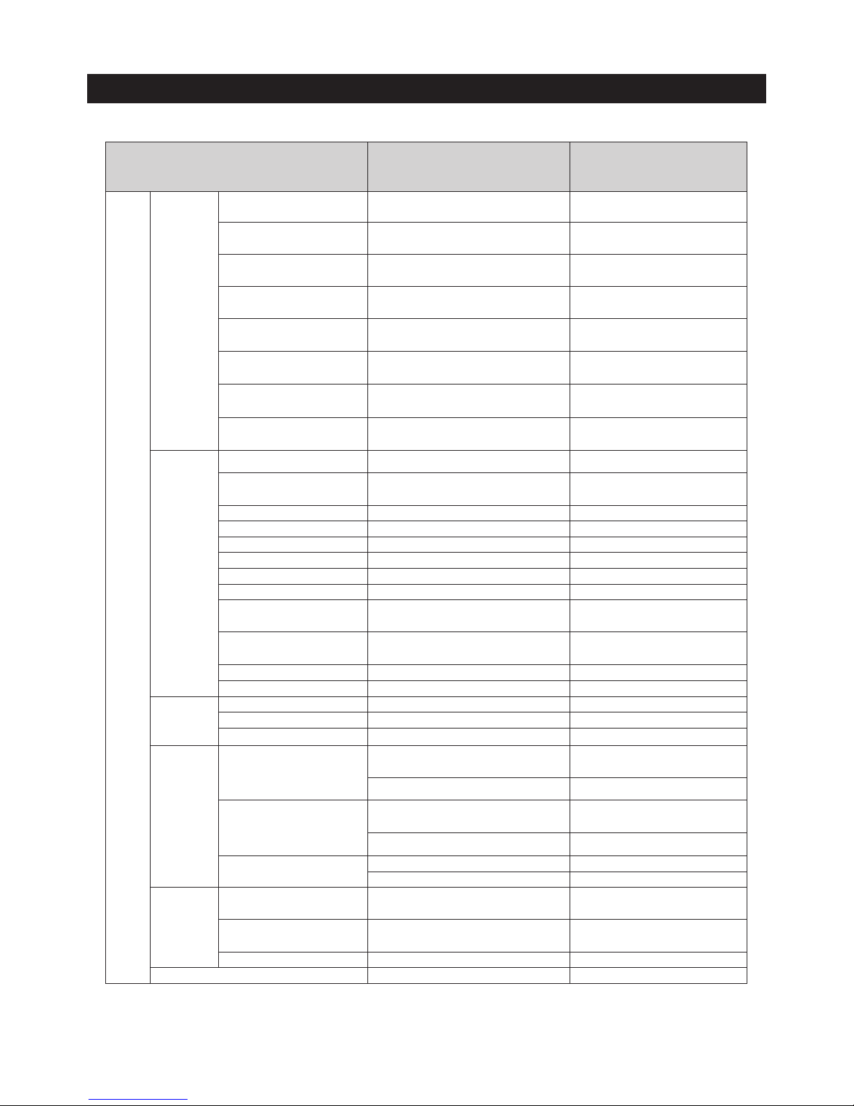
Item
RF34H99*, RF24J99*
Freezer, Cool select, Ice room
cycle (parallel)
Fridge cycle
Cycle
Specifications
Compressor
Model no. MKV190CL2B/E01 NC1MV43AMP
Amount of refrigerant R134a (6.00oz(170g)) R134a (3.53oz(100g))
Evaporator
Freezer/
Cool Select Room
3 rows 2 layer, Depth 70mm
Fridge Compartment 3 rows 2 layer, Depth 70mm
Condenser
Condenser
SFC (Serpentine Flow Condenser) 3
rows
SFC (Serpentine Flow Condenser) 2rows
Cluster pipe -
Side Cluster: Not applied
Back Cluster: OD4.0(t 0.7), 4.94m
Hot pipe OD4.0(t 0.7), 11.4m
-
Suction
Cool select -
Freezer Pipe
OD7.94(t 0.5), 0.785m
-
Freezer - Ice Maker
connection Pipe
OD7.0(t 0.5), 2.5m
-
Suction pipe OD7.94(t 0.5), 2.5m OD7.94(t 0.5), 3.0m
Capillary
Tube
Freezer capillary
Tube
OD2.05, ID0.82, 3500mm
-
Cool Select capillary
Tube
OD1.9, ID0.82, 3300mm -
Fridge capillary tube - OD1.9, ID0.82, 3500mm
Other
Dryer Step valve Single Dryer
Valve Step valve (3 way) -
15
PRODUCT FEATURES AND SPECIFICATIONS
Classification RF34H99*, RF24J99*
Remarks
Electrical
parts
Motor
&
Fan
Freezer
BLDC(ARES2120RA), ø120 11Wing,
DC12V, 2.5W, 1870rpm
AIO Q7
Cool Select Room
BLDC(ARES2120RA), ø120 11Wing,
DC12V, 2.5W, 1870rpm
AIO Q7
Fridge
BLDC(ARES2120RA), ø120 11Wing,
DC12V, 2.5W, 1870rpm
AIO Q7
Machine compartment
BLDC(DRCP8020LA), ø160 3Wing,
CCW 12VDC 1.7W, 1120rpm
AIO 160
PANTRY
BLDC(U92C12MS1B3-52K09), 92*92*32,
3Wing, DC12V, 0.16A, 3350rpm
BOX FAN
ICE ROOM
BLDC(2606JL-04W-S39), 66*66*15,
9Wing,DC12V, 1.2W, 3600rpm
BOX FAN
AUGER
AC 120V/60Hz, LONG SHAFT, CCW,
18 RPM
GEARED
DISPENSER
AC 120V/60Hz, Syncronous, CCW, 18
RPM
GEARED
Heater
F-Evap. AC120V 121(Sheath Heater)
CV-Evap. AC120V 121(Sheath Heater)
Common to both the F and CV
compartments
R-Evap. Not applied.
French
AC120V 10W(Cord Heater)
Door F DC12V 2.5W(Cord Heater)
Door CV DC12V 2.5W(Cord Heater)
Door R Not applied.
Dispenser AC120V 2.5W
Water pipe
DC12V 2.3W
(Cord Heater)
ICE Room
DC12V 2W
(Cord Heater)
ICE Maker AC120V 120W
Damper Not applied.
Comp
electrical
parts
OLP 4TM445PHBYY-82
PTC Relay Not applied.
Capacitor Not applied.
Over
Heater
Protector
Freezer
Bimetal
[Off : 140°F (60°C) / On : 104°F (40°C)]
Thermal Fuse [Cut-off 230℉ (110℃)]
Cool Select Room
Bimetal
[Off : 140°F (60°C) / On : 104°F (40°C)]
Thermal Fuse [Cut-off 230℉ (110℃)]
Fridge
Not applied.
Not applied.
Internal lamp
Freezer
TOP: 1 LED(1EA) / FRIDGE DOOR
BOTTOM: 1 LED(1EA)
Cool Select Room
TOP: 1 LED(1EA) / FRIDGE DOOR
BOTTOM: 1 LED(1EA)
Fridge SIDE: 12 LEDs(4EA)
3 Way Valve Stepping Motor (NSCEV01TA*)

16
PRODUCT FEATURES AND SPECIFICATIONS
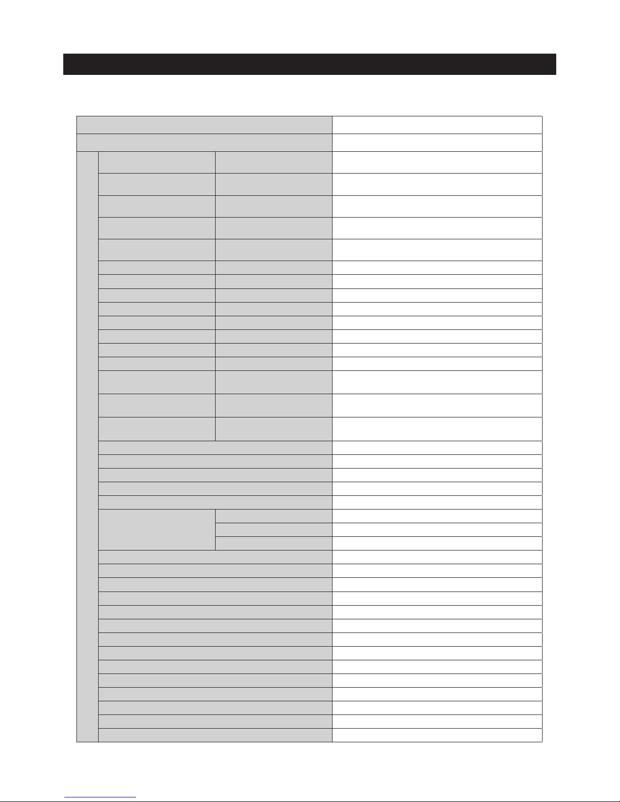
2-4. Specifications
Item
Dimensions
Temperature sensors inside Compartment
Freezer
Thermistor
(F-Sensor)
Temp. Selection
Threshold that turns the
sensor output on
Thresholds that turns the sensor
output off
-8℉
-5℉(-21℃) -11℉(-24℃)
0℉
3℉(-16℃) -3℉(-19℃)
5(℉)
8℉(-14℃) 2℉(-17℃)
Cool Select Room
Thermistor
(R-Sensor)
Freezer Same as Freezer compartment Same as Freezer compartment
Soft Freezing
27℉(-3℃) 19℉(-7℃)
Chill
33℉(1℃) 26℉(-3℃)
Cool
45℉(7℃) 37℉(3℃)
Fridge
Thermistor
(R-Sensor)
34℉
37℉( 3℃) 31℉( 0℃)
37℉
40℉(4℃) 34℉(1℃)
44(℉)
47℉(8℃) 41℉(5℃)
Defrosting Parts
Defrosting sensor
F defrosting - sensor
Model no.
THERMISTOR (DTN-C502)
Specifications
5.0 ㏀ at 77℉ (25℃)
R defrosting - sensor
Model no.
THERMISTOR (DTN-C502)
Specifications
5.0 ㏀ at 77℉ (25℃)
Bimetal (Freezer)
Model no.
BIMETAL THERMOSTAT (BT-121-M)
Operating temperature
Off : 140°F (60°C) / On : 104°F (40°C)
Bimetal (Cool select)
Model no.
BIMETAL THERMOSTAT (BT-121-M)
Operating temperature
Off : 140°F (60°C) / On : 104°F (40°C)
17
PRODUCT FEATURES AND SPECIFICATIONS
Item Dimensions
Model
RF34H99*, RF24J99*
Electrical parts
Freezer compartment defrosting
heater
Current flows when F defrosting is
conducted.
AC120V 121W
Cool Select compartment defrosting
heater
Current flows when CV defrosting is
conducted.
AC120V 121W
Fridge compartment defrosting heater
Current flows when R defrosting is
conducted.
-
Cool Select compartment drain
heater
Current flows when CV defrosting is
conducted.
-
French heater
According to external humidity ,
Heater is operated
AC120V 10W
Water tank heater -
-
Dispenser heater -
AC120V 2.5W
Cap door heater (R compartment) -
-
Display heater (F compartment) -
-
Ice water supply pipe heater -
-
Ice water drain pipe heater -
DC12V 2.3W
ICE Room Heater -
DC12V 2W
Damper heater
-
-
Freezer compartment door heater
The heater is operated by the
external humidity sensor.
DC 12 V 2.3 W
Cool Select compartment door heater
The heater is operated by the
external humidity sensor.
DC 12 V 2.3 W
Fridge compartment door heater
The heater is operated by the
external humidity sensor.
-
Freezer compartment defrosting heater overheating prevention bimetal
Off: 140℉(60℃) / On: 104℉(40℃)
Freezer compartment defrosting heater overheating prevention fuse
230℉ (110℃), 120V/15A
Cool Select compartment defrosting heater overheating prevention bimetal
Off: 140℉(60℃) / On: 104℉(40℃)
Cool Select compartment defrosting heater overheating prevention fuse
230℉ (110℃), 120V/15A
Noise filter
20 mH, 80*60*1.6 t
OLP
Model no.
4TM445PHBYY-82
Temperature at which it turns on
156.2°F (69°C)
Temperature at which it turns off
257°F (125°C)
Freezer compartment cooling fan motor
DC 12V BLDC(ARES2120RA)
Cool Select compartment cooling fan motor
DC 12V BLDC(ARES2120RA)
Fridge compartment cooling fan motor
DC 12V BLDC(ARES2120RA)
Comp. cooling fan motor
DC12V BLDC(DRCP8020LA)
PANTRY
DC 12V BLDC(U92C12MS1B3-52K09)
ICE ROOM
DC 12V BLDC(2606JL-04W-S39)
AUGER
AC 120V/60Hz, Shading pole(ISG-3240SSJ)
DISPENSER
AC 120V/60Hz, Syncronous(MVCD18AR19)
Motor step valve
DC 14 V / 0.7 A
Freezer / Cool Select Room interior lamps
TOP: 1 LED(1EA), FRIDGE DOOR BOTTOM: 1 LED(1EA)
Fridge interior lamps
SIDE: 12 LEDs(4EA)
Door reed switch
DC 200 V / 0.5 A
Power cord
125V/15A
Grounding screw
BSBN (brass screw)
18
PRODUCT FEATURES AND SPECIFICATIONS
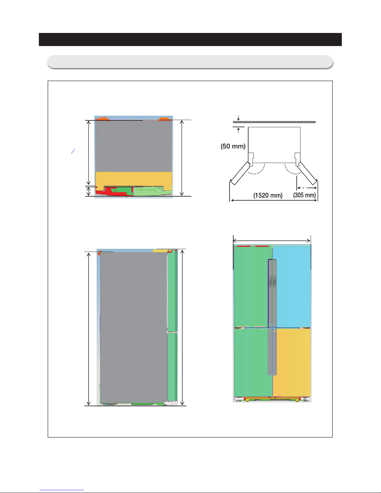
2-5. Dimensions
35 3/4"
(908 mm)
35 ¾” (908 mm)
72 ⅞”
(1850 mm)
71 ¾”
(1822 mm)
30
15
16
”
(785 mm)
4 ⅜"
(112mm)
59 3/4”
12”
123° 123°
2”
RF34H99*
19
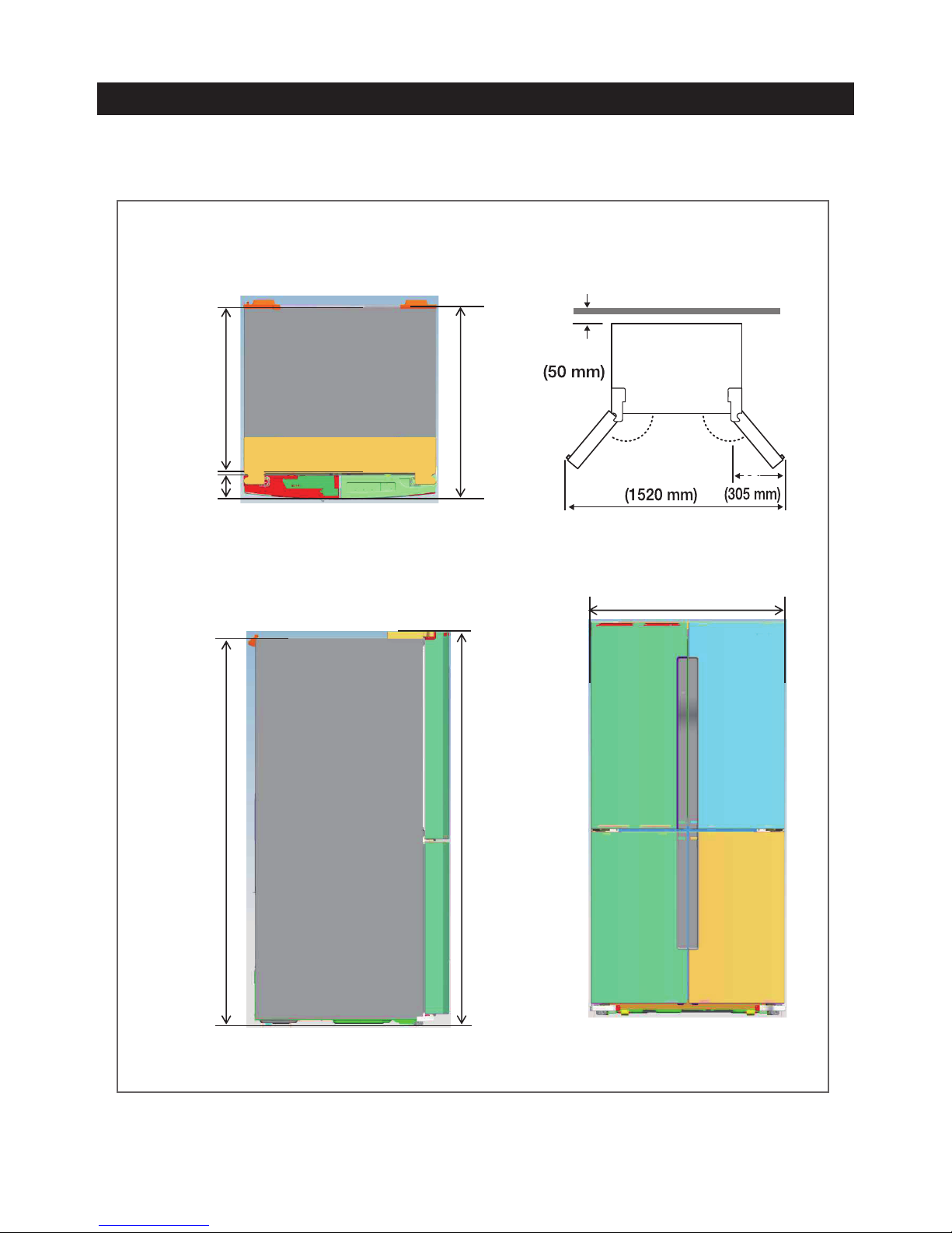
PRODUCT FEATURES AND SPECIFICATIONS
28 7/8"
(733mm)
35 ¾” (908 mm)
70"
(1777m)
68 7/8"
(1749mm)
24"
(610mm)
4 ⅜"
(112mm)
59 3/4”
12”
123° 123°
2”
RF24J99*
20
PRODUCT FEATURES AND SPECIFICATIONS
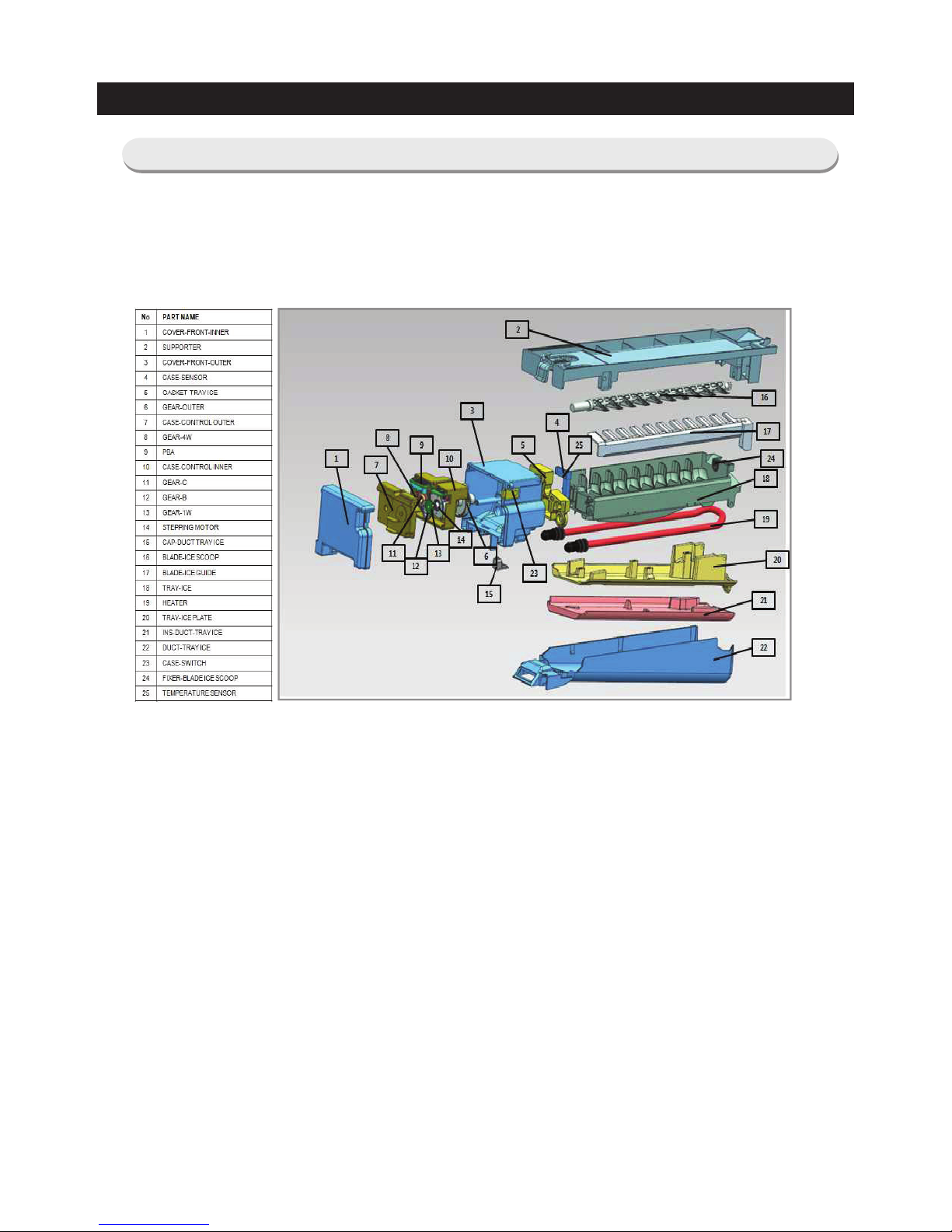
2-6. ICE-MAKER Function
- The ICE-MAKER function is an option and the following explains the function of these models.
- The ICE-MAKER is a kit that supplies water on its own, freezes water into ice and stores the ice cubes in the Ice
Container with the capability of making ice automatically without manual controlling
1) ICE-MAKER Components
2) Initial Operations
1. When the power is on, it checks the temperature of the Ice Maker Sensor. If the Ice Maker Sensor
temperature is lower than 0℃, the Ice Maker Heater will be on for 4 minutes. After that, it will run the Initial
Test Mode. If the Ice Maker Sensor temperature is higher than 0℃, it will run the Initial Test Mode right
away.
2. During the Initial Test Mode, it carries out the operation of the Ice Maker Motor and its Heater turns on for
30 seconds.
3. If the Ice Maker Sensor temperature is over 0℃ upon the initial power on, the Water Valve will work for a
second while its Heater is on.
4. The Ice Maker Motor rotates both clockwise and counter clockwise repeatedly. And, when it is sensed as
being at the parallel position (Home) within 6 minutes after the Motor starts operating, its initial operation will
stop and its normal ice making will begin.
5. When it does not sense the parallel position (Home) within 6 minutes after the Motor starts operating, it will
be considered as the Ice Maker defect and its initial operation will stop.
※ Operation upon Ice Maker Defect during the Initialization.
1) Upon the termination of the Initialization due to the Ice Maker Defect, it runs the Initialization again. And, when
the defect is detected during all the set number of times (ex. 3 times), it will stop the Initialization of the Ice Maker.
2) When it is sensed as defect 3 times in a row during the initialization, the Ice Maker does not operate for the
set duration (ex. 3 hours) and it runs the initialization again after a set time period.
21
PRODUCT FEATURES AND SPECIFICATIONS
3) General Operation
•
Water Supply > Stand-by Time for Ice Making > Temperature Checking for Ice Maker Sensor > Ice Removing
Water Supply Ice Making Ice Removing
1. After supplying water, it stands by for 14 minutes before starting the ice making. After that, it checks the Ice Maker
Temperature.
2. When the Ice Maker Sensor temperature is measured lower than -13℃ for more than 5 seconds, its ice making
is completed.
3. When the ice making is completed, the Ice Maker Heater and Motor operates and the ice cubes are to be
removed from the Ice Maker. At this time, its heater thaws out the outer surface of the ice cubes allowing them to
be removed from the Ice Maker easily. And, its motor turns both clockwise and counter clockwise to remove the
ice cubes from the Ice Maker.
4. The Ice Maker repeats the operation of the (1) ~ (3) until ice cubes build up in the Ice Bucket triggering the Full-
Ice Detect Sensor on. At this time, the Ice Maker stops producing ice cubes.
4) Ice Off (Stopping Ice Making) Function
1. When turning on the Ice Off function at the preference setting, the Ice Maker function will be off.
2. When the Ice Maker is off, it does not supply water to the Ice Tray.
3. When turning off the Ice Off function, the Ice Off function will be cancelled. When the Ice Off is cancelled, it starts
from ice making and the operation of the Ice Maker resumes.
5) TEST Function
- It is a function to be used when it needs the forced operation for the purpose of repairs or cleaning.
1. When pressing the Test Button for 1.5 seconds, the Test Function will start.
2. The Test Function works as follows.
Start (Alarm Sound) → Motor On (Rotating Counter Clockwise) → Motor On (Rotating Clockwise) → Heater On →
Motor On (Rotating Clockwise) → Home Location → Water Supply → Completed (Alarm Sound)
※ The Ice Maker Heater will be On / Off
The Ice Maker Heater will be On and Off according to the temperature conditions of the Ice Maker Sensor when
the Ice Maker Motor rotates clockwise.
3. When the entire operation is to be completed within 6 minutes after the motor starts operating upon pressing the
Test button, it sends out alarm sound. And, after this, it does normal ice making.
4. When the entire operation does not complete normally (ex. Not reaching at the Home location) within 6 minutes
after the motor starts operating upon pressing the Test button, it will be considered as the Ice Maker defect and
the entire loads (Motor, Heater, etc) will be off. (No alarm sound)
After this, it performs an operation checking whether the Ice Maker operates normally according to the set time
cycle (ex. 3 hour).
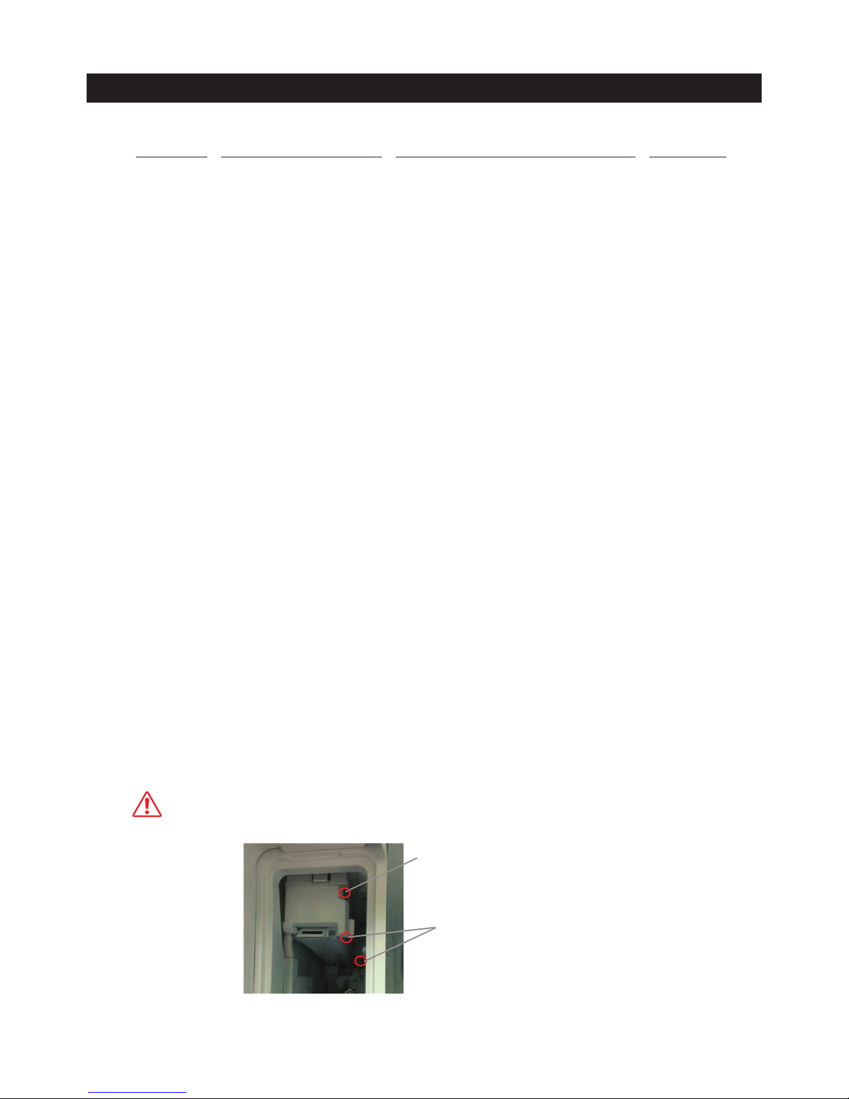
Ice Level Checking IR Sensor
Ice maker test switch
Caution
When the Ice Maker Heater is on, it may cause personal injury. So, take extra care
22
PRODUCT FEATURES AND SPECIFICATIONS
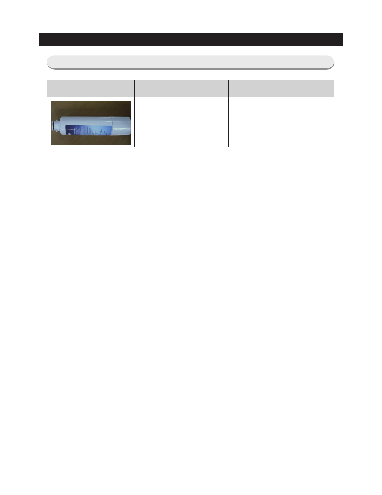
2-7. Material Specification
Photograph Part Name Part Code AMOUNT
FILTER WATER-ASSY DA29-00019B 1
23
3.
DISASSEMBLY AND REASSEMBLY
3-1. Precautions
• Before replacing or repairing an electrical part, be sure to unplug the product's power cord.
- Failing to do so may result in electric shock.
• Be sure to replace any electrical parts with rated parts.
- Be sure to check the model no, rated power voltage, operating temperature etc. printed on the product.
• When repairing a product, connect the harnesses firmly so that no water enters the product.
- They should not become separated if a certain amount of force is applied.
• When repairing the product, completely remove all dust or foreign substances from the housing, connectors and
terminals.
- Prevents fire due to tracking or short-circuits.
• Check if there are any marks of moisture having entered the electric parts.
- If it appears that moisture has penetrated the part, take countermeasures such as replacing the part or wrapping
the part with insulation tape.
• After fixing a problem, check the assembly status of the parts.
- The status must be the same as before repairing the product.
• Check the operating environment of the refrigerator.
- If the refrigerator is exposed to moisture or is installed near water or on an unstable surface, relocate the
refrigerator.
• Ground the refrigerator if necessary.
- In particular, if there is a danger of electric leakage due to moisture or water, be sure to ground the refrigerator.
• Do not share a power strip with other appliances.
• Check if the power plug or electrical outlet is damaged, deformed or old.
- If the power plug or outlet is damaged or out of order, repair it immediately.
- Take care when you move the product so that the power cord is not damaged, cut or becomes trapped.
• Do not store food in an unstable manner in the refrigerator or store bottles in the freezer.
• Do not let customers repair the product by themselves.
• Do not let customers store items other than food in the refrigerator.
- Medicine or chemicals: A precise temperature cannot be maintained by the refrigerator for home use.
- Inflammable materials (alcohol, benzene, ether, LP gas, butane gas, etc.): There is a danger of explosion.
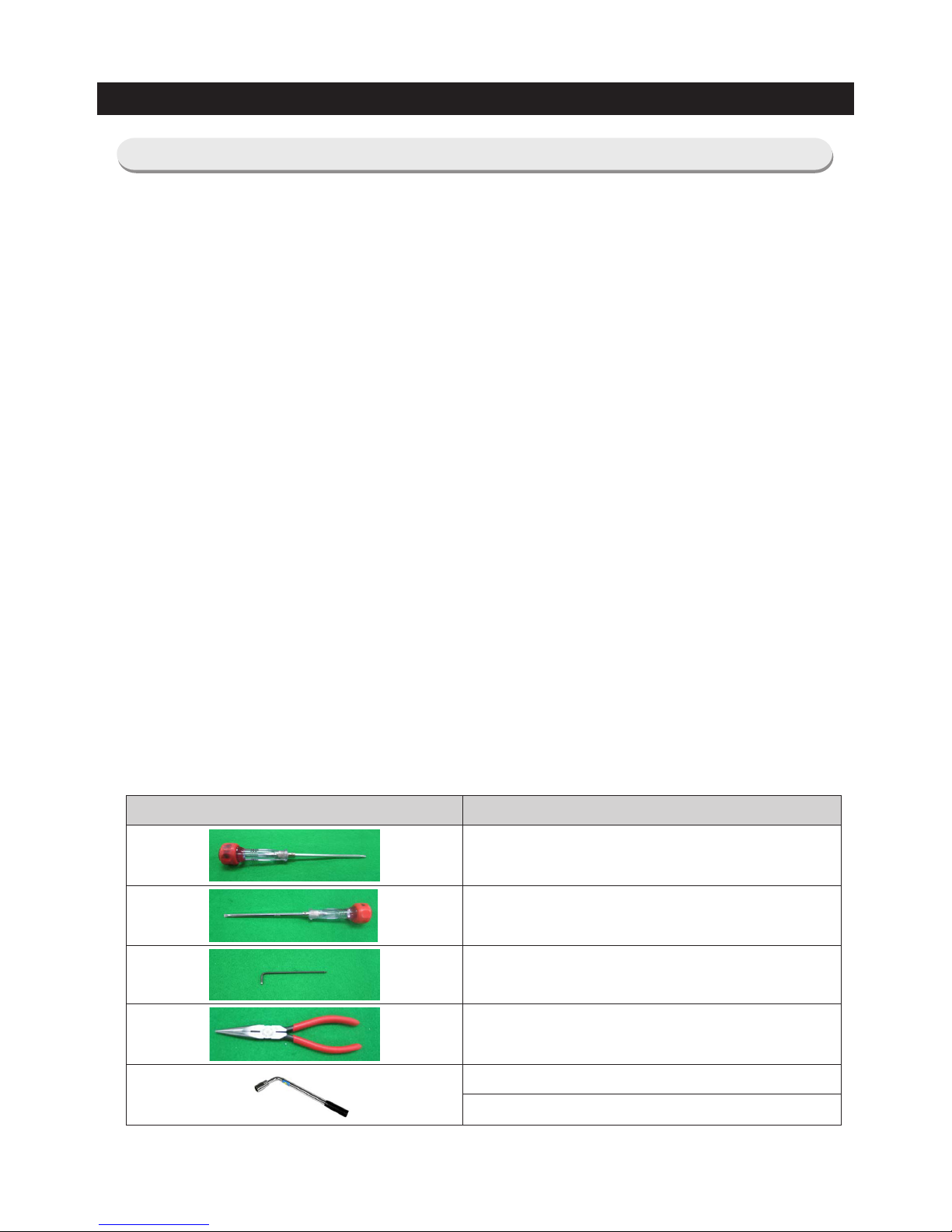
Required Tools
Image Item
(+) screw driver
(-) screw driver
Hexagon wrench (2 mm diameter)
Long nose pliers
Box wrench (12 mm) - To disassemble the compressor
Box wrench (10 mm) - To disassemble the hinge Lower
24
DISASSEMBLY AND REASSEMBLY
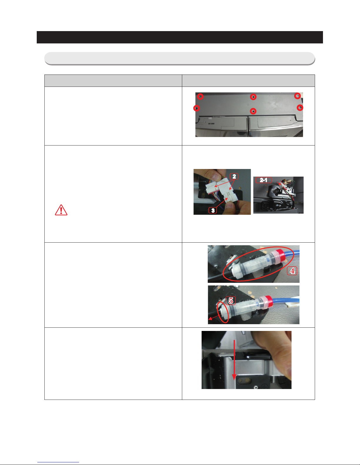
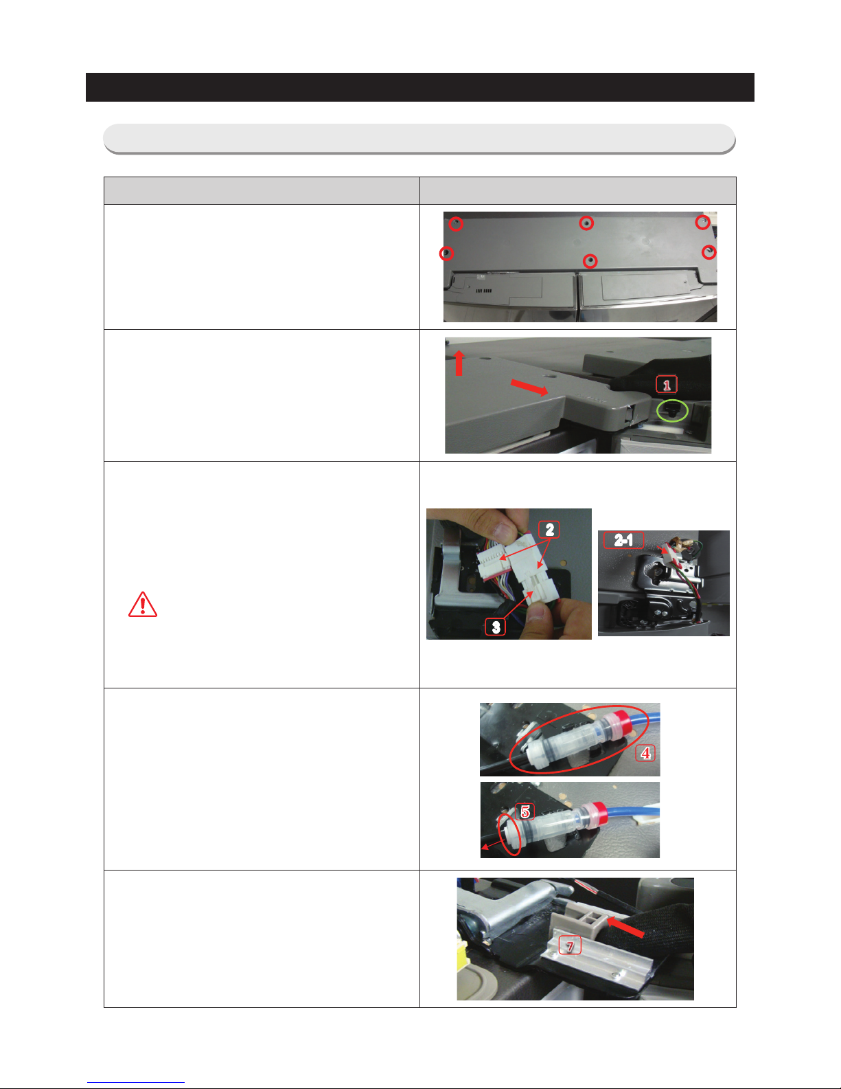
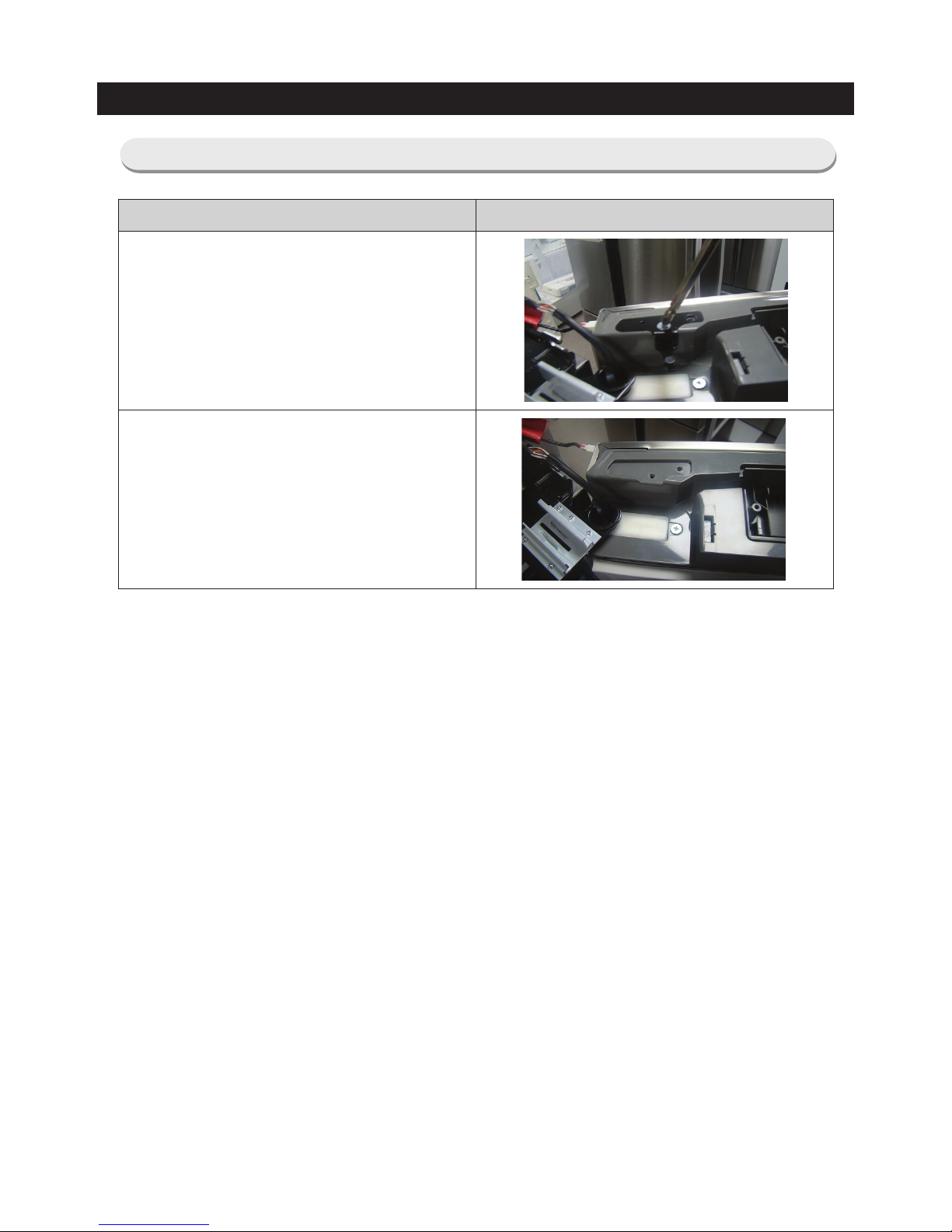
3-2. Disassembling the Refrigerator Door
How To Do Descriptive Picture
1. Remove the 6 screws fixing the Top Table and
separate the Top Table (①).
2. Separate the 2 housing connectors (②) from the
hinge at the top left of the fridge compartment
door and the 1 housing connector (②-1) from
the hinge at the top right of the door.
To separate the housing connectors more
easily, pull the connector while holding down
the fixing hook (③).
Caution
Make sure to unplug the power cord
before performing the procedures above.
Note. The number of housing units may differ
depending on the model.
3
2
2-1
3
2
2-1
3. As shown in the picture, Remove water tube
from hinge (4) by holding at the both sides of
the Tube Fitting and pulling it out. And, remove
the Tube Fitting (5) by pulling the water hose
after pushing in the locking ring tab at the end
of the Tube Fitting.
4. After pulling the Hinge Lever, remove the
Hinge.
25
DISASSEMBLY AND REASSEMBLY
How To Do Descriptive Picture
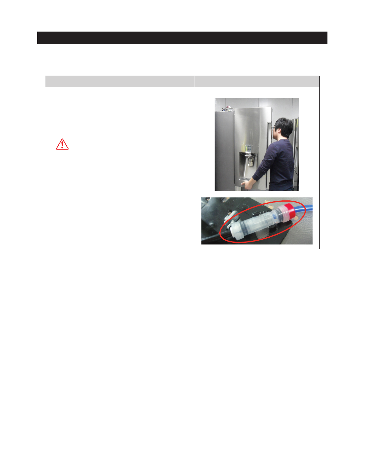
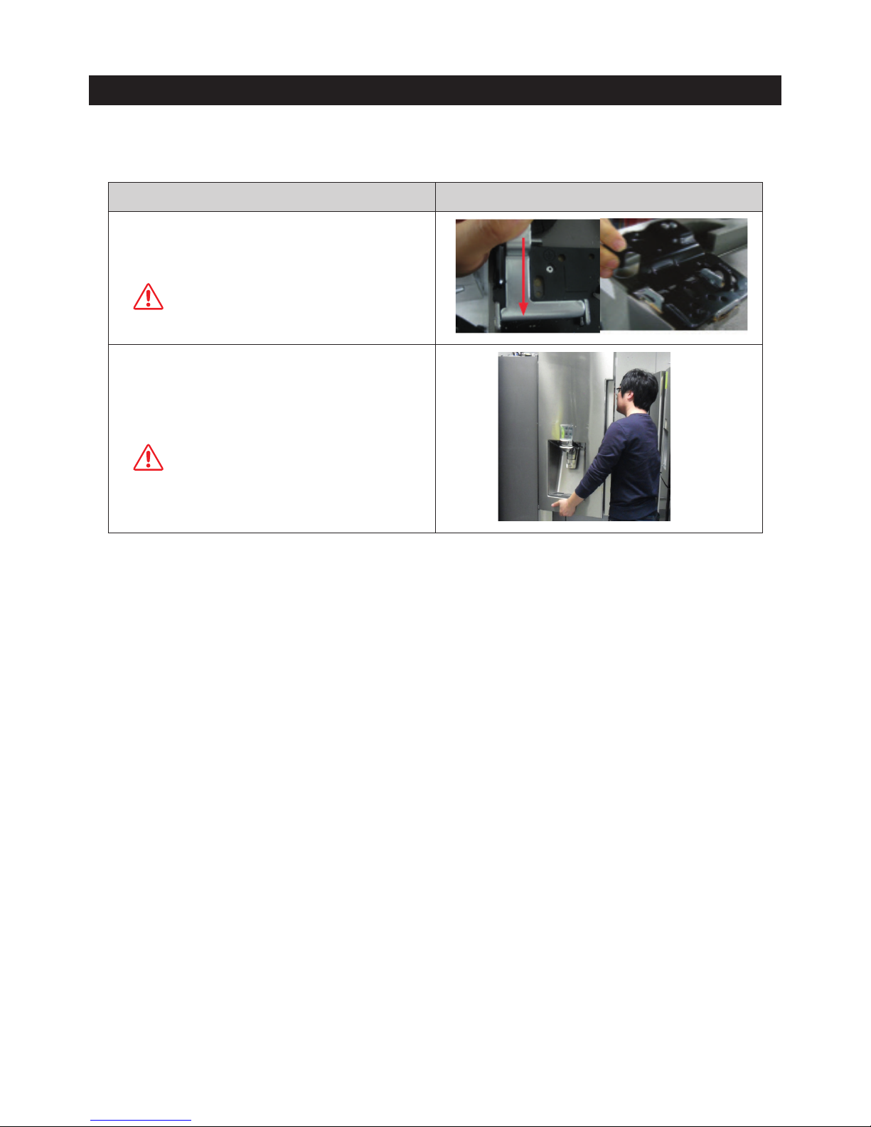
5. Lift the door straight up to remove while opening
it more than 90°.
CAUTION
Be careful not to drop the door.
6. Assemble the door in the reverse order of
disassembly; reconnect the fitting; connect the water
supply; check if water comes out from the dispenser;
and check if water leaks for one minute or longer. (You
can check the water with bare eyes at the transparent
fitting. If it is hard to observe with bare eyes, you can
also check it against a piece of toilet paper)
26
DISASSEMBLY AND REASSEMBLY
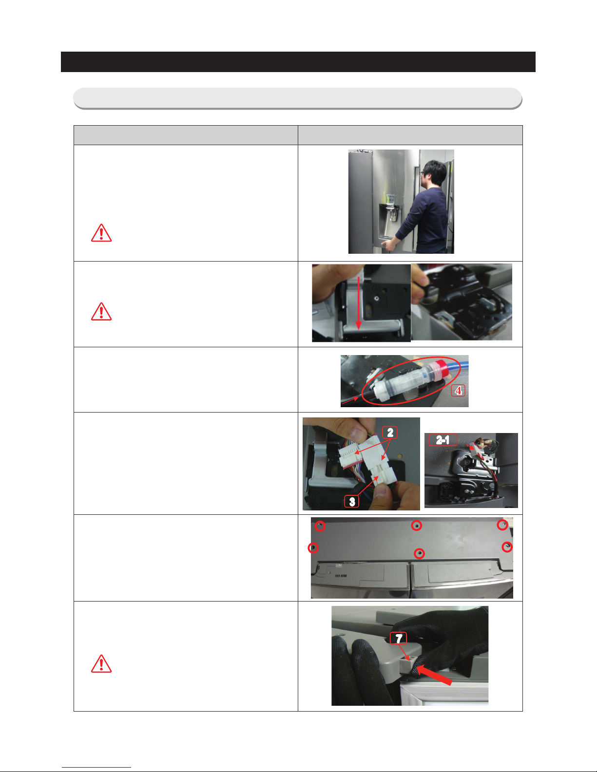
3-3. Disassembling the Fridge Doors (RF24J* only)
How To Do Descriptive Picture
1. Remove the 6 screws fixing the Top Table.
2. Open the right door of the fridge compartment
so that it does not interfere with the Bracket (②)
and the Top Table.
Lift the back side of the Top Table and pull it to
the front to disassemble.
3. Separate the 2 housing connectors (②) from the
hinge at the top left of the fridge compartment
door and the 1 housing connector (②-1) from
the hinge at the top right of the door.
To separate the housing connectors more easily,
pull the connector while holding down the fixing
hook (③).
Caution
Make sure to unplug the power cord
before performing the procedures
above.
[Note] The number of housing units may differ
depending on the model.
3
2
2-1
3
2
2-1
4. As shown in the picture, Remove the water
tube from hinge by holding at the both sides of
the Tube Fitting (④) and pulling it out. After that,
remove the Tube Fitting by pulling the water
hose after pushing in the locking ring (⑤).
[Note] For Dispenser model only
5. Push the Pusher (⑦) in the direction of the
arrow at the right hinge to disassemble.
27
DISASSEMBLY AND REASSEMBLY
How To Do Descriptive Picture
6. Pull the fixer from the hinge in the direction of
the arrow to separate, and then lift the hinge to
separate.
Caution
If the hinge is separated, the door may
fall down and hurt you, so hold the door
with both hands to disassemble.
7. Lift the door straight up to remove while opening
it by more than 90°. Disassemble the left door in
the order of 4 and 5.
Caution
Be careful not to drop the door.
28
DISASSEMBLY AND REASSEMBLY
3-4. Assembing the Fridge Doors (RF24J* only)
How To Do Descriptive Picture
1. Assemble the door to the middle hinge at the
position of 90 degrees.
(Fix the position for the shaft at the bottom of the
door to go into the groove of the middle hinge by
making the angle the same as the door's angle
during disassembly.)
Caution
Be careful not to drop the door.
2. After assembling the upper hinge, make sure to
fix it firmly by pressing the fixer.
Caution
While assembling the hinge, hold the
door with both hands to prevent the
door from falling down.
3. Completely insert the hose of the door part into
the Tube Fitting, and fix the Tube Fitting at the
hinge as in the picture.
4. Connect the 2 housing connectors (②) from the
hinge at the top left of the fridge compartment
door and the 1 housing connector (②-1) from
the hinge at the top right of the door.
[Note] The number of housing units may differ
depending on the model.
3
2
2-1
3
2
2-1
5. Assemble the Top Table (①), and lock the six
screws for fixing the Top Table.
6. Push the Pusher (⑦) in the direction of the
arrow to combine.
Caution
Completely insert the Pusher (⑦) for its
front side not to protrude.
7
7
29
DISASSEMBLY AND REASSEMBLY
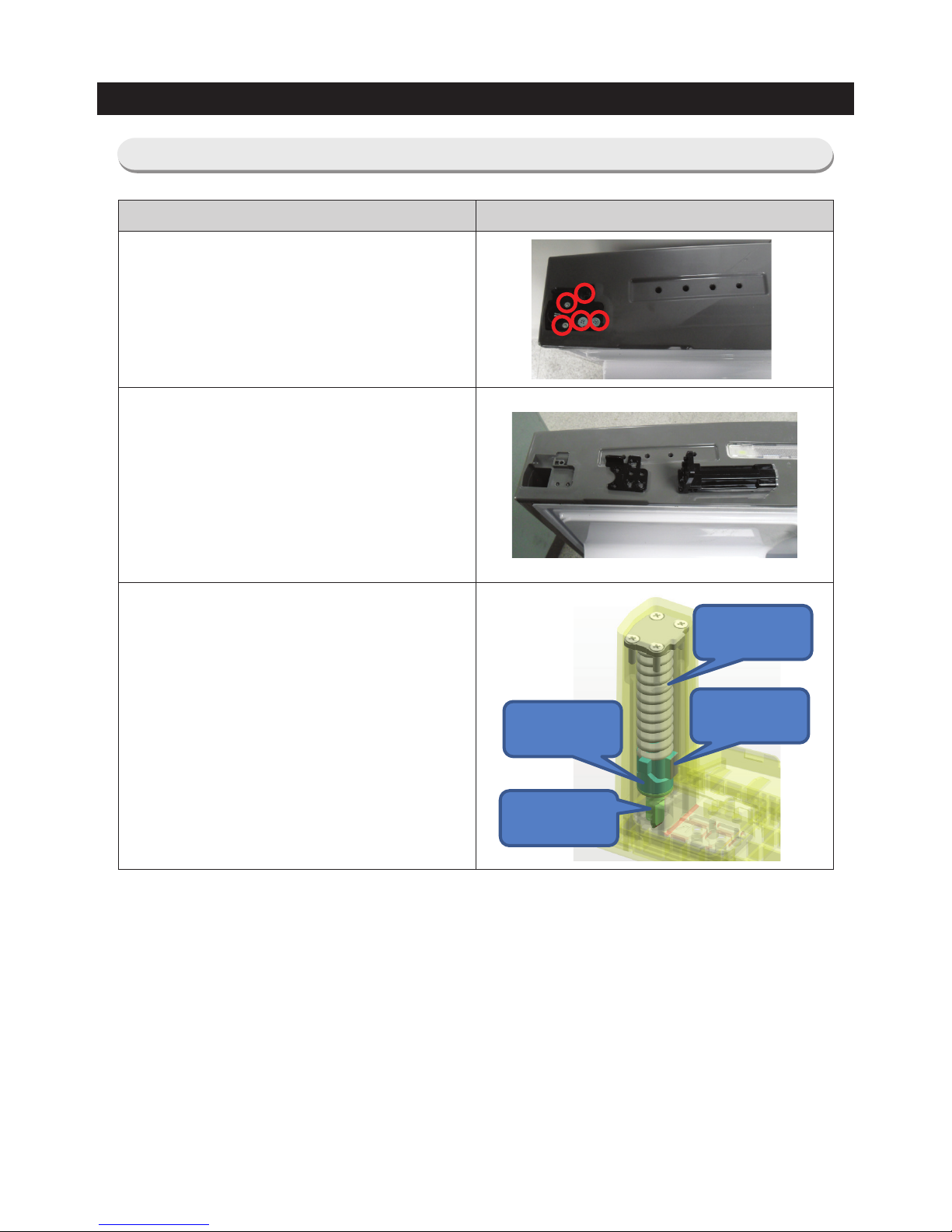
3-5. Assy Auto Hinge
How To Do Descriptive Picture
1. Remove the SCREW at 5 point under the
Refrigerator Door.
2. Lift up the stopper and auto hinge.
※ The working principle of the hinge.
Auto hinge make to work the door by torsion of
the spring.
Spring auto
close
Cam auto
close upper
Cam auto
close lower
Shaft auto
close lower
30
DISASSEMBLY AND REASSEMBLY
3-6. Braket (RF24J* only)
How To Do Descriptive Picture
1. Remove the Screw.
2. Remove the Bracket.
 Loading...